ARCH 473/3522 - DIGITAL DESIGN STUDIO AND WORKSHOP
Mehad Hanbal
Fall 2022
Student Portfolio
The American University in Cairo (AUC)
School of Sciences and Engineering - Department of Architecture
ARCH 473/3522 - Digital Design Studio and Workshop (Fall 2022
Student portfolio documenting samples of work submitted along the course, including research, experimentation, 3D modeling, digital fabrication, parametric design and modeling, physical model realisation and analysis.
Student name: Mehad Hanbal
Student ID: 900191879
© The American University in Cairo (AUC), September 2022
Mehad Hanbal Architecture Student
I’m a senior Architectural Engineering student at the American University in Cairo. I’m from Alexandria, Egypt yet I was born and raised in Doha, Qatar and moved to Egypt after my high school graduation. I have a hobby of drawing and painting, as I’ve painted a mural in the North Coast, Egypt that got viral during a certain period of time and another one in the indoor swimming pool of my high school, American School of Doha, Qatar. I painted decorative display boards for Starbucks in Doha Fesrtival City where my work was displayed. I customized Nike shoes for customers both in Egypt and Qatar through my startup business, Mehad Arts, that was initiated in Qatar. I was a student officer for a year and delegate for two years in the American School of Doha Model United Nations in which I formally re-
searched information under popular, global issues, practiced public speaking and negotiating around international students within the school. I also participated in two conferences in the Arabic Model United Nations in Qatar Academy where I would prepare speeches and discuss international issues in the Middle East and propose solutions in Arabic in a civilized, disciplined way. I was then a delegate for two years in the Hague International United Nations in Qatar in which I negotiated and debated over resolutions with other international students worldwide. As a General Manager of the Services committee in the Architecture Association for 2 years, I was able to create more than 250 student packs for the department as well as design and implement the co-working space at the AUC’s Architecture department. I also worked as a student teaching assistant for Digital Representation Tools for Architects (ARCH 273/1521) in which I helped students how to use Revit, Rhino, and Photoshop and was committed to attending 2.5 hours, twice a week, as well as offering extra help on Zoom. I also recently learned adults beginners ballet and took a Shoe Design course where I was committed to attending it 2.5 hours twice a week during the semester in which I learned how to design and create a shoe from scratch and work with local workers in the industry. I’ve also did a summer abroad in John Cabot University in NGO Consulting and I’m currently a research assistant.

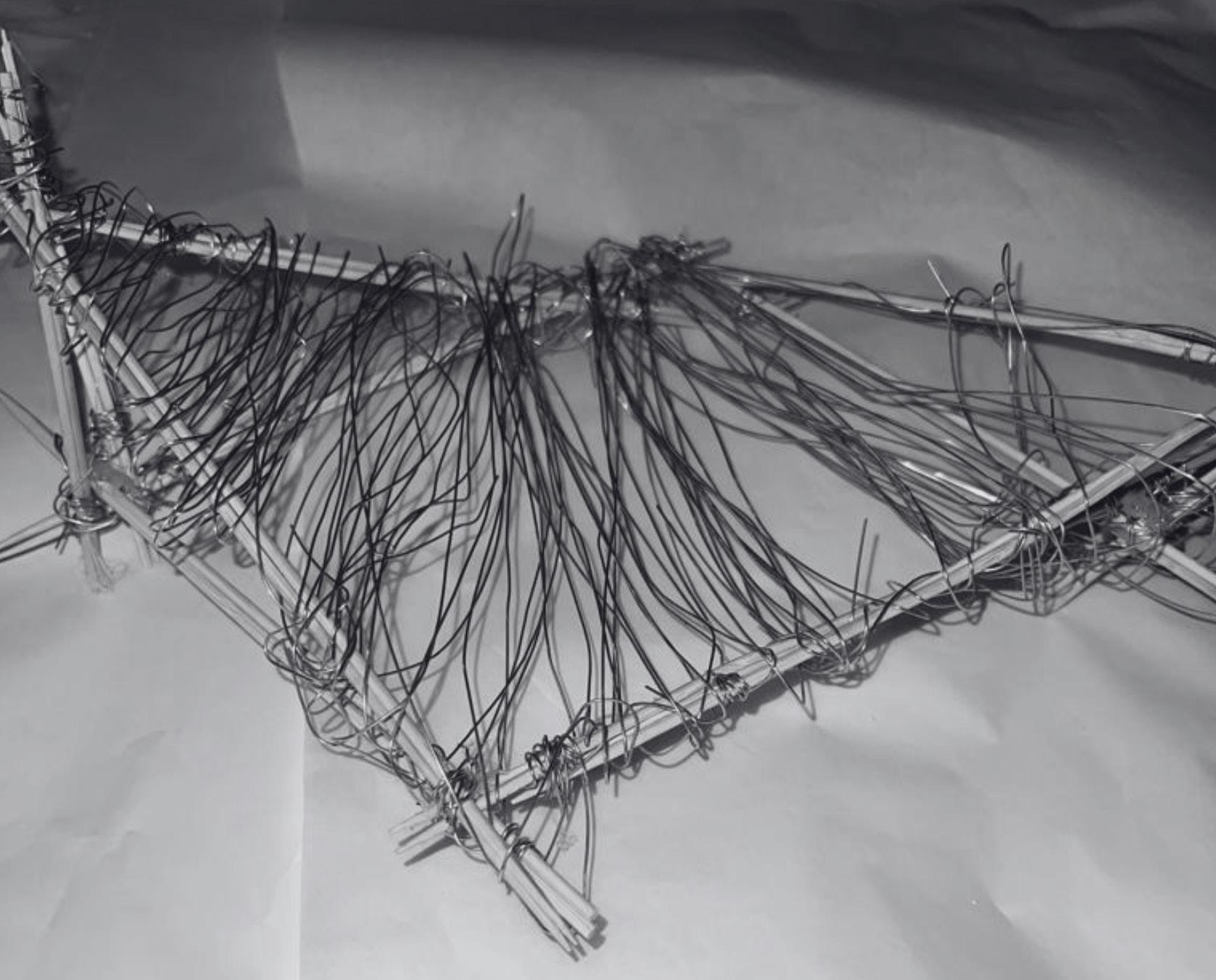
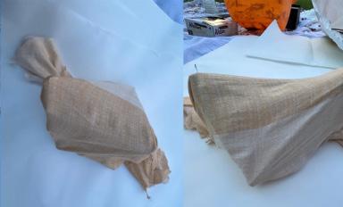
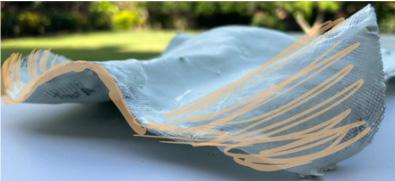
First try in experimenting with fabric formwork by creating a cable net, timber frame, & fabric, inspired by a precedent
Project 1: Learning from Materiality
01
https://www.semanticscholar.org/paper/Design-process-for-prototype-concrete-shells-using-Veenendaal-Block/9ecb734bd541397e124e05208ca6ce84d783954a#paper-header
Stage 1 Material Exploration
Trial 1
History and Background
Fabric Formwork uses structural membranes as the main facing material for concrete molds, resulting in a highly flexible that can deflect or change its curvature shape under pressure.
In Roman times, the fabric was a result of the Industrial Revolution; when building cofferdams, retaining walls would be built by having them filled with clay in woven reed baskets, allowing for easy removal of the falsework after the concrete hardens. Fabric formwork reduces construction time and costs, the permeability of fabric reduces the number of air voids improving the overall durability.
Specific Fabrication Approach: Fabric Formwork
Precedents
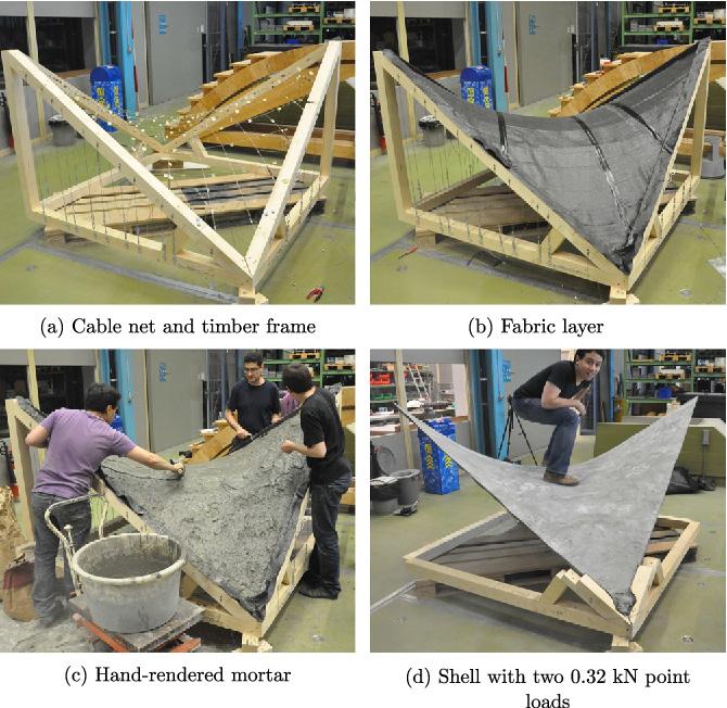
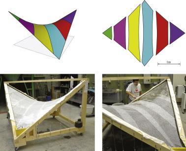
For the first trial in the Material Exploration stage, I was inspired by the following examplesin Fig. 1, 2., and 3., that explain the design process for prototype concrete shells using a hyprid cable-net and fabric formwork (D. Veenendaal). The precedents demonstrate the creation of thin concrete panels: substructure of flexible wire mesh & a lining made of latex sheet which is what determined the panel’s final form.
https://www.holcimfoundation.org/projects/latex-formwork
Chapter name Portfolio 2 Learning from Materiality
Fig. 2 Latex Formwork
Fig. 1 Design process for prototype concrete shells using a hybrid cable-net and fabric formwork
https://www.semanticscholar.org/paper/Design-process-for-prototype-concrete-shells-using-Veenendaal-Block/9ecb734bd541397e124e05208ca6ce84d783954a#paper-header
Materials Used: Gypsum, Water, Bedsheet, Plastic Wrap, Wire, Nasebian, Tape, Cardboard Box, Glue Gun, Cardboard
Creating thin concrete panels: substructure of flexible wire mesh & a lining made of latex sheet determining panel’s final form.
Main Domain of Application: Plastic Roll
Second Domain of Application: Nasebian (for borders of formwork)
Process:
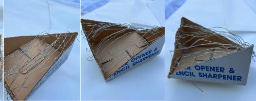
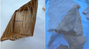
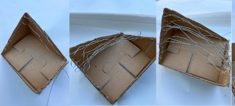
1) Cut Cardboard Box Into Triangular Pieces for Creating “Frames”
Process
Student Name ARCH 473/3522 - Spring 2019 3 ARCH 473/3522 - Fall 2022
Learning from Materiality
2) Insert Wire as “Cable Network” & Create Openings for Wire Insertion
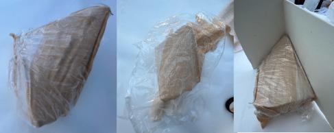
4) Add Domain of Application (Plastic Wrap for Separate Gypsum) & Nasebian to Prevent Gypsum from Sagging at Edges
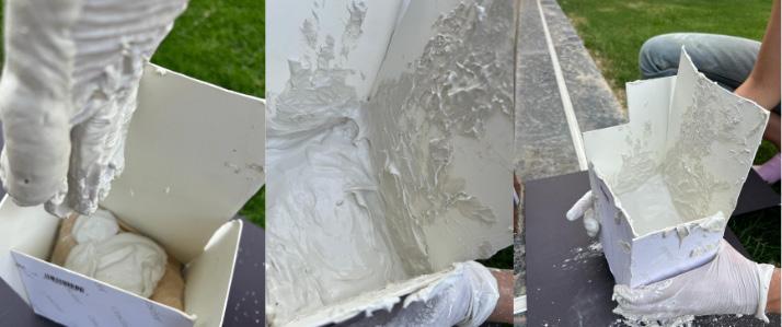
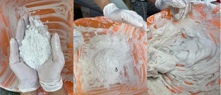
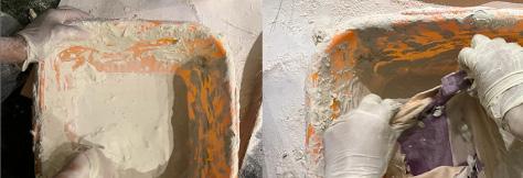
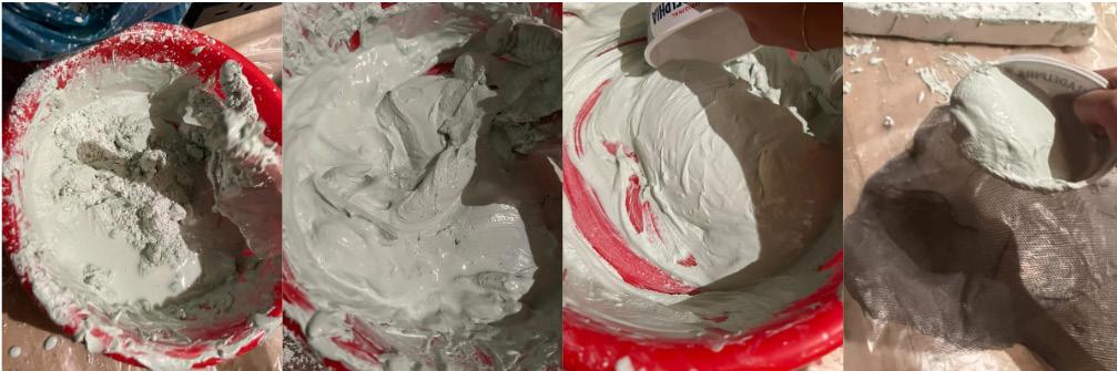
5) Mix Gypsum With Water
Ratio 1:2

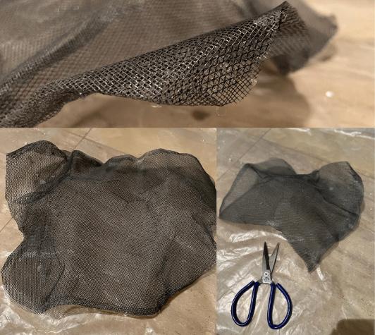
3) Add Fabric Layer (Bedsheet Piece)
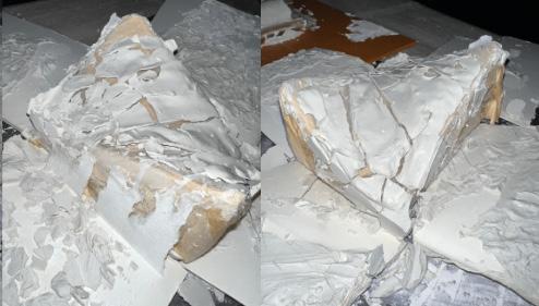
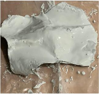
6) Pour Gypsum on Formwork
Learning from Materiality Portfolio
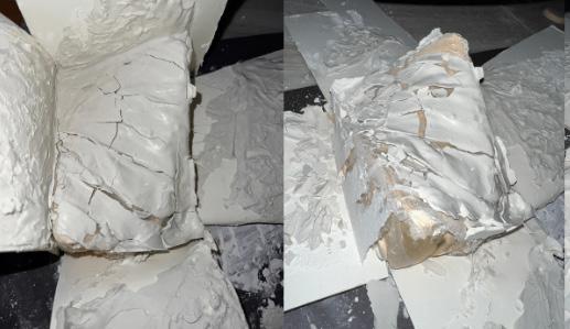
Result and Reflection:

There was a lot of cracks and although the nasebian idea did help have a smooth edge, it still wasn’t effective due to such cracks.
Fall 2022 ARCH 473/3522 - Fall 2022
Process
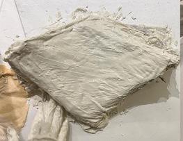
1) Cut Tissue Rolls Into Halves as Casting
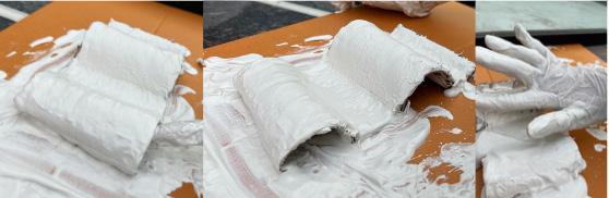
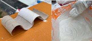
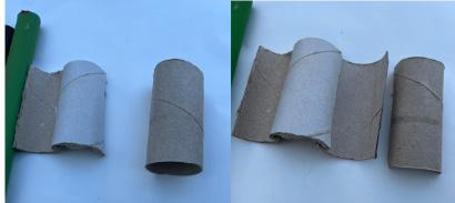
Formwork
Stage 1 Material Exploration
Trial 2
Materials Used: Tissue Rolls, Glue Gun
2) Glue Them Together
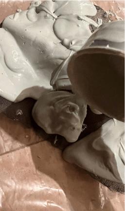
3) Pour Gypsum with Water Ratio 1:2

Learning from Materiality
Portfolio
Materials Used
New Technique
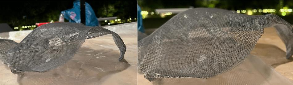
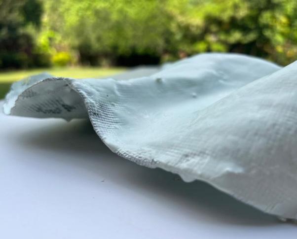
Result and Reflection:

Creating thin concrete panels: substructure of flexible wire mesh & a lining made of latex sheet determining panel’s final form.
I missed the step of adding the plastic layer as a separator for gypsum. Gypsum & water connected well with this cast. Add plastic layer next time for removal to see actual effectiveness.
https://www.sciencedirect.com/science/article/abs/pii/S0141029614003344
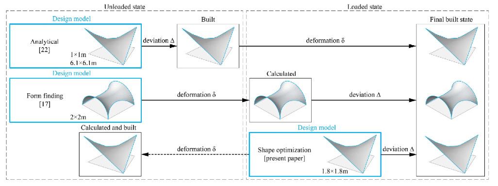
Fig. 4 Design process for prototype concrete shells using a hybrid cable-net and fabric formwork
Stage 1 Material Exploration
Trial 3
Specific Fabrication Approach: Fabric Formwork
As shown in Fig. 4, I was still inspired by the same precedent from Fig. 1 and thus I’ve used the same objective of achieving the same result.
Precedent
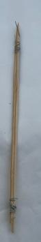
2) Join Sticks Together in Triangular Form with Glue Gun
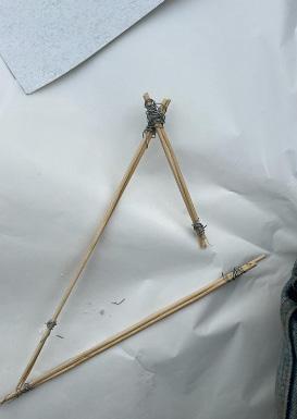
Process
1) Wrap Wooden Sticks With Wire
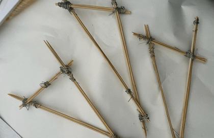
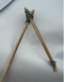
3) Wrap Wires as “Cable Network” as Before
Chapter name Portfolio 8
Learning from Materiality Portfolio
Materials Used
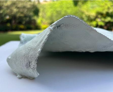
Result and Reflection:
The support from the wire and the wooden sticks were a better improvement than the initial fabric formwork.
Overall Reflection:
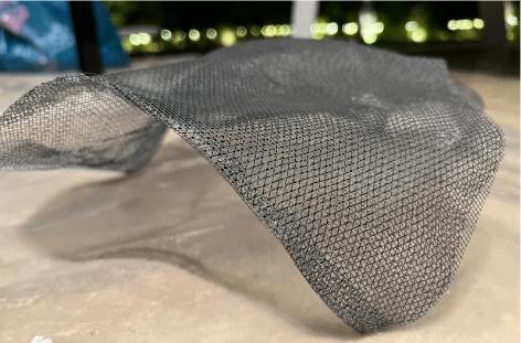
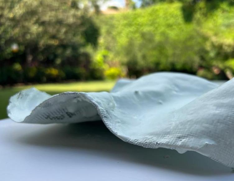
I did three trials in this stage, experimenting with a strong objective at the start of creating a cable network before pouring the gypsum & water as a support, then diverting into a casting technique with no rigid idea in mind, and finally reverting back to fabric formwork techniques with soaking fabrics instead to create my final form.
Student Name
Spring
9
ARCH 473/3522 -
2019
4) Soak Bedsheet Piece (Fabric) in Gypsum with Water
Fall
Fall 2022 ARCH 473/3522 -
2022
One of the last trials in experimentation with fabric formwork using gypsum, water, and the cable net technique
Project 1.2: Material Exploration
02
Precedents
Stage 2 Material Experimentation
Trial 1
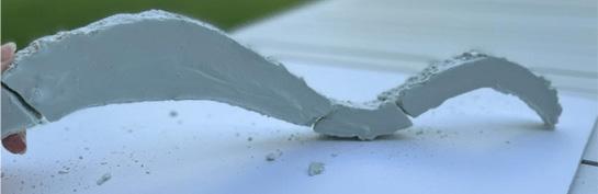
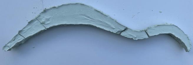
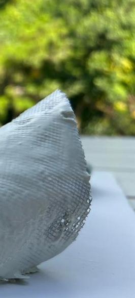
Specific Fabrication Approach: Casting
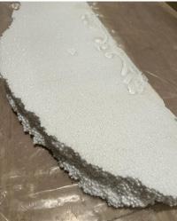
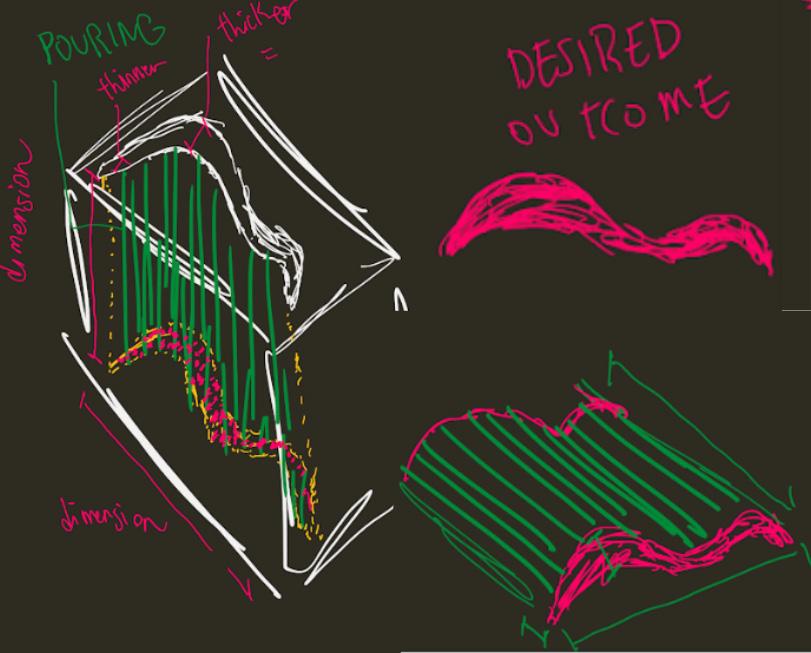
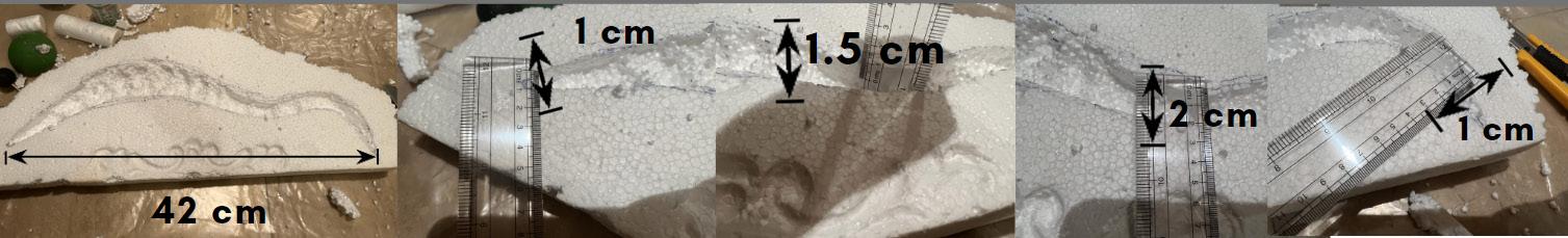
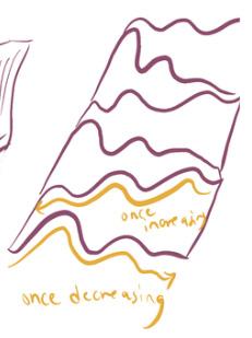
(aimed to have this part thicker) (aimed to have this part become gradually more thinner)
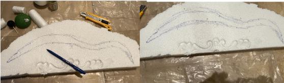
Initial Thought Process Through Sketches
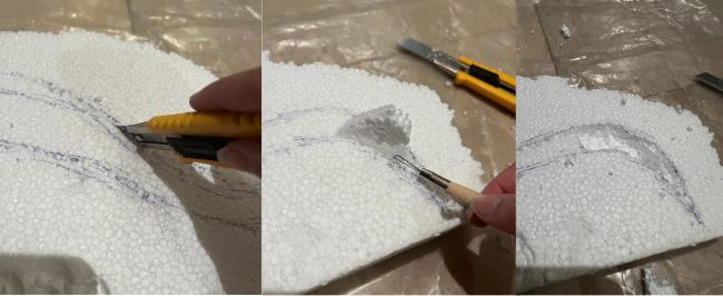
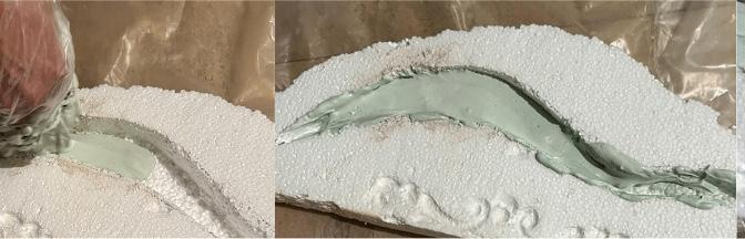
1) Draw Shell Design on Foam
Materials Used: Foam
2) Use Cutter to Cut Shape of Shell & Pull Out Foam
Learning from Materiality Material Exploration
Chapter name Portfolio 12
Student Name ARCH 473/3522 - Spring 2019 13
Fall 2022 ARCH 473/3522 - Fall 2022
Foam
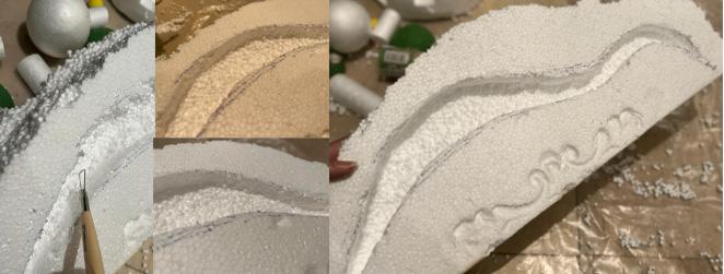
4) Smoothen Edges
3) Take Dimensions
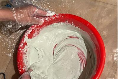
5) Begin Mixing Gypsum w/Water Ratio 1:2
(Very Weak Method of Pouring)

7) Even/Spread Out/ Distribute Remaining Gypsum Along Surface for Flat Surface
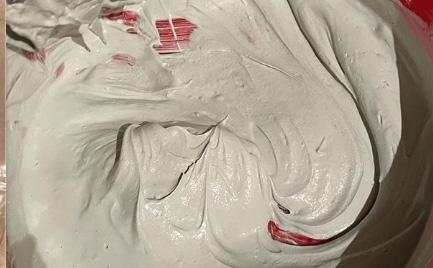
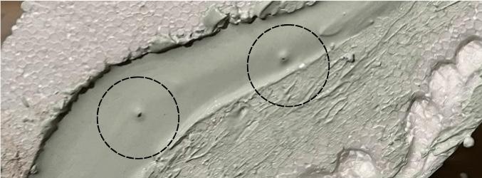
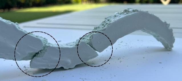
Precedents Possible Justification As To Why Cracks Were Caused Here Since Pouring Wasn’t As Smooth In This Area
6) Start Pouring
Chapter name Portfolio 14 Material Exploration
Some Appearance of Air Voids
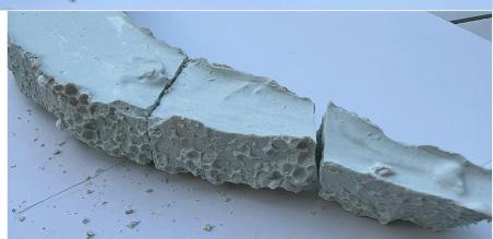
Interesting Texture of Foam Bubble Pattern
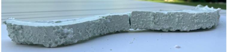
Result and Reflection:
Technique
The cracks were as expected due to the predicted air voids caused by the interference when pouring (evident at relatively thinner areas). I could’ve added slightly more gypsym for better hold and increased the depth to compensate for the thin areas to give more strength and hold.
Student Name ARCH 473/3522 - Spring 2019 15
Fall 2022 ARCH 473/3522 - Fall 2022
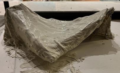
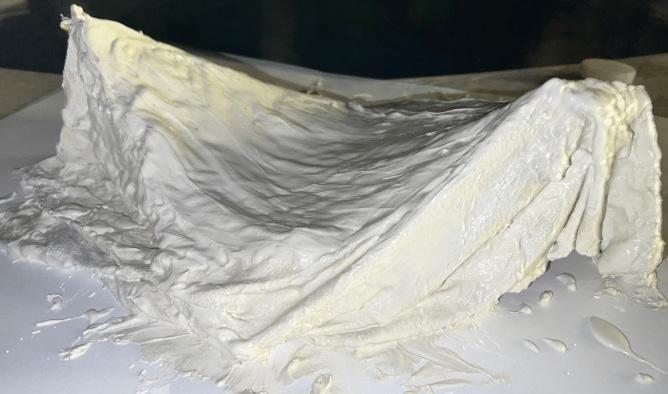
Materials Used: Light Silk on Heavy Silk Process
1) Cut into Desired Shape
Stage 2 Material Experimentation
Trial 2
Specific Fabrication Approach: Cable Net
Materials Used: Light Silk on Heavy Silk
2) Make More Bendings to Shape As Desired for Different Heights / Boundaries / Restrictions
3) Mix Gypsum With Water (Increase Gypsum Due to Large Surface Area & To Allow Paste to Take Proper Shape)
Material Exploration Learning from Materiality
Material Exploration
Chapter name Portfolio 16
Materials Used
4) A mess occurred as I didn’t know how to evenly distribute the paste without having to interfere myself as distribute it among the formwork manually.
...So I had to interfere and even out the paste with my hands, then shake the formwork slightly to balance it out (risking high chance of creating air voids and possible cracks).
I made sure the points (coordinates) touching the ground were strong enough to stay standing so it takes the proper concave shape.
Student Name ARCH 473/3522 - Spring 2019 17 Fall 2022 Fall 2022 ARCH 473/3522 - Fall 2022
MaterialMaterialExplorationExplorationLearning from Materiality
Portfolio
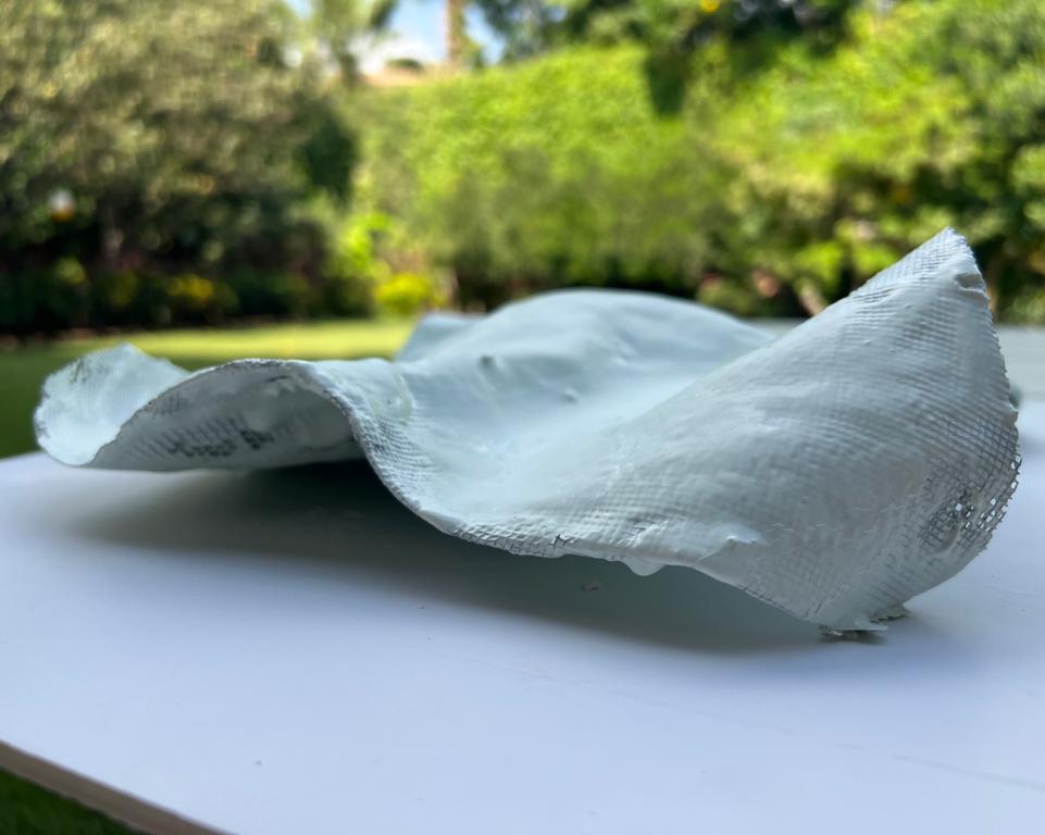
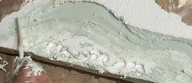
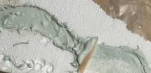
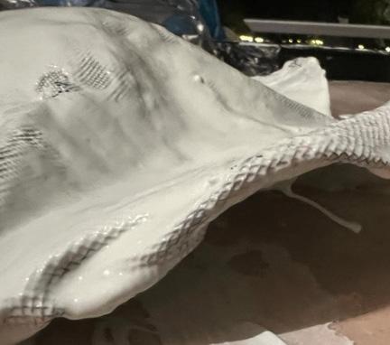
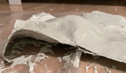
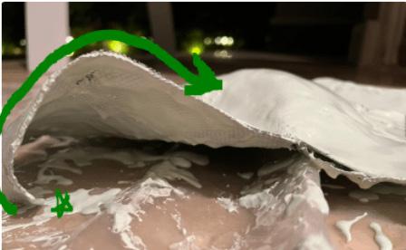
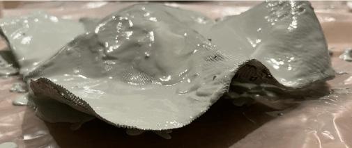
Result and Reflection:
I was Impressed by the result as the paste took shape of the silk quite well, yet I was questioning how pouring could’ve been improved to avoid some clumpiness.
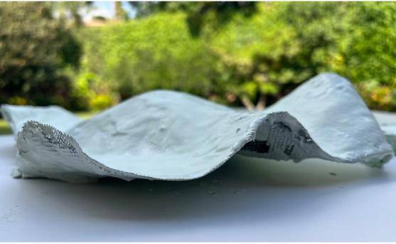
Even this point stayed in same position as silk was strong enough (had proper support) to dry as such.
19 Fall 2022 Fall 2022 ARCH 473/3522 - Fall 2022
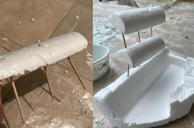
Random Exploration of Materials’ Relationships
Stage 2 Material Experimentation
Trial 3
Specific Fabrication Approach: Casting Materials Used: Foam & Wooden Sticks
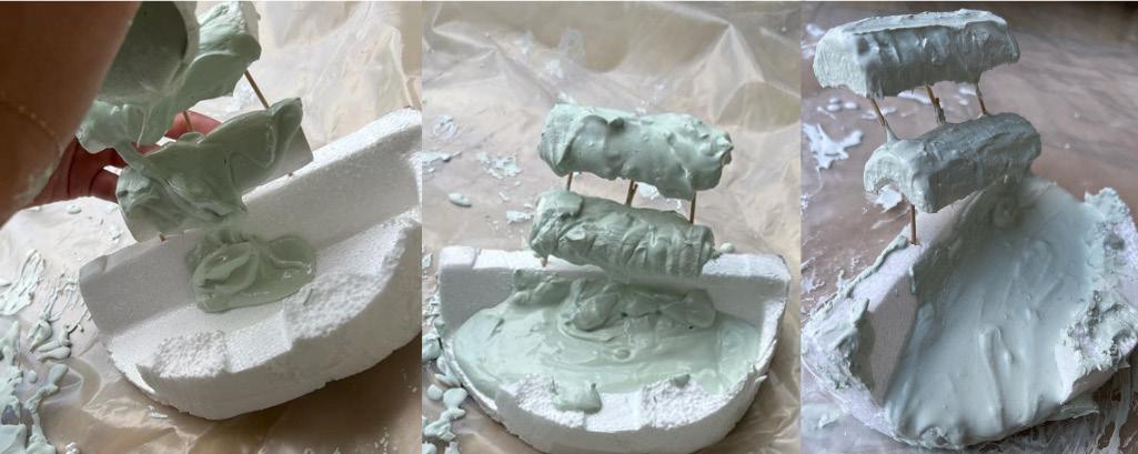
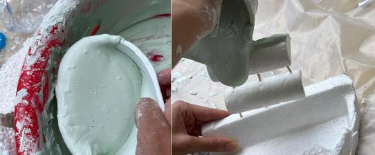
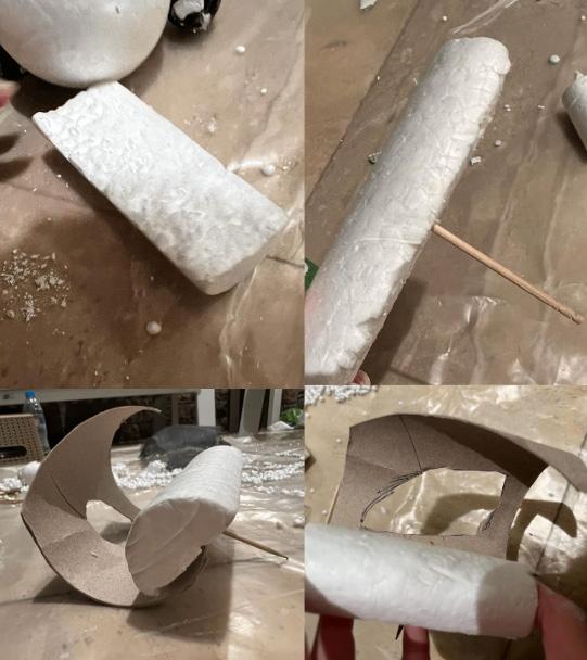
Change of Direction in Thought Process
Creating a “Cascade” Effect
Material Exploration
Material Exploration
Portfolio
20
Materials Used No Boundary
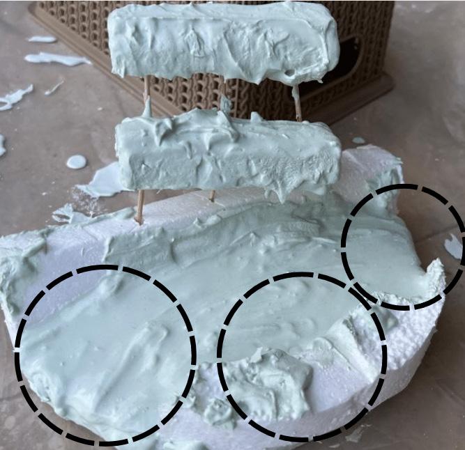
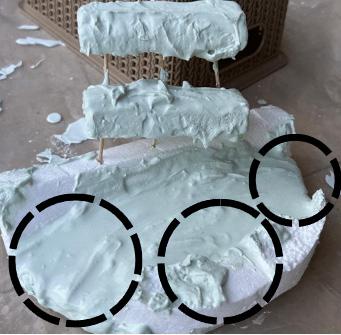
I didn’t think enough of what I’ll do with the toothpicks I’ve put, after the paste would dry. I was trying to experiment something different, with boundaries at some areas, and others not to see the effect of putting restrictions. I wanted to create a somewhat dripping effect to capture “water effect in motion” like a waterfall/cascade.
Boundary No Boundary
Result and Reflection:
It took good shape after formwork was removed, there were no connections between the cast so it was a very weak idea.
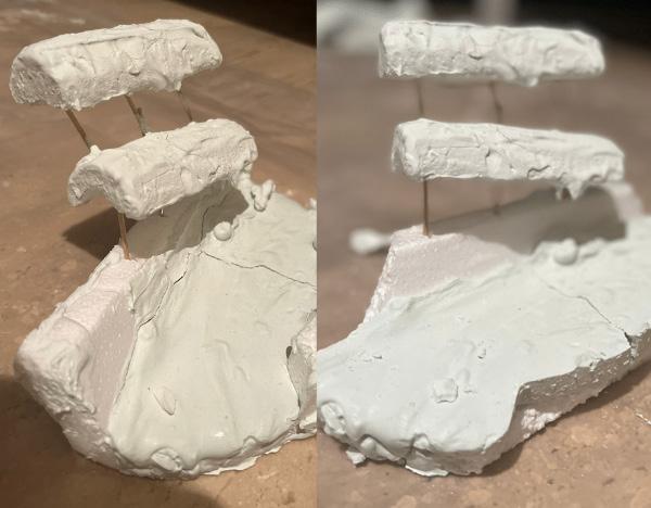
Overall Reflection:
I continued developing by uing the casting technique in trial 1, resulting in cracking due to interference with my hands when pouring. I then used a different technique using silk inspired by the previous cable net precedent, which resulted in the most smooth outcome. Lastly, the last trial was experimenting something without much thought or objective as I wanted to get slightly out of the box, resullting in a good shape with the proper restraints I created below, and formwork was successfully removed, yet there was no connections between the three small forms.
Fall 2022 Fall 2022 ARCH 473/3522 - Fall 2022
21
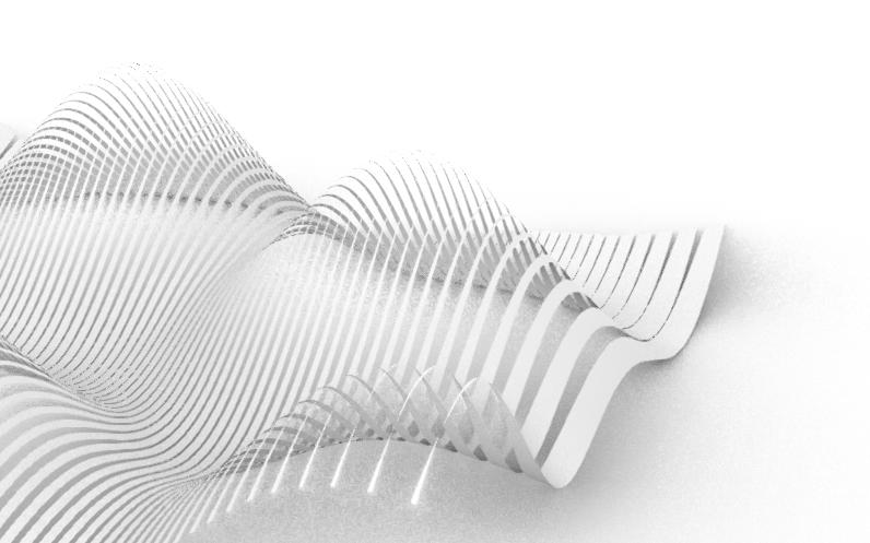
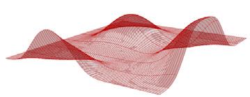
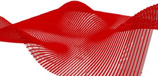
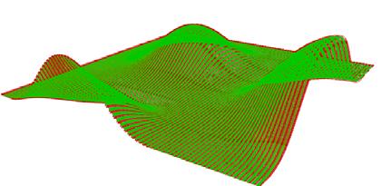
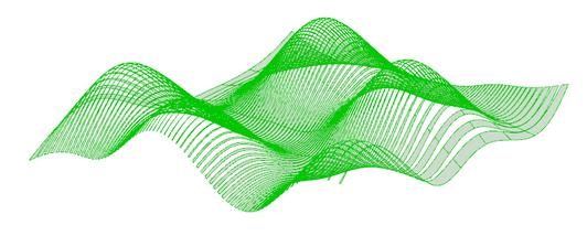
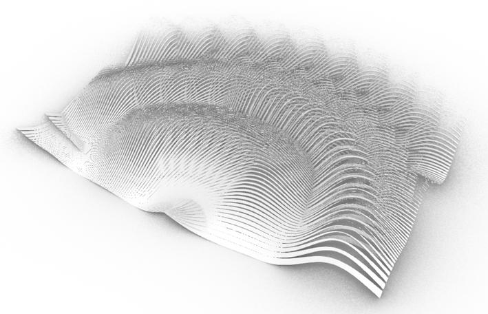
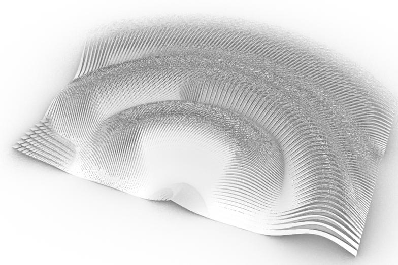
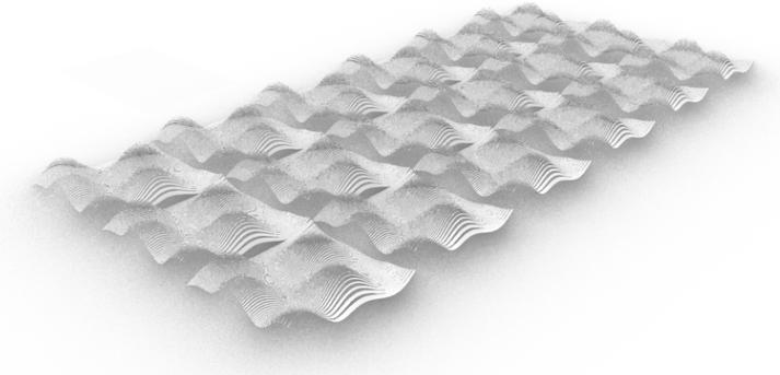
Forming a Single Panel Design Using Different Alterations of Parameters
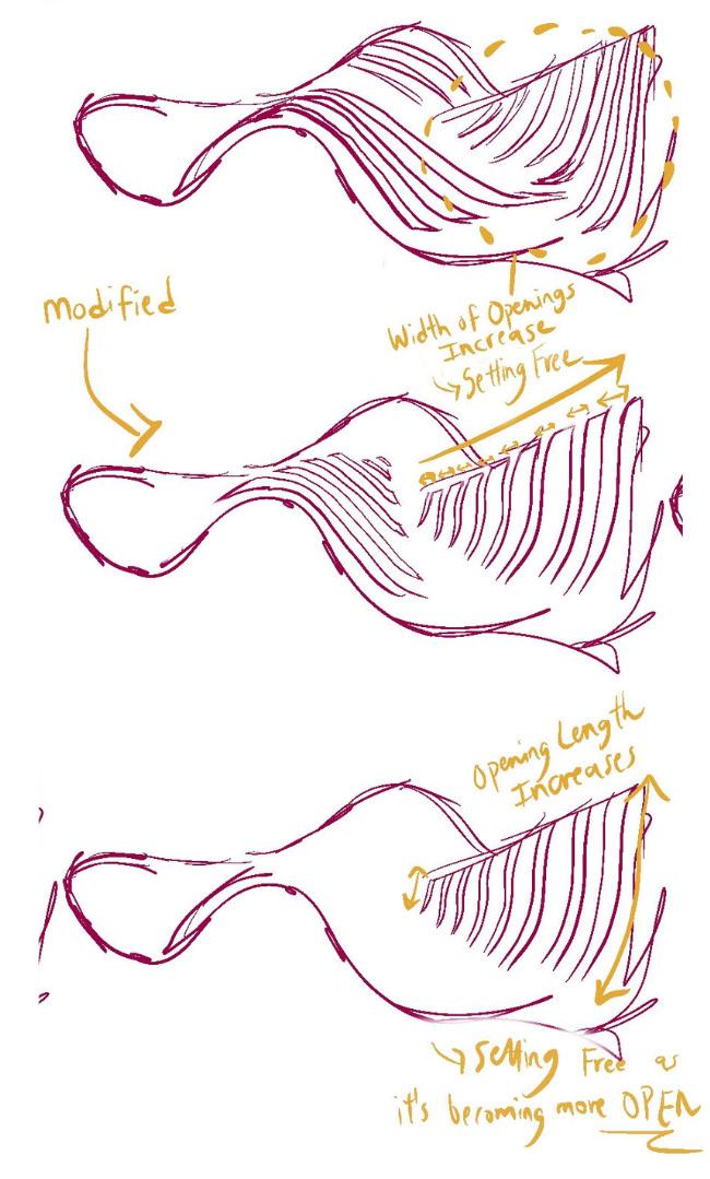
Project 1.3: Parameters Deduced & Workflow Diagram
03
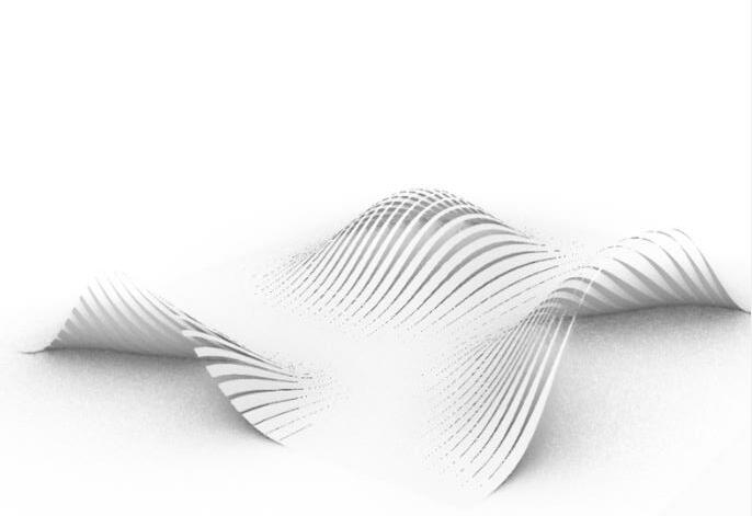
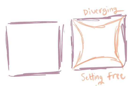
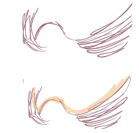
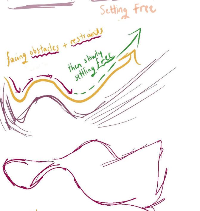
Setting Free
Chapter name Portfolio 24
Student Name ARCH 473/3522 - Spring 2019 25
Stage 3 Parameters Deduced & Workflow Diagram
Material Exploration & Concept
Chapter name Portfolio 26
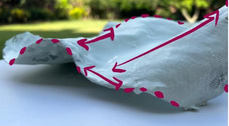
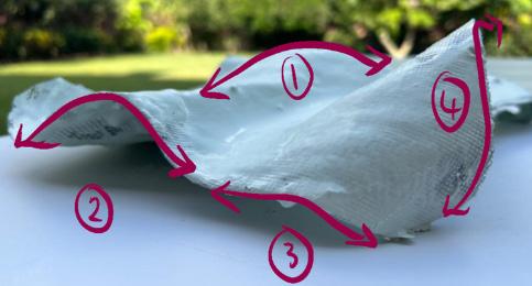
Sketch of Concept on Selected Panel
Parameters
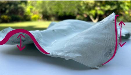
Height of Curves
Distance Between Each Curve
Number of Concave Curves
Curve Wavelength
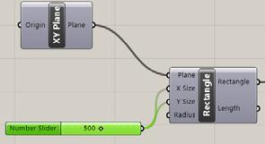
Width & Length of Surface Surface Thickness
Student Name ARCH 473/3522 - Spring 2019 27
Workflow Diagram
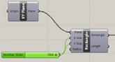
Larger Rectangle Size (X & Y)


--> Narrower Curves Become
Larger U/V Count (Greater Points in X and Y Direction)
--> More Oscillations Curves)
--> Greater Height of
--> Shorter Wavelength
Chapter name Portfolio 28 C ea e a P ane Chang ng Numbe o Po nt Ve ca y & Ho zon a y O u t p u t s Spec ed Po n Spec f ed W dth Spec ed Length C eate a P ane Chang ng Numbe o Po n Ver ca y & Ho zonta y O u t p u t s Spec ed Po n Spec ed W dth Spec ed eng h
Specified Width Specified Length Specified Point Specified Width Specified Length Create a Plane Changing Number of Points Vertically & Horizontal
Parameter Alteration: Width
Surface Parameters Alteration: Curve Wavelength
& Length of
(Greater Number of Direction)
(Number of Curves Wavelength


Parameters Alteration: Height of Curves
Parameters Alteration: Distance Between Each Curve
Parameters Alteration: Number of Concave Curves (with void)
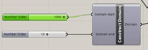
Greater Domain End (Constant Domain Start)

---> Less Wavelength (More Narrow)
Greater Domain Start (Constant Domain End)
--> Decrease in Curve Height
Student Name ARCH 473/3522 - Spring 2019 29 Numbe o Po n s n X D ec on Numbe o Po n s n X D ec on Nu
Number of Points in X Direction Number of Points in Y Direction Domain Start (Minimum) Domain End (Maximum)
Curves by Altering
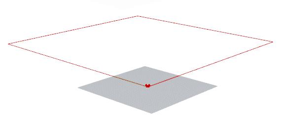
Construct Domain
Divide Surfaces into Points Create
Points
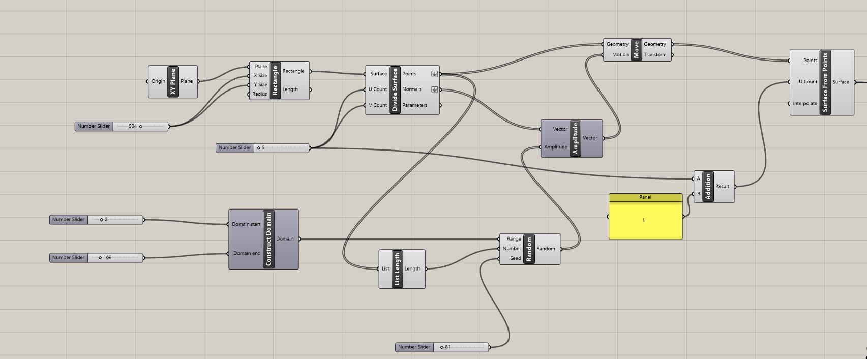
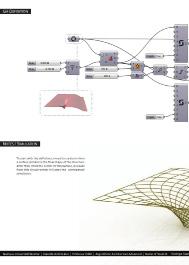
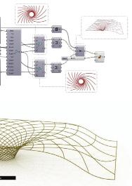
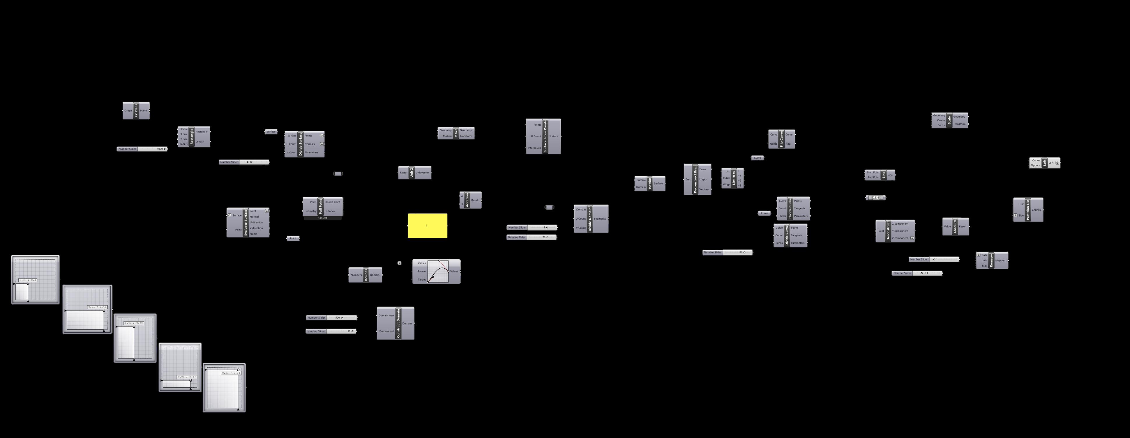
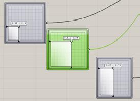
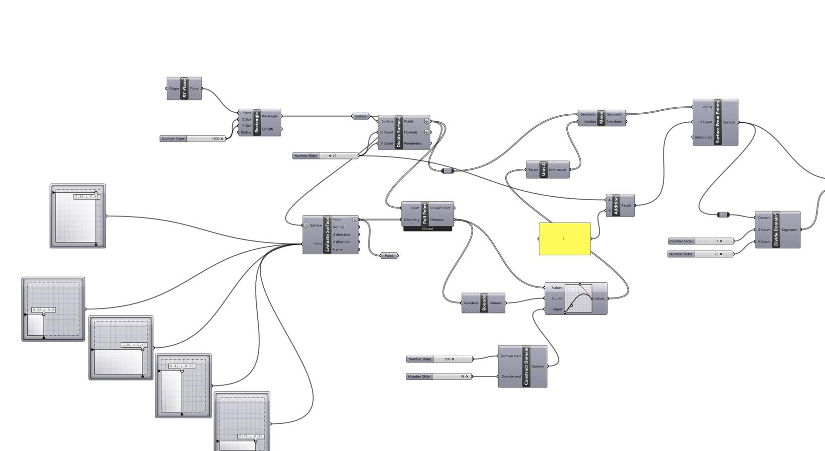
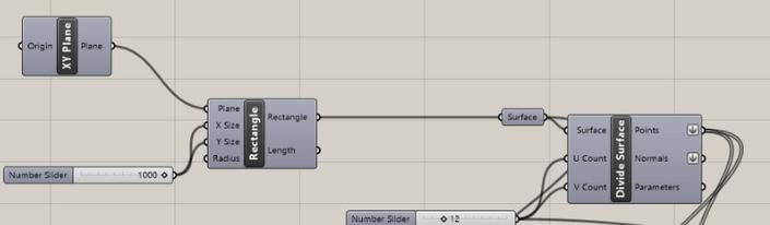
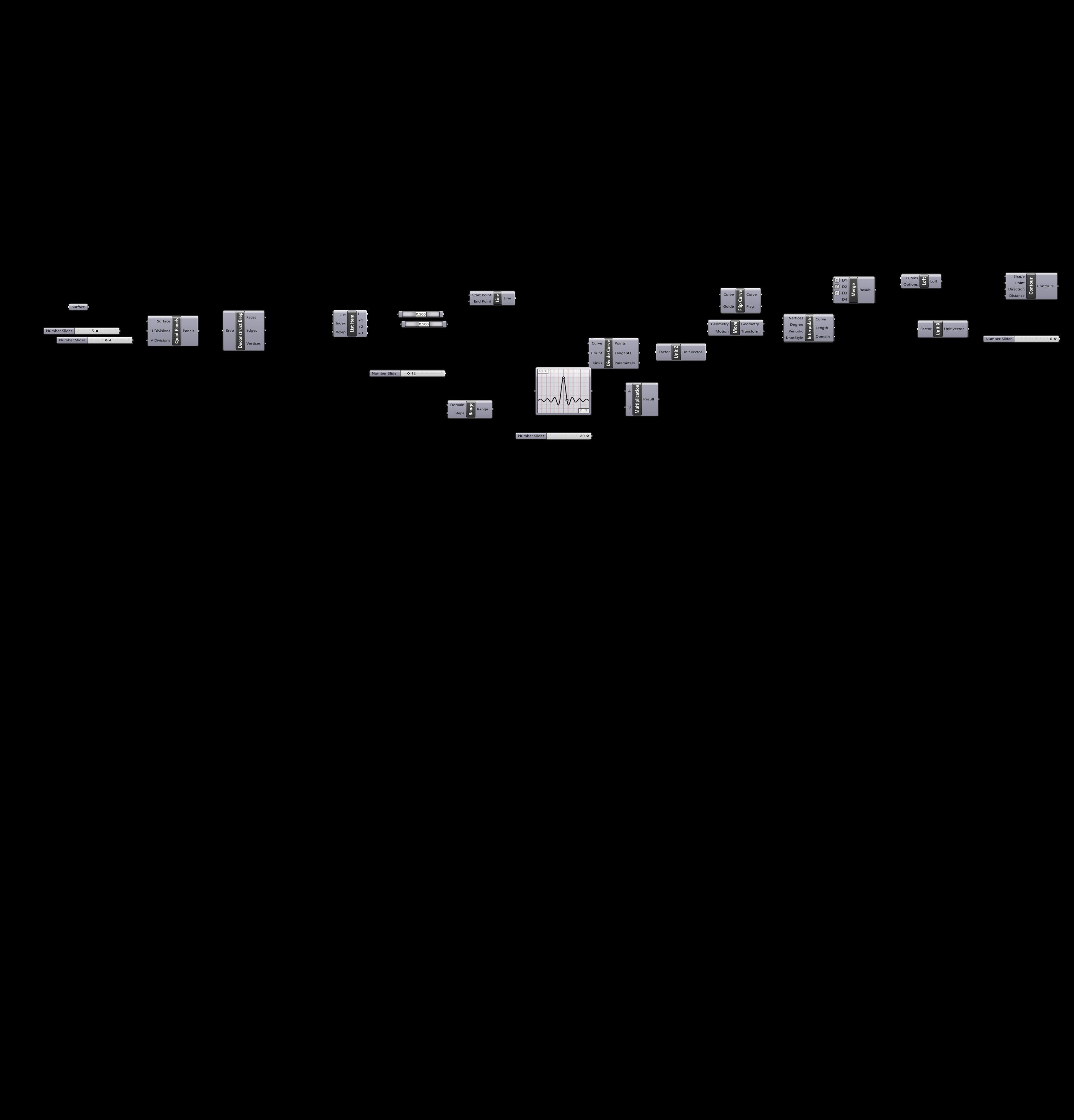
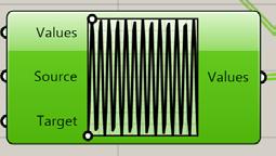
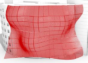
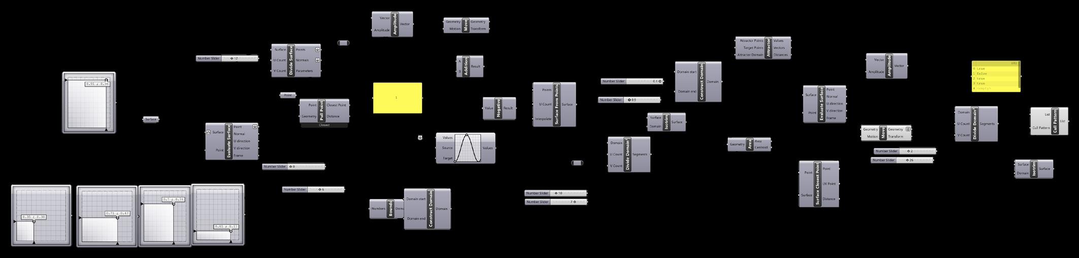
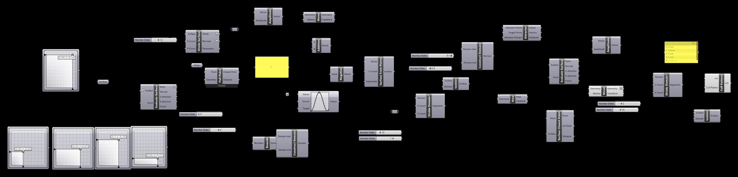
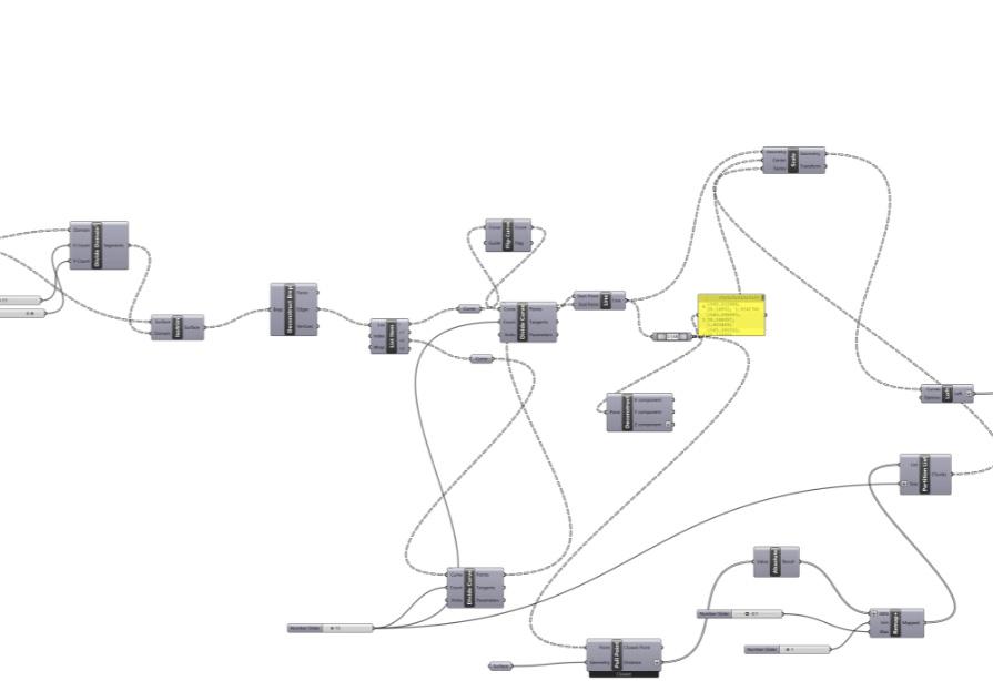
Translation of Workflow into Grasshopper

Parameters:
Surface Width & Length
Curve Wavelength
Curve Height
Number of Curves
Distance Between Curves
Thickness of Surface
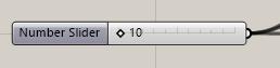
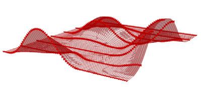
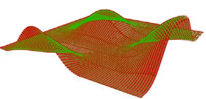
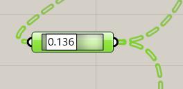
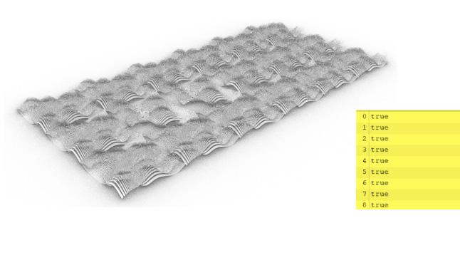
Initial Draft with Random Command (Random Points
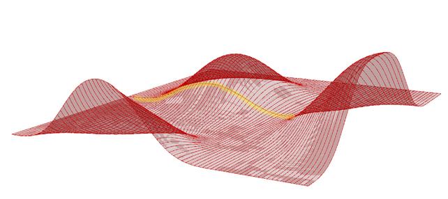
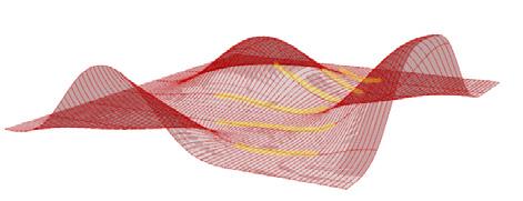
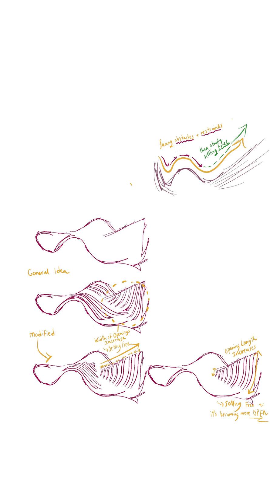
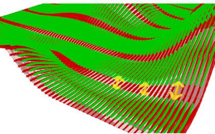
Modified Code with “Setting Free” Inspiration as Objective
Additional Parameters:
Spacing/Opening Between Strips
Number of Horizontal Strips
Number of Vertical Strips
Width of Strips
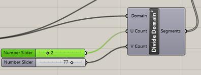
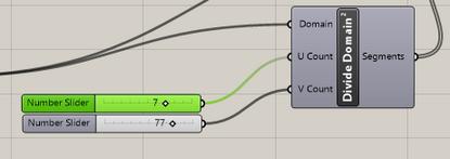
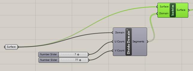
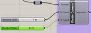
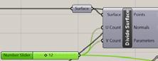
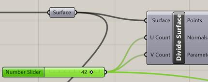
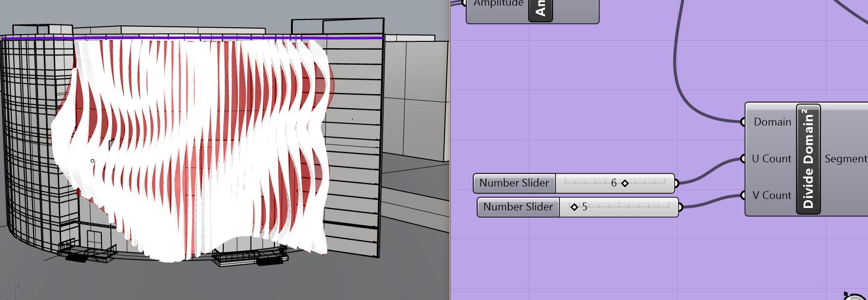
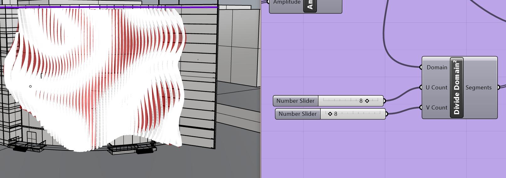
Experimenting With U Count
The less the U Count is, the less the number of horizontal strips there are.
Chapter name Portfolio 30
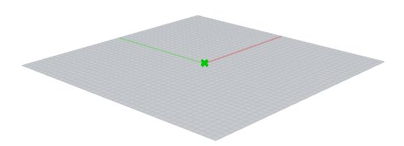
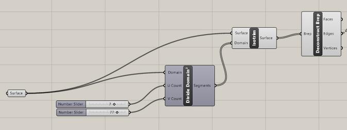
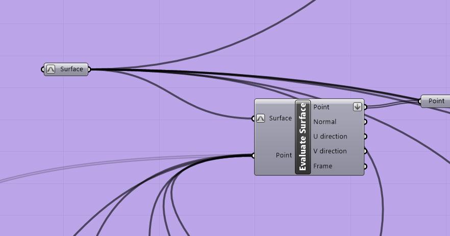
Step 2: Dividing the Surface Into Segments
Step 3: Deconstruct
Step 1: Select Rhino Surface on Grasshopper
Points Extracted for Initial Experimentation)
I then used List Item and Random Command to extract random points from the surface constructed. Objective Instead of Random Points
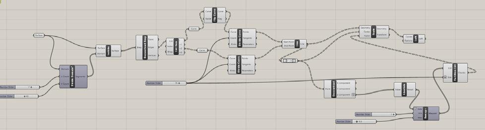

Deconstruct Brep Step 4: Divide Curve into a number N of equal length segments are.
Student Name ARCH 473/3522
Spring 2019 31
-
Segments
Edge 1
Edge 2
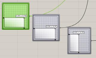
Continuation of Translation of Workflow into Grasshopper

Step 5: Line

Step 6: Point on Curve
Step 7: Scale
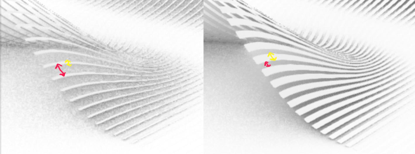
The Greater the Value is, the Greater the Distance is Between Each Curve

Step 8: Loft
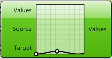
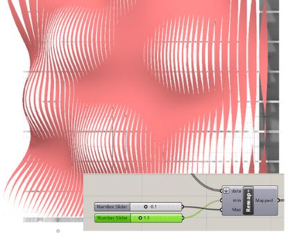
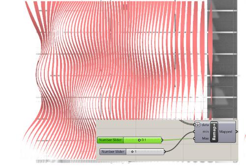
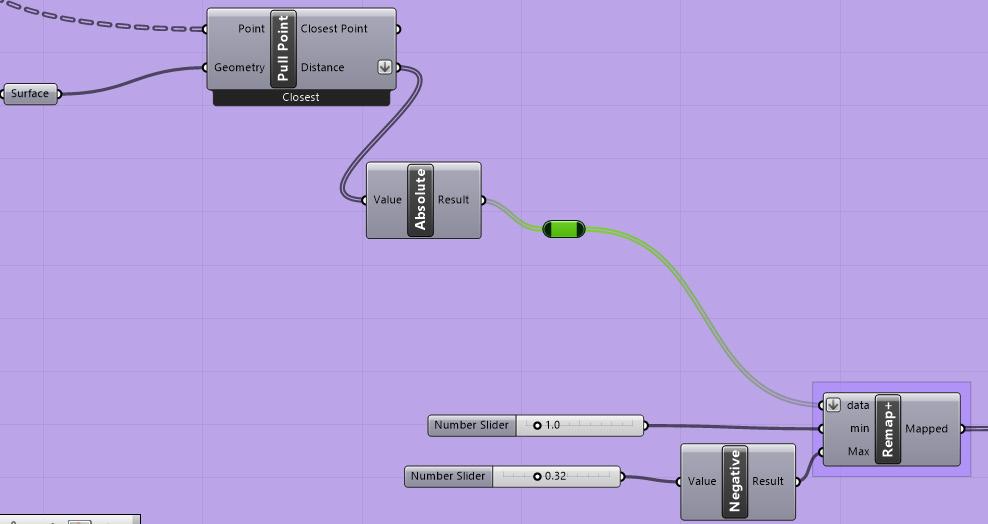
Step 9: Remap+
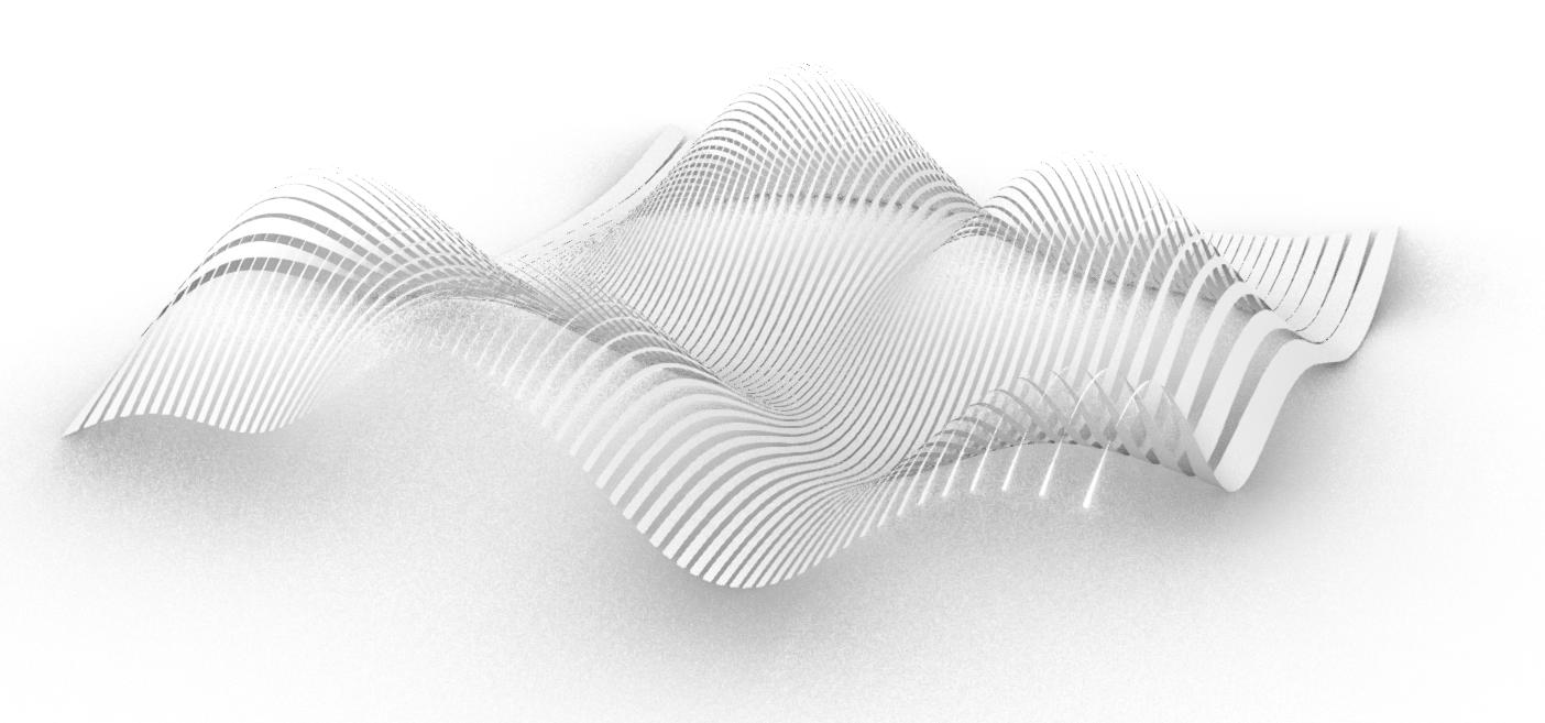
Making Spacing Between Each Strip Descending As They Get Closed to Solid Areas
More Open (Setting Free)
Similar to Objective (Sketch)
More Restricted/Closed
Chapter name Portfolio 32
Overall Reflection:
We were required to deduce the main parameters from our selected panels before applying them on Grasshopper. After identifying which parameters I will be altering, I experimented with changing each variable to see how it affected the output and how the mix between more than one variable creates a completely different form. I started with using a Rhino surface which prevented me from being able to change the parameters easily, and so I changed my code to make it entirely on grasshopper with having my main parameters of height of the curve, wavelength, number of curves, thickness of surface, distance between each curve, and width/lenght of surface.

Student Name ARCH 473/3522 - Spring 2019 33
The Greater the Factor is, the Thicker the Strip is and the Less the Opening/Spacing Between Them Is
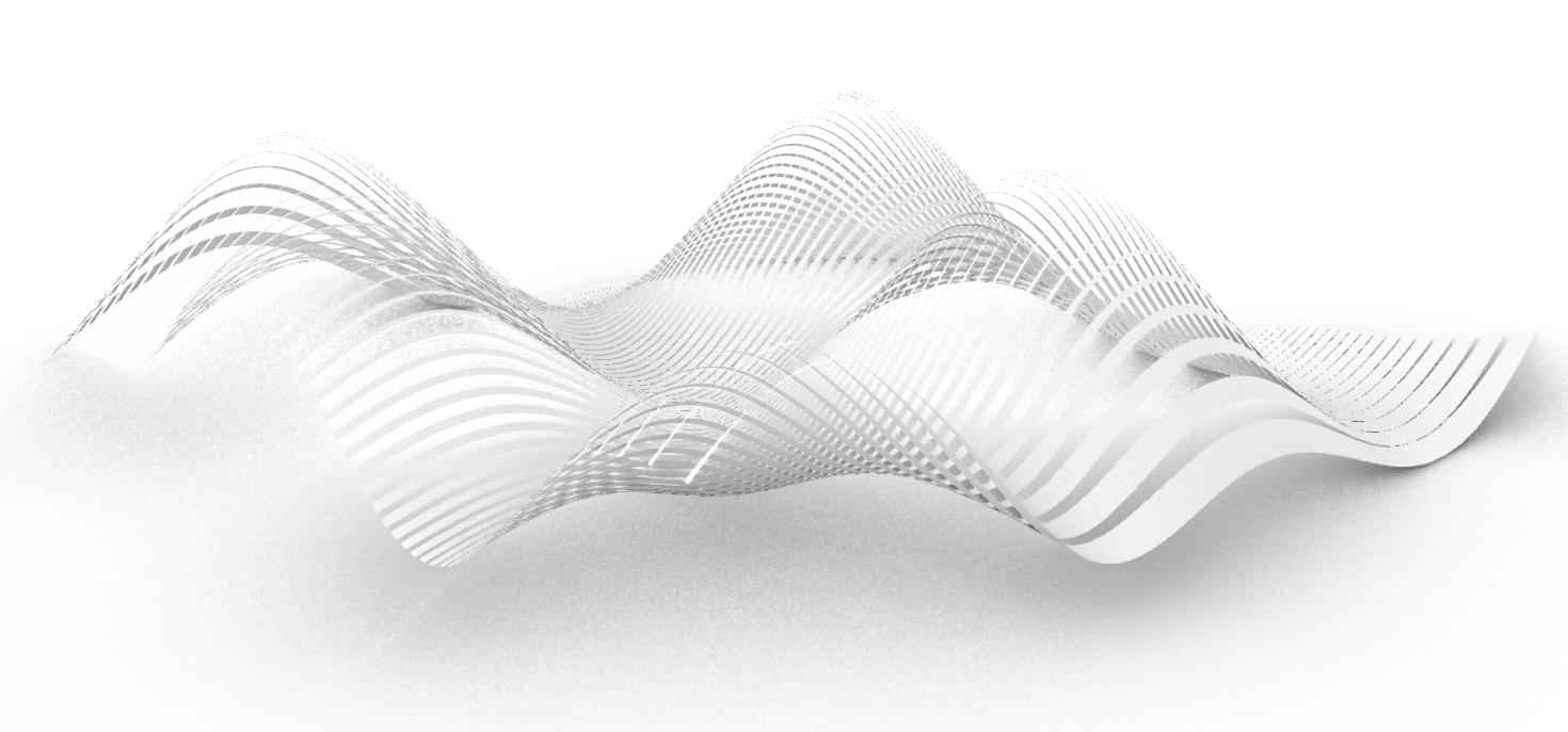
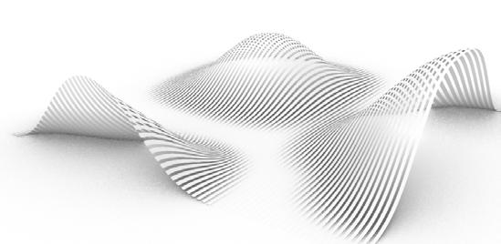
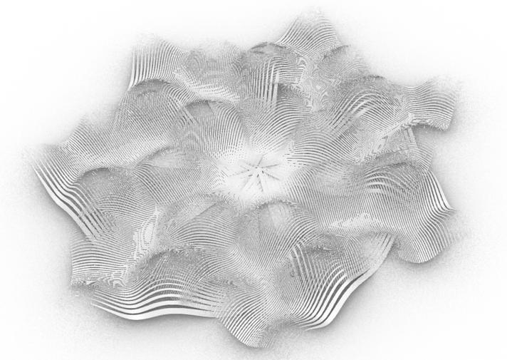
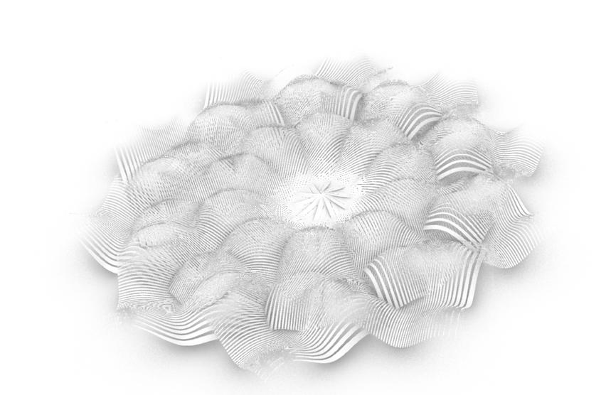
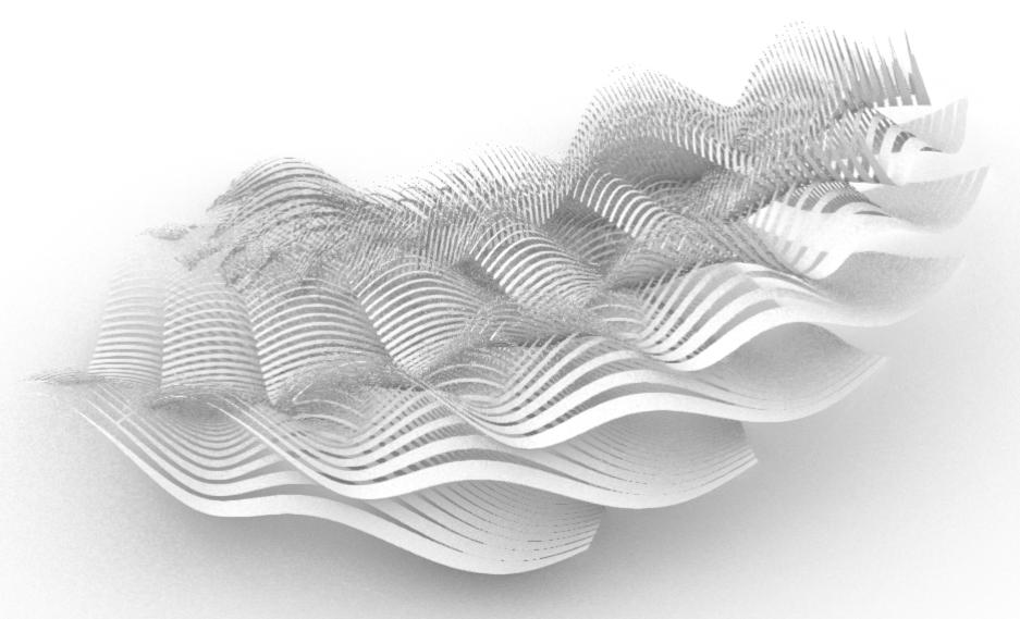
Forming a Cluster Using Different Alterations of the Single Panel Design
Project 1.4: Forming a Cluster
04
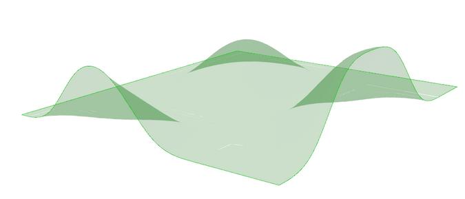
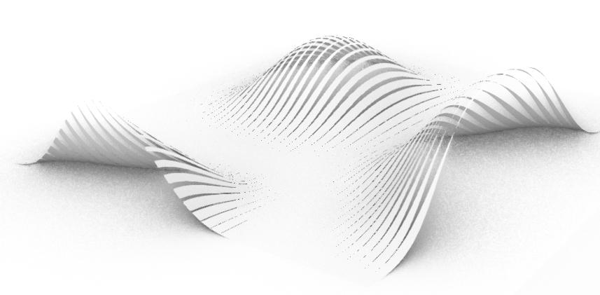
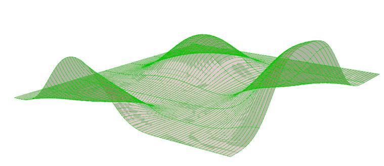
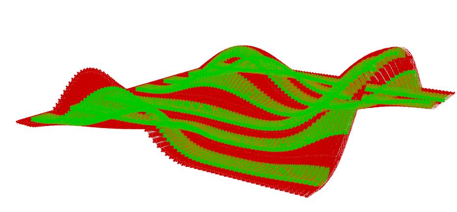
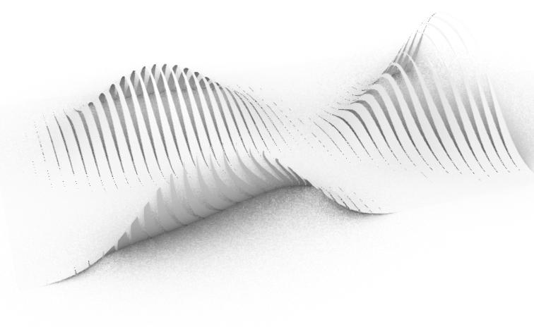
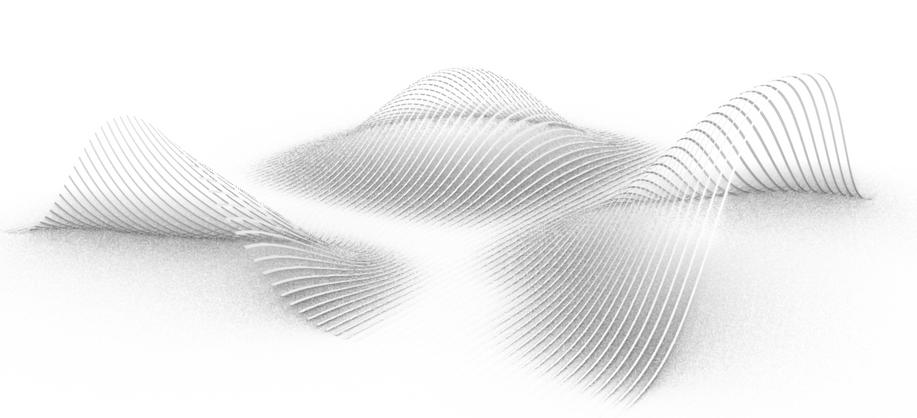
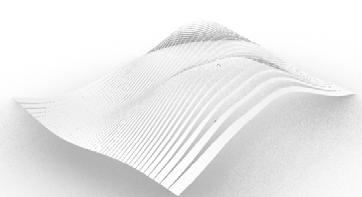
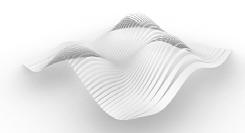
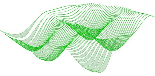
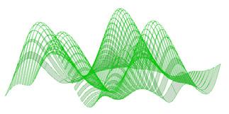
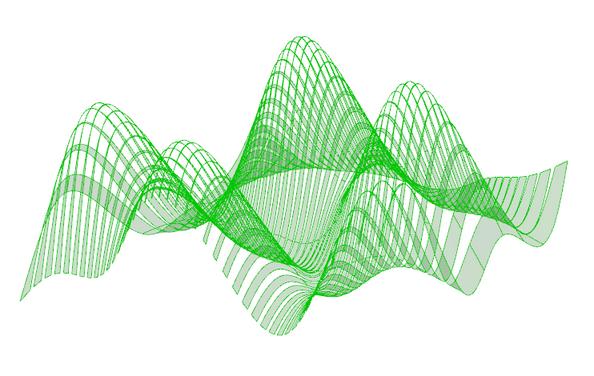
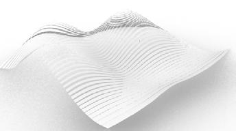
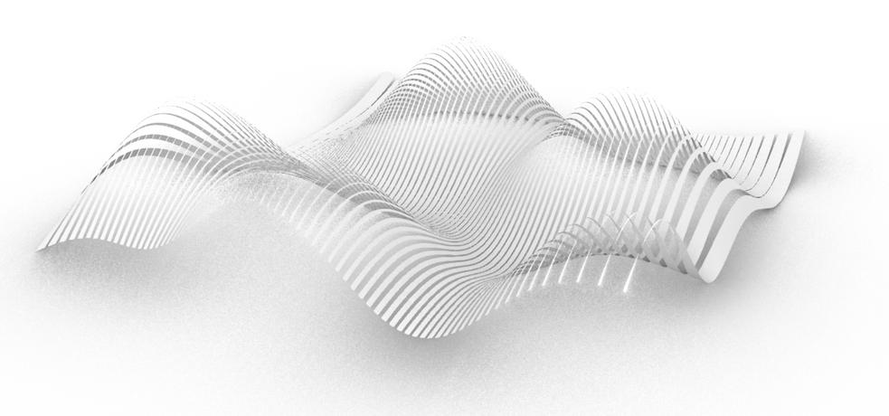
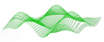
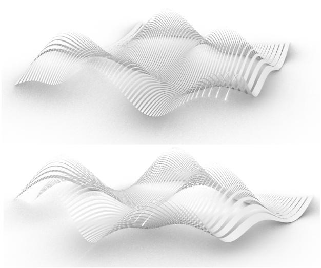
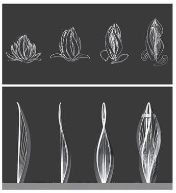
Different Iterations of Single Panel Design
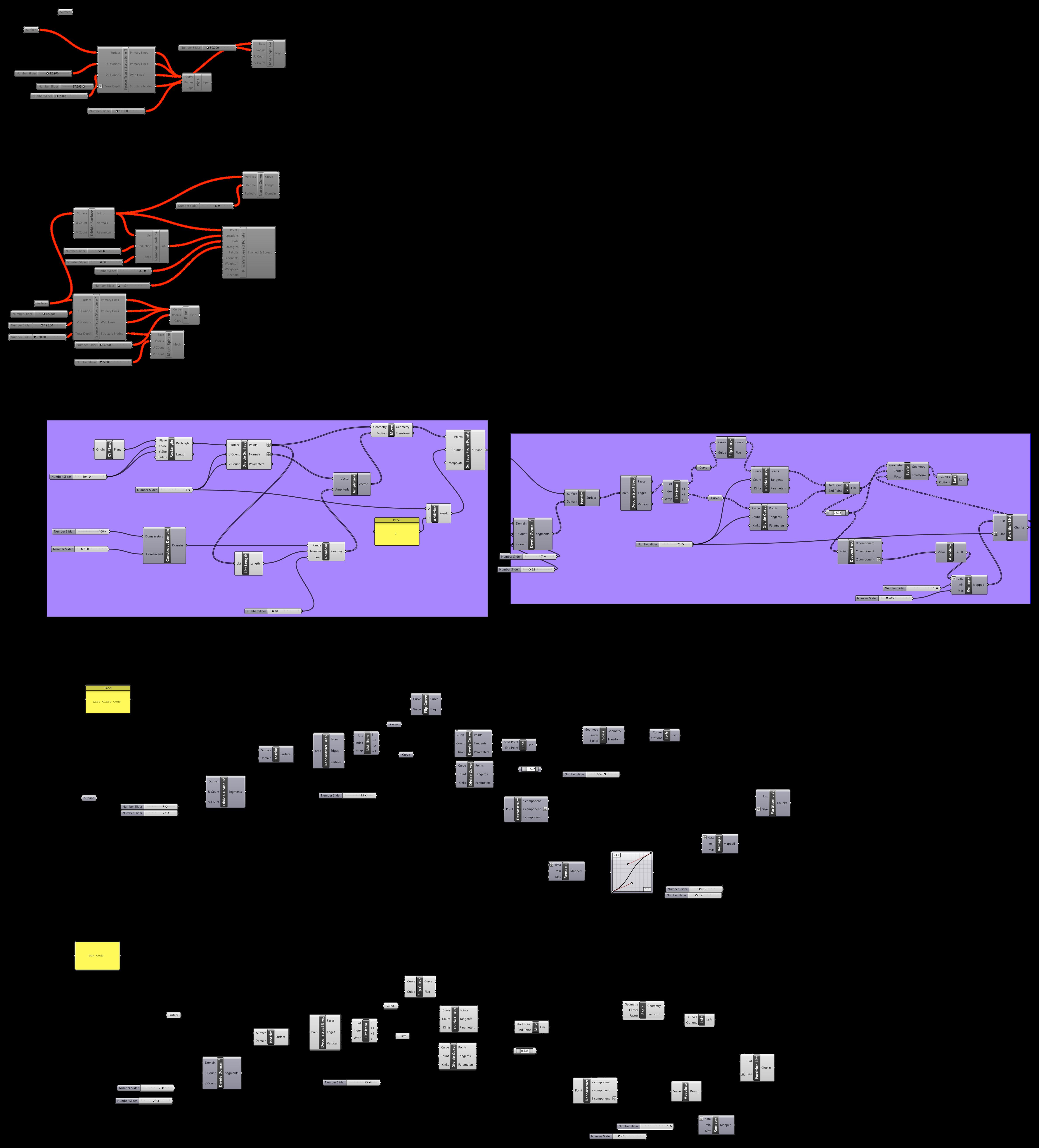
Grasshopper Code
Altered Code from Using Rhino as Initial Surface to Surface Made from
Code of Grasshopper Surface Without Random Command
Chapter name Portfolio 36
from Grasshopper (to alter more from initial curves’ parameters)
Creating Strips on Surface (No Change from Previous Code)
Student Name ARCH 473/3522 - Spring 2019 37
Different Iterations of Single Panel Design
Dissecting Each Part of the Code
D i f f e r e n t I t e r a t i o n s
D i f f e r e n t I t e r a t i o n s
D i f f e r e n t I t e r a t i o n s
O r i g i n a l
O r i g i n a l
O r i g i n a l
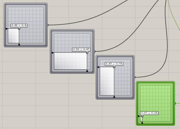
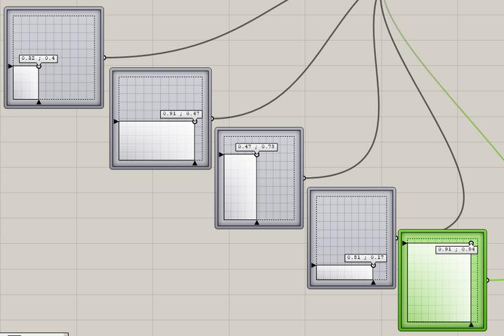
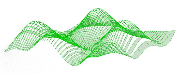
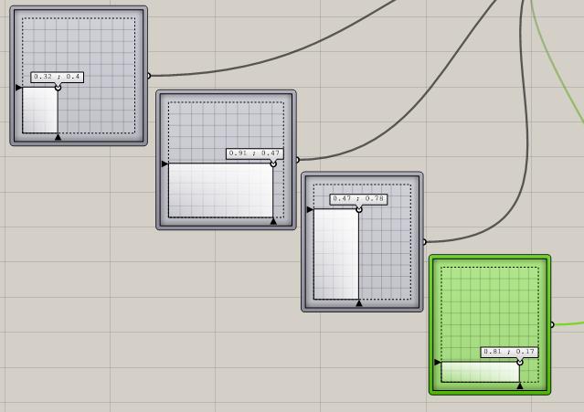
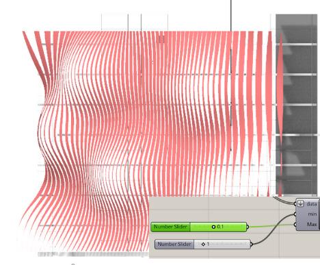
1) I changed the values of one “multidimensional slider” while keeping other two constant but it was too subtle or “calm” for the concept I was aiming for of “encountering multiple obstacles on the way before setting free”.
1 ) I c h a n g e d t h e v a l u e s o f o n e " m u l t i d i m e n s i o n a l s l i d e r " w h i l e k e e p i n g o t h e r t w o c o n s t a n t b u t i t w a s t o o s u b t l e o r " c a l m " f o r t h e c o n c e p t I w a s a i m i n g f o r o f " e n c o u n t e r i n g m u l t i p l e o b s t a c l e s o n t h e w a y b e f o r e s e t t i n g f r e e "
1 ) I c h a n g e d t h e v a l u e s o f o n e " m u l t i d i m e n s i o n a l s l i d e r " w h i l e k e e p i n g o t h e r t w o c o n s t a n t b u t i t w a s t o o s u b t l e o r " c a l m " f o r t h e c o n c e p t I w a s a i m i n g f o r o f " e n c o u n t e r i n g m u l t i p l e o b s t a c l e s o n t h e w a y b e f o r e s e t t i n g f r e e "
1 ) I c h a n g e d t h e v a l u e s o f o n e " m u l t i d i m e n s i o n a l s l i d e r " w h i l e k e e p i n g o t h e r t w o c o n s t a n t b u t i t w a s t o o s u b t l e o r " c a l m " f o r t h e c o n c e p t I w a s a i m i n g f o r o f " e n c o u n t e r i n g m u l t i p l e o b s t a c l e s o n t h e w a y b e f o r e s e t t i n g f r e e "
4 c
Alteration
A l t e r a t i o n
A l t e r a t i o n
A l t e r a t i o n
Alteration
A l t e r a t i o n A l t e r a t i o n
A l t e r a t i o n A l t e r a t i o n
Alteration
A l t e r a t i o n A l t e r a t i o n
2 ) I s t a r t e d a d d i n g m o r e " m u l t i d i m e n s i o n a l s l i d e r s " a n d c h a n g i n g t h e v a l u e s o f i t , d e m o n s t r a t i n g m o r e m o v e m e n t t o t h e s u r f a c e , w h i l e k e e p i n g o t h e r c u r v e s c o n s t a n t .
2) I started adding more “multidimensional sliders” and changing the values of it, demonstrating more movement to the surface, while keeping other curves constant.

2 ) I s t a r t e d a d d i n g m o r e " m u l t i d i m e n s i o n a l s l i d e r s " a n d c h a n g i n g t h e v a l u e s o f i t , d e m o n s t r a t i n g m o r e m o v e m e n t t o t h e s u r f a c e , w h i l e k e e p i n g o t h e r c u r v e s c o n s t a n t .
2 ) I s t a r t e d a d d i n g m o r e " m u l t i d i m e n s i o n a l s l i d e r s " a n d c h a n g i n g t h e v a l u e s o f i t , d e m o n s t r a t i n g m o r e m o v e m e n t t o t h e s u r f a c e , w h i l e k e e p i n g o t h e r c u r v e s c o n s t a n t .
c ( i
4 c ( i
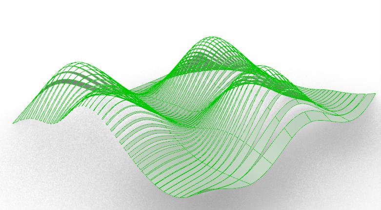
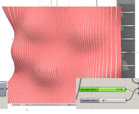
3 ) I a d d e d a 5 t h m u l t i - d i m e n s i o n a l s l i d e r a n d i t a l m o s t h a d t h e m o s t s u i t a b l e m o v e m e n t I w a s a i m i n g f o r t h a t w a s s t i l l s u b t l e a n d n o t t o o m a n y .
3 ) I a d d e d a 5 t h m u l t i - d i m e n s i o n a l s l i d e r a n d i t a l m o s t h a d t h e m o s t s u i t a b l e m o v e m e n t I w a s a i m i n g f o r t h a t w a s s t i l l s u b t l e a n d n o t t o o m a n y
3 ) I a d d e d a 5 t h m u l t i - d i m e n s i o n a l s l i d e r a n d i t a l m o s t h a d t h e m o s t s u i t a b l e m o v e m e n t I w a s a i m i n g f o r t h a t w a s s t i l l s u b t l e a n d n o t t o o m a n y
3) I added a 5th multi-dimensional slider and it almost had the most suitable movement I was aiming for that was still subtle and not too many.
Chapter name Portfolio 38
4
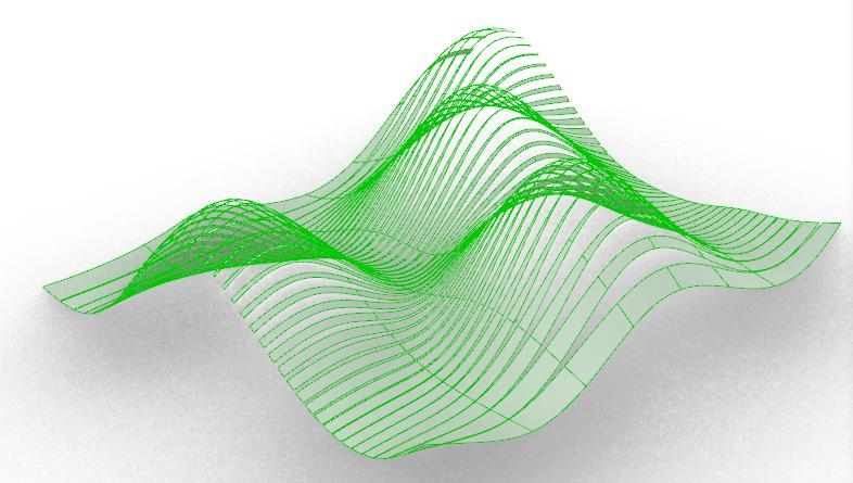
4 ) I d e c r e a s e d t h e X a n d Y d i m e n s i o n s o f t h e s u r f a c e , w h i c h i n c r e a s e d t h e h e i g h t s o f t h e c u r v e s a n d r e d u c e d t h e i r w a v e l e n g t h s , m a k i n g i t t o o d y n a m i c f o r w h a t I w a s a i m i n g f o r .
4 ) I d e c r e a s e d t h e X a n d Y d i m e n s i o n s o f t h e s u r f a c e , w h i c h i n c r e a s e d t h e h e i g h t s o f t h e d d d t h i l t h k i n g i t t o o d y n a m i c f o r w h a t I w a s a i m i n g f o r .
4) I decreased the X and Y dimensions of the surface, which increased the heights of the curves and reduced their wavelengths, making it too dynamic for what I was aiming for.
O r i g i n a l
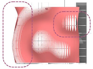
5 ) I i n c r e a s e d t h e U a n d V c o u n t o f t h e D i v i d e S u r f a c e , w h i c h a l s o d e c r e a s e d t h e w a v e l e n g t h s a n d i n c r e a s e d t h e h e i g h t o f t h e c u r v e w i t h a s h a r p e r e d g e .
5 ) I i n c r e a s e d t h e U a n d V c o u n t o f t h e D i v i d e S u r f a c e , w h i c h a l s o d e c r e a s e d t h e w a v e l e n g t h s a n d i n c r e a s e d t h e h e i g h t o f t h e c u r v e w i t h a s h a r p e r e d g e .
5) I increased the U and V count of the Divide Surface, which also decreased the wavelengths and increased the height of the curve with a sharper edge.
A l t e r a t o n
A l t e r a t o n
A l t e r a t i o n
A l t e r a t i o n
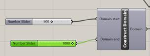
(5) I increased the domain start and end and this same form was also achieved by increasing the domain start to 1000.

(
5 ) I i n c r e a s e d t h e d o m a i n s t a r t a n d e n d a n d t h i s s a m e f o r m w a s a l s o a c h i e v e d b y i n c r e a s i n g t h e d o m a i n s t a r t t o 1 0 0 0 )
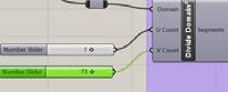
( 5 ) I i n c r e a s e d t h e d o m a i n s t a r t a n d e n d a n d t h i s s a m e f o r m w a s a l s o a c h i e v e d b y i n c r e a s i n g t h e d o m a i n s t a r t t o 1 0 0 0 ) 6 ) I n c r e a s i n g t h e V C o u n t o f t h e D i v i d e D o m a i n i n c r e a s e d t h e s t r i p e s a n d t h u s e s p a c i n g b e t w e e n t h e s t r i p s m a k i n g t h e m o o t h w h i c h f i t m o r e m y c o n c e p t o f e a s i l y
O r i g i n a l
O i i l
O r i g i n a l
O r i g i n a l
A l t e r a t i o n
A l t e r a t i o n
D o m a i n i n c r e a s e d t h e s t r i p e s a n d t h u s e s p a c i n g b e t w e e n t h e s t r i p s m a k i n g t h e c e d g a s o o e s m o o t h w h i c h f i t m o r e m y c o n c e p t o f e a s i l y t o b e i n g s e t f r e e
W h i l e t h e d o m a i n e n d i n c r e a s e r e s u l t e d i n i t s i n v e r s e s h a p e
W h i l e t h e d o m a i n e n d i n c r e a s e r e s u l t e d i n i t s i n v e r s e s h a p e
While the domain end increase resulted in its inverse shape
A l t e r a t i o n
A l t e r a t i o n
6) Increasing the V Count of the Divide Domain increased the stripes and thus decreased the overall proportion of the spacing between the strips making the spacing descending transition more smooth which fit more my concept of easily transitioning to being set free.
Student Name ARCH 473/3522 - Spring 2019 39
Alteration Original Original Alteration Alteration Alteration Original Original
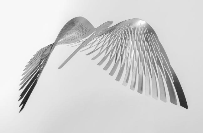
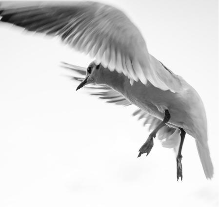
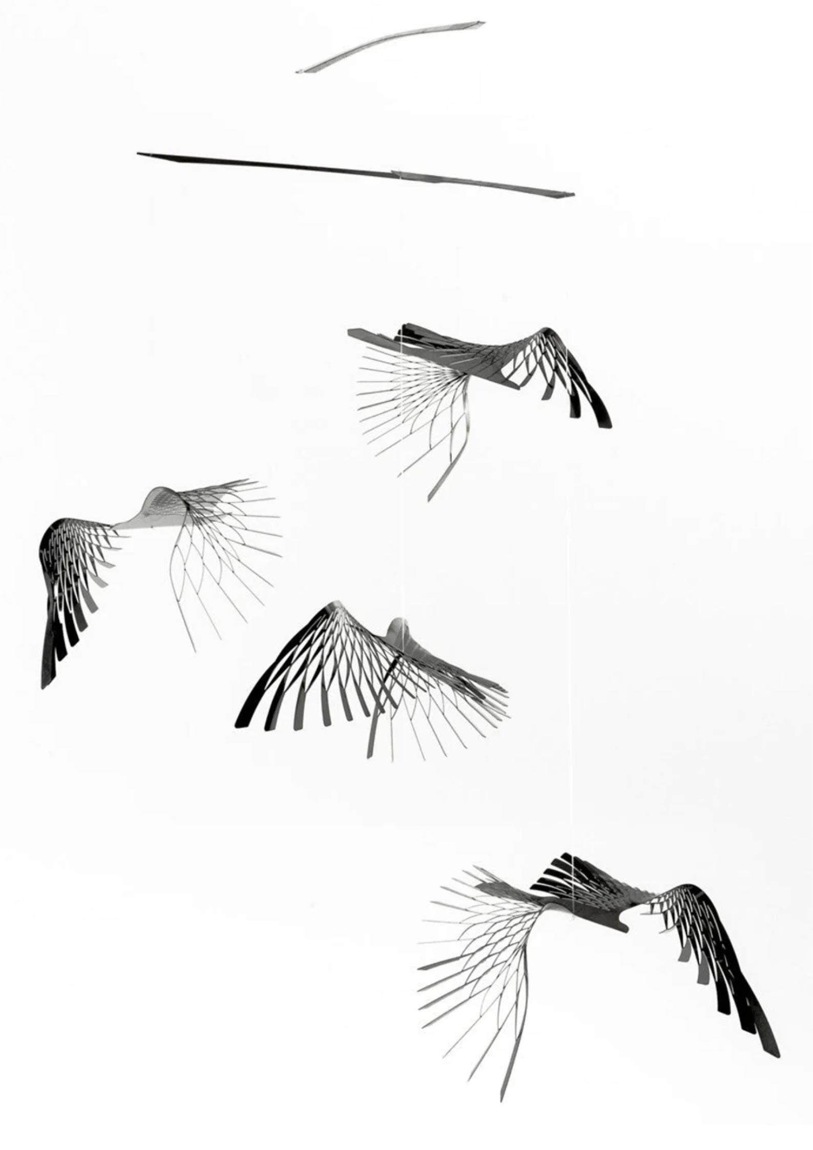
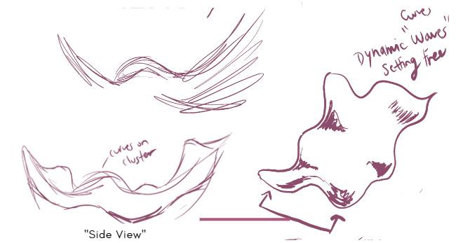
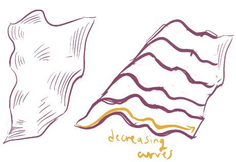
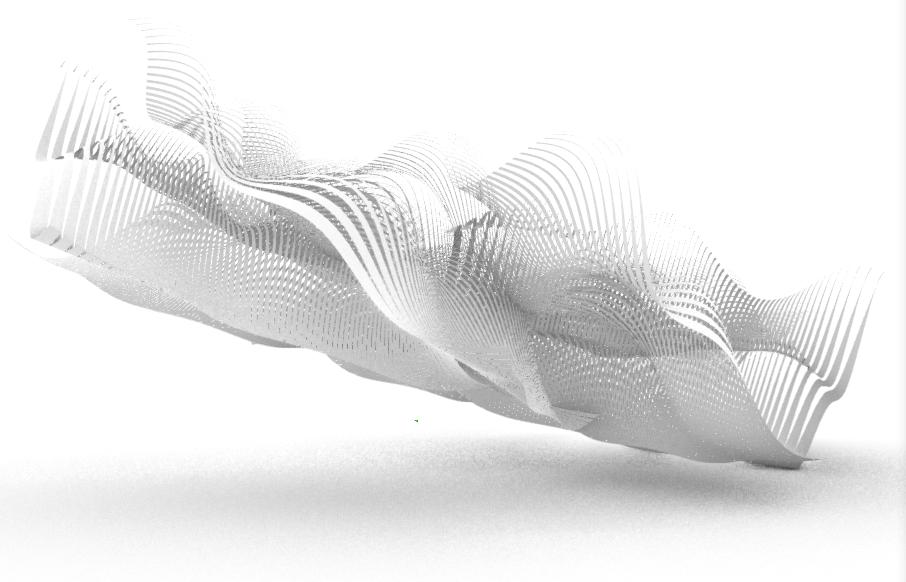
...or to make it more realistic or less “proper” similar to how the bird flies (it goes through multiple stages), one panel can be decreasing in its width while the second panel can be flipped so it’s increasing.
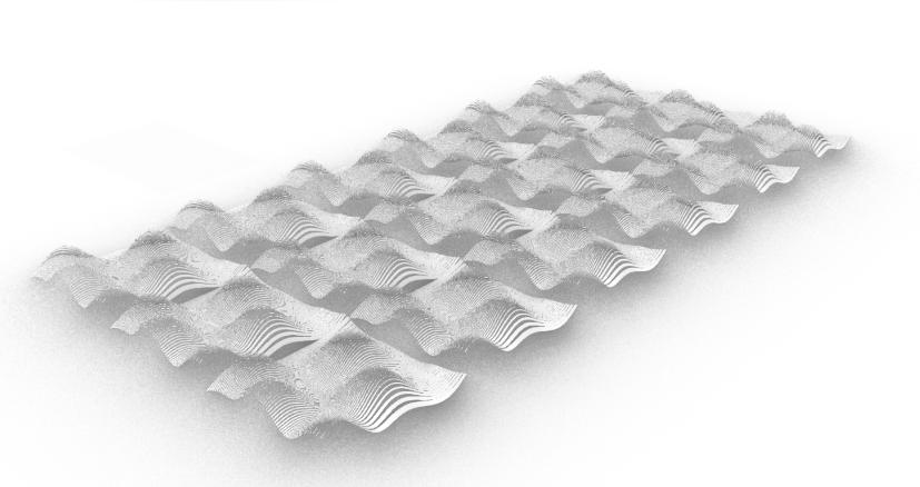
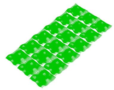
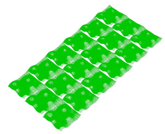
Propagation of Single Unit into Cluster of Panels
Thought Process


The plan for the cluster was initially supposed to either be a clean set (meaning straight flat edges for the overall cluster from the length (long side) while only the width is dynamic showing the decreasing curves as if the strips in them are “setting free” after their encountered obstacles.
...or the whole cluster can be dynamic in which the edges of the entire system is curvilinear instead of straight .
Chapter name Portfolio 40 Material Exploration Learning from Materiality
Local Parameters Global Parameters
Surface Width & Length
Curve Wavelength
Curve Height
Number of Curves
Distance Between Curves
Thickness of Surface
Spacing/Opening Between Strips
Number of Horizontal Strips
Number of Vertical Strips
Width of Strips
Rotation of Panel
Scale of Panel
Array Type (Rectangular, Polar, Etc)

True/False in Panels
Angle Count
Student Name ARCH 473/3522 - Spring 2019 41 Fall 2022 Fall 2022 ARCH 473/3522 - Fall 2022
Propagation of Single Unit into Cluster of Panels
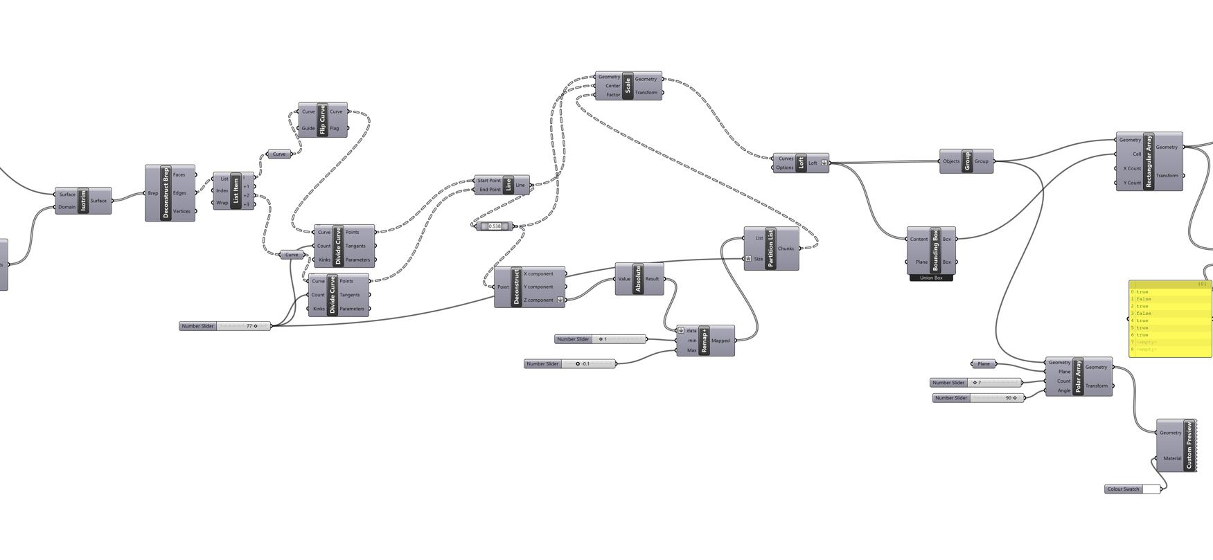
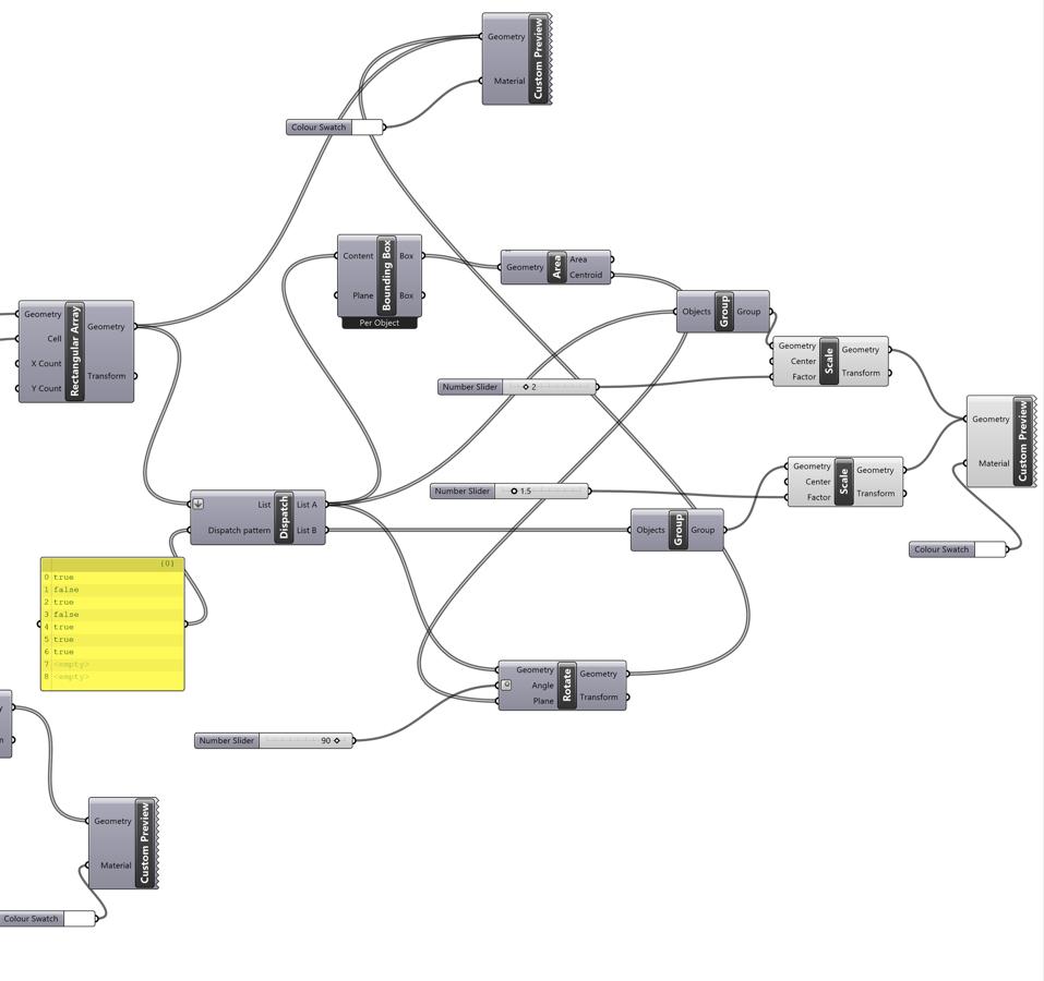
Grasshopper Code
Chapter name Portfolio 42 G r a s s h o p p e r D e f i n i t i o n
Additional Part of Code for Cluster Forming
Student Name ARCH 473/3522 - Spring 2019 43
Propagation of Single Unit into Cluster of Panels
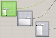
Dissecting Each Part of the Code
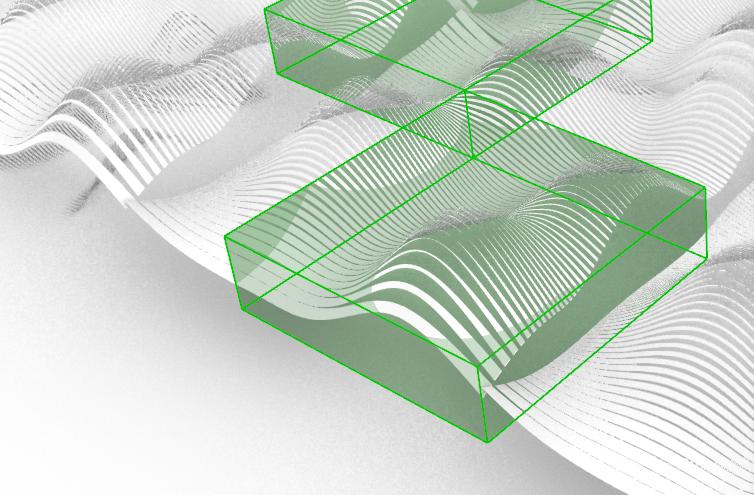
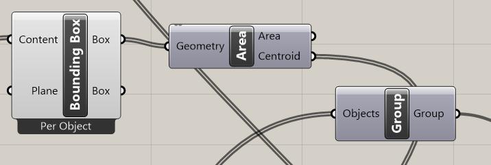
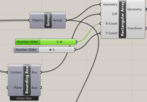
1) Grouped Objects, Created Bounding Box as Union Box (to determine panel area) & Rectangular Array

Original
Alteration
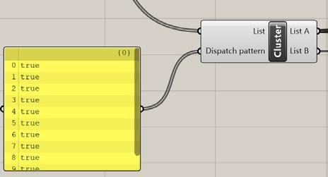
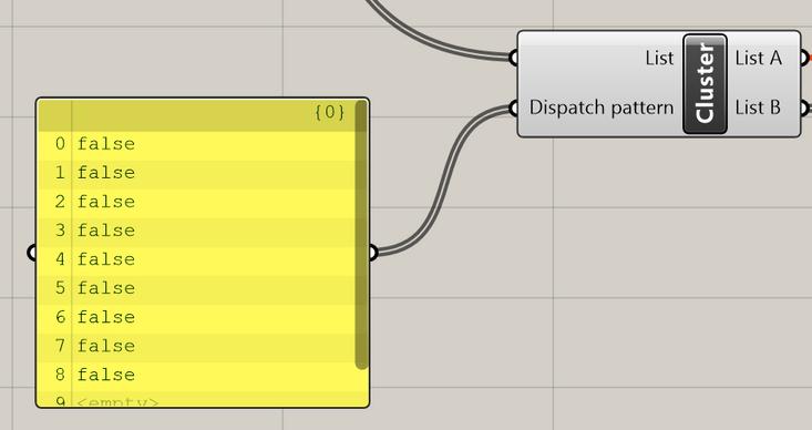
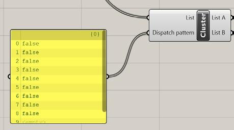
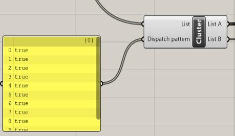
2) Changing True/False in Panels Changes Their Direction
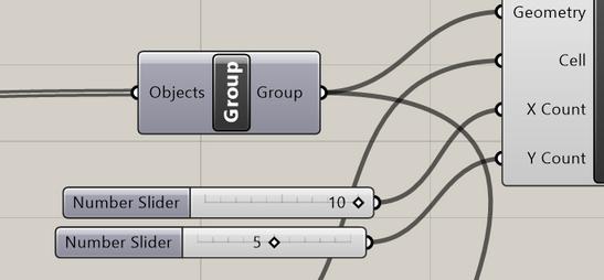
Parameters Changed: X and Y Dimensions of Array (X and Y Count / Number of Panels in X and Y)

3) Create another Bounding Box from Cluster List


Chapter name Portfolio 44
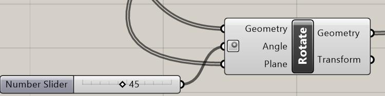
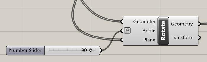
4) Rotate Panels
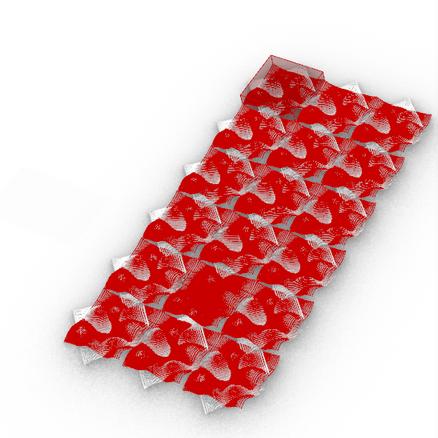
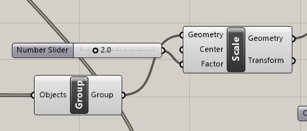
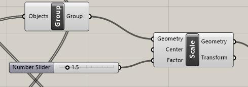
5) Scaling
6) Use Polar Array Instead of Rectangle Array
Scale Few Panels - Factor of 1.5
(Variations of this type shown in next poster)
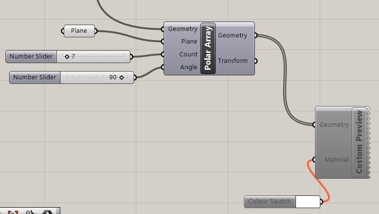
7) Custom Preview & Color Swatch for Materiality & Color
Student Name ARCH 473/3522 - Spring 2019 45
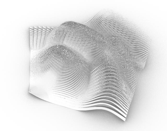
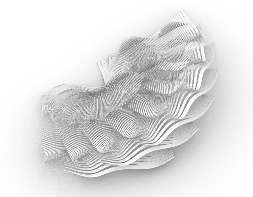
Cluster Design
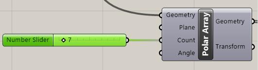
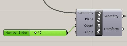
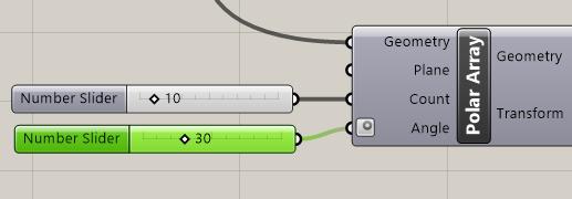
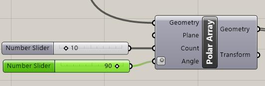
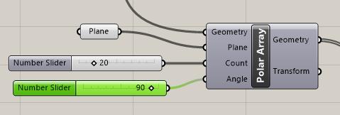
Polar Array Count
Change in Count (decreasing value) of Polar
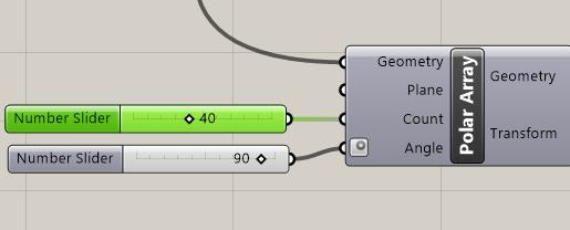
Polar Array - Angle
Addition of Angle Value of 90 degrees (constant is count of 10)
Change Angle Value (constant is count of 10)
Change Count and Angle Value
Chapter name Portfolio 46
Polar Array - Plane
Addition of Plane
Polar Array - Combining Parameters
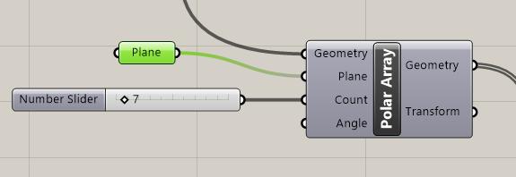
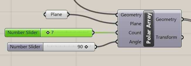
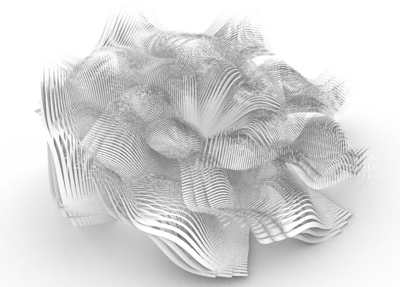
Change Count (constant plane & angle)
Student Name ARCH 473/3522 - Spring 2019 47
Continuation of Cluster Design
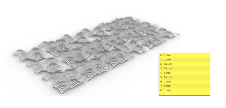
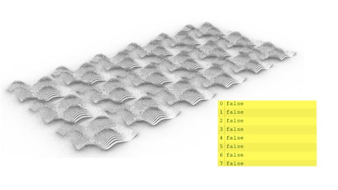
Rectangular Array - True/False Panels
Personal Reflection:
I aimed at making an array in my code initially after the rectangle surface I created as I wanted to be able to alter the local parameters on a global cluster scale, yet I would’ve had to unflatten the points and normal in the Divide Surfaces command and that would’ve removed the curves in my code, so my only option was to include the array at the end of my code which didn’t give me enough flexibility for local alterations in the cluster or to start a new code which is what I aimed at doing yet didn’t continue as I would’ve had to repeat many steps to achieve same old similar single unit.
Chapter name Portfolio 48
All True - no change of panels (rotated)
All False - all panels changed Mix True/False - Mix Changes
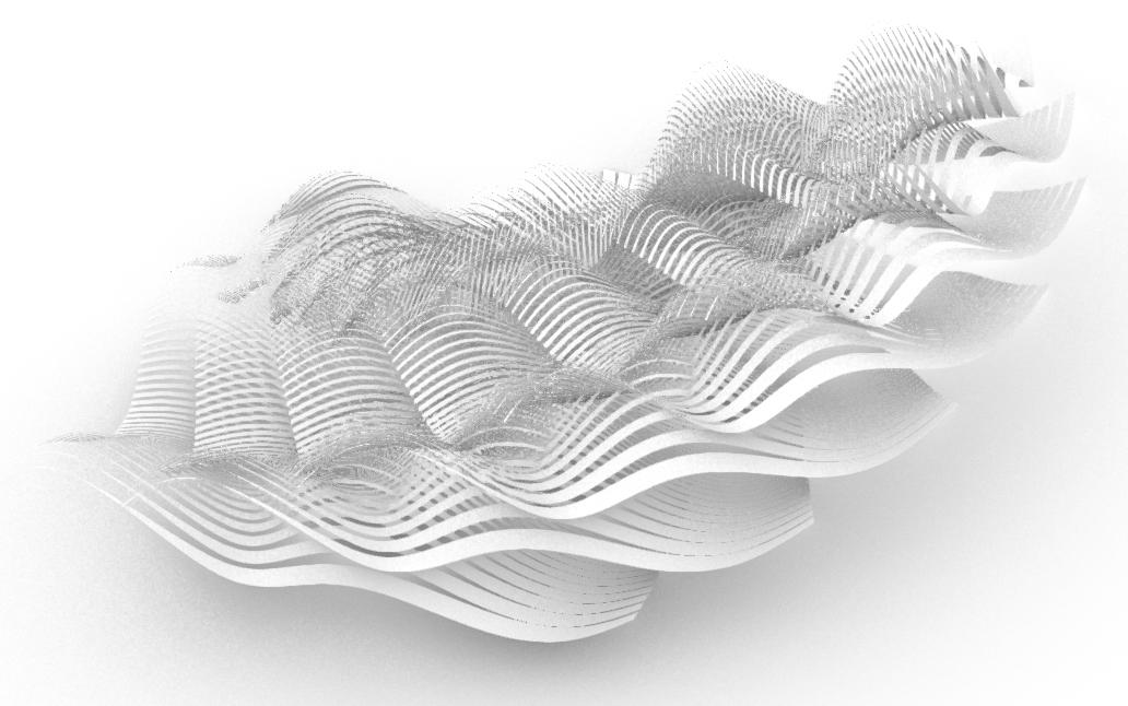
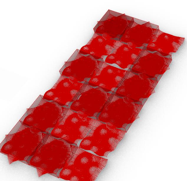
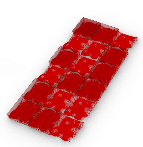
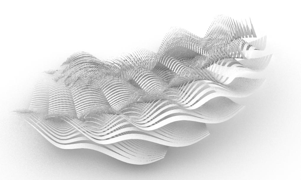
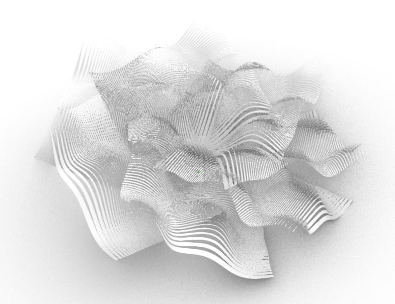
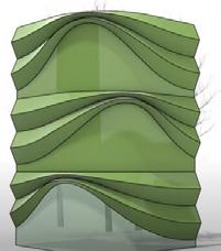
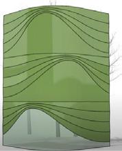
Chosen Cluster:
The reason for this selection is that the overlapping of the curves on top of each other as they’re laid out on the z axis using the plane as an input gives a “growing” which is similar to the “diverging” concept. The remaining overlapping of panels portray the obstacles they encounter, yet in a manner of rhythm & flow, meaning they’re “setting free”. This is the closest cluster that resembles my concept until I can redo the whole code using an array (for clustering) to be included in the beginning of the code.
Student Name ARCH 473/3522 - Spring 2019 49
Divide Surface Command (Flattened) in Grasshopper Code That Prevented Me From Having Flexible Alterations
Continuation of Cluster Design
Future Suggestions
Starting a New Code for Greater Flexibility in Cluster Design as I Had in Initial Single

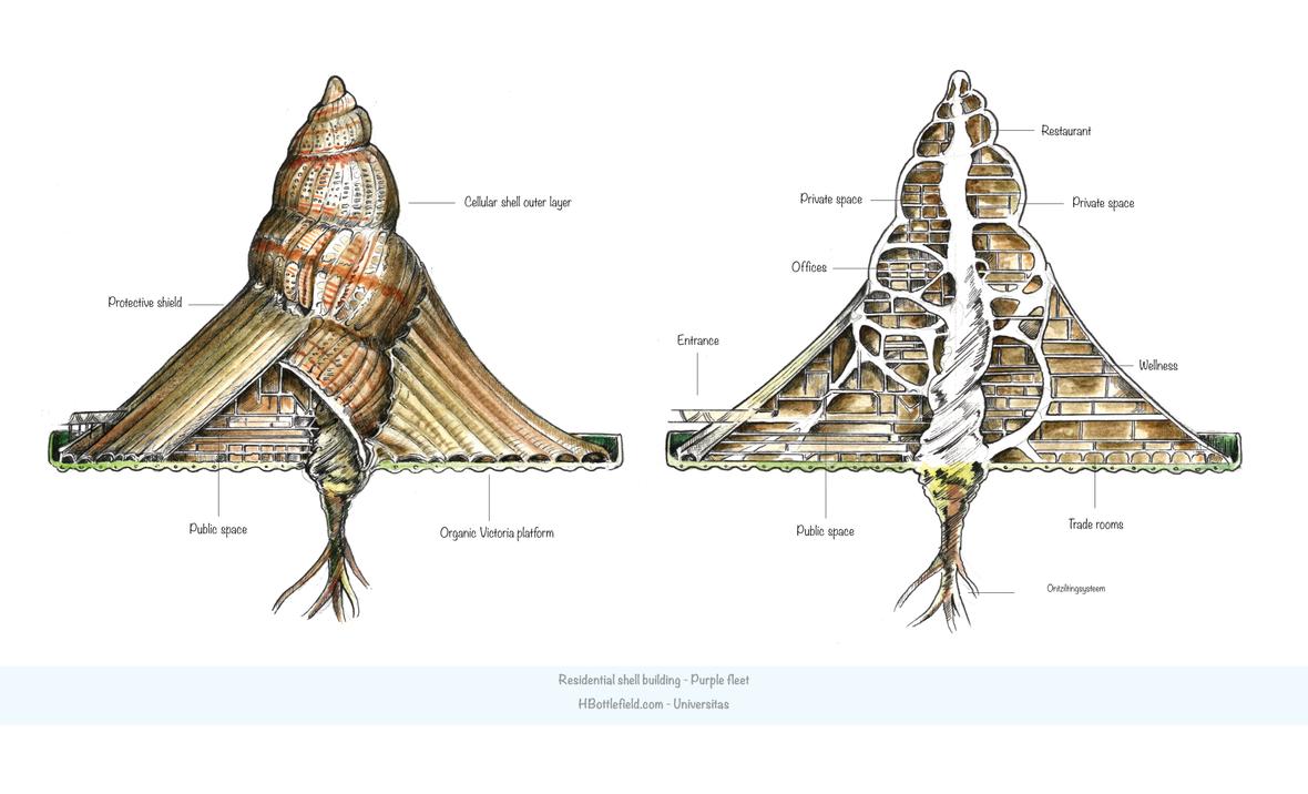
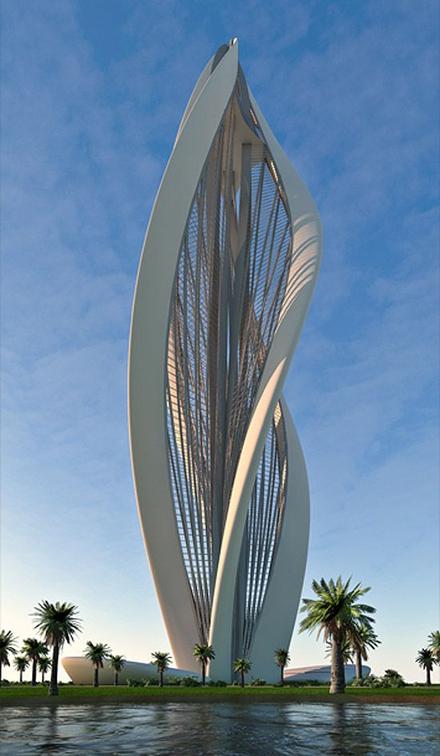
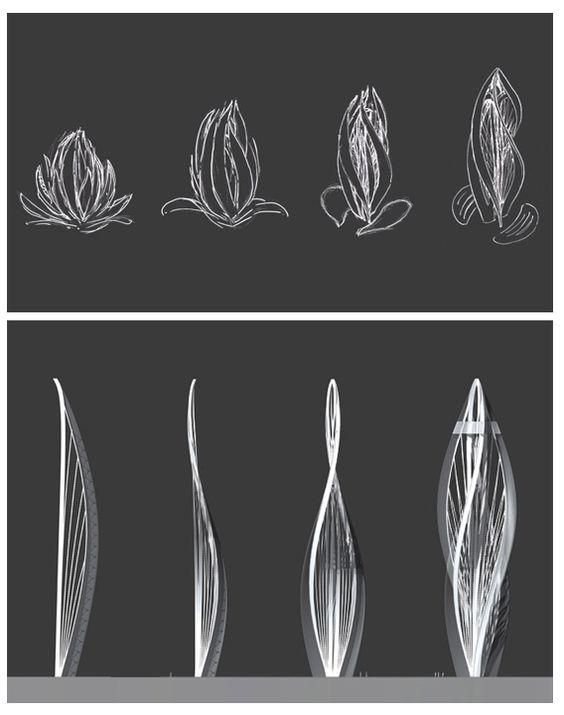
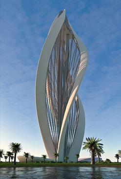
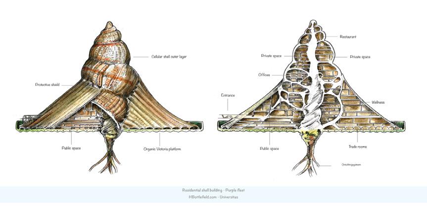
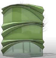
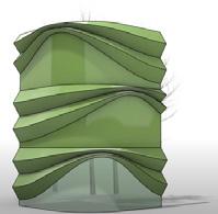
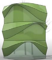
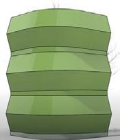
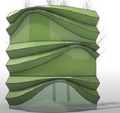
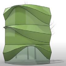
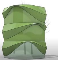
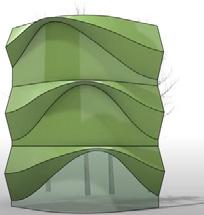
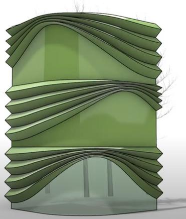
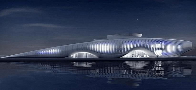
Panel “Blossoming Dubai” to the Zaabeel Park Tall Emblem Structure Competition. General Shape is Used for Towers https://mymodernmet.com/modern-architecture-2/ https://hbottlefield.com/universitas/chapter-3/sea-shell-buildings.html
Chapter name Portfolio 52 Material Exploration Learning from Materiality
Student Name ARCH 473/3522 - Spring 2019 53 Fall 2022 Fall 2022 ARCH 473/3522 - Fall 2022
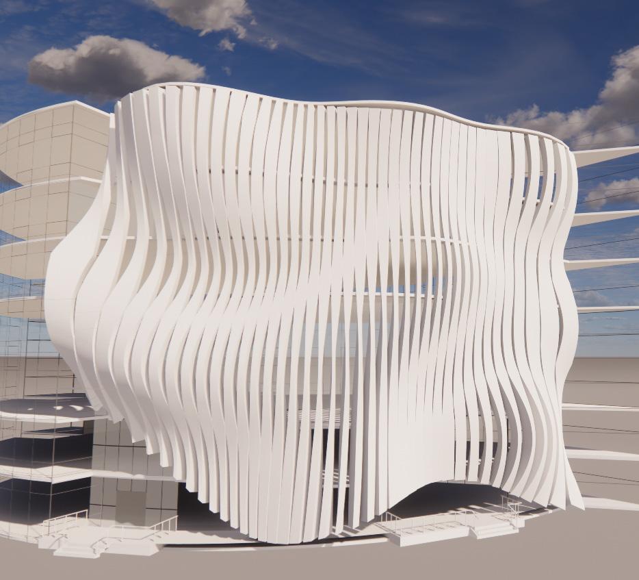
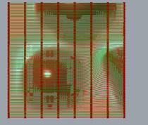
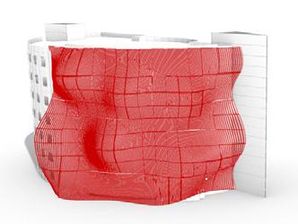
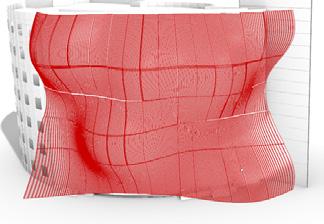
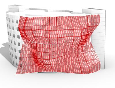
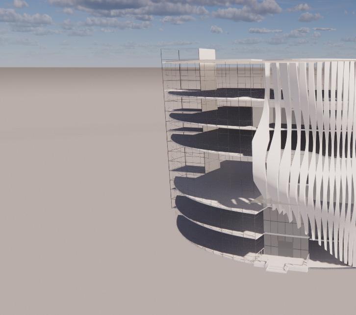
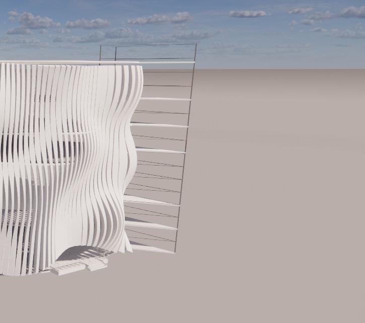
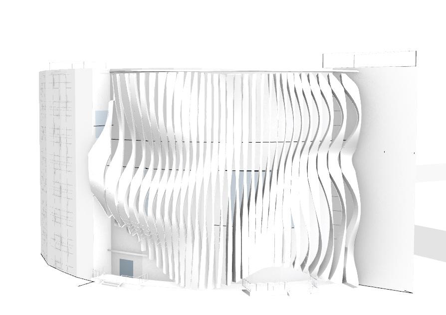
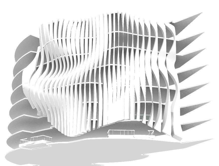
This is a shot taken on Enscape of the facade during it’s process where was still not enough variety visible in the openings.
Project 2.1: The Parametric Facelift
05
Stage 1 Double Skin Facade Research
Basic Concepts & Approaches Related to Double Skin Façades
increases efficiency of using solar energy
Precedents
https://www.sciencedirect.com/topics/engineering/double-skin-facade
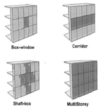
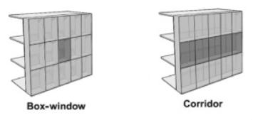
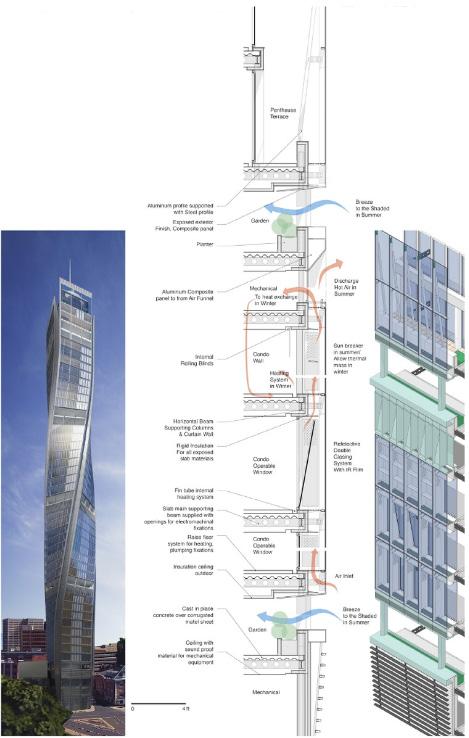
A double skin façade system includes the most advanced states of direct passive systems for maximum use of solar energy for providing a heat load & preventing thermal energy loss in buildings. It lowers thermal energy waste, increases efficieny using solar energy, has good facade sound insulation levels, creates reduction in heating and cooling consumption, and has high protection against air pollution. Regarding the double skin facades, the different types are box-window, corridor, shaft-box, and multi-storey (Fig. 5).
https://www.sciencedirect.com/topics/engineering/double-skin-facade
Box windows have single glazed external skin and openings allowing ingress of fresh air & egress of vitiated air, ventilating intermediate space & internal rooms cavity commonly used in situations in high external noise levels. The corridor type of façade has a cavity separated storey by storey with bulkheads and air is exchanged either vertically at floor level, horizontally at corners of building, or both vertically & horizontally. The shaftbox has an intermediate space between inner & outer layers and is adjoined vertically & horizontally by number of rooms. Its ventilation occurs via large openings near ground floor & roof.
...creates a suitable thermal resistance between inner & outer environment of building, and heated air in middle part is naturally used by opening windows on inner skin. Learning from Materiality
Chapter name Portfolio 56 Material Exploration
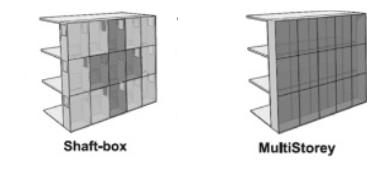
Fig. 5 Classified According to Type of DSF Building
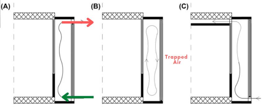
Fig 6. Type of Air Flow in Gap
Technique
During the heating period, the façade space closes at the top & bottom to optimise solar energy gains. The multi-storey type has a cavity that is not partitioned either horizontally or vertically, forming one large volume. It also has an outdoor façade that’s composed exclusively of pivoting louvers rather than traditional monolithic façade with openings. The double skin facades also vary dependent on the type of air flow in the gap (Fig. 6), in which type A (Open Natural Convection) is air circulated in the middle cavity due to buoyancy effect, the entrance of air is located in lower part of outer skin or on its lower surface, and the exit is located in the upper part of the outer skin or on its upper surface. This creates a suitable thermal resistance between inner & outer environment of building, and heated air in middle part is naturally used by opening windows on inner skin. Type B (Closed Natural Convection) works by natural convection, but the air is trapped in space between two crusts since thermal flows of inner & outer crust are different, air circulates naturally in middle gap. Natural ventilation does not happen in this method because of the closed middle cavity. The last type (Forced Convection) has air heated in the middle gap sent to room space or building entrance with a fan and the system acts as a preheater for the air.
Student Name ARCH 473/3522 - Spring 2019 57
Fall 2022 ARCH 473/3522 - Fall 2022
Stage 1 Double Skin Facade Research
Environmental Performance Especially in Hot Arid Climates
increases efficiency of using solar energy
Precedents
https://www.sciencedirect.com/topics/engineering/double-skin-facade
In hot climate, the double skin façades introduce excessive glare at certain times of day. The solutions are solar shading systems, louvers as a solar shading techniques, and horizontal louvers for providing solar shading in south facades (hot & Mediterranean climates). Double-skin façades are adaptable to cooler & warmer weather. It is this versatility that makes them so interesting: through minor modifications, such as opening or closing inlet or outlet fins or activating air circulators, the behavior of the façade is changed.
https://www.sciencedirect.com/topics/engineering/double-skin-facade
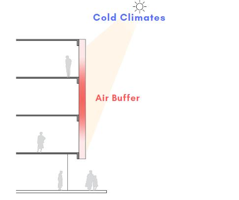
The affected design parameters are shape, position, size, inclination angle distance from facade, shape, color, & material. In cold climates (Fig. 7), the air buffer works as a barrier to heat loss. Sun-heated air contained in cavity heat spaces outside glass, reducing demand for indoor heating systems. In hot climates, cavity vented outside building to mitigate solar gain & decrease cooling load. There’s excess heat drained through chimney effect process (differences in air density create circular motion causing warmer air to escape). As air temp. in cavity rises, it’s pushed out, bringing breeze to surroundings while isolating against heat gain.
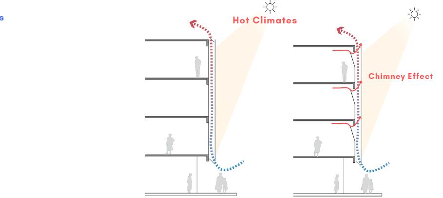
...creates a suitable thermal resistance between inner & outer environment of building, and heated air in middle part is naturally used by opening windows on inner skin.
from Materiality
Chapter name Portfolio 58 Material Exploration
Fig. 7 Cold Climates
Fig. 8 Hot Climates
Portfolio
Learning
Different Approaches for Design & Operation of Relevant Double Skin
Application in Own Design
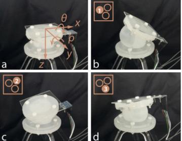
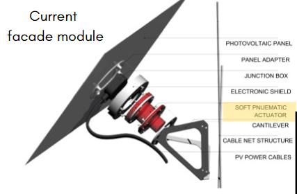
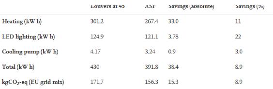
In this example in Geneva, Switzerland, simulation results on photovoltaic power production & building energy consumption was extracted, achieving total energy savings of 56% compared to no shading case & 24% compared to fixed louvers case and a reduction in electricity consumption compared to fixed louvers case by 8.9%. The parameters used for the energy simulation inspired me to also put a set point of temperature in which my facade can close or open when it reaches this limit so the facade can be responsive to the temperature.
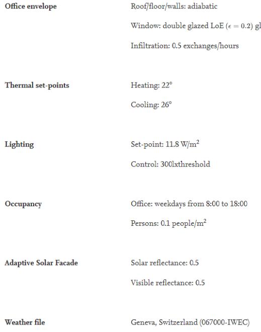
https://www.sciencedirect.com/science/article/pii/S2095263516300048#f0030
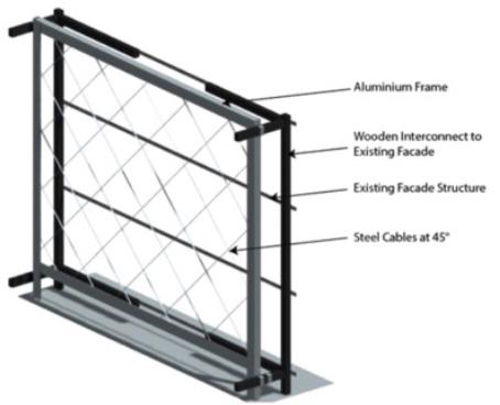
Approach 1: The Adaptive Solar Facade Design Process
https://www.sciencedirect.com/science/article/pii/S2095263516300048#f0030
Mechanical Process & Simulation Results
Student Name ARCH 473/3522 - Spring 2019 59 Fall 2022 ARCH 473/3522 - Fall 2022
Stage 1 Double Skin Facade Research
Relevant Examples and Precedents
Precedents
increases efficiency of using solar energy
This solar responsive facade has triangular forms of windows limit glazed area to 1/4 of wall surface keeps the heat in, while triangular-shaped openings let in light where needed most—near ceiling and adaptive ventilation, adaptive lighting, interactive heating and cooling systems, and effective daylighting. The Shari-f-ha House has its system & control type motorized mechanism & BMS control, the design purpose is building movement shading element and the structure is steel .
https://www.sciencedirect.com/topics/engineering/double-skin-facade
System & Control Type: Light SensorsCentral Control
Design Purpose: Shading by External
Façade Elements
Element Material: Metal Track & Sun Screen
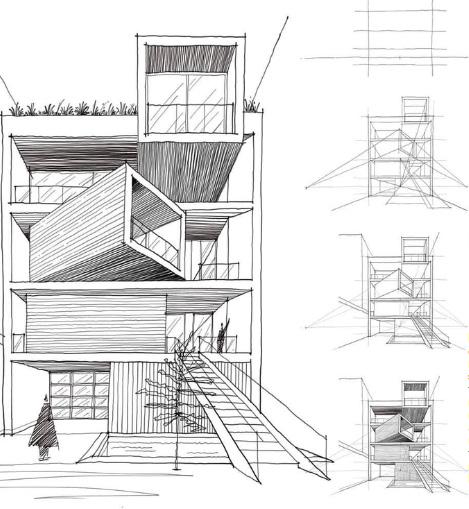
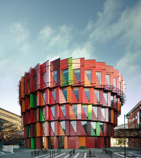
Kinetic Strategy: rotational kinetic shading strategy via solar tracking movable sun screen that rotates around top floors of circular building, designed to be photovoltaic shade screen, & its motion is responsive to sun ray’s movement around building throughout the day.
https://www.sciencedirect.com/topics/engineering/double-skin-facade
Chapter name Portfolio 60 Material Exploration
Kuggen Building, Sweden
Sharifi-ha House, Iran
https://www.sciencedirect.com/topics/engineering/double-skin-facade
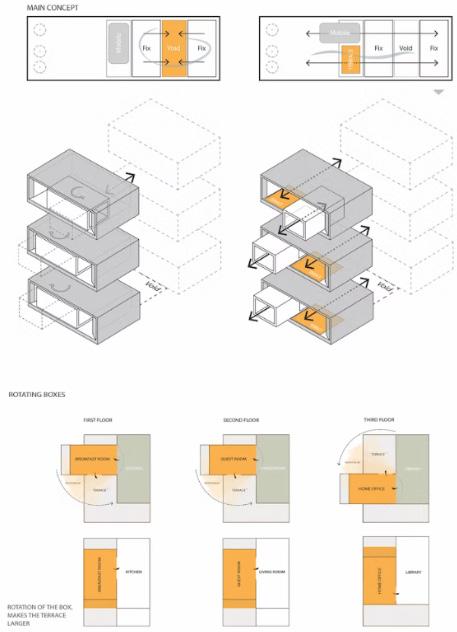
The kinetic strategy is that the building volume can open & close in response to solar radiation through movement of motorized sliding & rotating mechanism of three clarified rectangular blocks. Regarding the critique of affordances and limitations of double-skin facade systems, they have much higher initial cost of construction, space consumption, maintenance demand, may fail to function properly if context changes significantly (shading by other buildings, for instance), fire protection is an issue, reduction of rentable space, extra maintenance and operational costs, overheating issues, higher air flow velocity, more weight to structure, daylight hindrance, and acoustic insulation.
https://www.sciencedirect.com/topics/engineering/double-skin-facade
Student Name ARCH 473/3522 - Spring 2019 61 Fall 2022 Fall 2022
Stage 1 Double Skin Facade Research
Basic Understanding of Relevant Technical Details
Precedents
increases efficiency of using solar energy
This double skin facade allows for stack ventilation and the concern tackled was to block sunlight in summer coming from east, south, west facades (and horizontal shaders to block south light) & allowing sunlight to enter from same facades in winter to warm up internal space..
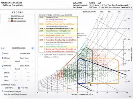
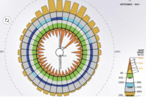
Basic Analysis of Site Conditions & Environmental Factors
https://www.sciencedirect.com/topics/engineering/double-skin-facade
Most Needed Design Strategies:
Internal Heat Gain (32.2%)
Use of natural ventilation cooling (21.8%)
Passive solar direct gain high mass by 12.9%
Chapter name Portfolio 62 Portfolio Material Exploration
Technique Fall
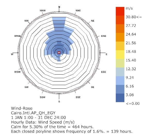
In summer during September-May, primary wind direction is North & North West while secondary wind direction is North East. Primary wind speed is North/North West & secondary wind speed is South West
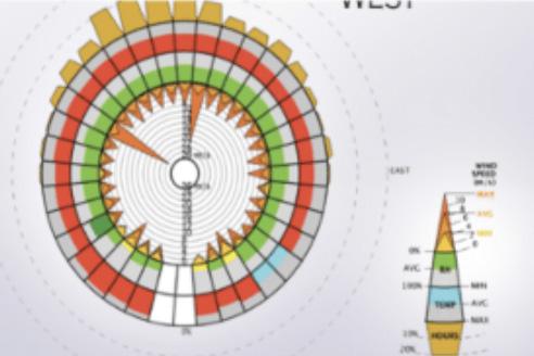
In winter, primary wind direction is North - North West & secondary wind direction is North West.
Insufficient sunlight in December & shading is needed during July, August, September, October & November. During Winter, sunlight is needed & during April, May and June, shade is needed due to amount of heavy sunlight. Increase in natural ventilation is needed & need to reduce heat gain, humidity, & direct sunlight.
Student Name ARCH 473/3522 - Spring 2019 63 Fall 2022
2022
Cluster Design
(recalling that for proper clustering with alterations of each single form/panel, new complex code should be done from scratch)
Stage 1
Double Skin Facade Research
Conceptual Idea for Design of Double Skin Façade & Choice of Operational Mechanism of Facade (Static/Responsive)
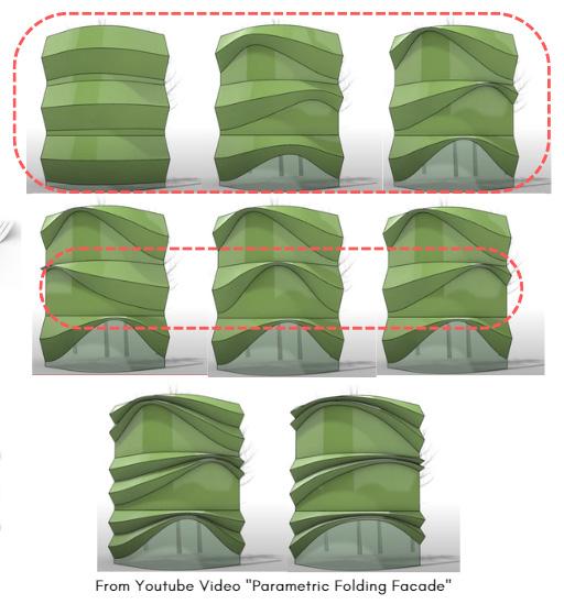
Responsive System Inspiration 1
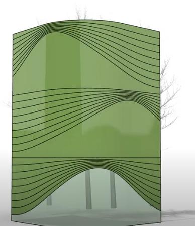
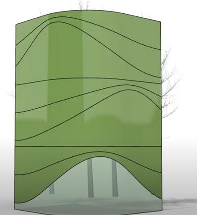
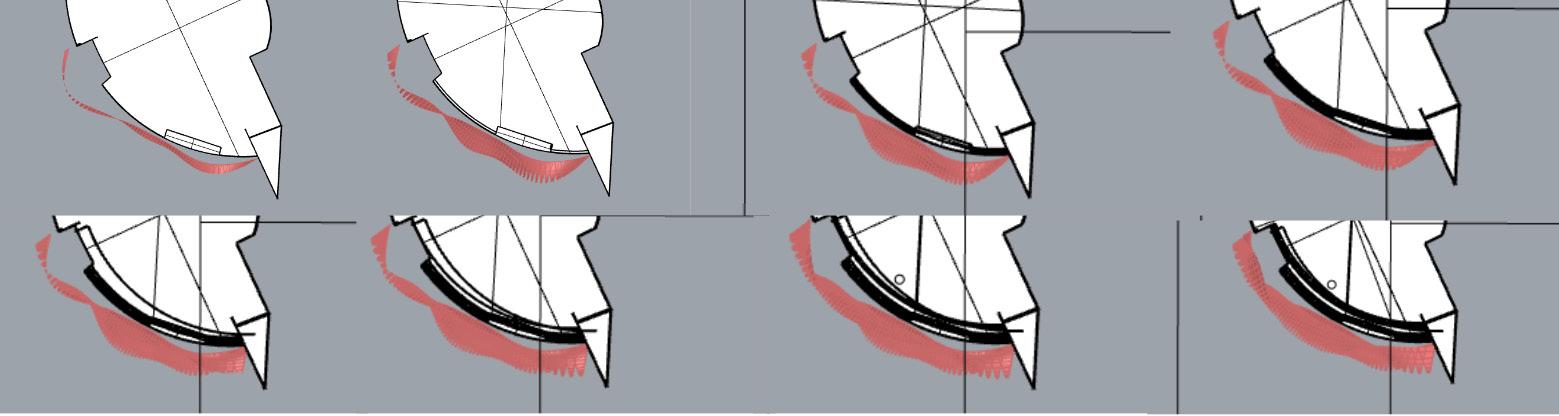
The height of curves can increase or decrease, allowing either more or less sunlight to enter the building. Curve can change directions towards needed wind (like in the first row) or change direction away from sun during summer (like in the second row) or change direction towards sun during winter (like in the third row).
Chapter name Portfolio 64
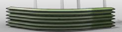
Single Panel Original Design
The wavelength of curve can also decrease or increase depending on environmental surrounding if too much heat is sensed from outside during summer, wavelength can decrease to block heat gain if too much cold is sensed from outside during winter, wavelength can increase to allow in more heat that can be preserved.
Responsive System Inspiration 1
I was inspired by both inspirations and started creating this sketch in which the curve closes when the sun hits and opens during wind entering.

Student Name ARCH 473/3522 - Spring 2019 65
Forming a Double Skin FacadeStatic or Responsive Design
Project 2.2: Parametric Design Strategy and Modeling
06
Stage 2 Derived Parameters, Rules, Relationships from Previous Experimentation
If too much heat is sensed from outside during summer, wavelength can decrease to block heat gain.
If too much cold is sensed from outside during winter, wavelength can increase to allow in more heat that can be preserved.
Chapter name Portfolio 68
Specified Point Specified Width Specified Length Create a Plane Changing Number of Points Vertically & Horizontally Number of Points in X Direction Number of Points in Y Direction Divide Surfaces into Points Create Parameter Alteration: Width & Length of Surface Parameters Alteration: Curve Wavelength Parameters Alteration: Height of Curves Parameters Alteration: Distance Between Each Curve Parameters Number Environmental Effect: Closing/Opening Curve for Less or More Heat
Parameters Alteration: Number of Strips Parameters Number
Parameters Alteration: Number of Folded Curves at Given Point
Environmental Effect: More/Less Shade
Environmental Effect: Allowing/Blocking of Wind
The curve can change directions towards needed wind or change direction away from sun during summer or change direction towards sun during winter.
Student Name ARCH 473/3522 - Spring 2019 69 Domain Start (Minimum) Domain Start (Maximum) Specified Depth of Curve Curve Angle
Points Construct Domain Parameters Alteration: Number of Concave Curves Parameters Alteration: Curve Extrusion (Depth) Parameters Alteration: Curve Rotation/Direction
Curves
by Altering
Wind from North & North West Curves will usually be opened here to allow for wind.
Extruded Curves During Hot Sun for Shade & Decreased Spacing During Hot Sun for Shade & Increased
Chapter name Portfolio 70 Material Exploration Learning from Materiality
Increased Spacing to Allow Cool Air to Enter
Stage 2 Specific Strategy Adopted for Parametric & Generative Exploration Exercise

Spatial Design from Inside
Student Name ARCH
Spring 2019 71 Fall 2022
Fall
473/3522 -
ARCH 473/3522 -
2022
Precedents
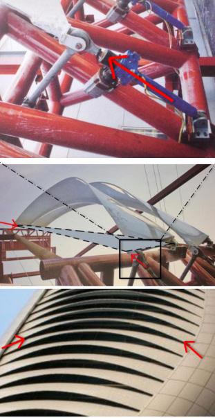
Stage 2 Achieving Variation & Complexity Via Selected Strategies
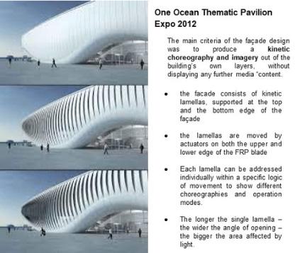
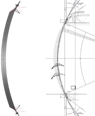
This double skin facade has 108 kinetic louvers supported at top and bottom edge of façad. The lamellae is glass fiber reinforced polymers (GFRP) (high tensile strength with low bending stiffness, creating large reversible elastic deformations. The louvers are moved by actuators on both upper & lower edge of GFRP blade which induce compression forces to create complex elastic deformation. (This is what I was inspired by in my design as I’ve did a simplified version of this structure though simple pipes on Grasshopper). They also reduce the distance between two bearings which then induce bending.
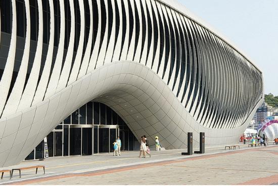
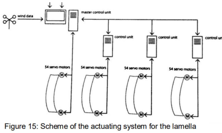
The actuator of the louvers are the screw spindle driven by a servomotor and there’s a computer controlled bus-system that allows the synchronization of actuators. Each lamella addressed individually within specific logic of movement shows different choreographies & operation modes. The technical concept consists of elastic deformation, adaptive pre-stress, and energy retrieval. The master control unit is navigated by the computer getting information related to wind data, choreography & interior lightning requirements (Schinegger et al., 2012).
Chapter name Portfolio 72 Material Exploration
One Ocean, Yeosu
Learning from Materiality Portfolio
(Schinegger et al., 2012)
(Schinegger et al., 2012)
Student Name ARCH 473/3522 - Spring 2019 73 Fall 2022 ARCH 473/3522 - Fall 2022
(Schinegger et al., 2012)
(Schinegger et al., 2012)
(Schinegger et al., 2012)
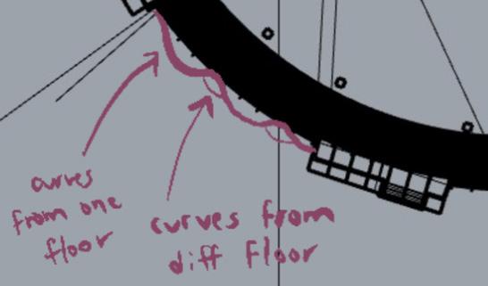
Stage 2 First Attempt in Grasshopper to Devise Logic of Facade
Parameters Experimented: Coordinates of Each Curve
Parameters Experimented: Boundaries of Curves
Parameters Experimented: Number of Rows (Floors)
Parameters Experimented: Number of Rows (Floors) & Columns


Chapter name Portfolio 74 Learning from Materiality
Experimented: (Floors) & Columns
I have to go back to my old code and see what commands I used to create the descending spacing between the stripes to follow my original concept of “setting free” gradually through having the spaces increase gradually.
Parameters Experimented: Number of Vertical and Horizontal Divisions
Reflection:
Parameters Experimented: Cull Patterns (Space Between Each Strip as a Pattern Instead of Value or Range of Ascending/Descending Values
It felt like I was restricted at first to edit the slabs or heights of the building, however it turned out that we can change them based on our own facade design and thus in the next stage I was able to have my mind more open to that instead of having stacked rooms. So far I wanted my operational mechanism of the façade to be responsive yet I’m still experimenting with how that can be possible with my code and design. I still have the structure (actuators) kept in my mind as I want to also my facade attached from its top and bottom with a similar kind of structure.
Student Name
473/3522 - Spring 2019 75 Fall 2022
ARCH
ARCH 473/3522 - Fall 2022
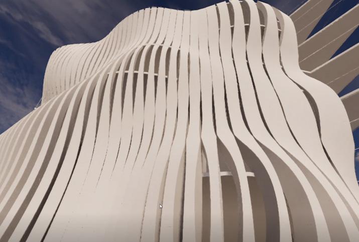
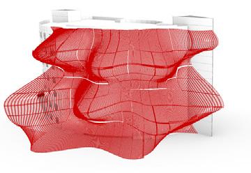
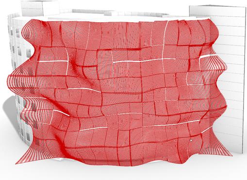
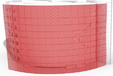
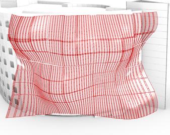
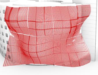
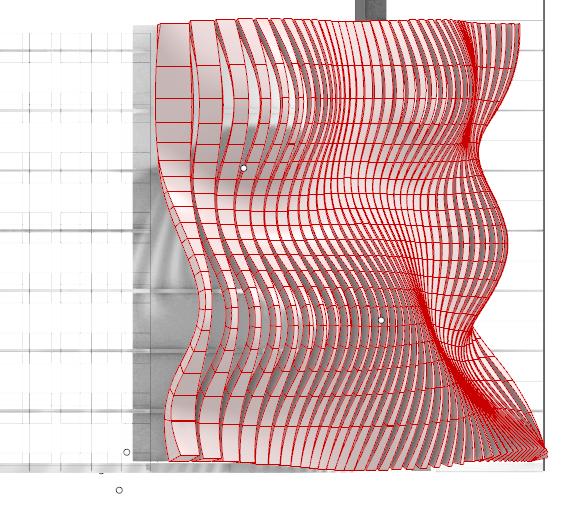
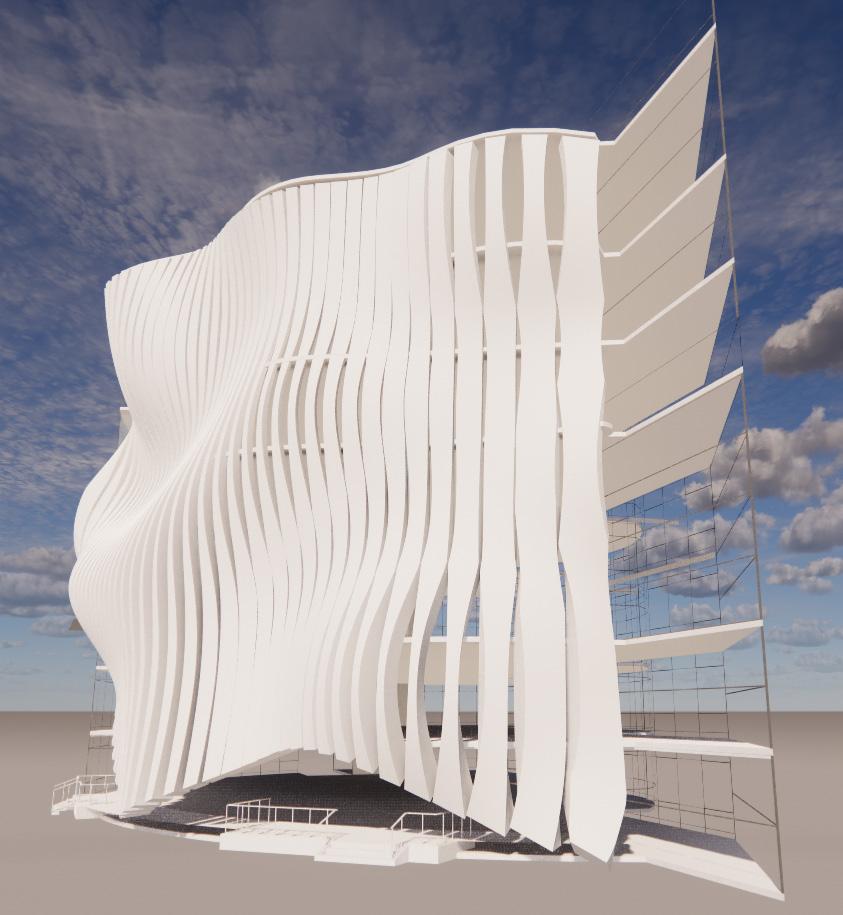
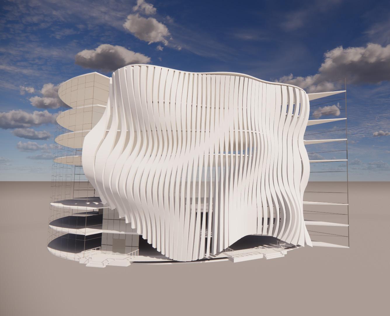
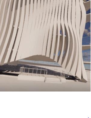
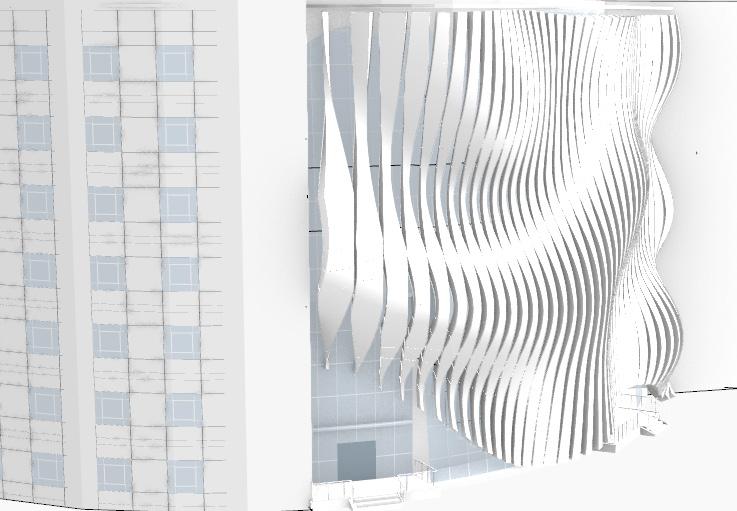
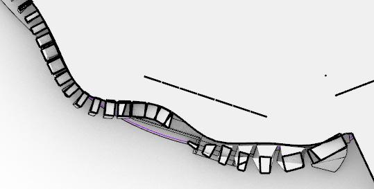
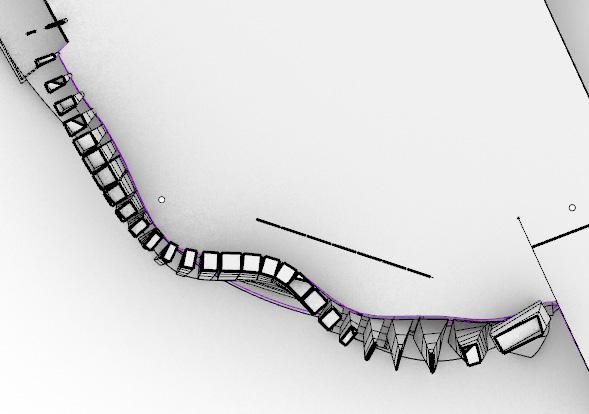
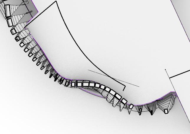
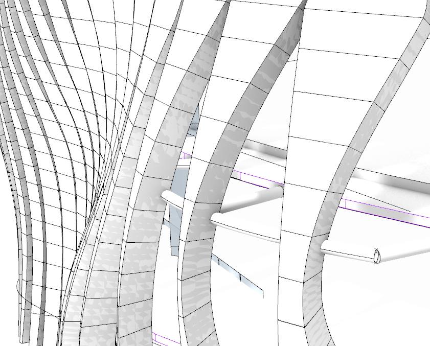
Double Skin Facade in Progress
At a Different Angle
Project 1.3: Parametric Modelling
07
Precedents
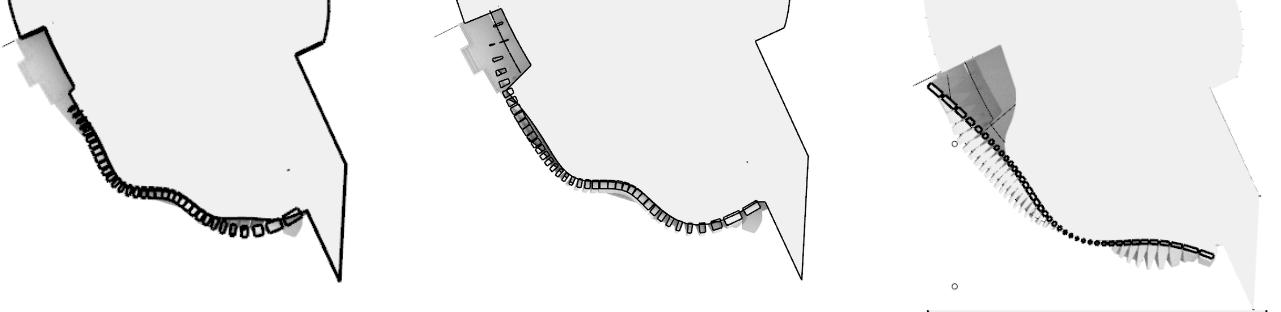
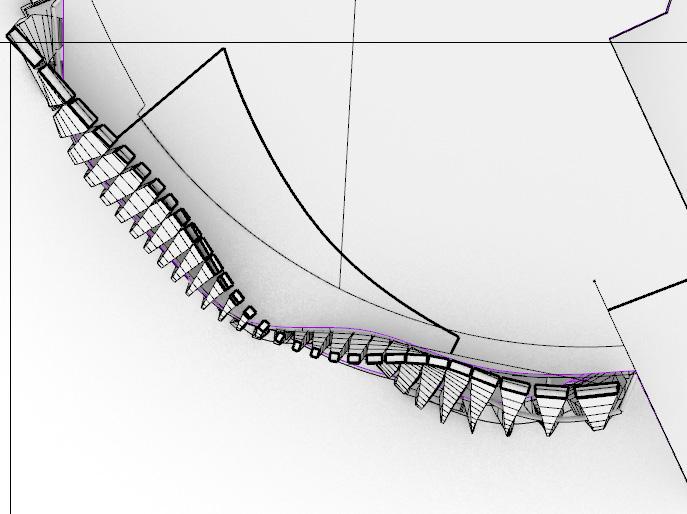
Stage 3 Spatial Concept in Progress & Grasshopper
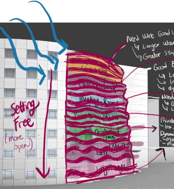
We were required to demonstrate our attempts in Grasshopper to represent the full logic of the building façade skin and how we utilize our parametric strategy to propagate the initial design module/unit throughout the whole building façade. We are required to map this on the Rhino model of the existing building, which should also comprise our spatial/interior modifications to illustrate our overall intervention.
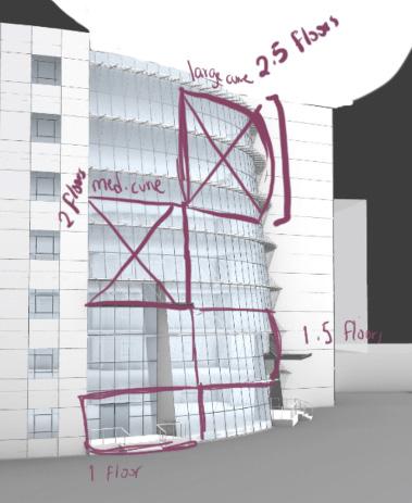
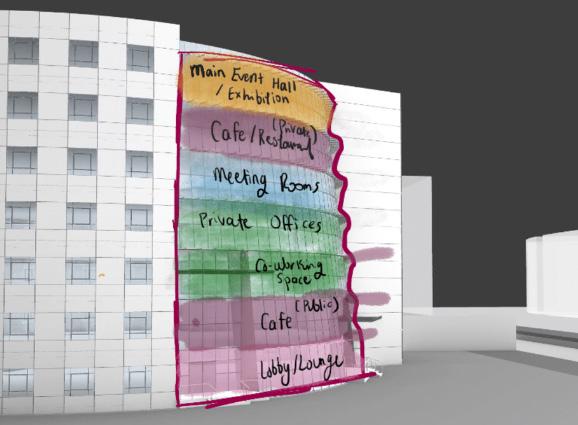
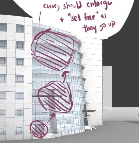
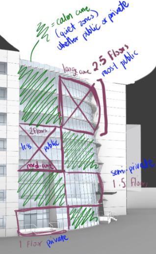
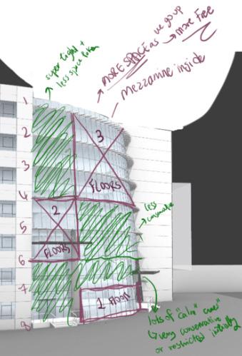
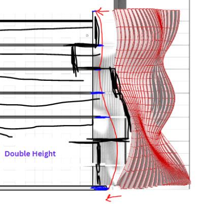
As shown in the diagrams, I re-designed the height of my spaces depending on their function, their privacy and what kind of noise level the user inside would prefer which would affect my decision of making them at a higher or lower floow level. I tried to relate this to my initial concept of “setting free” by making the floors become more double height as they go up. I focused mainly more on the spaces’ neeeds in these sketches more than the environmental connections.
Chapter name Portfolio 78 Material Exploration
Learning from Materiality
Student Name ARCH 473/3522 - Spring 2019 79 Fall 2022 Fall 2022 ARCH 473/3522 - Fall 2022
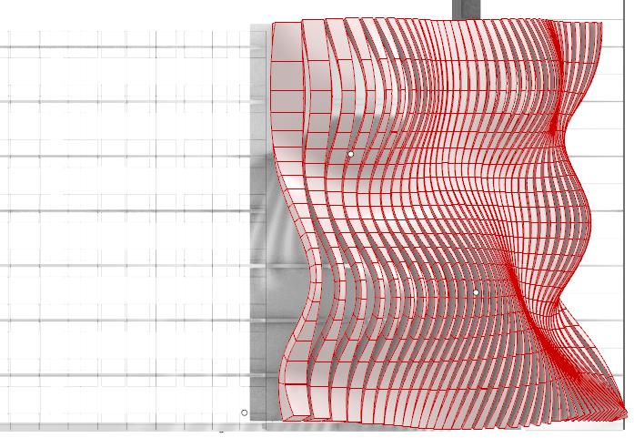
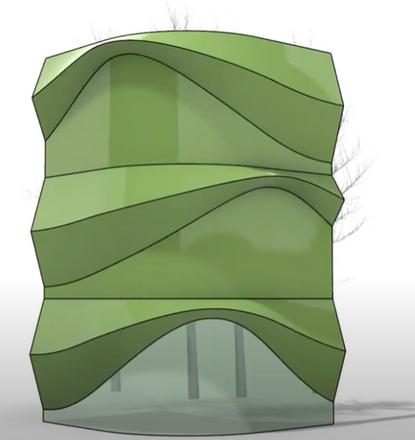
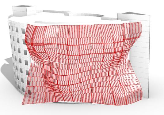
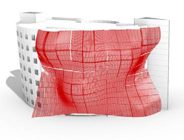
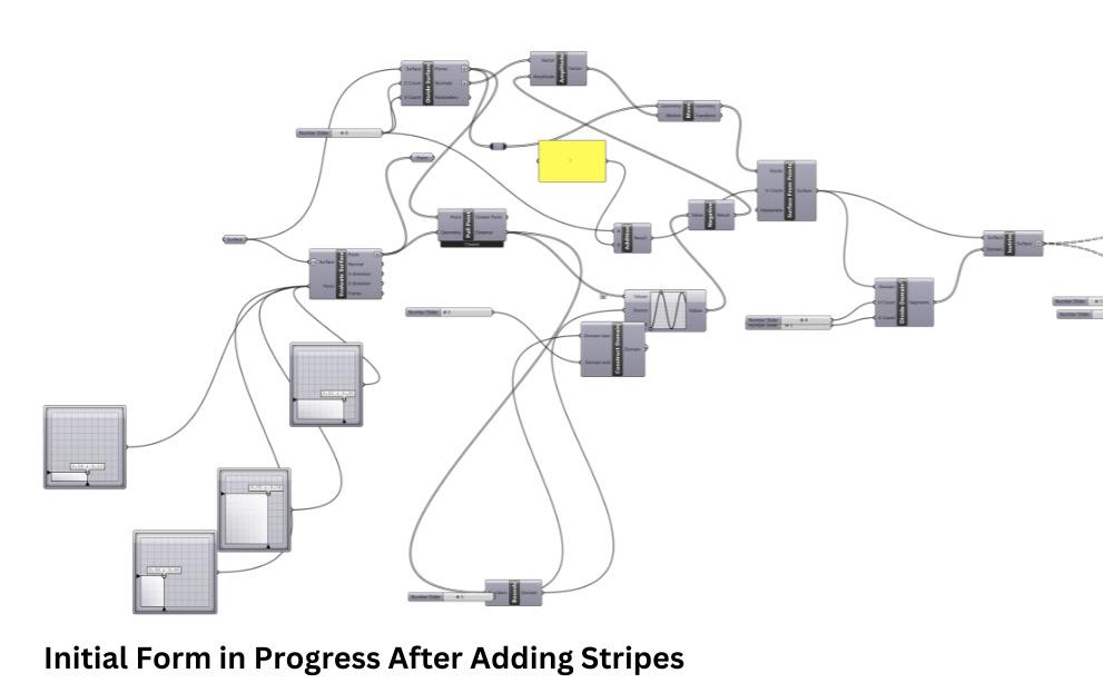
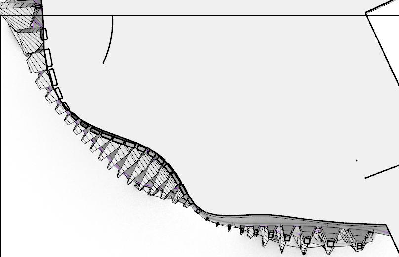
Stage 2 Initial Form in Progress After Adding Stripess
For Further Improvement:
Increasing Strips in West (sun angles are low) Increasing Between Strips Environmental Effect: Vertical Shading; allowing light, views, ventilation (while excluding sun)
Chapter name Portfolio 80
Improvement: Spacing Strips in West
Decreasing Spacing Between Strips in South
Environmental Effect:
Shading (blocking of sun) due to high sun angle
Student Name ARCH 473/3522 - Spring 2019 81
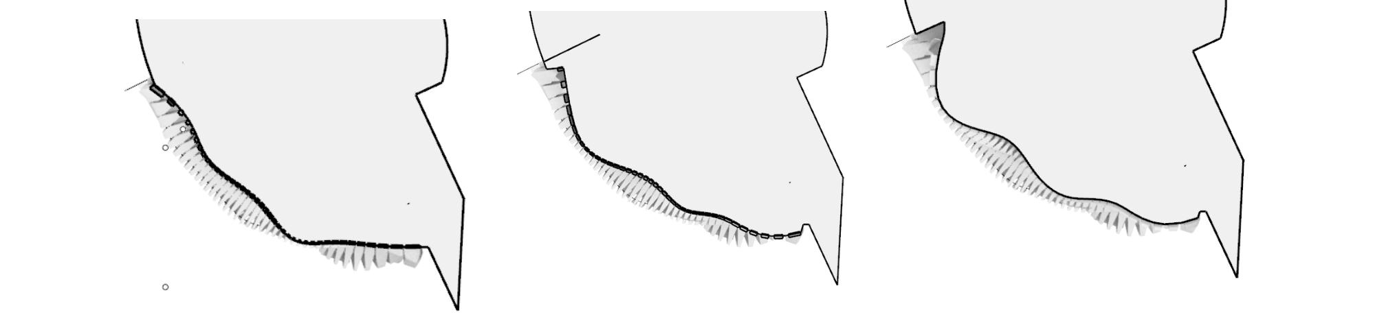
Altering Domain Maximum of Remap
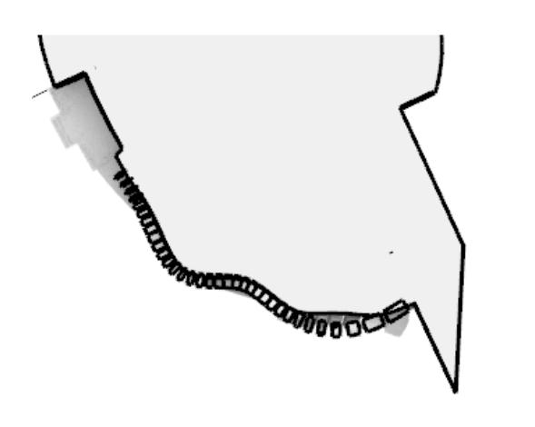
Stage 3 Initial Form in Progress After Adding Stripess
Parameter 1
Domain of Application
Changing Spacing Between Stripes
Altering Domain Minimum of Remap
Learning from Materiality Portfolio
Changed Curve Locations to Reach Closest Current Outcome of More Vertical Louvers to West & Less Stripes to South

Plans
ARCH 473/3522 - Fall 2022
Domain of Application Stage 3 Continuation of Building Facade
Progress of Spatial Configurations, Sections, Plans
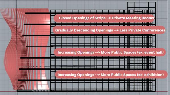
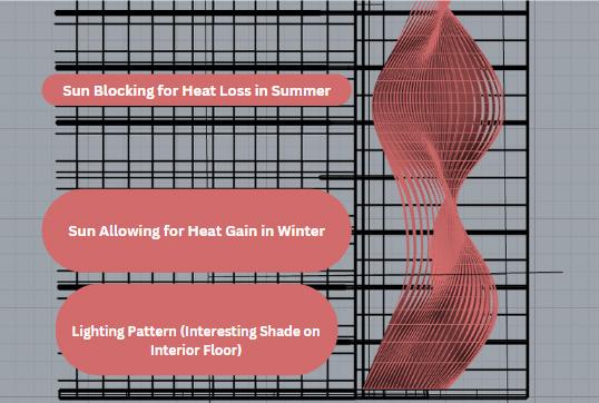
I was stuck in the phase of spatial configurations and it’s relationship with the environmental factors or at least one chosen main factor. I extracted sections from the South and the West to start beginning to see the effect of the facade shape on the inside to create further connections.
Suggestion to Self: shift surface to left to make curves attached to slabs with structure.
Precedents Learning from Materiality
Chapter name Portfolio 84
Closed Openings of Strips --> Private Meeting Rooms
Gradually Descending Openings --> Less Private Conferences Increasing Openings --> More Public Spaces (ex: event hall) Increasing Openings --> More Public Spaces (ex: exhibition)
Sun Blocking for Heat Loss in Summer
Sun Allowing for Heat Gain in Winter
Lighting Pattern (Interesting Shade on Interior Floor)
Reflection:
I did not know how to improve on my facade or how to diversify the slabs or even the actual complexity of the facade itself as I was thinking that it’s too simple with not even parameters to play with. Thus I attempted to think of more ideas such as”squinching” some strips to create one large opening between stripes when needed for extra daylight or heat. However, it wasn’t the greatest idea as it would’ve unnecessarily made the facade more complex for the sake of creating complexity rather than an actual justifcation.
Student Name ARCH 473/3522 - Spring 2019 85
ARCH 473/3522 - Fall 2022
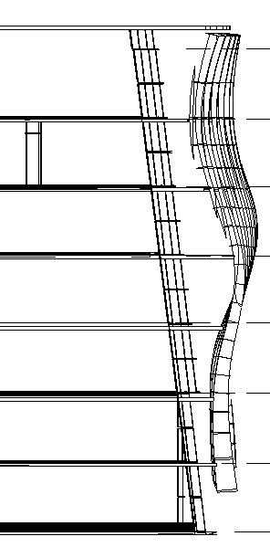
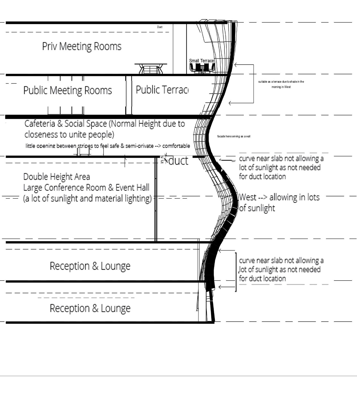
West Section in Progress
Priv Meeting Rooms

Stage 3 Continuation of Building Facade
Section & Plans in Progress
Public Meeting Rooms Public Terrace
Cafeteria & Social Space (Normal Height due to closeness to unite people)
little opening between stripes to feel safe & semi-private --> comfortable
Precedents ` Technique
Double Height Area
Large Conference Room & Event Hall (a lot of sunlight and material lighting)
Reception & Lounge
curve near slab not allowing a lot of sunlight as not needed for duct location
West --> allowing in lots of sunlight
curve near slab not allowing a lot of sunlight as not needed for duct location
Reception & Lounge
I started importing my facade from Rhino to Revit as a mass so that I can start creating my slabs directly from Revit then exporting it back to Rhino as I was more flexible with this since I can easily select the outline of the facade where it touches the slab to help me in creating the exterior of the slab. However, I was still confused on how to make the plans look more diverse and have more variety. The west section included more annotations than the south section as I had already spent too much time working on one section (it was hard to extract ideas and connections at this phase).
Chapter name Portfolio 88
Level 1 0.0 Level 2 3.1 Level 5 12.3 Level 6 15.4 Level 7 18.4 Level 8 21.5 Duct Duct curve near slab not allowing a lot of sunlight as not needed for duct location curve near slab not allowing a lot of sunlight as not needed for duct location 0.5 West > allowing in lots of sunlight suitable as a terrace due to shade in the morning in West Large Terrace Small Terrace Private Meeting Rooms Public Meeting Rooms facade here serving as a wall Cafeteria & Social Space (Normal Height due to closeness to unite people) little opening between stripes to feel safe & semi-private > comfortable Reception & Lounge Reception & Lounge Section Learning from Materiality
Domain
duct
South Section in Progress Reflection:
I creates openings for the entrances and started using importing the facade from Rhino as a mass to Revit, drew the outline of the facade in interior to either fit exactly the slab like a puzzle completing one another & have the facade be served as a wall, or have a curtain wall that’s offsetted from the facade, allowing for space to create terraces wherever suitable.

Student Name ARCH 473/3522 - Spring 2019 89
ARCH 473/3522 - Fall 2022 of
Application

Student Name ARCH 473/3522 - Spring 2019 Technique Fall 2022 ARCH 473/3522 - Fall 2022
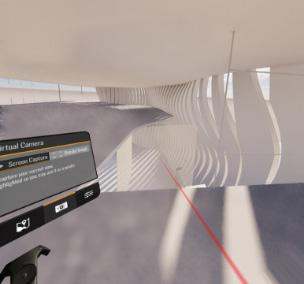
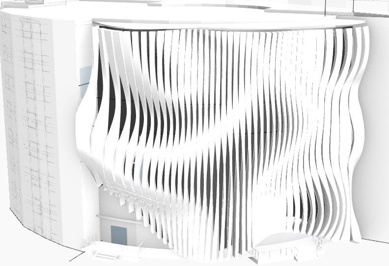
Entering the VR Lab with This View 08
Project 2.4: Final Stage
93
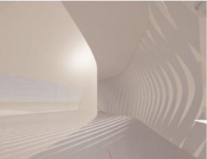
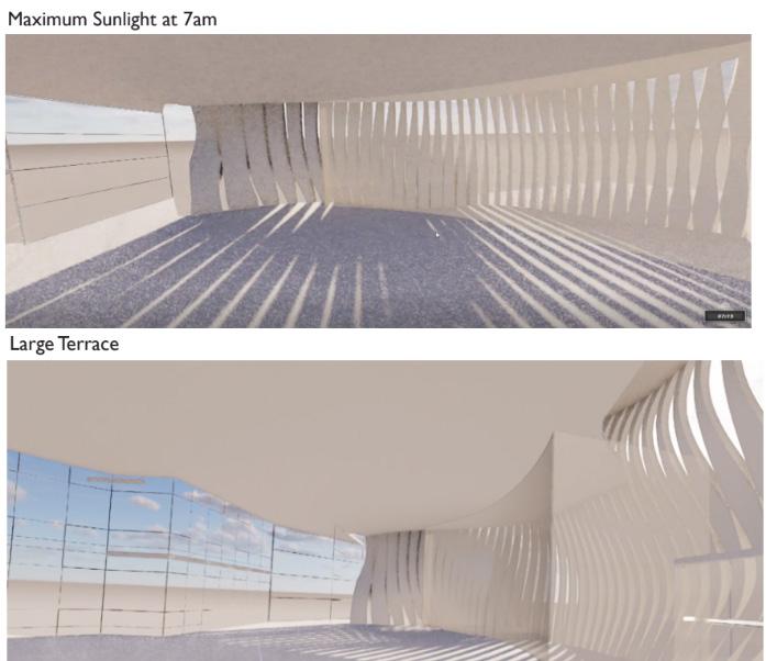
Stage 4 VR Shots
Double Height Attempt Small Terrace
Slab Needs Structure With Facade
Reflection: The openings of the facade were too little and thus didn’t show enough variety, therefore it needed greater opening or at least the pattern of having descending voids between the strips at each concave curve can be more emphasized. The structure also needed to be added even though I’ve already made the code for it. I also needed to create a more interesting interior experience. The previous section I’ve done in the West also doesn’t seem to be applied during the VR shots, as it showed a way moroe simplified version of it that needs to be worked on.
Chapter name Portfolio 94
Learning from Materiality Portfolio
“Before”
The curtain walls are not touching the roof (slab above) and the rectilinear language isn’t fitting with the curvilinear facade.
ARCH 473/3522 - Fall 2022
ARCH 473/3522 - Spring 2019
Student Name
95
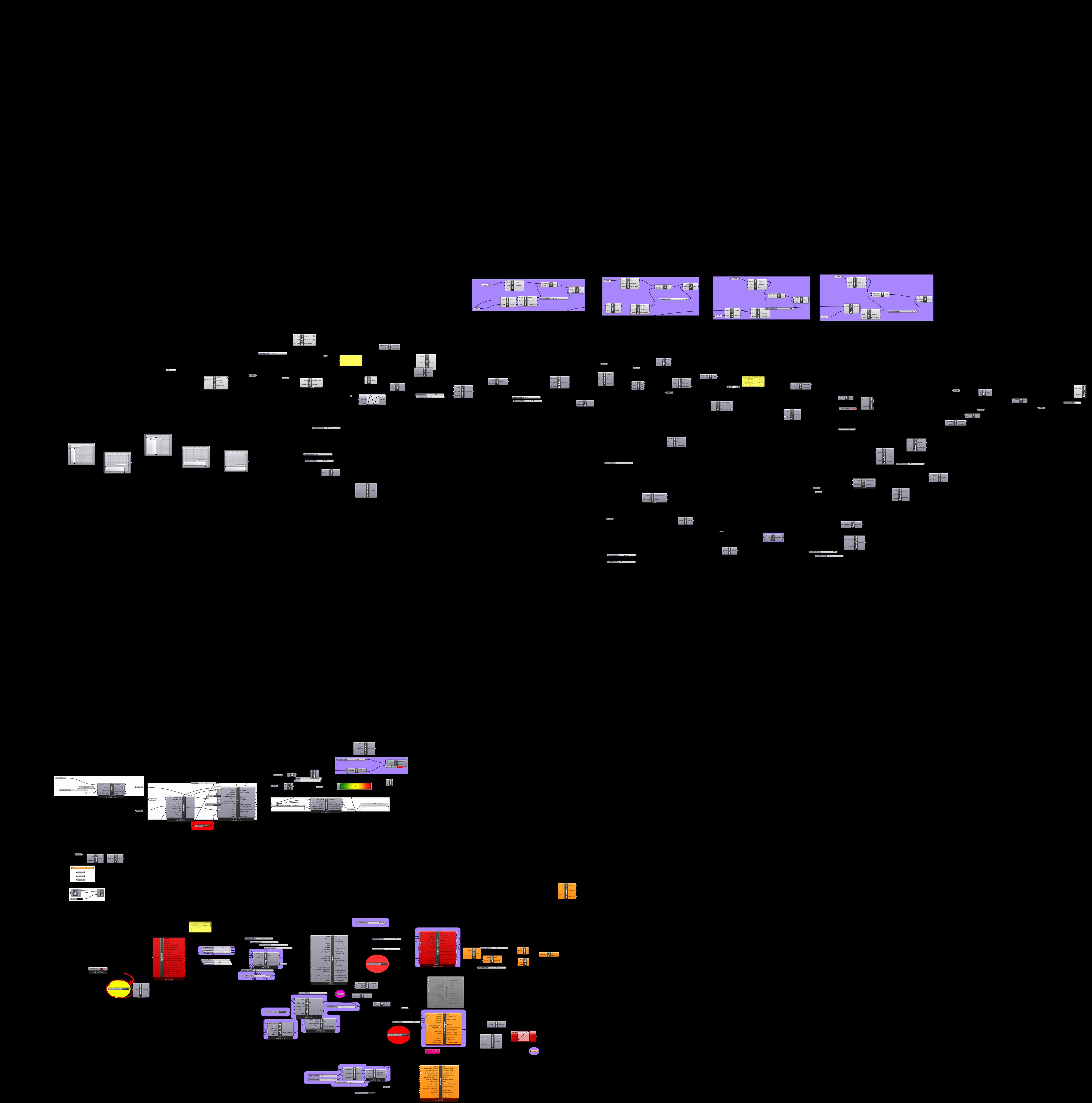
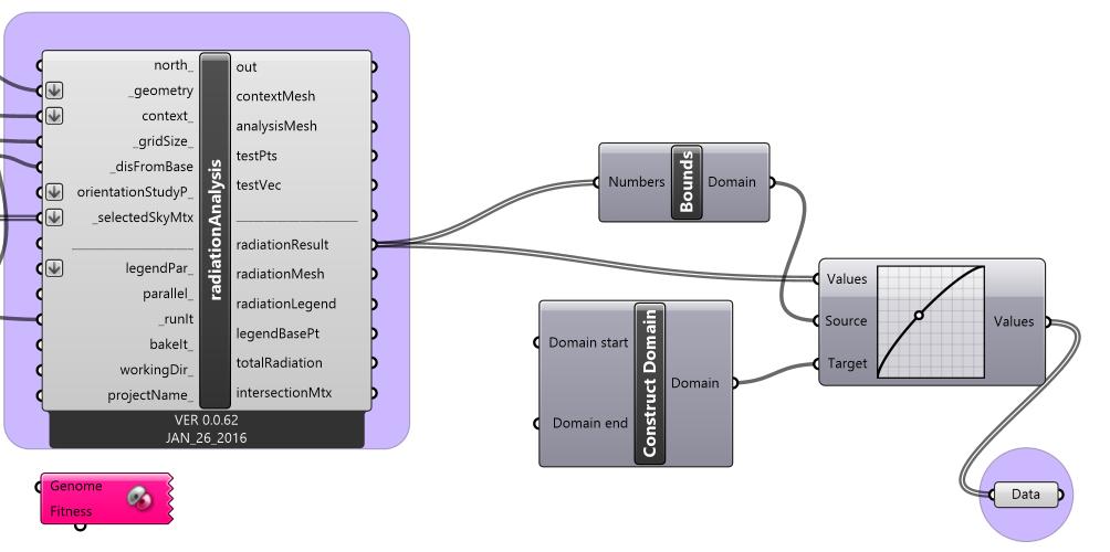
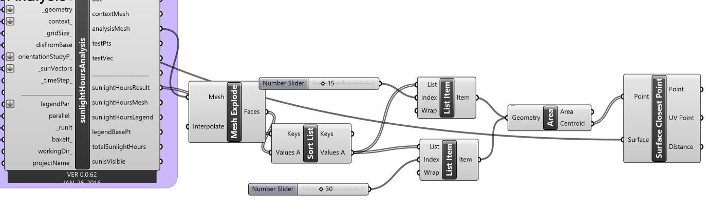
Stage 4 Grasshopper Code for Environmental Analysis)
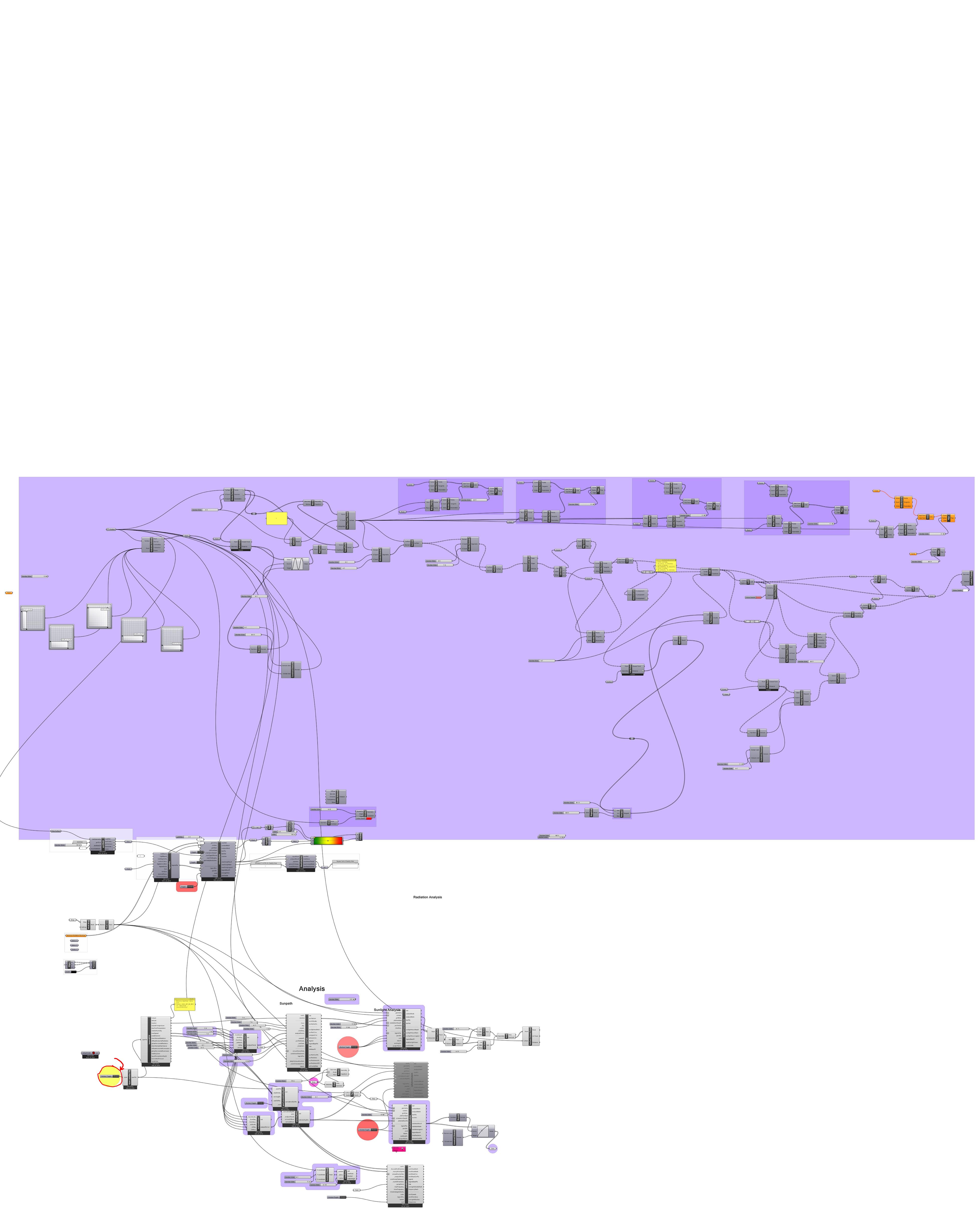
Chapter name Portfolio 96
Student Name ARCH 473/3522 - Spring 2019
Original Design
Original design had openings well suited for such indirect lighting here.
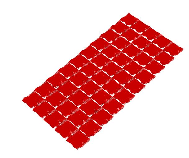
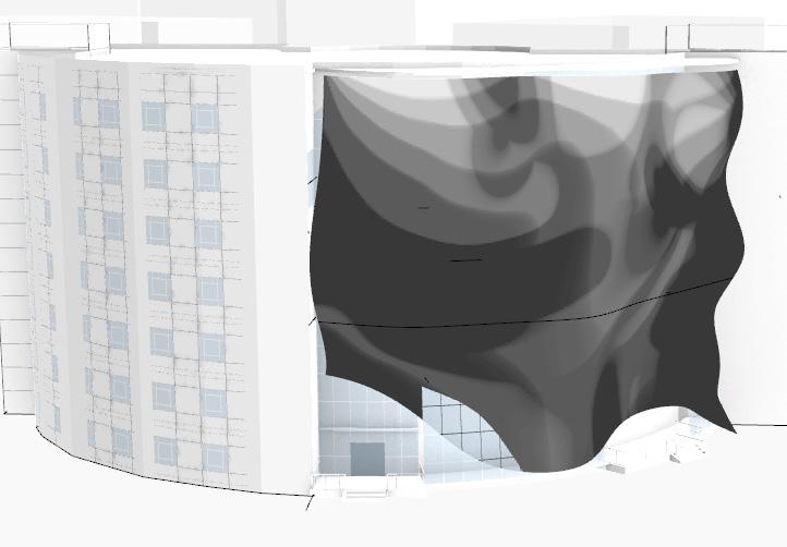
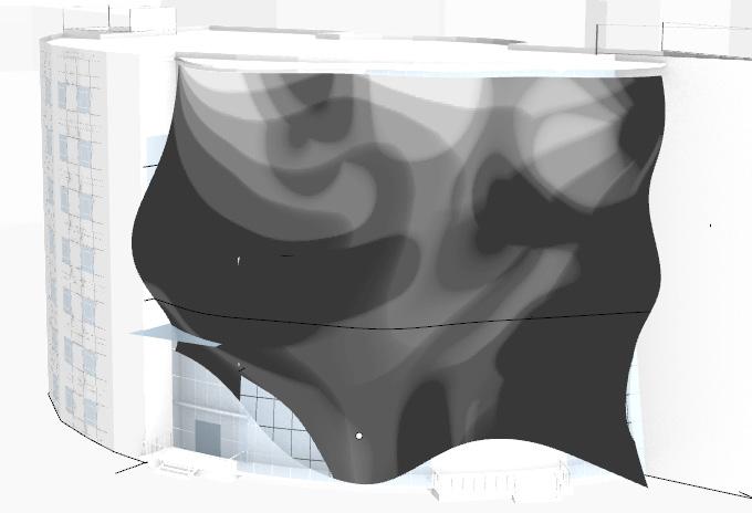
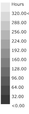
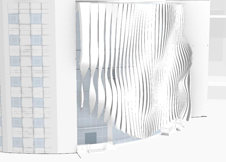
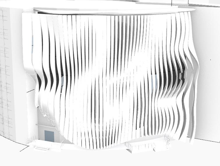
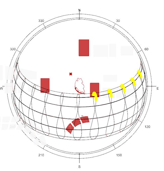
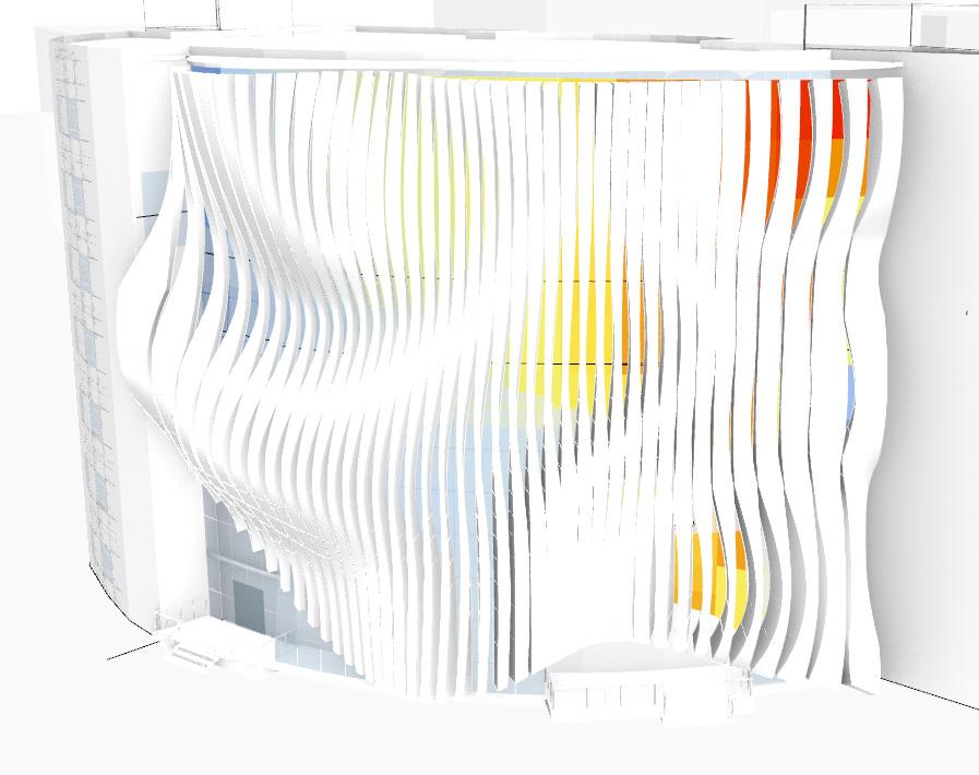
Sunlight Analysis
Stage 4 Environmental Analayses
There is little solid area with few openings.
Precedents
Using grasshopper, the number of hours of direct sunlight received by the facade using sun vectors from the sunPath component was studied. Black represents least amount of direct sunlight and white represents the most.
Chapter name Portfolio 98 Learning from Materiality
Precedents
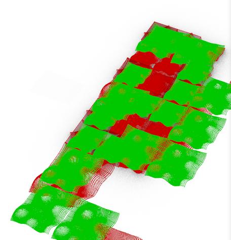
Automated Adjusted Design Based on Simulation (Increase in Openings at Lowest Radiation (Black) for More Indirect Sunlight
Automated design based on simulation made the facade more protruded inside which provided the same aspect as old design yet wasn’t as aesthetically pleasing.
More wider openings created based on simulation to allow for more indirect sunlight (as this area was black).
Student Name ARCH 473/3522 - Spring 2019 99 ARCH 473/3522 - Fall 2022
Changing Design Manually Stage 4 Environmental Analayses
I struggled to make the curves in my facade more customized on Grasshopper as I attempted to do a design that’s extracted automatically through Grasshopper based on the simulation of solar radiation, yet it didn’t effectively work on my facade.
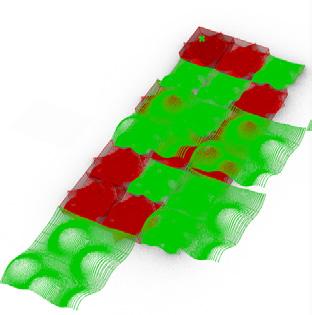
Reflection:
This was another attempt to have the darkest areas from the Radiation analysis extracted as data and be used to allow for openings of my strips to increase at these areas, however although it worked, the design created could be further improved aesthetically and to fit the spatial requirements.
Chapter name Portfolio 100
Wind Rose Sunlight Path
Student Name ARCH 473/3522 - Spring 2019 101
473/3522 - Fall 2022
ARCH
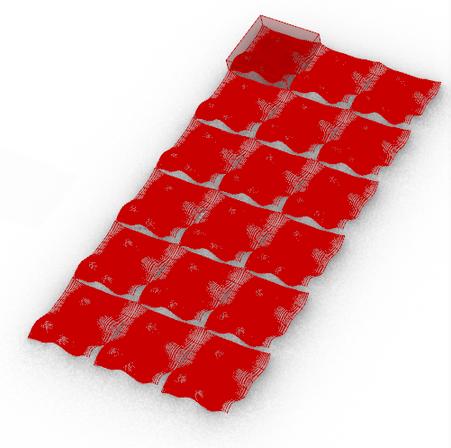
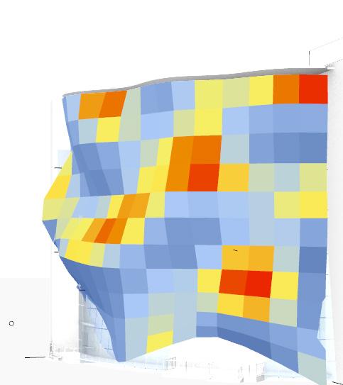
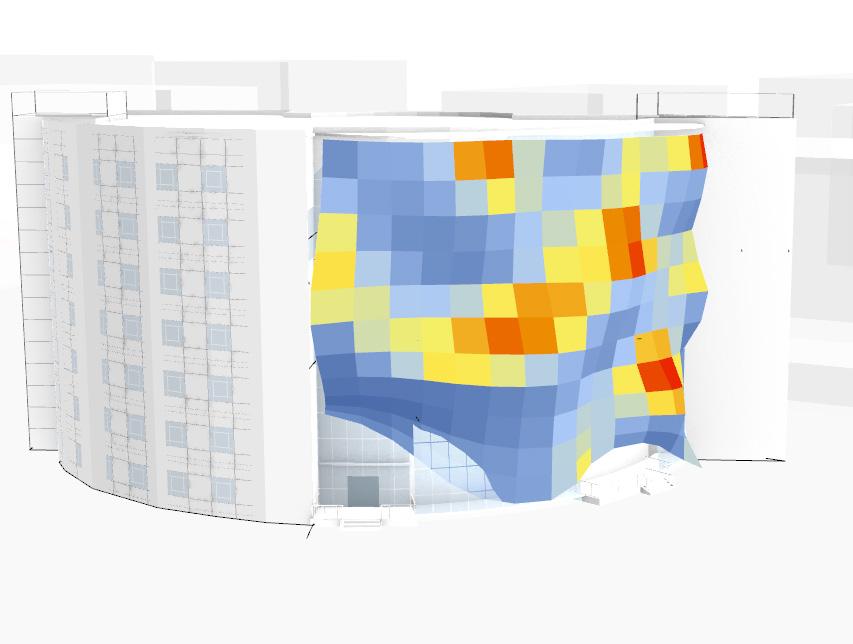
Radiation Analysis
Using Automated Adjusted Design & Original Radiation Analysis to Create Own Design Decisions
I increased the size of the openings to allow in more heat and lighting as they weren’t as visible before.
Reflection:
A suggestion is to perform this analysis also on the slabs to see how the sun is affecting the users from within the interior space itself (having the double skin facade the context in this case and the slabs as the geometry input).
Chapter name Portfolio 102
Learning from Materiality
I’ve played with the graphs that change the coordinates of the curves in order to have more closed openings where it’s more radiated (white) to prevent excess heat gain in building during Summer (June-August) and have more openings in the black areas.
Student Name ARCH 473/3522 - Spring 2019 103 ARCH 473/3522 - Fall 2022
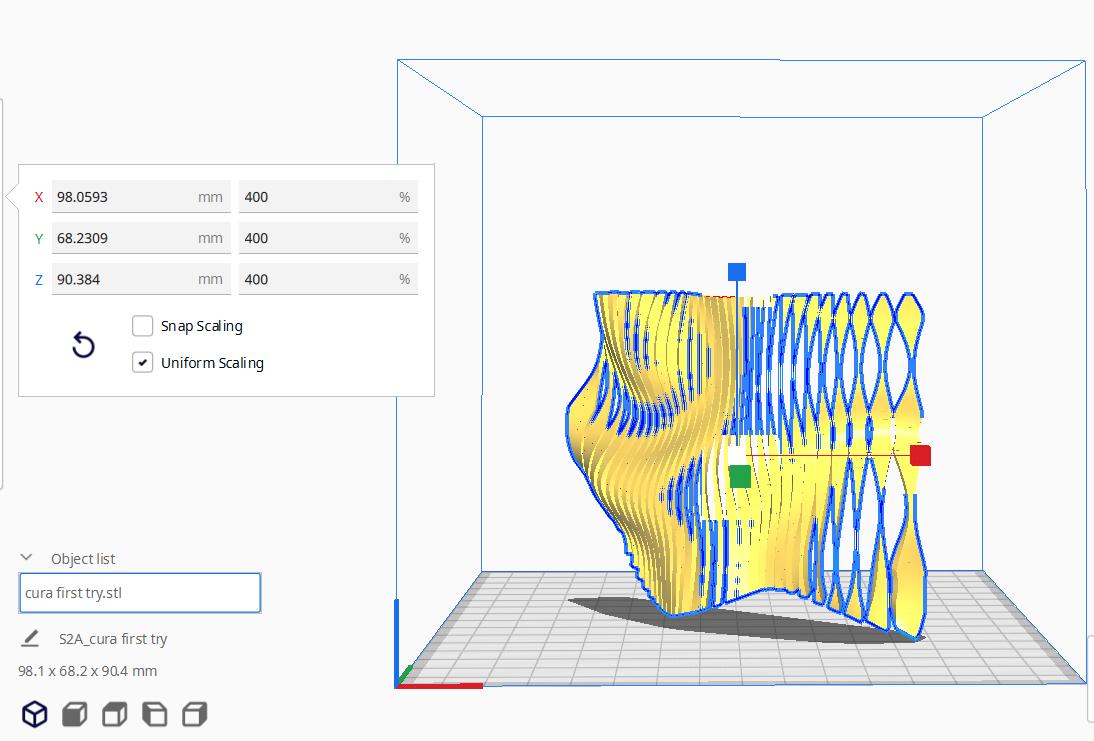
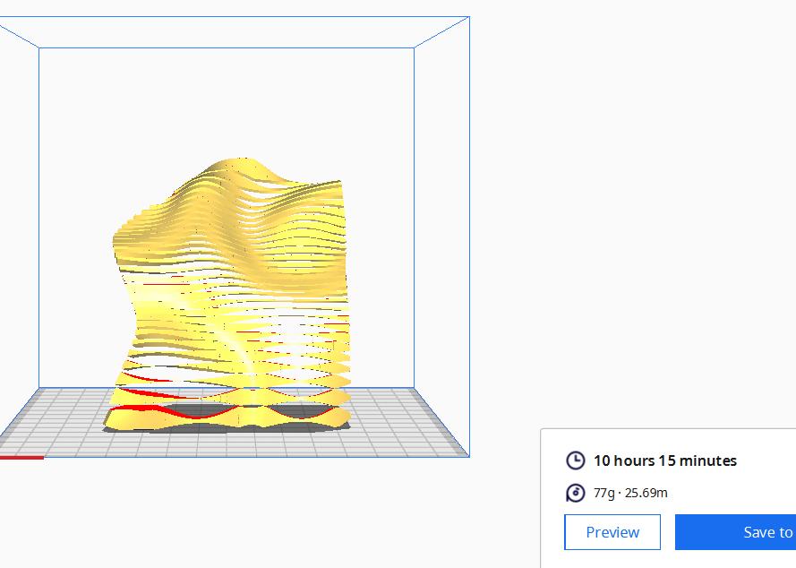
Stage 4 Fabrication
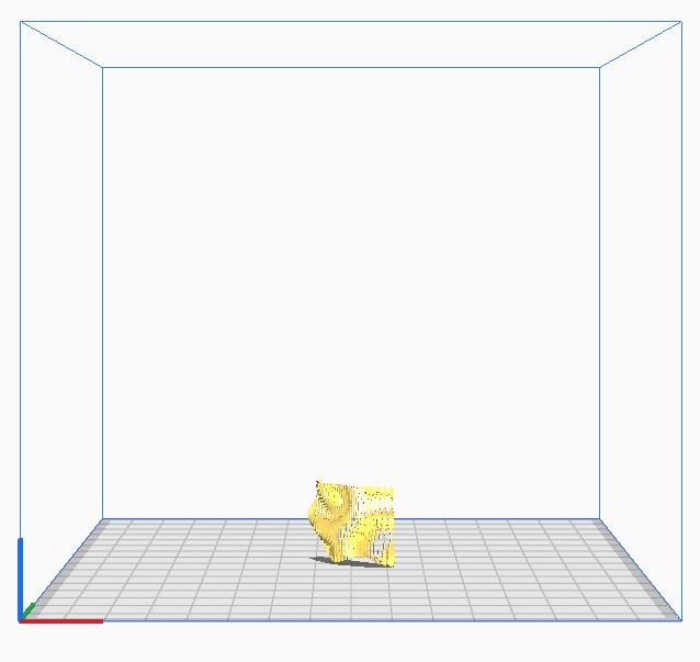
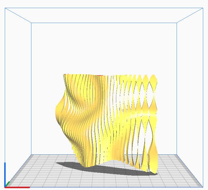
I started the fabrication process by exporting the facade from Rhino as an “.stl” file and importing it in Ultimaker Cura. The facade was automatically imported in millimeters. as default (Fig. 1), even though the units in Rhino is in meters. When I sliced it, the process was listed as 9 minutes as the duration for the facade to 3D print, which was what made me realize that there is an issue with the size. Therefore, I enlarged the scale of the facade to 400% (Fig. 2) to create a reasonable, logical size for the final real life product (Fig. 3). The adjusted total time process was then 5 hours and 10 minutes. With that reason, I started rotating the facade to investigate how it can affect the time process.


Chapter name Portfolio 104
Fig. 1 Facade in Default Size (Millimeters)
Fig. 3 Facade After Enlargement
Learning from Materiality
Fig. 2 Enlarging Facade to Reasonable Printing Size
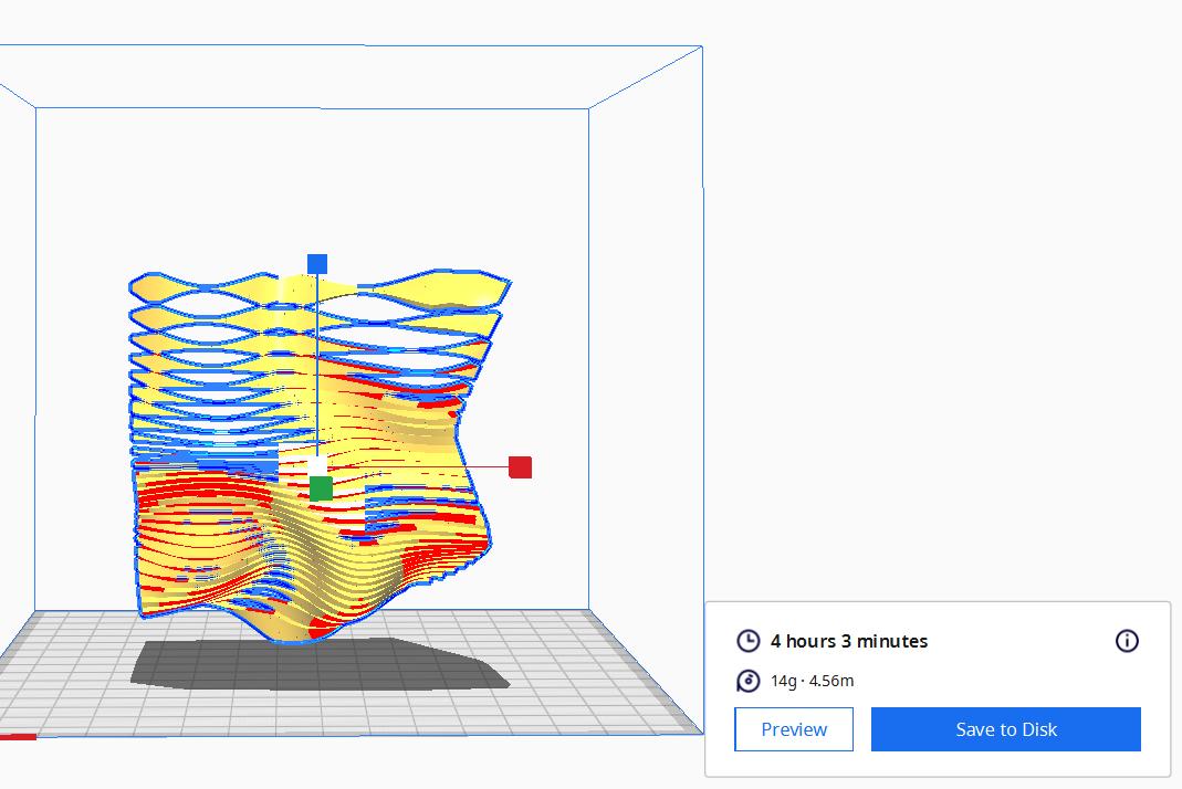
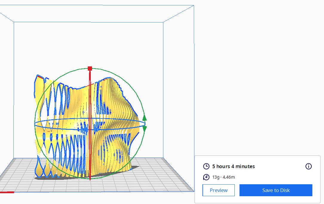
I kept rotating my model to see in which rotation will my facade print in the shortest time and the shortest time was 4 hours and 3 minutes.
Student Name ARCH 473/3522 - Spring 2019 105 ARCH 473/3522 - Fall 2022
West Section
Stage 4 Plans, Sections, Form
suitable as terrace due to shade in morning in West
Chapter name Portfolio 106
Student Name ARCH 473/3522 - Spring 2019 107 Fall 2022 ARCH 473/3522 - Fall 2022
I struggled in extracting sections and plans as I was iinitially working on Revit and built walls and curtain walls in the interior spaces, however the black cut would never show even though I’ve always worked with importing masses and making them show the black section cut. So, I’ve just used the Clipping Plane command on Rhino to extract my plans even though they’re plain and although I’ve had already added funiture on my Revit plans. I’m not that satisfied with the outcome of the plans and sections as even the structure I spent working on didn’t show in these drawings.
Chapter name Portfolio 108
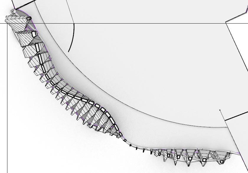
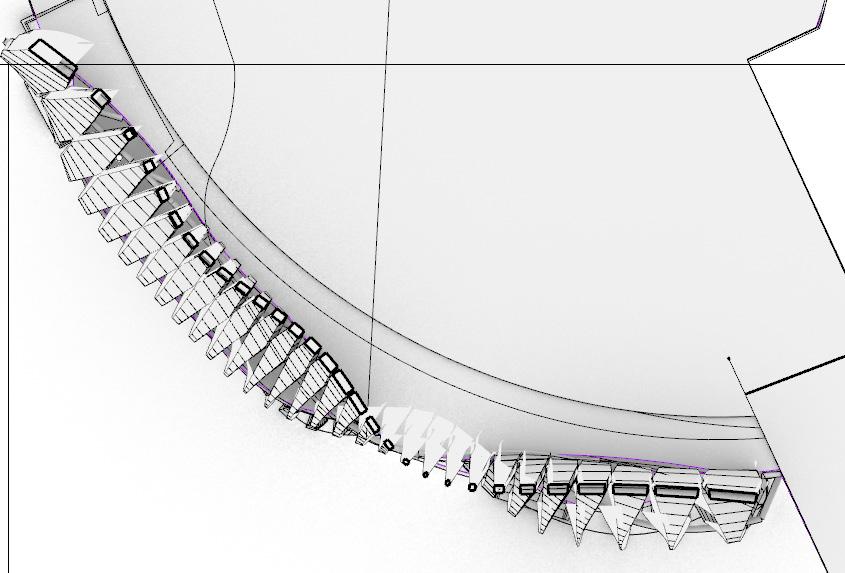
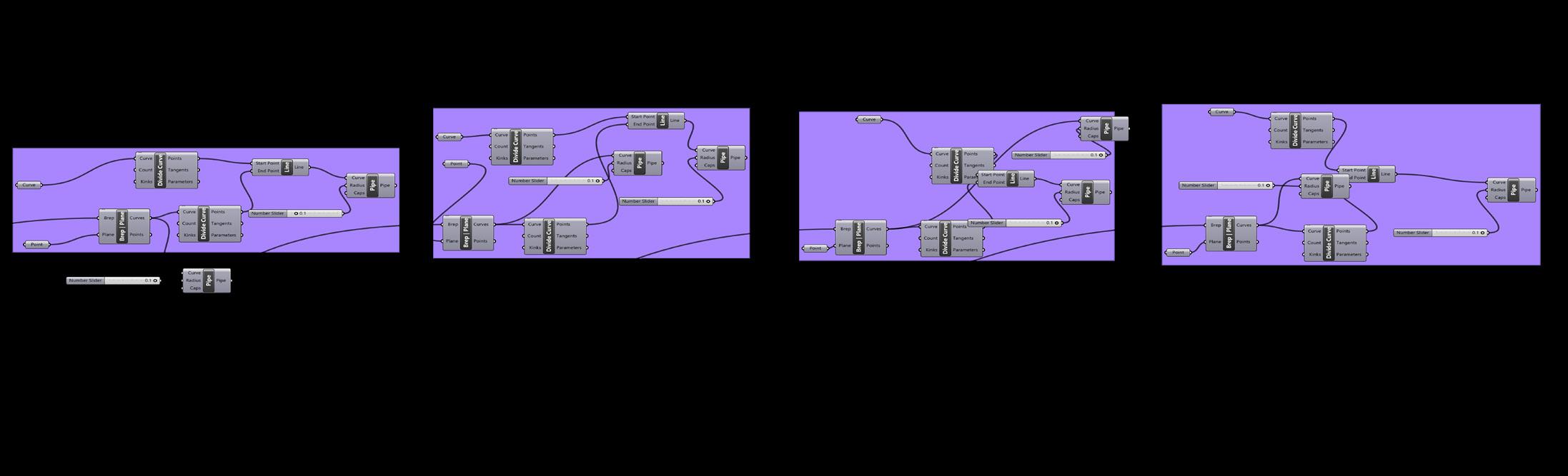
Grasshopper Code for Making the Structure Connection Between Slab and Facade
Overall Course Reflection:
I really loved and enjoyed this course to be honest and it helped me create my main structure in my Vertical A project. I’ve even used the same similar structure that represents a “rib” kind of structure in the previous code shown above like the one I used also in my Vertical A project so I cam up with that code on my own based on my experience already which was surprising to me personally as I would always feel the need to ask a TA for help in Grasshopper. Although I feel like I’ve done relatively good progress in Project 1, I could have done way better in Project 2, yet I spent stuck in a long time trying to figure out whether my facade should be static or responsive (which turned out to be static). I could have also spent more time explaining which parts of the facade respect to which environmental parameter like the temperature and wind which is there but didn’t deeply explain it. The wide openings let in indirect sunlight and cool wind while the closed openings block high heat. Overall, I really loved this course and I’m super grateful I had this opportunity to take it.
Student Name ARCH 473/3522 - Spring 2019 109
Biblography
• https://www.semanticscholar.org/paper/Design-process-for-protot ype-concrete-shells-using-Veenendaal-Block/9ecb734bd541397e124e05208ca6ce84d783954a#paper-header
• https://www.holcimfoundation.org/projects/latex-formwork
• https://www.sciencedirect.com/science/article/abs/pii/S0141029614003344
• https://www.etsy.com/au/listing/398262649/metal-bird-mobile-4-piece-kinetic-art-in
• https://mymodernmet.com/modern-architecture-2/
• https://hbottlefield.com/universitas/chapter-3/sea-shell-buildings.html
• https://www.sciencedirect.com/topics/engineering/double-skin-facade
©All rights reserved, American University in Cairo (AUC) September 2022