PORTFOLIO
Building Simulation and Design in Context 19272488

Building Simulation and Design in Context 19272488
UK’s building stock is mainly tailored for the cold climate With increasing global temperatures and unpredictable climatic conditions, it is alarming that existing buildings and designs might cause overheating and unlivable without cooling demand in future
To understand how design strategies can mitigate overheating issues, a simple analysis of overheating of a dwelling is explored in this project.
The design brief was to analyse the current (2023) and future climate (2080) on a 6m X 9m residential house situated in London. Post design, the building is tested in Design Builder software against TM 59 criteria for overheating and performance. Design development with respect to materials, thermal envelope, shading strategies etc., are made to improve the buildings performance.
The current climate for the year 2023 was analysed for maximum, minimum and mean outdoor temperatures on a monthly, daily and hourly basis (Graphs shown below). It was clear that July was the hottest month with highest temperature of 28C at noon on the 18th Similarly, January was the coldest month with lowest temperature of -2C at night on the 12th
The graphs on the right help understand and conclude the following:
• Average wind speed is 1m/s to 3m/s with constant strong breezes of up to 7m/s throughout the year south and South-West are the predominant wind directions
• The current monthly direct normal and diffused horizontal solar radiation shows maximum solar gains in July (12 5 KWh/m2) The sunshine duration map suggests an average of 1500+ sunshine hours.
• The monthly precipitation in graph shows highest rainfall is 15mm recorded in December Average rainy days per year is 141 with 700mm annual average amount of precipitation
• Humidity ranges from 40% to 60% with highest of 85% in Septembers and Octobers.


The future climate for the year 2080 was analysed for maximum, minimum and mean outdoor temperatures on a monthly, daily and hourly basis (Graphs shown below) It was observed that August was the hottest month with highest temperature of 33C at noon on the 21st . Similarly, January was the coldest month with lowest temperature of -1C at night on the 12th
Mean monthly Outdoor Temperatures 2080


From the design brief, the house must consist of two bedrooms, a living and kitchen and the longer side must face the North- South orientation
From current and future climate data analysis, There is a 2.5C rise in mean monthly temperatures. Temperatures cross 35C according to current predictions This rise obviously effects other conditions such as increased daylight and heat, change in wind, precipitation and humidity.
The first idea was to make a minimalistic plan and play with the massing of ground floor block and first floor block After a few iterations as shown in the above sketches, the first floor block was decided to juxtapose to create a terrace space and an overhang for shading. Also, the idea of vertical louvers along the stairs was explored. The image on the right shows the space allocations and design development in plan


By developing the zoning, the ground floor plan opens into a circulation area in the south East, with Living and kitchen on the West The kitchen opens into a front garden
On the first floor, Bedroom one is located to the north while Bedroom two and Toilet face the South The corridor opens into a terrace with a low hung sloped roof
A model of the same was made and tested for sun path and shading in a heliodon as shown on the right. This analysis revealed that the Overhang on the first floor is over shading and must be reduced.


Considering this design as base case, simulations for CIBSE TM%( criteria were run which gives insights on overheating of spaces. First, materials and activities were assigned to each zones.
The structure is concrete with brickwork and Extruded Polystyrene beads as insulation material for the walls. The concrete is put on the inside as it possesses thermal mass and the beads insulation can be reused, unlike other types.
The images on the top right shows the solar incidence on each face of the thermal envelope
Clearly the roof and South overhang are overheated From the indoor air temperature, zone heating graphs we can understand how each room is performing
Internal gains and Monthly fuel break down graphs depict the primary energy utilized on Electricity, Lighting, heating and hot water. Clearly most of the fuel is consumed to heat the spaces.
When checked against the TM 59 criteria, the bedroom on the south eat is failing in both current and future climates. North facing bedroom failed in 2080 climate.


Since the base case design did not align with orientation and zoning, a new zoning with the Bedrooms on the ground floor and Kitchen with living was explored. The final plan of this iteration is shown above. The Entrance to the dwelling is through the southwest door. The two bedrooms are towards the east with the toilet in the north On the first floor, the kitchen is on the west and living opens into the terrace on the east
The simulations run for this case show decrease in energy demand From the indoor air temperature, zone heating graphs we can understand how each room is performing The rooms on the ground floor require less heating than the rooms on the upper floors This is due to the heat gains and losses from the roof
Monthly fuel break down graph depict the primary energy utilized on Electricity, Lighting, heating and hot water. The primary energy demand is highest in December with 1400KWh which is quite low compared to base case.
When checked against the TM 59 criteria, all the zones pass the current criteria but, fail the 2080 climate criteria This can be changed by improving the thermal envelope and installing shading devices


By shading all the openings on the South and east, Internal gains through windows can be minimized. Instead of individual shading, a projection of 600mm was added as part of the elevation feature to the design as shown in the images on the right.
The next step was to improve the Thermal envelope By improving the windows to triple glazing with vacuum and increasing the thickness of insulation by 50 mm, the internal gains were reduced as seen in the graph
Also, the daylight and illuminance intensity decreased compared to the base case design.
The dwelling passed all criteria of 2080 TM 59 post these improvements.
An energy consumption comparison between base case, improved design, and improved case I plotted on the bottom right corner This graph shows the gas and electricity use reduction from base case to improved case that is, gas used for heating and hot water decreased from 7500Kwh to 3500Kwh


A High-density residential Design proposal in the dense Canary Wharf neighborhood This design attempts to improve the waterfront of the current development in Wood Wharf to elevate the public and community aspect of the Area The design also aims to be climate-responsive with strategies that can mitigate the urban heat island effect

The context for the site is set in Canary Wharf, a financial district in the London Borough of Tower Hamlets. Canary Wharf is a redevelopment project of the Old South Docks, north of the Isle of Dogs region. It was planned as a Highrise mixed office and commercial space
The collage below gives an idea of the place
The idea is to study and analyse Canary Wharf to Identify a site for design proposal


Primary roads
Secondary roads
Tertiary roads

Transport map
Bus and railway lines
Existing Green spaces
The maps in the left analyse the transportation through roads, buses, and rail lines identifying the connectivity to site The site is well connected by an underground subway through Jubilee Line
The maps on the bottom are developer-proposed plans from 2006, 2009, and 2018 respectively They identify the typologies of existing buildings i e , residential, schools, hospitals, offices, etc The maps also focus on development plans at a neighborhood and district level
From the Canary Wharf’s proposed plan, two new sites were proposed for future development These are Wood Wharf and North Quay.
The maps on the right Highlight the Air quality, noise on site and flood risk respectively. The Site receives Pollution and Noise from the roads on the north. Also, the areas surrounded by water are at floodrisk.


The current Biodiversity plan of Canary wharf highlights catering for migratory bird species, bees, and other flora They aim to improve the sustainability aspect by introducing green roofs, waste management, plastic bans and creating a circular economy
From the site Analysis, clearly there is a lack of place-making and belongingness Very tall buildings caused constant wind tunnels and lack of direct sunlight on the ground The place felt intimidating and had no social, cultural vibrance to it Hence from the brief, it was clear that the approach is not just to design a low energy high-dense residential building, but to contribute to the context of the site itself.
Wood Wharf, is the new extension to Canary Wharf on the east. It is currently under development as a residential and mixed-use office area This site shares a waterfront along the South dock and houses an existing Harbor Quay park This is an ideal site for the proposal The site images on the right highlights the potential of maximizing sunlight as there are no buildings along the south
From the Graphs on the right, we can understand that this Area of Tower Hamlets is very expensive with high cost of living and real Estate. From the age group graph, the majority of people in Cary Wharf range from 20 to 50 years. With High costs, young people in search of places to live, people who come for short business trips, people who want to stay close to work will find it extremely hard to afford a house Hence, these are the user groups I choose to cater and design for


A building housing different types of flats for short term to long term stay, for singles, couples and families These flats can be rented on a term basis or bought While the flats are on the upper floors, the first floor and ground floor act as communal and public spaces
A walkway connects the main building from the site in Wood Wharf to the other block in Canary Wharf. It acts as an extension to the Harbor Quay gardens and can host temporary kiosks and markets to attract social interactions, as shown in the images on the left
The walkway leads to a public building that is open to use by resident s and common people It can be used to host gatherings, exhibitions and constitutes work spaces along with food courts.
Average rental prices by number of bedrooms


The site is south-facing and receives an ample amount of light It is accessible by road and is well connected from the north From the wind rose diagrams below, the major wind direction is from the south and southwest, with occasional wind from East
From the graphs on the right, the minimum and maximum temperatures recorded in 2023 are -2C and 28C respectively. The site receives an average of 700mm of Annual rainfall and experiences higher humidity than rest of the city as it is adjacent to water body. The humidity can reach up to 80%. The current monthly direct normal and diffused horizontal solar radiation shows maximum solar gains in July (12 5 KWh/m2) The sunshine duration map suggests an average of 1500+ sunshine hours that can be utilized in the form of PV panels facing south


Maximum and Minimum Temperatures of 2023
Shortwave radiation and Sunshine duration of 2023

By exploring the transition from concept to form, a massing was developed of the main building, the walkway and the public block
The orientation of the building is shifted to maximize the morning sunlight from the east and to avoid overshadowing It was important to mass the building in such a way that the adjacent park is not overshadowed by it.
Initially the main building was imagined to be at least 12 to 15 stories high and was massed accordingly But keeping in mind, the shadow analysis done and the bulkiness of the structure, a low-rise denser form was modeled Also all the vertical circulation was moved to the north side of the building
From massing, the idea that the bridge itself is progressing into the main building developed as shown in the images. This form opened up to the formation of terraces that can act as view point towards the water, walkway, and the park formed


• To continue the adjacent park into the site. By doing this the ground floor landscape merges into the immediate context, blurring the site’s extents.
• Bringing the landscape into the building By creating an open floor plan with minimal activities, the plinth and floor plate can act as transitioning spaces from the main road towards the water front, walkway and park In case of flooding, water can flow into the building with potential damage
• This open layout initiates the cross ventilation and wind movement through the ground floor From the climate analysis, there is constant gushes of uncomfortable wind from the South This can be mitigated to an extent by using trees and Windscreen.
• From massing, the building acquires a stepped volume. These recessed floor plates on the upper floors become terraces. By designing cutouts in the terraces, ample sun light can fall into the building and on landscaping in the ground floor.
• Since there is a height difference between the main building and public building, connecting it with the bridge is a task To achieve this a multi-level walkway is proposed This also acts as a transition from the park to the upper floor The lower level of the walkway can house small kiosks and markets, while the upper level can be continuation of the park
• The walkway is constructed using concrete posts and timber decking These posts that reach water can house systems of turbines that can harness tidal energy, which can be utilized as a renewable system for the building. By placing an array of trees on the edge of the walkway facing water, Wind can be mitigated.
• The public building is a double-heighted space with a mezzanine that connects to the bridge at both levels.


From the form and ideation, the floor plans on the upper plans were attempted The main idea is to let ample light into every room of the plan For this purpose, all openings to the rooms were confined to east, South and West All movement and circulation spaces were pushed to the north These explorations can be observed in the sketches


SECTION AA’

A total of 340 units of different typologies are planned in the residential building.


The public block across the water is accessible from Canary Wharf water front or through the walkway from Wood Wharf.
The Double heighted space can host gatherings, events and Exhibitions. The Louvers can help spill out the activities and create a larger open space.
Apart from this, work from home lounges, rentable rooms for start ups, Informal meeting areas, a kids nursery and day care area are designed in the ground floor
The mezzanine floor hosts a variety of cafes, restaurants, a bar and an open food court area More partitions can be added based on requirements in the open areas like medical or a grocery store.
For technical calculations and analysis of the design, one flat is selected and modeled in Design Builder For this Purpose, the worst performing flat as highlighted on the right is being considered Since all the room windows are South-West facing and it is on the top most floor, this flat would probably consume most energy compared to others.
So, it is tested for a typical base case. Then improvements are made to reduce the demand, and increase the overall performance By doing this analysis we can roughly predict the energy and carbon footprint of the building


Case Fuel Breakdown
The flat is modeled with Adiabatic components. From the monthly fuel breakdown, We can notice that Heating followed by Electricity consumes the maximum January is the Highest with 14KWh/m2 while June is least with 4KWh/m2
From the Temperature graph, there is a constant 10 degree difference which makes the indoors overheat This can be observed in the day light and Illuminance graph. The materials With their constituent Thermal conductivity Values are shown in the Graph below. The U-value of the wall is 0.4W/m2.k, the floor is 0.7W/m2.k and the roof is 0 8W/m2 k for the base case
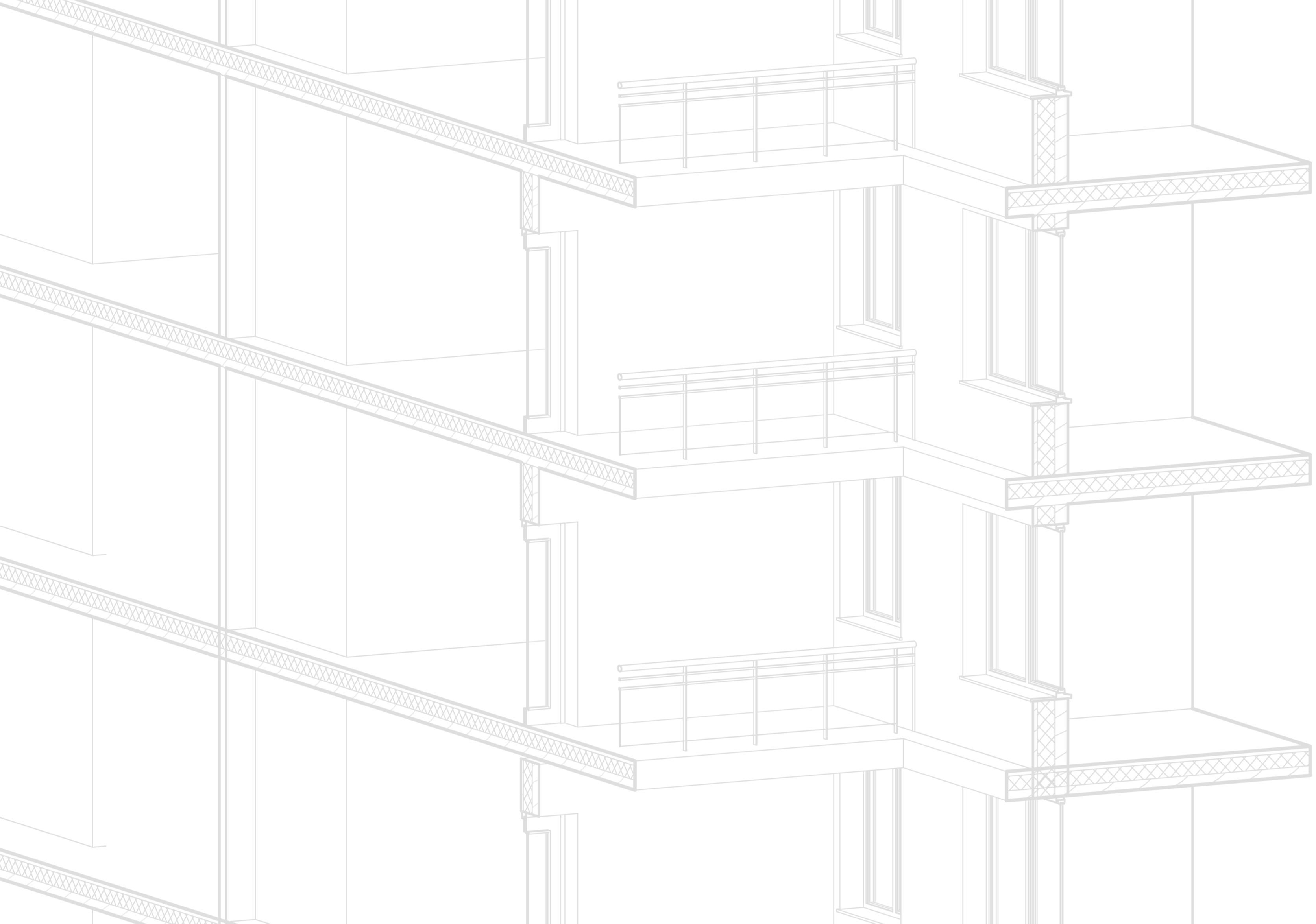
The Base case was improved by inputting materials envisioned for the project. That is cross laminated Timber, Green concrete and Wood fibre insulation The typical construction details of wall, roof and flooring of this type of construction is depicted in the sketches on the right Once the thermal envelope of the unit is improved, there is a drastic change in the fuel consumption From the monthly process fuel breakdown from the right, We can notice that January energy demand fell to 10KWh/m2. The achieved U-values for the walls is 0.16W/m2.k, floor is 0.17 W/m2.k and roof is 0.!8W/m2.k. These values are almost close to Passivhaus standard The U-value improvement beyond this increases the thickness of the elements which increases the carbon foot print of the building Hence a good balance between both were used for calculations
The windows were improved to triple glazing with argon filling to minimise incidental gains.


Improved through shading


case Fuel Breakdown
Since solar gains were the main reason for increased demand, To further improve the unit’s performance, shading devices were explored When the Slab was given a 600mm overhang, slight improvements were noticed By analyzing shade patterns on Summer and Winter scoliotics, When 300mm Box type shading projections were introduced on 3 sides of the window frame, the energy demand improved exponentially.
From the day light and Illuminance graph the reduced solar intensity compared to base case can be observed. The improved thermal envelope U-Values were kept constant for this simulation The Energy demand in January decreased to 6 3KWh/m2
The graphs on the right compare the three simulations to analyse how the performance of the unit has been improved. From the Fabric and Ventilation losses, Walls and Roof were losing more heat (-12W/m2 and -10W/m2) This was cut down by half in the improved case
For the Total energy demand of the unit (Hot water, lighting, Heating, cooling and Electricity), the base case was using 99 KWh/m2/yr When the Thermal Envelope was improved, this reduced to 54KWh/m2/yr and in the final improved case 38KWh/m2/yr was achieved which is better performance than Passivhaus standards.
Similarly, For the total Heating demand of the unit, the base case was using 41KWh/m2/yr, this reduced to 34KWh/m2/yr and in the final improved case 18 KWh/m2/yr was achieved which is close to Passivhaus standards


CLT is the new ecological timber that is being used in multiple places due to it flexibility and strength in construction It is engineered wood processed into boards and can be glued together to achieve the required thickness
The material has a good thermal conductivity value of 1 2W/m k, has more strength than its weight and can withstand harsher climates For these reasons, CLT is chosen as the structural loadbearing material for walls and as interior partition walls for this proposal.
It is a known fact that concrete posses goof thermal mass When used on site, concrete also acquires air tightness properties
Newer technologies have made the constituents of concrete less harmful They call it Green concrete It has recycles elements, more durable and produces less carbon dioxide This material can be used for foundations and for shear walls such as lifts and staircases. Also, there is a floating concrete manufacturing unit at Canary Wharf that is currently supplying cement derivatives for the wood wharf redevelopment. This reduces the transportation costs as well.
As the name suggests, wood fibre insulation is made from waste and recycled wood It is a natural and sustainable material with a good thermal conductivity of 0 04W/m k The material is permeable and lasts a life time once installed. It possess heat, cold and fire resistant properties. The cons of the material are it is not widely available and constitutes of higher embodied carbon compared to other natural insulation materials However since it has many positive aspects, it can be used as insulation material for this project Steico flex, eco merchant and Gutex are the closest vendors to site

Rendered plan of a typical floor constituting all typology units.

The walkway is made of concrete and Timber supported by a cast iron or steel hollow column.
Since the water is not moving tidal energy cannot be generated in usual methods. Newer technology is trying to cause rotation in blades with the help of a motor The idea is to generate three times the energy used for the functioning of the system
The detail below depicts how this system can be installed near the base of the footing The sketch also depicts the construction detail of the bridge.


Potential tidal energy source
Trees for shading and as wind Screens
PV Solar panels for Electricity and Solar thermal for hot water
Terrace gardens help evapotranspiration
Cutout acts as lightwell, escape for hot air, passive cooling from courtyard trees.
Green roof helps cool the building by absorbing radiation
Permeable surfaces help rainwater seepage into ground table to avoid flooding and surface run off
Cross-Ventilation ensures constant flow of fresh air.

STRATEGIES IN


