Biophilic Health Clinic
Connecting Nature to Health and Wellness
 By Megan SooHoo
1
Contents
Part I
Introduction: 4-5
Part II
Beginning: 6-7
Part III
Process: 8-11
Part IV
Plan:12-19
Part V
Structure: 20-23
Part VI
Design: 24-35
2
3
Built environments have the potential to both positively and negatively impact our health and wellbeing. Architects are becoming increasingly aware of the need for performative goals to be met that promote high quality health and wellbeing for the building occupants. Recent studies show that there are benefits from the articulation of design strategies that lie at the intersection of placemaking and biophilic principles.
In the beginning of the semester we were tasked with the design of a healthcare clinic for Virginia College of Osteopathic Medicine (VCOM). The school’s values align with the biophilic approach due to their philosophy of a holistic approach to healthcare that merges the mind and body. Biophilia “suggests that humans possess an innate tendency to seek connections with nature and other forms of life”. Studies show that the exposure to natural elements through biophilic design influences our mental and physical health in profound ways thus promoting staff wellness and productivity.
Upon approaching this project, I made it my main goal to include the three pillars of biophilic design: nature in the space, natural analogues, and nature of the space. I aimed to include many sources of natural daylight, provide visual connections to nature where applicable and utilize natural materials.
Part 1
Introduction
4
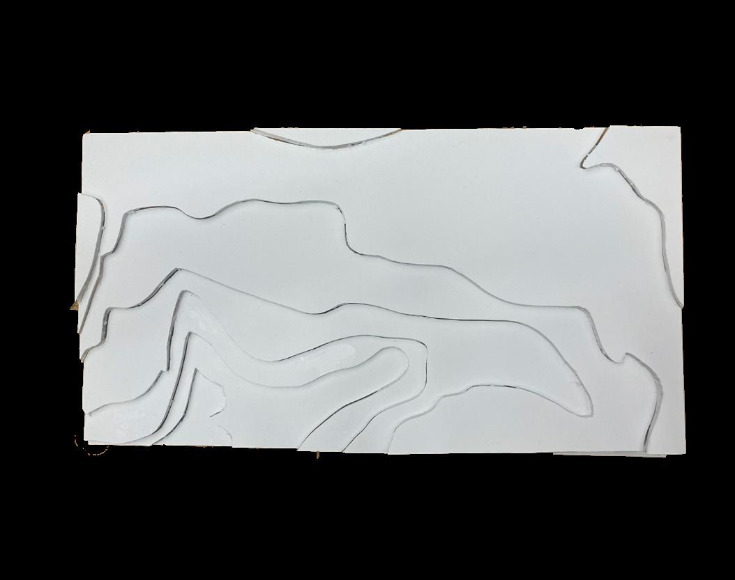
Mass Model Studies and Parti Diagram
Part II
Beginning
5
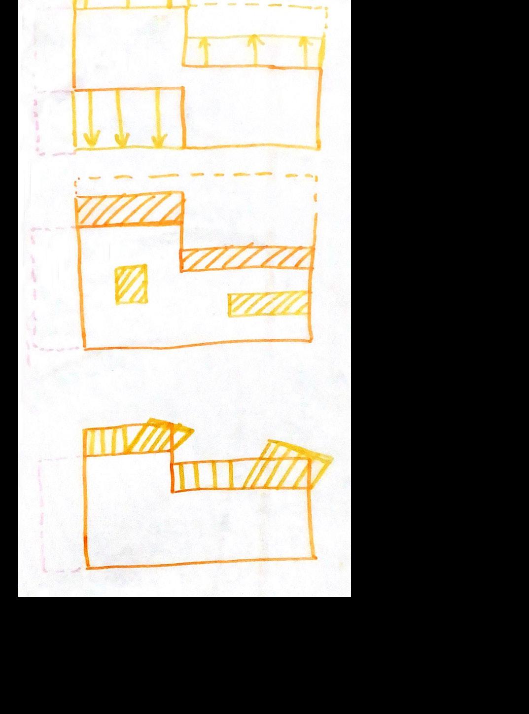
I began my mass model studies by analyzing different forms and how some of the components of the site, such as wind and daylight, could be utilized to advance the design of the health clinic. Throughout my analysis, I analyzed how the buillding would sit on the site, how views to the mountains can be maximized, how to take advantage of the warm summer breeze and block the winter winds, and how to maximize daylight to reach deep into the building.
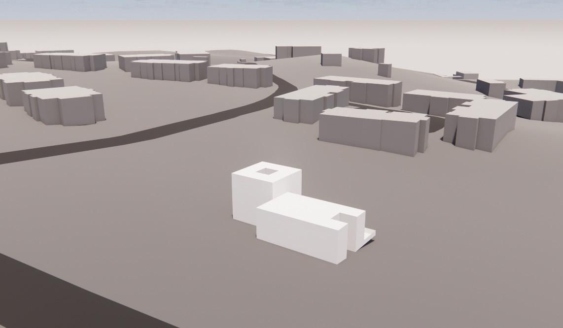
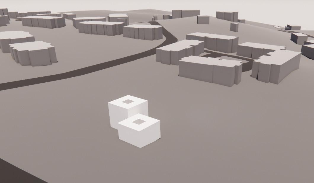
My parti model represents the organization of the building I came to in the end. The different colors is representative of the different structural components utilized to represent the two different parts of the building.

Beginning
6
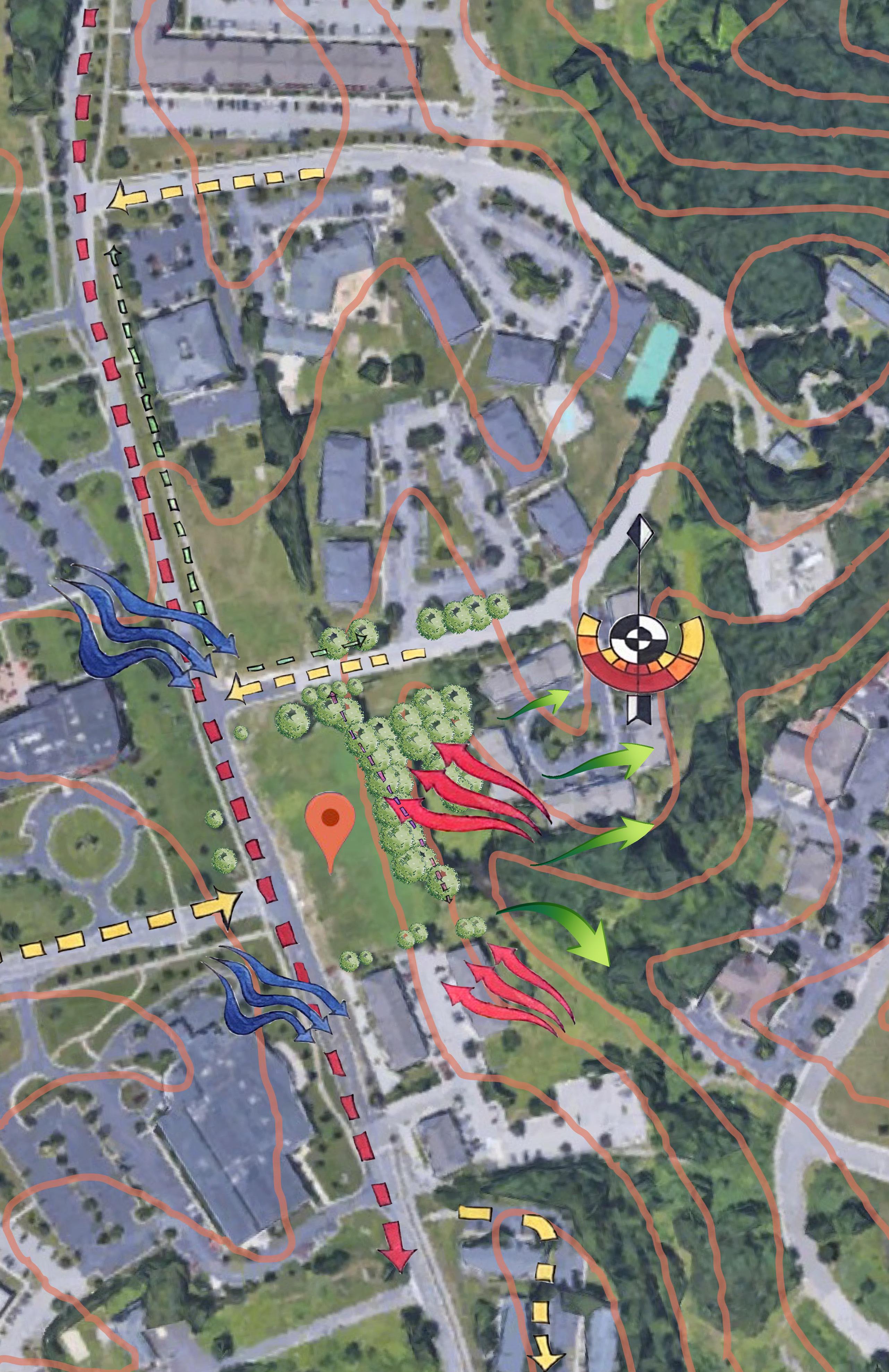
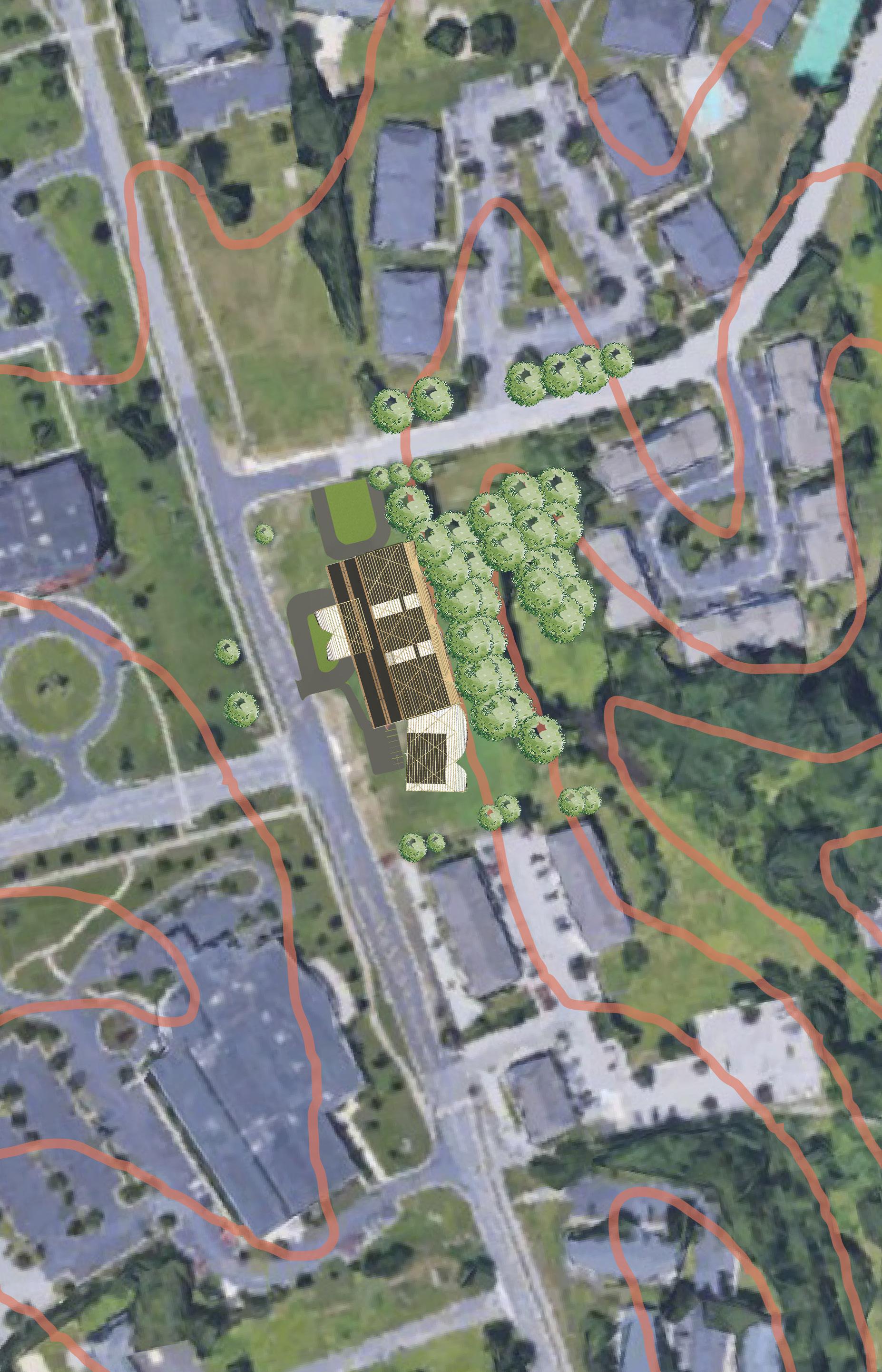
Site Analysis
Location and Climatic Factors
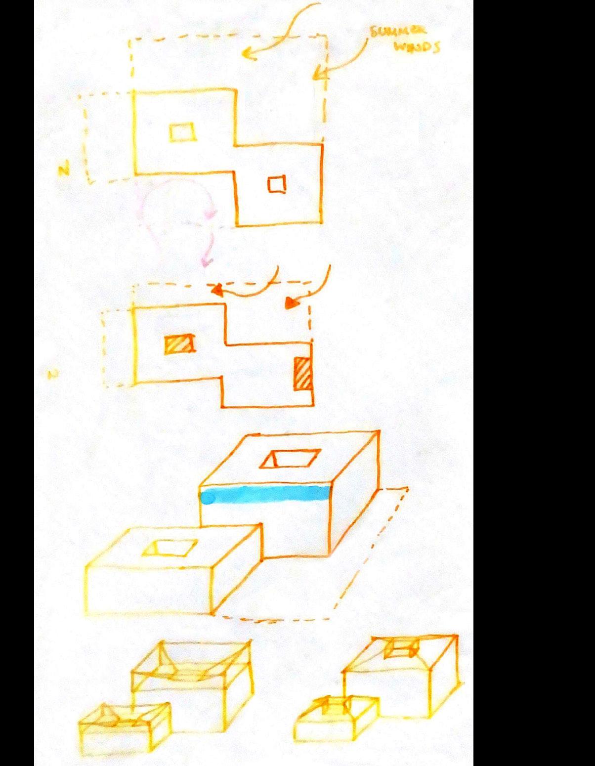
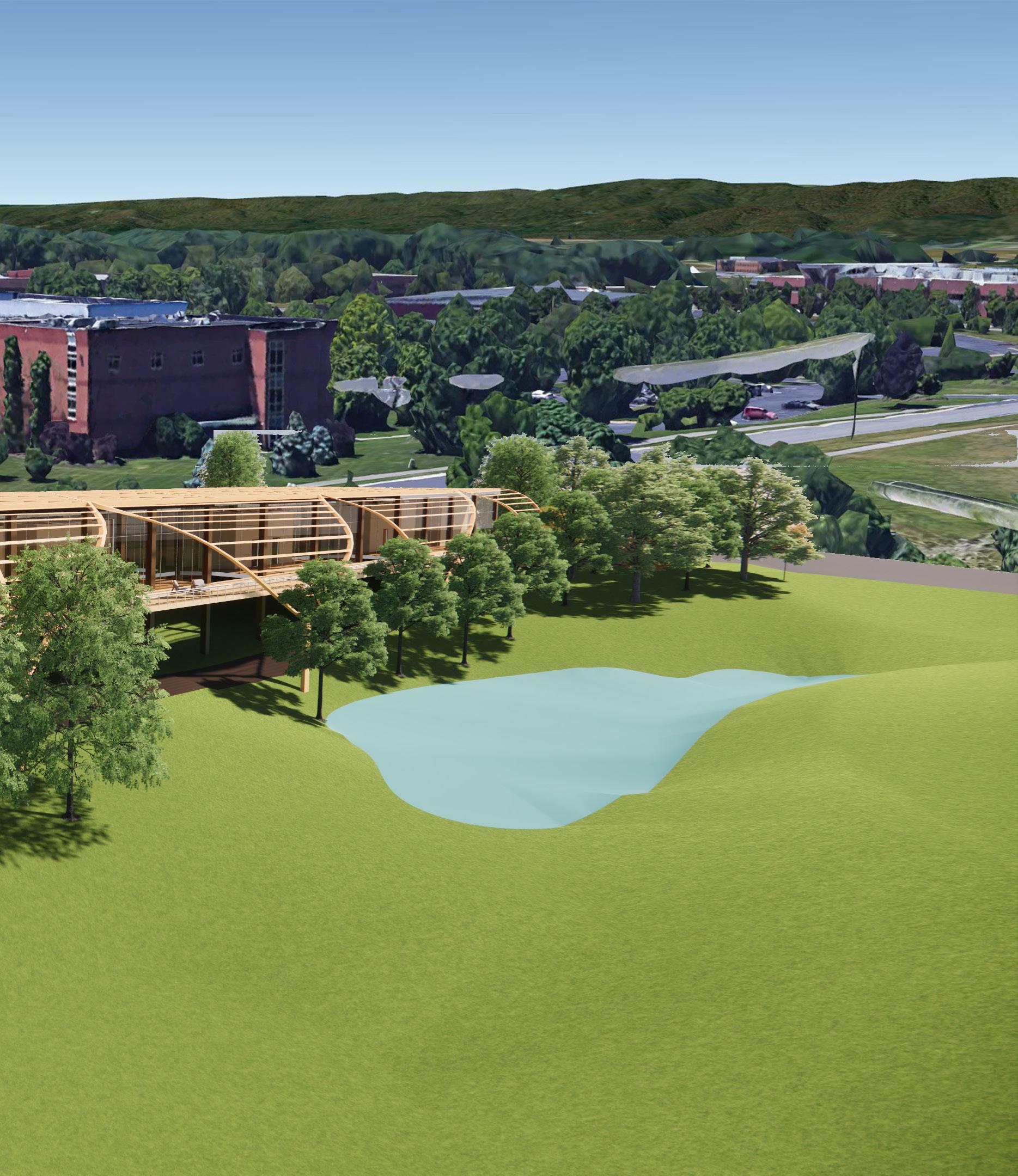
The site identified is located on a corner of South Knollwood Drive and Research Center Drive, adjacent to VCOM. My site analysis identifies heavier traffic on the main road, and lighter traffic on the side streets. Furthermore, the site is relatively flat on top and drops about 20’ along the treeline towards a pond. The site provides astounding views to Brush Mountains to the East which are indicated by the green arrows.
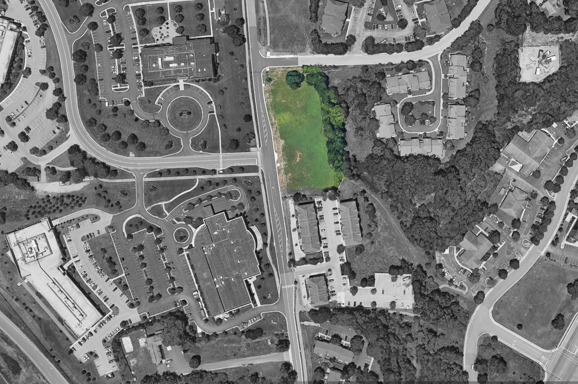
Further analysis of the climatic factors indicated harsh winter winds coming
from the North-West and cool summer breezes coming from the South-East. Additionally, the sun compass indicates the movement of the sun in the winter and the summer. Additionally, there is a pedestrian path along the tree line indicated in pink that challenges whether we should respect it or get rid of it.
The use of the summer breeze, the pattern of the sun, and the views to the moutains indicates high potential for an exterior space in the South-East side of the building.
Part III
7
Process 8
Program Analysis
My program analysis helped me wrap my head around the various rooms needed for the health clinic and the education center. Once I was able to determine the main areas, I was able to group how many supporting rooms each facility needed. This helped me determine which facilties needed more space. This also helped me decide to put the patient departments on one side of the building and the staff areas on the other. I also decided to put the education facilities in a separate building to reduce the traffic from the main building where there will be patients circulating throughout.
Part III
9
Process 10
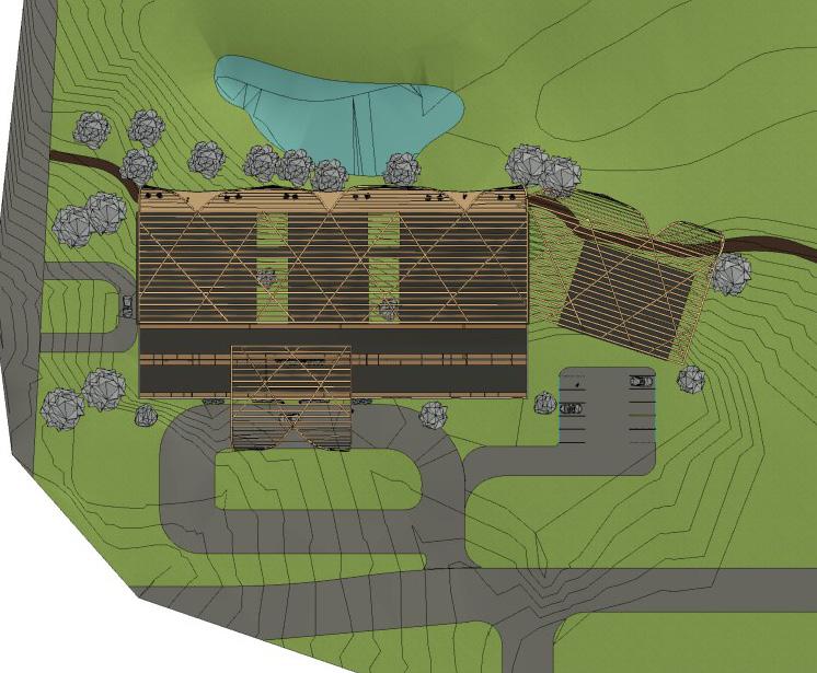
Site Plan
Part IV
11
Plan 12
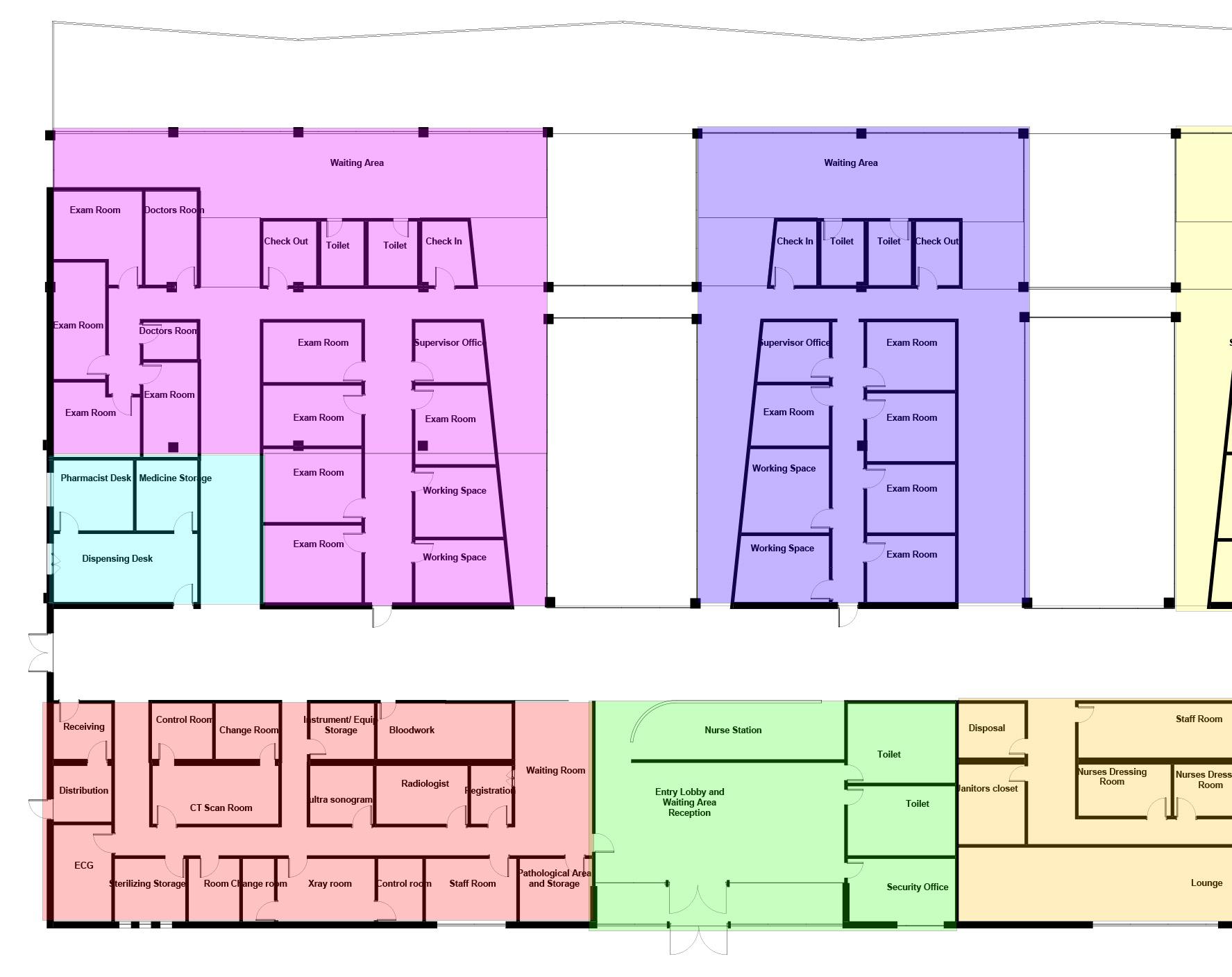
Programmatic Plan
Part IV
13
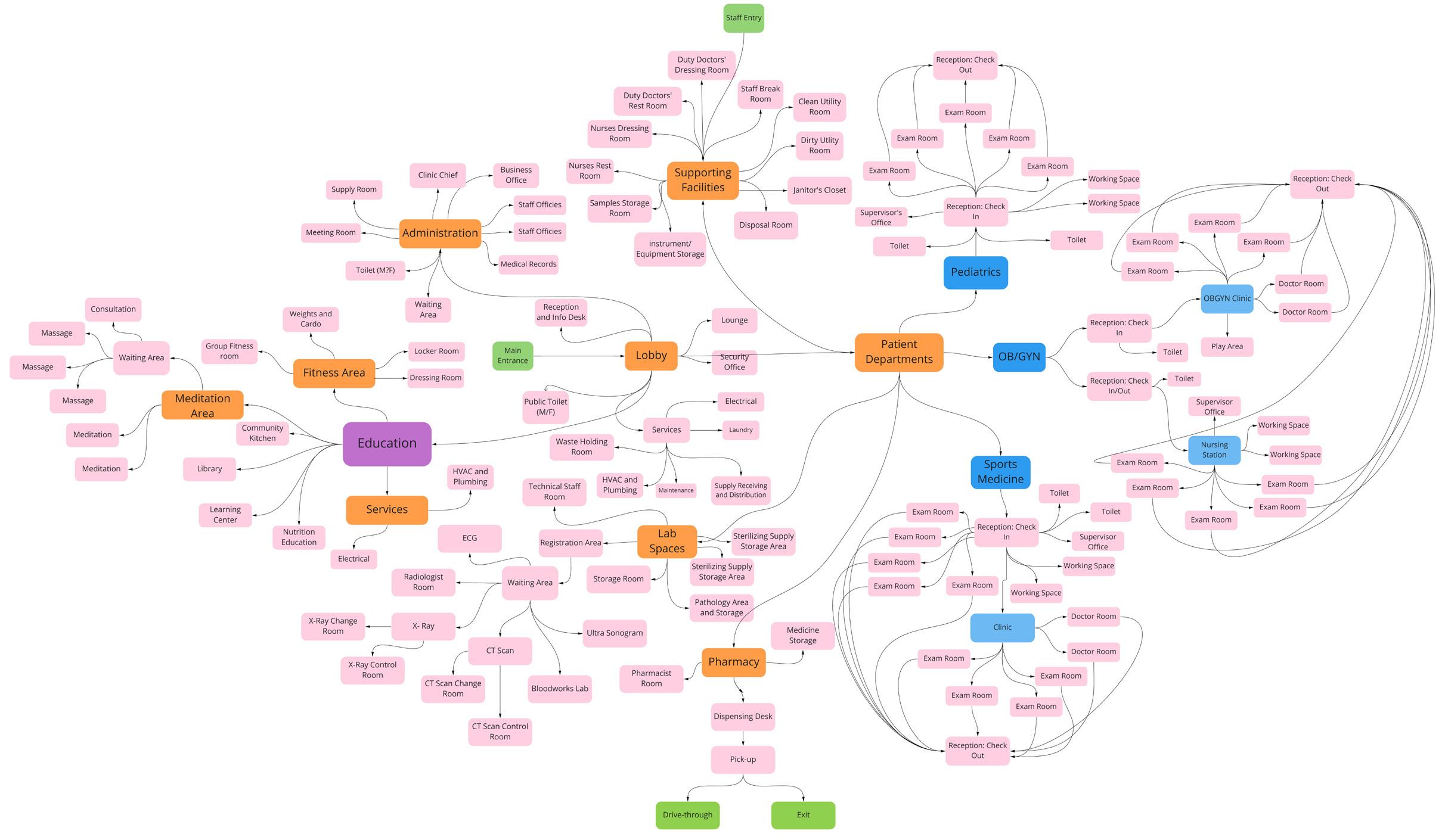
My plan is organized into two halves. The top half is dedicated to patient departments including: the pediatrics department, sport medicine and OBGYN. The patient departments were placed into three different sections because I wanted each department to have their own view of the courtyards as they traverse down the hallway to the check in. The views to the outdoors will help promote biophilia while simultaneously making the hallway appear bigger. Due to the fact that this is where a large portion of the patients will be visiting, the waiting rooms also have access to the balcony with views to the mountains. The blue section is the pharmacy where there is also a drive through so people don’t have to come inside to pick up a prescription. The green section on the right side is some of the supporting facilities. The red section are the labs and the orange are the staff spaces with an exit at the end of the hallway with access to the staff parking which allows them to be discrete if a doctor or nurse is late.
Plan
14
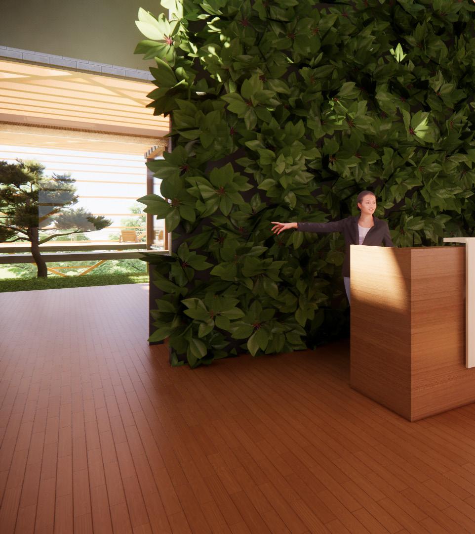
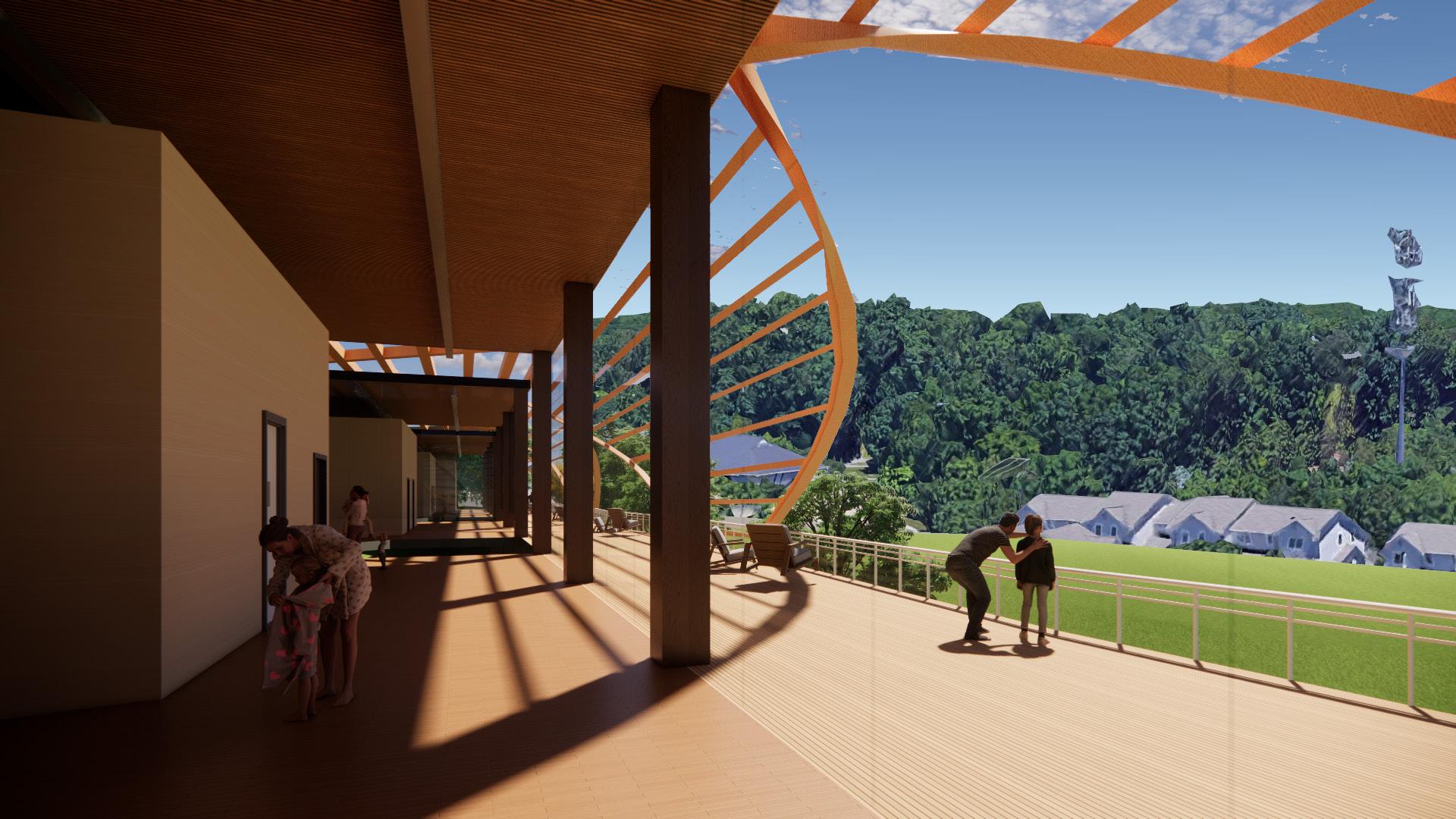
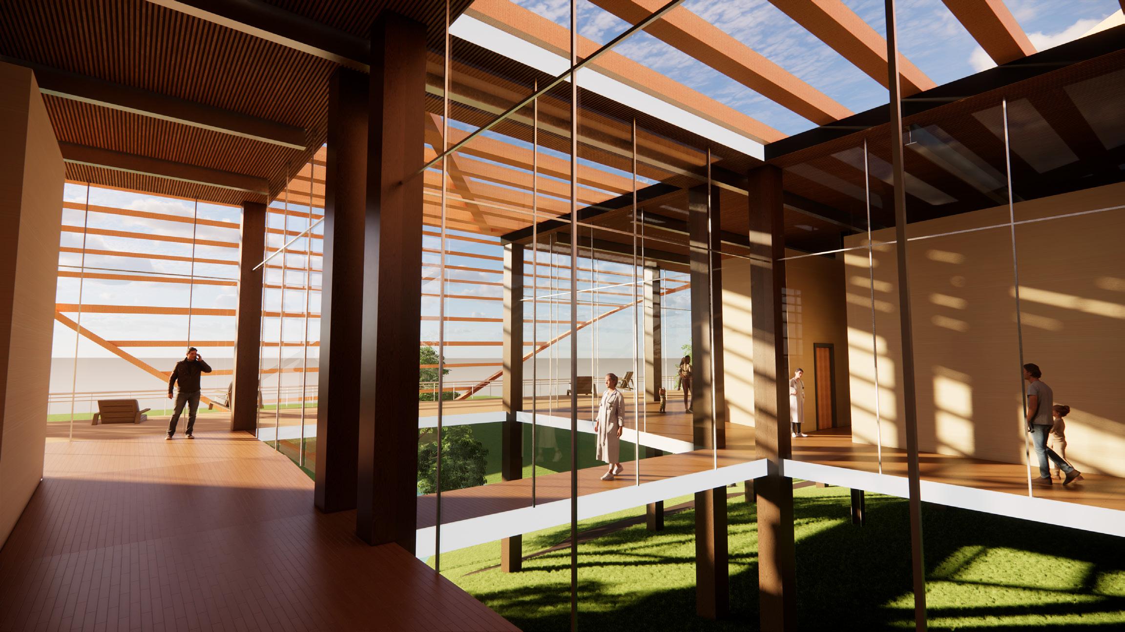
As the visitor enters through the main entrance, they are brought into the main lobby and immediately connected back to nature though the green wall located behind the receptionist’s desk. After being told where to go next, they are greeted by a courtyard with expansive views to the balcony out back. The two elements work
together to foster a biophilic connection and promote the connection to natural elements.
As the visitor continues down the long hallways to the check-in for each patient department, the hallway starts off small, leading the visitor to speculate what lies ahead. As they traverse down the hall,
Working Space Exam Room Exam Room Working Space Exam Room Supervisor Office Exam Room Exam Room Exam Room Exam Room Exam Room Exam Room Exam Room Exam Room Exam Room Exam Room Exam Room Doctors Room Doctors Room Check Out Toilet Toilet Check In Check In Toilet Toilet Check Out Working Space Working Space Pharmacist Desk Medicine Storage Dispensing Desk Supervisor Office ultra sonogram CT Scan Room Lounge Staff Nurses Nurses Dressing Room Pathological Area and Storage Staff Room Registration Change Room Control Room Instrument/ Equip Storage Radiologist Receiving Distribution ECG Sterilizing Storage Room Change room Xray room Control room Waiting Room Entry Lobby and Waiting Area Reception Waiting Area Waiting Area Bloodwork Toilet Toilet Security Office Janitors closet Disposal Nurse Station Part IV
15
Floor Plan
it begins to widen aiding in framing the view to the elevated level with views to the mountains. Through each curtain wall, the spectator is able to enjoy the shading element utilized outside the building. More over when the visitor is ready to leave, they are able to go down the hall opposite of where the entered, thus aiding in circulation.
Furthermore, after each check up visitors are able to stop by the pharmacy or lab before leaving which are located in the front half of the building.
The staff heavy circulated areas are located on the front- right side of the building. I aimed to give the staff their own section to reduce patientto-staff interactions which staff are off-duty and would like some privacy.
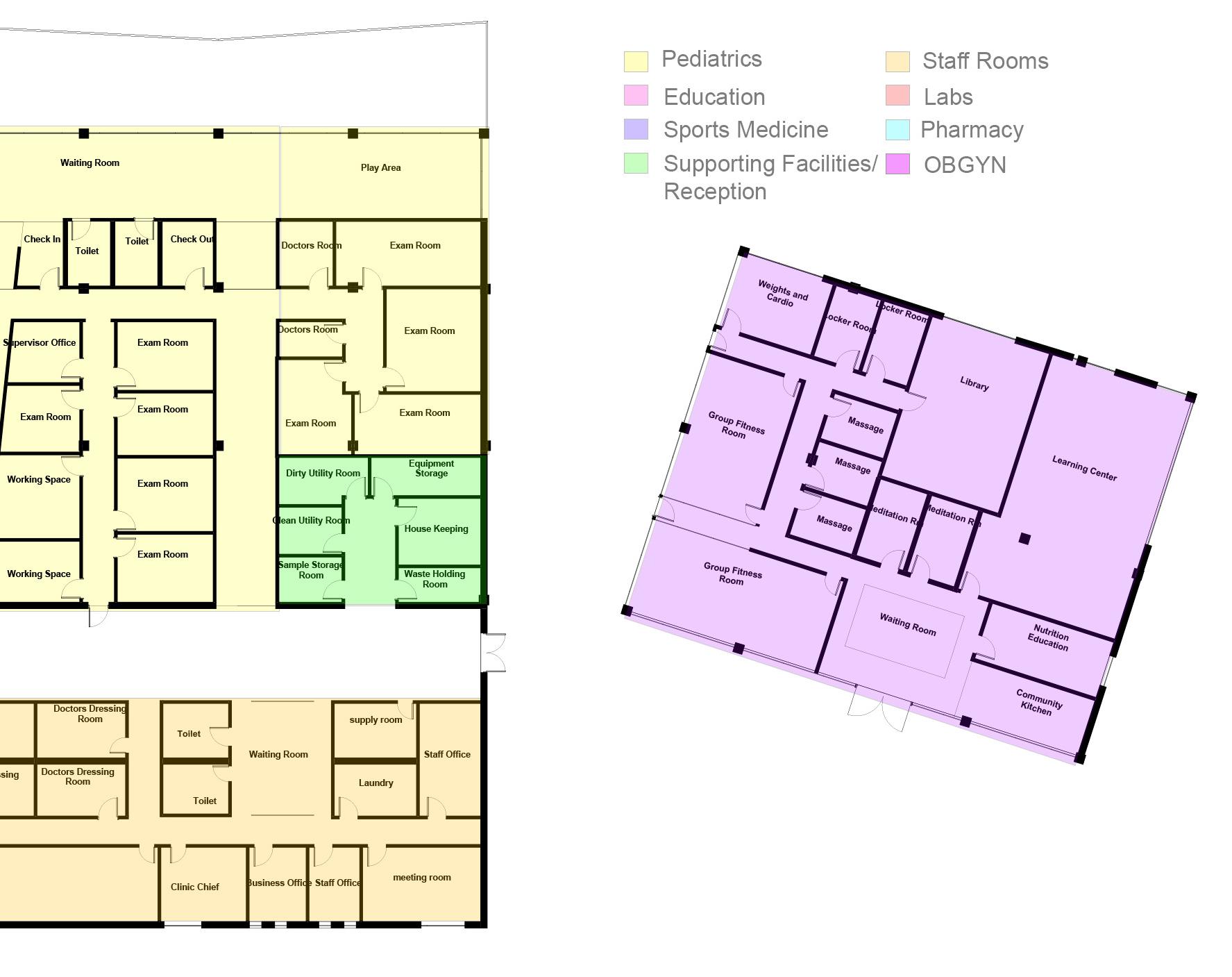
Sample Storage Room Clean Utility Room GroupFitness Room Weightsand Cardio LockerRoom LockerRoom Massage Massage Massage MeditationRmMeditationRm Library LearningCenter Nutrition Education Community Kitchen WaitingRoom Exam Room Exam Room Exam Room Exam Room Exam Room Exam Room Exam Room Exam Room Exam Room Doctors Room Doctors Room Check In Toilet Toilet Check Out Working Space Supervisor Office Working Space Business Office supply room Staff Office meeting room Toilet Toilet Dirty Utility Room Equipment Storage House Keeping Waste Holding Room Staff Office Laundry Clinic Chief Lounge Doctors Dressing Room Doctors Dressing Room Room Nurses Dressing Room GroupRoomFitness Waiting Room Waiting Room Play Area Plan 16
Working Space Exam Room Exam Room Working Space Exam Room Supervisor Office Exam Room Exam Room Exam Room Exam Room Exam Room Exam Room Exam Room Exam Room Exam Room Exam Room Exam Room Doctors Room Doctors Room Check Out Toilet Toilet Check In Check In Toilet Toilet Check Out Working Supervisor Working Space Working Space Pharmacist Desk Medicine Storage Dispensing Desk Supervisor Office Working ultra sonogram CT Scan Room Lounge Staff Room Nurses Dressing Room Nurses Dressing Room Pathological Area and Storage Staff Room Registration Change Room Control Room Instrument/ Equip Storage Radiologist Receiving Distribution ECG Sterilizing Storage Room Change room Xray room Control room Waiting Room Entry Lobby and Waiting Area Reception Waiting Area Waiting Area Bloodwork Toilet Toilet Security Office Janitors closet Disposal Nurse Station Part IV 17 Circulation Diagram
Sample Storage Room Clean Utility Room GroupFitness Room Weightsand Cardio LockerRoom LockerRoom Massage Massage Massage MeditationRmMeditationRm Library LearningCenter Nutrition Education Community Kitchen WaitingRoom Exam Room Exam Room Exam Room Exam Room Exam Room Exam Room Exam Room Exam Room Exam Room Doctors Room Doctors Room Check In Toilet Toilet Check Out Working Space Supervisor Office Working Space Business Office supply room Staff Office meeting room Toilet Toilet Dirty Utility Room Equipment Storage House Keeping Waste Holding Room Staff Office Laundry Clinic Chief Doctors Dressing Room Doctors Dressing Room Dressing GroupRoomFitness Waiting Room Waiting Room Play Area Plan 18
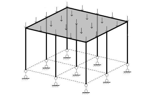
Structural Plan
The front half of the building is held up by three load bearing walls with hokie stone finish. The structure of the back half of the building cantilevers off the topography and utilizes a post-and-lintel structure. CLT columns are placed along a grid custom to each portion of the building.
Part V 19' - 8 3/4" 19' 8 3/4" 19' 8 3/4" 19' 8 3/4" 25' 11/16" 25' 3 11/16" 21' - 4" 21' - 4" 21' - 4" 20' 9" 25' 1/32" 25' 0 1/32" 25' 0 1/32" 25' - 10 7/32" 25' 10 7/32"
19
18'-531/32" 37'-109/16" 18'-531/32" 29'8 31/32" 29'8 31/32" Structure 20
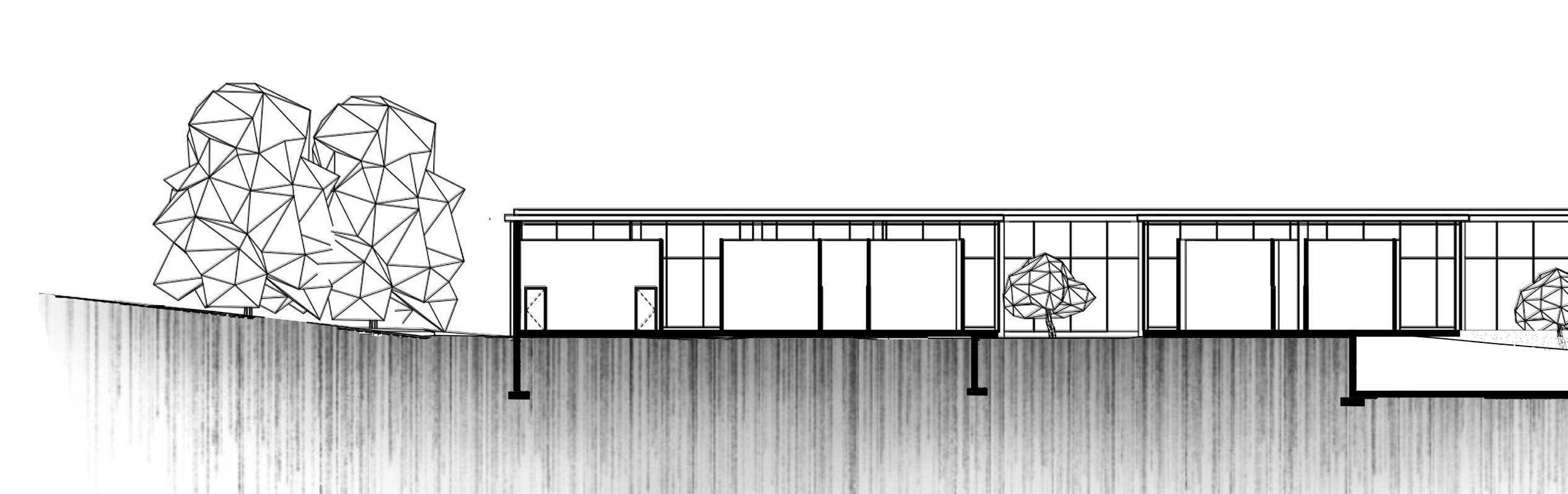
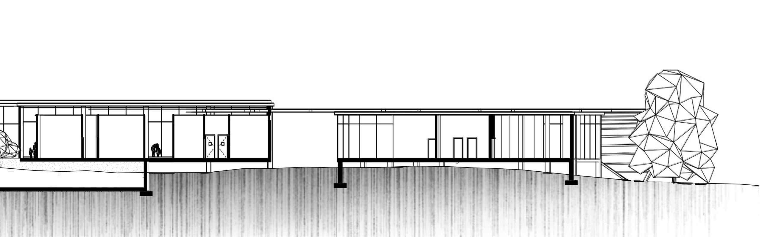
The two different structural systems are seen throughout both sections. At the bottom of the two you are also able to see the HVAC rooms located below two different parts of the building. The section along the lateral side of the building shows the load bearing walls and where the post-and-lintel portion of the construction begins. Moreover, you are able to see the drop down ceilings which allow light to filter into the deeper parts of the building. Similarly the lighter half of the building’s roof raises where it meets the shading element also allowing light to penetrate deeper into the building. From the longitudinal section, one is able to see how the building sits on the topography and how you are able to catch glimpses of the curtain wall from the main hallway.
Part V
21
Sections
StructureSample Storage GroupFitness Room Weightsand Cardio LockerRoomLockerRoom Massage Massage Ma sage Meditation Meditation Libra LearningCe Nutrition Education Community itchen Working Space WaitingRoom Working Space Medicine Storage Doctors Dressing Nurses Dressing GroupFitness Room Entry Lobby and Waiting Area Waiting Area Waiting Room 22
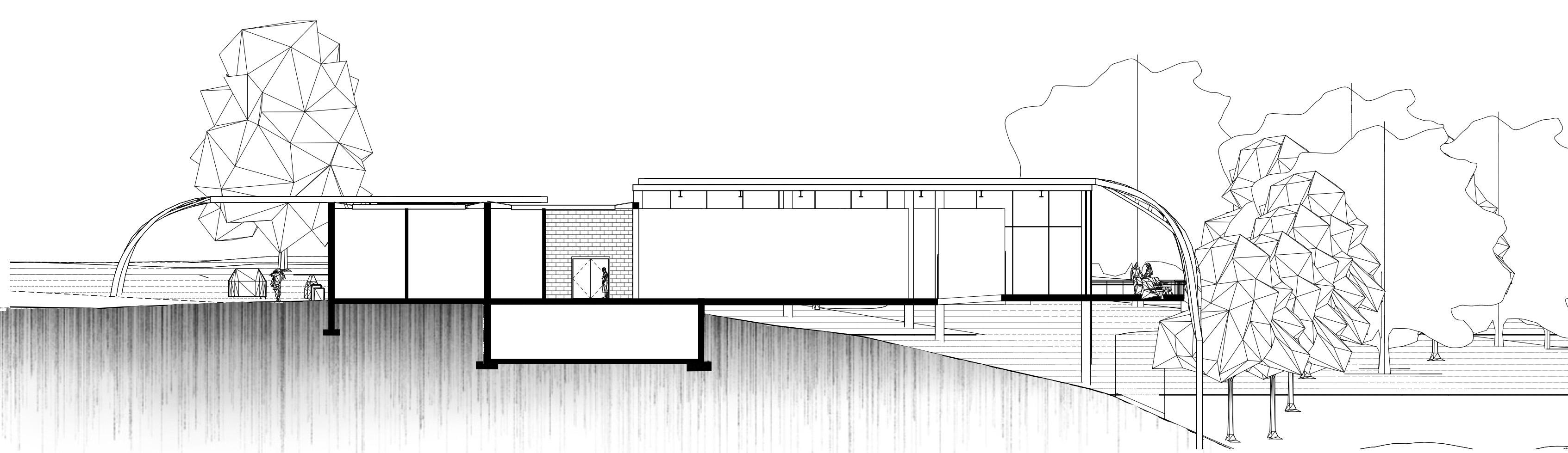
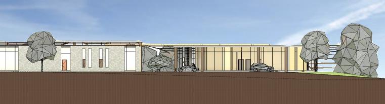
Elevations

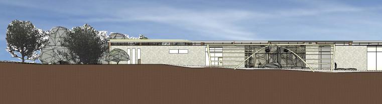
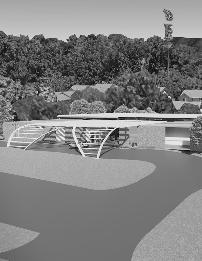
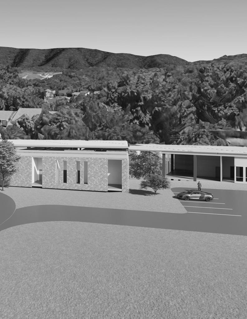
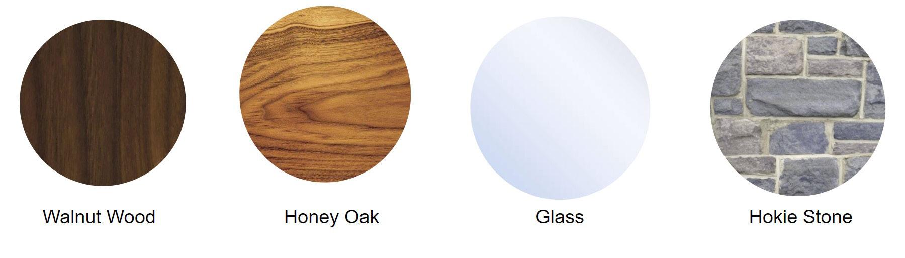
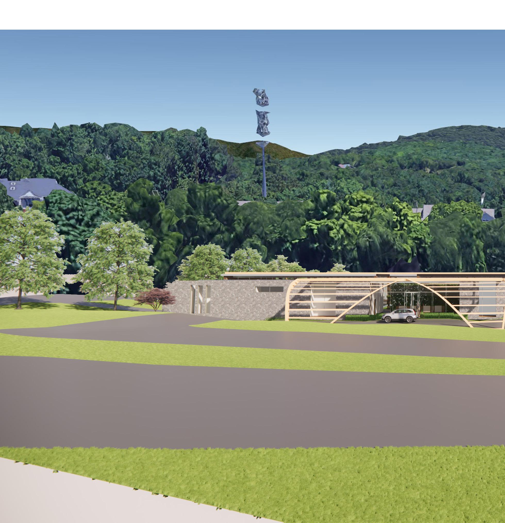
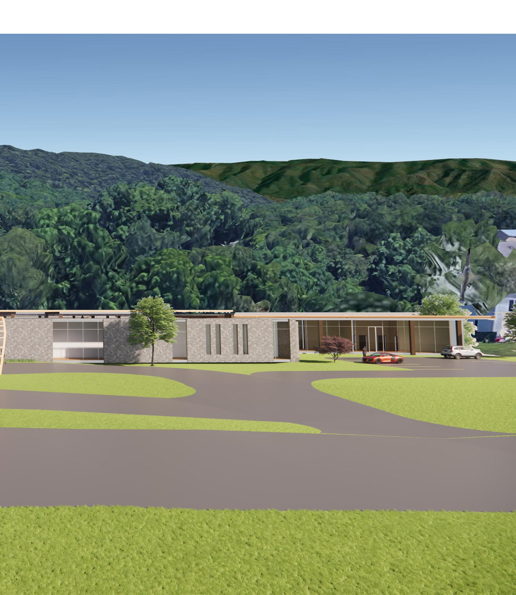
From my elevations you are able to see the various materials I chose to use. I utilized the two different materials to represent the transition throughout the building. Upon entering the building, the material I chose to use is Hokie Stone. Utilizing the surrounding context, the Hokie Stone aids in showing that the building is connected to VCOM and Virginia Tech. Moreover, the hokie stone is a heavy material and mataphorical of the building being grounded. As one moves throughoout the building toward the back half, they are surrounded by much lighter materials such as Walnut Wood, Honey Oak and Glass. This is representative of the building transitioning and cantilevering off the topography. Furthermore, the different materials aids in representing the two different structural elements utilized.
I aimed to utilize only natural materials throughout my project in order to promote biophilia. Wood doubles as a building material and a structural element which can aid in creating a unique warmth and feeling of comfort for occupants. Furthermore, my goal for the use of my materials was to bring the outdoor inside and aid in reconnecting occupants to a healthier outdoor environment.
Part VI 23
West Elevation
Design 24
South Elevation
Main Lobby
Part VI 25

Design 26
South Brisbane, Queensland, Australia
27 Part VI
Inspiration
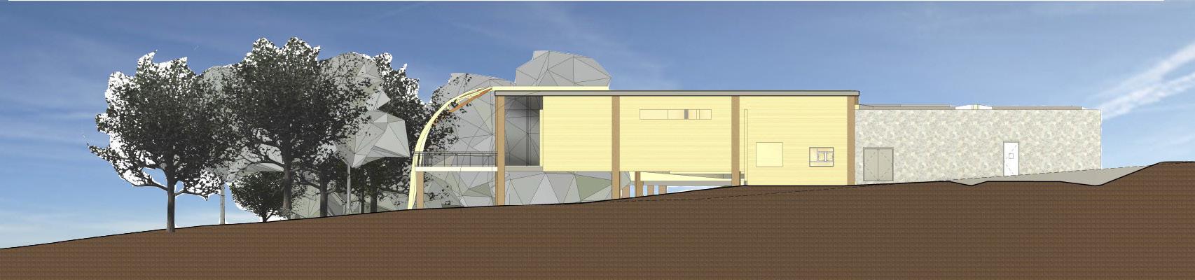
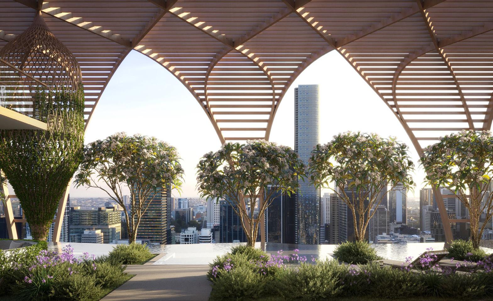
Upper House by Koichi Takada Architects in
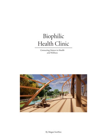
I wanted the shading element inspired by Upper House’s to be representative of the trees in the area. The organic element winds its way down the balcony and helps ground the structure to the topography below similar to roots of a tree. Furthermore, the wooden elements twist and intertwine to become a shaded element to the various outdoor spaces througout the building.
28 Design
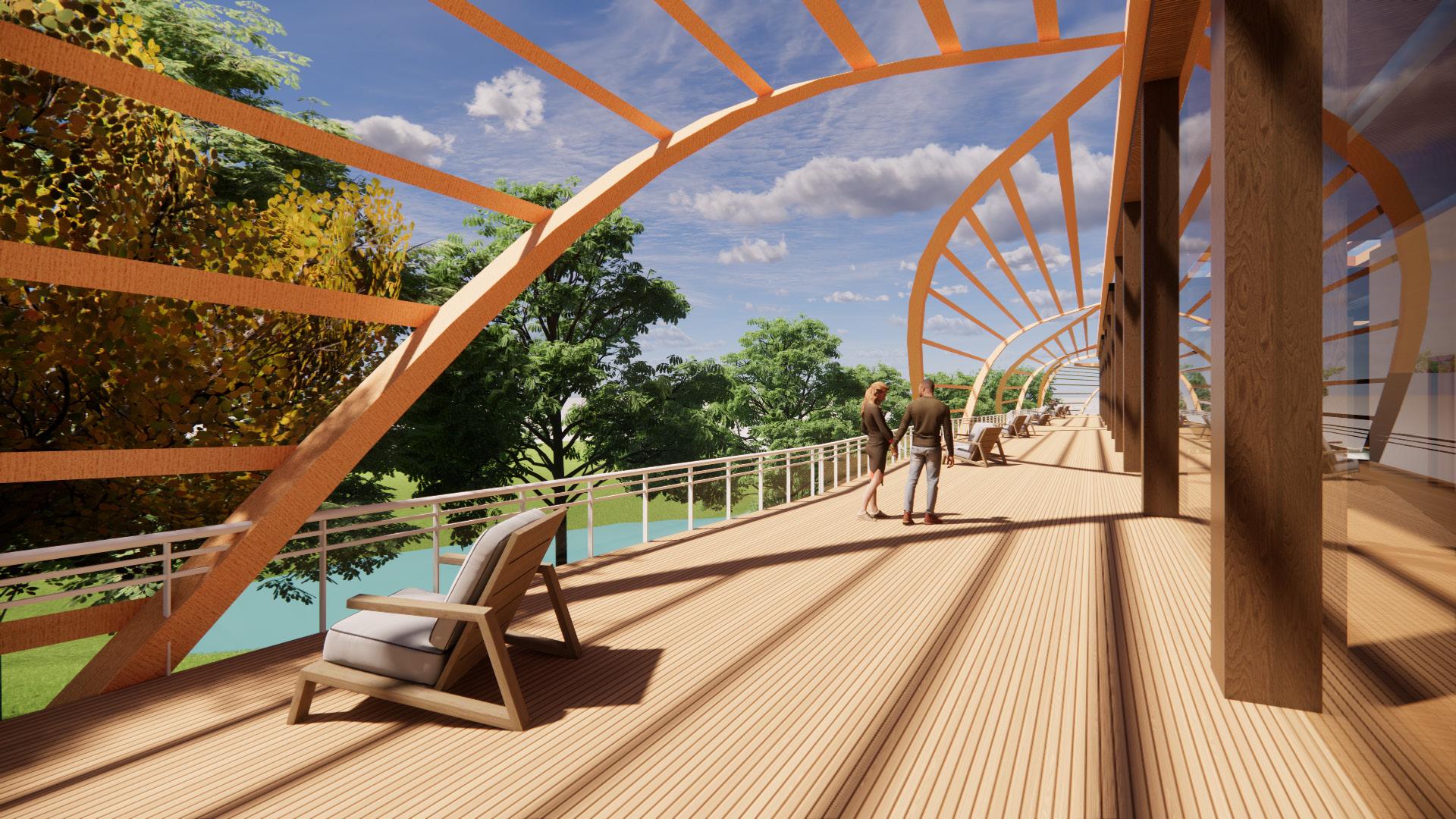
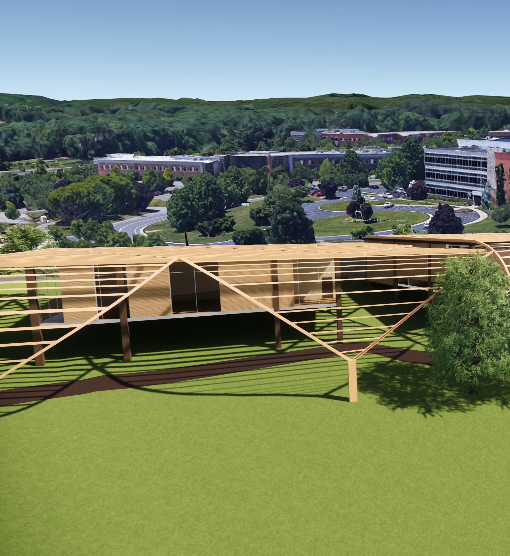
The shading element extends to the education center connecting the two buildings while also providing an interesting feature for the path between the two existing apartment complexes.
29 Part VI
30 Design
31 Part VI
32 Design
33 Part VI
34 Design