AXIALFLUXTHREEPHASEPERMANENTMAGNETMOTOR
AlexMayer-Sanchez CaliforniaPolytechnicStateUniversitySanLuisObispo ElectricalEngineeringDepartment SanLuisObispo,CA93405amayersa@calpoly.edu
ABSTRACT
Within this paper, I will explain the background of axial flux type motors, give background on the highest performance axial flux motors on the market, and show my replicated design and results with simulation. My simulated results will be calculated using Ansys Electronics Desktop with Maxwell 3D transientsolutions.
1.INTRODUCTION
Typically,motorsuseradialflux,wherethe airgapbetweentherotorandstatorisbetweenthe twocomponentsradiuses.Inanaxialfluxmotor, thegapbetweentherotorandthestatorisparallel totheaxisofrotation.Oneadvantageofthis configurationisgreaterpowerdensity,makingit idealforautomotiveandaviationpurposes. Imaginetwomotors,bothwiththesamestatorofa specificdiameter,buteachusingdifferentrotor configurations.Usingaradialfluxconfiguration, therotorwouldhavetobesmallerindiameterthan thestator,butinaxialconfiguration,therotoristhe samediameterasthestator.Therefore,theaxial fluxrotor,havingalargerradius,producesmore torquethantheradialconfiguration.
2.YASAMOTORS
YASAisaBritishelectricmotor manufacturerownedbyMercedes-Benz,andthey supplyelectricmotorsfortheirparentcompany,as wellasotherhybridhypercars.Theirmotorscan outputverylargeamountsoftorque,soafew examplesoftheirapplicationaretheFerrariSF90, Ferrari226GTB,andKoenigseggRegera. Ultimately,themotorIdesignedissimilartothe designoftheYASA750,whichtheyclaimcan outputamaximumtorqueof800Nm,butonlyfora shortduration.[1]Andwhenapplyingcontinuous torque,themotorcanoutput400Nm,consuming 70kWofpoweratasynchronousspeedof 3000rpm.[1]
3.MYYASATYPEMOTOR
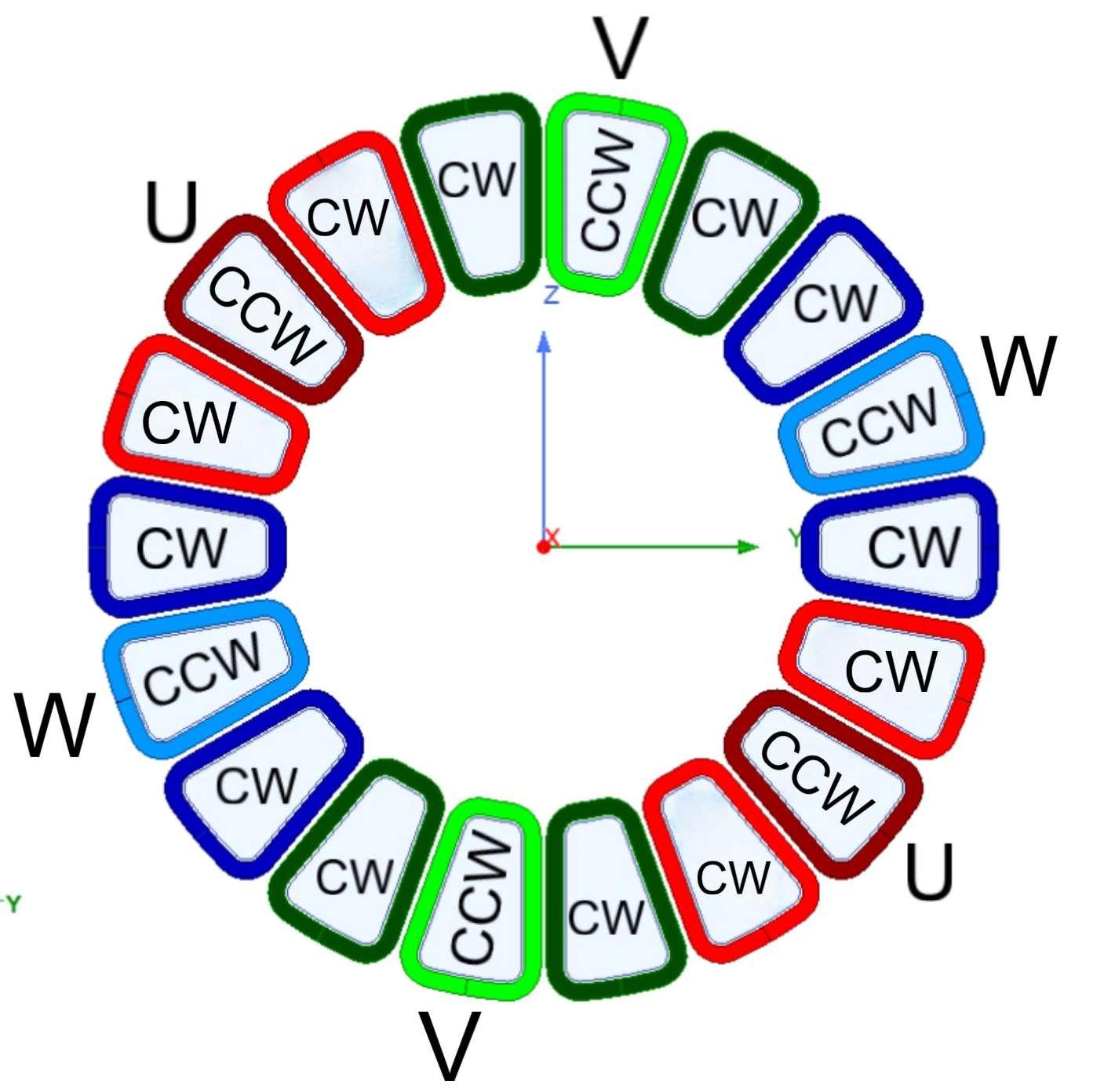
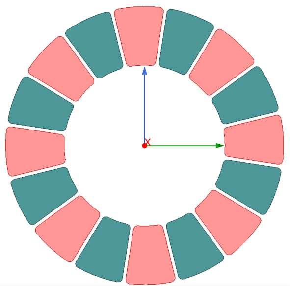
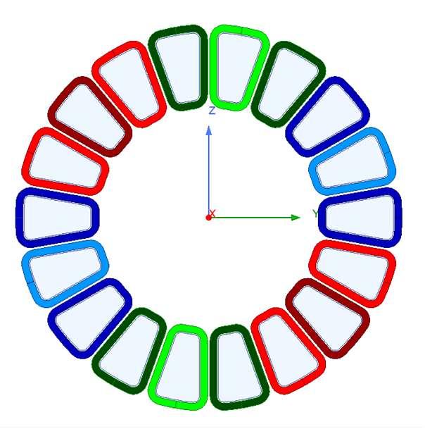
In Yasa’s data sheet, they do not specify many characteristics of the motor besides what the motor can output mechanically. Therefore, in my replication of the motor, I was more so designing my own axial flux motor in order to see if I could match or exceed Yasa’s outputs. So, the pole configuration of my motor uses an 18 pole stator of windings and a 16 pole rotor of permanent magnets,bothshowninfigure1.and2.
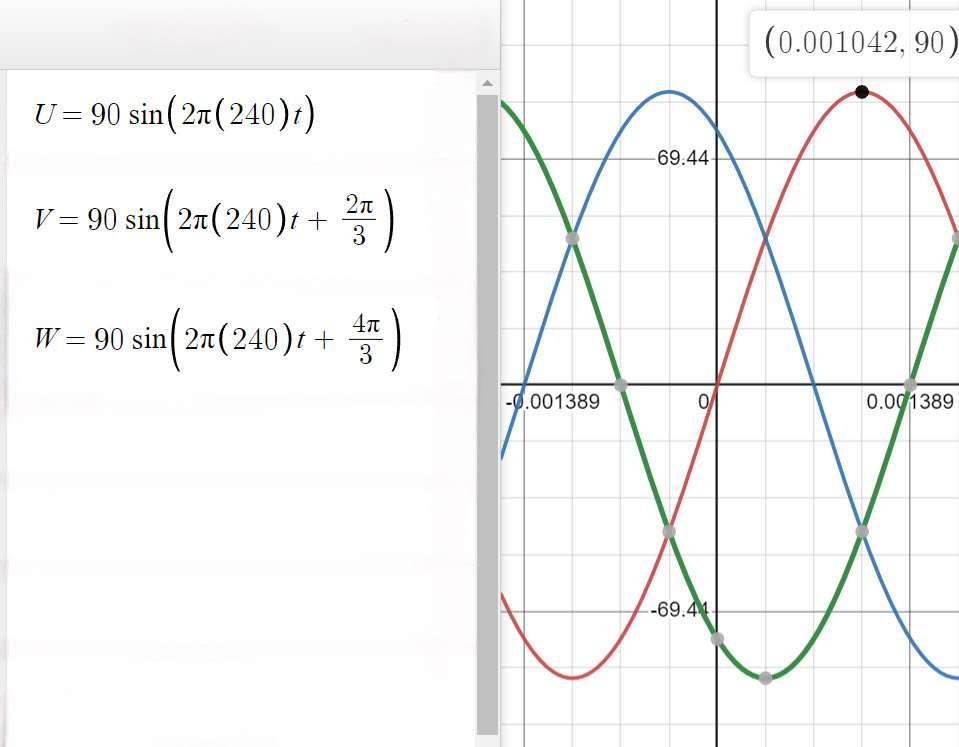
Furthermore,thesewindingshavea specificconfigurationandcurrent,creating excitationinthestator.Therearethreephasesof sinusoidalACcurrent,labeledU,V,andW.These runat240Hz,are120degreesapart,andare injectedintothe22turnwindingsat90Ampspeak, asshownbyFigure3.However,itisalsovery importanttoconfigurethewindingsineachphase properly.Theyareconnectedinawye configurationandalternatewithineachphaseina specificpatternsuchthattheexcitationcausesthe motortorotate.Figure4.AndFigure5.illustrate thecrucialpatternofthiswinding.
Figure5.PhysicalSeriesWYEWindingPattern

With this configuration, running an electric frequency of 240Hz, the synchronous speed of this motoris1800rpm.
4.SIMULATION
Using Ansys Electronics Desktop, you can import the geometry of an electric motor and apply definitions to certain objects. You can define their materials, their electric currents, their magnetic fields, eddy currents, rotational bands, etc. With all of this information, the Maxwell 3D transient simulation can do many steps of finite element analysis at different times and compile them to return a simulation of the motor rotating under the excitation of the electric power. I was able to capture some data, but the data sets I have are somewhat limited. This is due to only having personal access to the student software; therefore my simulations were ultimately run on a virtual computer lab, which was unable to handle large amounts of time steps for the finite element analysis.

My first simulation was done in order to test whether the excitations were functioning properly and creating a magnetic field. So, I ranthe setup I had at time steps of 0.7ms for 7ms. With this time step, I could capture the three phase AC input and the flux linkage, shown in Figure 6. and Figure 7. respectively. With this set of data, I could also create an animation of the magnetic field magnitude lines created by phase U of the motor seen in Figure 8. (animation only visible in word formatnotpdf)
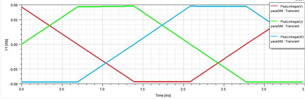
Figure8.PhaseUFieldMagnitudeLines
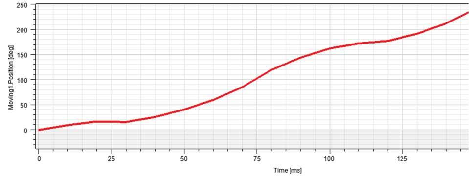
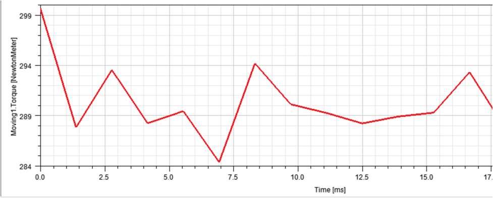
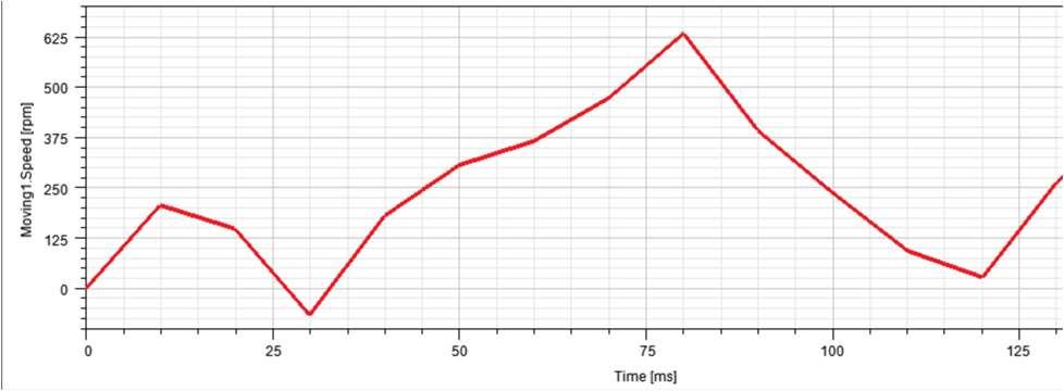
For my second simulation, I wanted to capture more data portraying the machine in motion, but the limitations of my processing power when simulating meant I had to sacrifice time for sampling resolution or sampling resolution for time.So,thesecondsimulationwas0.15slongwith time steps of 0.01s, and from this I found that the motor only rotated about 240 degrees in the process, as shown in Figure 9. As for the speed and torque of the motor, I believe the software gets confused when the sampling rate is too low, so it makes the graph choppy and jumpy, but I included them in Figure 10. and Figure 11. respectively. I think that in order to capture this mechanical data properly, I need access to the full software on my local device, because it has the processing power necessary to complete a simulation over a longer period with a finer sampling resolution. I believe that with such parameters for the simulation of my motor, the mechanical data results would be comprehensible, whereas the current results, when getting to higher order calculations like those for speed and torque, become unclear. However, it does appear that the torque of the motor ripples around 300Nm, which compared to the YASA 750, isareasonableresultbeingrunat90Ampspeak.

4.CONCLUSION
Firstly,Ineedtorunlongersimulationsto getmoredataofthemotorat1800rpm.Iamin contactwiththeAnsysAcademicProgram Manager,thankstomutuals,andtheysaidthey couldpossiblyprovidemewithtemporaryaccess keys.Oddly,theysaidtheywereconfusedasto whythestudentsoftwaredoesnotletmerun transientsolutions,sincetheythoughtotherwise,so onSunday,IsentthemtheerrorcodesIwas receiving.However,theyhavenotrespondedtomy emailssinceSunday3/19/23.
Still,Iamproudofmydesign,drawing ideasfromleadingindustrytechnologytocreatea machineofmyown.Andalthoughthesesimulated resultshavelimitedsampling,Iamproudofmy abilitytodefineamachinelikethisinAnsys.
Overall,AxialFluxMotorsareverypower dense,sodesignerswillbetakingadvantageofthis configurationforexcitingvehicleapplicationsin thefuture.Therefore,learningtouseAnsyshas mademefeelconfidentthatIcancontributeto creatingthesekindsofinnovativedesignsinthe future.
REFERENCES
[1] “750RElectricMotors-YasaLimited.” 750 R Electric Motors,YASALimited, https://www.yasa.com/wpcontent/uploads/2021/05/YASA750RDatasheet-Rev-11.pdf.