
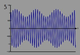
Problem 1: An AM (amplitude-modulated) radio signal fAM(t) is described by where faudio(t) is the audio signal, sin (Ωct) is known as radio-frequency carrier signal (fc = 500 – 1600 kHz - the AM band), and a is a positive constant that determines the modulation depth. (Note that we require |afaudio (t)| < 1 otherwise we have overmodulation.) the following figure shows an AM signal with an “audio” waveform that is a simple low frequency sinusoid. You can see how the audio signal “modulates” the amplitude of the rf signal.
fAM(t) = (1 + afaudio (t))sin (Ωct)
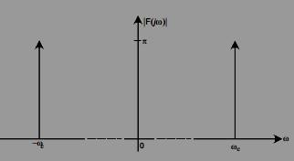
(a) Sketch the magnitude of the Fourier transform of fAM(t) when faudio(t) = 0.
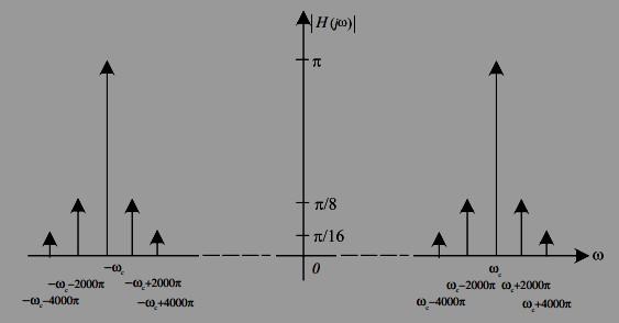
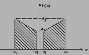
(c) Use your result from (b) to generalize, and sketch the magnitude spectrum of fAM(t) when faudio(t) has a spectrum (again let a = 0.5):
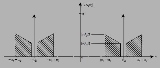
Answer: The following generalizes the results of part (b)
(d) If faudio has a bandwidth B = Ωu − Ωl, what is the bandwidth of a band-pass filter that would be necessary to select the signal fAM(t) out of all the other AM radio stations?
Answer: From the above figure it can be seen that the required bandwidth is 2ωu rad/s.
Problem 2: We generally ignore in the phase response in filter design. Although you might wish for a “zero-phase” filter, you can see from the class handout on causality that a filter with a purely real frequency response is acausal, and as such cannot be implemented in a physical system. The following are a pair of tricks that may be used to do “off-line” zerophase filtering of recorded data. (Note: these methods are used frequently in digital signal processing - it is difficult to do this in continuous time.) Assume that you have a filter H(jΩ) with arbitrary phase response H(jΩ), and that your input signal is f(t) is recorded on a taperecorder that can be played forwards or backwards. Method (1) 1. Pass f(t) through the filter and record the output g(t) on another tape recorder. 2. Play g(t) backwards through the filter (that is the filter input is g(−t)) and record the output x(t).
Heq = |H(jω)| 2 which is real, that is with zero phase shift.
Method(2) 1. G(jω) = F(jω)H(jω). 2. X(jω) = F(jω)H(jω).
3. Y (jω) = G(jω) + X(jω) = F(jω)H(jω) + F(jω)H(jω) = 2F(jω) { ℜ H(jω)}.
The equivalent transfer function is Heq = 2 {H(j ℜ ω)} which is real, that is with zero phase shift. Note that because it squares the frequency response magnitude, method (1) will have a sharper cut-off characteristic than method (2).
