
Solution 2.1
Design a problem, complete with a solution, to help students to better understand Ohm’s Law. Use at least two resistors and one voltage source. Hint, you could use both resistors at once or one at a time, it is up to you. Be creative.
Although there is no correct way to work this problem, this is an example based on the same kind of problem asked in the third edition.
Problem
The voltage across a 5-k Ω resistor is 16 V. Find the current through the resistor.
Solution
v = iR i = v/R = (16/5) mA = 3.2 mA
Copyright © 2017 McGraw-Hill Education. All rights reserved. No reproduction or distribution without the prior written consent of McGraw-Hill Education.
Solution 2.2
p = v2/R → R = v2/p = 14400/60 = 240 ohms
Copyright © 2017 McGraw-Hill Education. All rights reserved. No reproduction or distribution without the prior written consent of McGraw-Hill Education.
Solution 2.4
(a) i = 40/100 = 400 mA
(b) i = 40/250 = 160 mA
Copyright © 2017 McGraw-Hill Education. All rights reserved. No reproduction or distribution without the prior written consent of McGraw-Hill Education.
Solution 2.6 n = 8; l = 8; b = n + l –1 = 15
Copyright © 2017 McGraw-Hill Education. All rights reserved. No reproduction or distribution without the prior written consent of McGraw-Hill Education.
Solution 2.7
6 branches and 4 nodes
Copyright © 2017 McGraw-Hill Education. All rights reserved. No reproduction or distribution without the prior written consent of McGraw-Hill Education.
Solution 2.8
Design a problem, complete with a solution, to help other students to better understand Kirchhoff’s Current Law. Design the problem by specifying values of i a , i b , and i c , shown in Fig. 2.72, and asking them to solve for values of i 1 , i 2 , and i 3 . Be careful specify realistic currents.
Although there is no correct way to work this problem, this is one of the many possible solutions. Note that the solution process must follow the same basic steps.
Problem
Use KCL to obtain currents i 1, i 2, and i 3 in the circuit shown in Fig. 2.72 given that i a = 2 amps, i b = 3 amps, and i c = 4 amps. Solution
Copyright © 2017 McGraw-Hill Education. All rights reserved. No reproduction or distribution without the prior written consent of McGraw-Hill Education.
Solution 2.9
Find 123 , i, and i i in Fig. 2.73.
2.9.
Solution
Step 1. We can apply Kirchhoff’s current law to solve for the unknown currents.
Summing all of the currents flowing out of nodes A, B, and C we get, at A, 1 + (–6) + i 1 = 0; at B, –(–6) + i 2 + 2 = 0; and at C, (–2) + i 3 – 2 = 0.
Step 2. We now can solve for the unknown currents, i 1 = –1 + 6 = 5 amps; i 2 = –6 – 2 = –8 amps; and i 3 = 2 + 2 = 4 amps
Copyright © 2017 McGraw-Hill Education. All rights reserved. No reproduction or distribution without the prior written consent of McGraw-Hill Education.
Figure 2.73 For Prob.Solution 2.12
For loop 1, –40 –50 +20 + v 1 = 0 or v 1 = 40+50–20 = 70 V
For loop 2, –20 +30 –v 2 = 0 or v 2 = 30–20 = 10 V
For loop 3, –v1 +v2 +v3 = 0 or v3 = 70–10 = 60 V
Copyright © 2017 McGraw-Hill Education. All rights reserved. No reproduction or distribution without the prior written consent of McGraw-Hill Education.
©
Solution 2.15
Calculate v and i x in the circuit of Fig. 2.79.
Copyright © 2017 McGraw-Hill Education. All rights reserved. No reproduction or distribution without the prior written consent of McGraw-Hill Education.
Solution 2.16
Determine V o in the circuit in Fig. 2.80.
2.16.
Copyright © 2017 McGraw-Hill Education. All rights reserved. No reproduction or distribution without the prior written consent of McGraw-Hill Education.
Problem 2.17
Obtain v 1 through v 3 in the circuit in Fig. 2.81
Copyright © 2017 McGraw-Hill Education. All rights reserved. No reproduction or distribution without the prior written consent of McGraw-Hill Education.
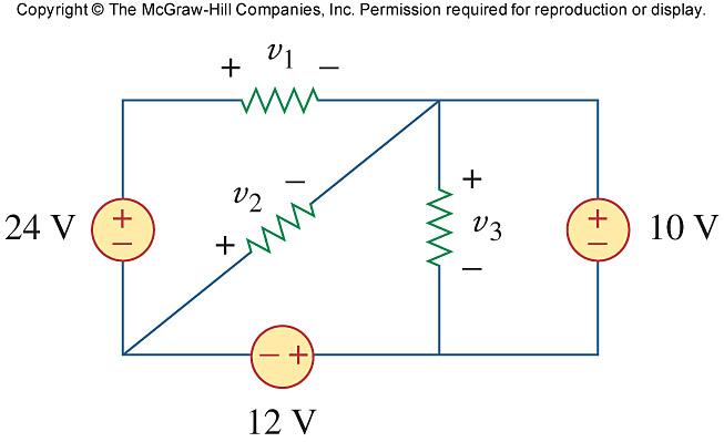 Figure 2.81 For Prob. 2.17.
Solution 2.18
Find I and V in the circuit of Fig. 2.82.
For Prob. 2.18.
Solution.
Step 1. We can make use of both Kirchhoff’s KVL and KCL. KVL tells us that the voltage across all the elements of this circuit is the same in every case. Ohm’s Law tells us that the current in each resistor is equal to V/R. Finally we can use KCL to find I.
Applying KCL and summing all the current flowing out of the top node and setting it to zero we get, –3 + [V/20] + [V/10] + 4 + [V/20] – [–2] = 0.
Finally at the node to the left of I we can write the following node equation which will give us I, –3 + [V/20] + [V/10] + I = 0.
Copyright © 2017 McGraw-Hill Education. All rights reserved. No reproduction or distribution without the prior written consent of McGraw-Hill Education.
Figure 2.82Solution 2.19
Applying KVL around the loop, we obtain
–(–8) – 12 + 10 + 3i = 0 i = –2A
Power dissipated by the resistor:
p Ω 3 = i2R = 4(3) = 12W
Power supplied by the sources:
p 12V = 12 ((–2)) = –24W
p 10V = 10 (–(–2)) = 20W
p 8V = (–8)(–2) = 16W
Copyright © 2017 McGraw-Hill Education. All rights reserved. No reproduction or distribution without the prior written consent of McGraw-Hill Education.
Solution 2.20
Determine i o in the circuit of Fig. 2.84.
Solution Applying KVL around the loop,
+ 22i o + 5i o = 0 i o = 4A
Copyright © 2017 McGraw-Hill Education. All rights reserved. No reproduction or distribution without the prior written consent of McGraw-Hill Education.
Figure 2.84 For Prob. 2.20Solution 2.21
Applying KVL, -15 + (1+5+2)I + 2 V x = 0
But V x = 5I, -15 +8I + 10I =0, I = 5/6
V x = 5I = 25/6 = 4.167 V
Copyright © 2017 McGraw-Hill Education. All rights reserved. No reproduction or distribution without the prior written consent of McGraw-Hill Education.
Solution 2.22
Find V o in the circuit in Fig. 2.86 and the power absorbed by the dependent source.
Solution
At the node, KCL requires that [–V o /10]+[–25]+[–2V o ] = 0 or 2.1V o = –25
or V o = –11.905 V
The current through the controlled source is i = 2V 0 = –23.81 A and the voltage across it is V 1 = (10+10) i 0 (where i 0 = –V 0 /10) = 20(11.905/10) = 23.81 V.
Hence, p dependent source = V 1 (–i) = 23.81x(–(–23.81)) = 566.9 W
Checking, (25–23.81)2(10+10) + (23.81)(–25) + 566.9 = 28.322 – 595.2 + 566.9 = 0.022 which is equal zero since we are using four places of accuracy!
Copyright © 2017 McGraw-Hill Education. All rights reserved. No reproduction or distribution without the prior written consent of McGraw-Hill Education.
Figure 2.86 For Prob. 2.22Solution 2.23
In the circuit shown in Fig. 2.87, determine v x and the power absorbed by the 60-Ω resistor.
Step 1. Although we could directly use Kirchhoff’s current law to solve this, it will be easier if we reduce the circuit first.
The reduced circuit looks like this,
R 1 = 40x60/(40+60)
R 2 = 6 + R 1
R 3 = 15x30/(15+30)
R 4 = 20+R 3
R 5 = R 2 R 4 /(R 2 +R 4 )
Letting V 10 = v x + V R5 and using Kirchhoff’s current law, we get
60 + V 10 /10 + V 10 /(5+R 5 ) = 0
60 + V 10 /10 + V 10 /20 = 0
V 10 = –60x20/3 = –400 volts
Copyright © 2017 McGraw-Hill Education. All rights reserved. No reproduction or distribution without the prior written consent of McGraw-Hill Education.
Figure 2.87 For Prob. 2.23.We could have also used current division to find the current through the 5 Ω resistor, however, i 5 = V 10 /(5+R 5 ) and v x = 5i 5
Calculating the power delivered to the 60-ohm resistor requires that we find the voltage across the resistor. V R5 = V 10 – v x ; using voltage division we get V 60 = [V R5 /(6+R 1 )]R 1 . Finally P 60 = (V 60 )2/60.
Step 2.
R 1 = 40x60/(40+60) = 2400/100 = 24;
R 2 = 6 + R 1 = 6+24 = 30;
R 3 = 15x30/(15+30) 450/45 = 10;
R 4 = 20+R 3 = 20+10 = 30;
R 5 = R 2 R 4 /(R 2 +R 4 ) = 30x30/(30+30) = 15.
Now, we have 60 + (V 10 /10) + (V 10 /(20)) = 0 or V 10 = –60x20/3 = –400 and i 10 = –400/20 = –20 and v x = 5i 5 = 5(–20) = –100 volts
V R5 = V 10 – v x = –400 – (–100) = –300; using voltage division we get V 60 = [V R5 /(6+R 1 )]R 1 . = [–300/30]24 = –240. Finally,
P 60 = (V 60 )2/60 = (–240)2/60 = 960 watts
Copyright © 2017 McGraw-Hill Education. All rights reserved. No reproduction or distribution without the prior written consent of McGraw-Hill Education.
Solution 2.25
V 0 = 5 x 10-3 x 10 x 103 = 50V
Using current division,
Copyright © 2017 McGraw-Hill Education. All rights reserved. No reproduction or distribution without the prior written consent of McGraw-Hill Education.
Solution 2.26
For the circuit in Fig. 2.90, i o = 5 A. Calculate i x and the total power absorbed by the entire circuit.
Solution
Step 1. V 40 = 40i o and we can combine the four resistors in parallel to find the equivalent resistance and we get (1/R eq ) = (1/20) + (1/10) + (1/5) + (1/40).
This leads to i x = V 40 /R eq and P = (i x )2(25+R eq ).
Step 2. V 40 = 40x5 = 200 volts and (1/R eq ) = (1/20) + (1/10) + (1/5) + (1/40) = 0.05 + 0.1 + 0.2 + 0.025 = 0.375 or R eq = 2.667 Ω and i x = 200/R eq = 75 amps.
P = (75)2(25+2.667) = 155.62 kW
Copyright © 2017 McGraw-Hill Education. All rights reserved. No reproduction or distribution without the prior written consent of McGraw-Hill Education.
Figure 2.90 For Prob. 2.26.Solution 2.27
Calculate I o in the circuit of Fig. 2.91.
2.27.
Solution
The 3-ohm resistor is in parallel with the c-ohm resistor and can be replaced by a [(3x6)/(3+6)] = 2-ohm resistor. Therefore,
I o = 10/(8+2) = 1 A.
Copyright © 2017 McGraw-Hill Education. All rights reserved. No reproduction or distribution without the prior written consent of McGraw-Hill Education.
Figure 2.91 For Prob.Solution 2.28
Design a problem, using Fig. 2.92, to help other students better understand series and parallel circuits.
Although there is no correct way to work this problem, this is an example based on the same kind of problem asked in the third edition.
Problem
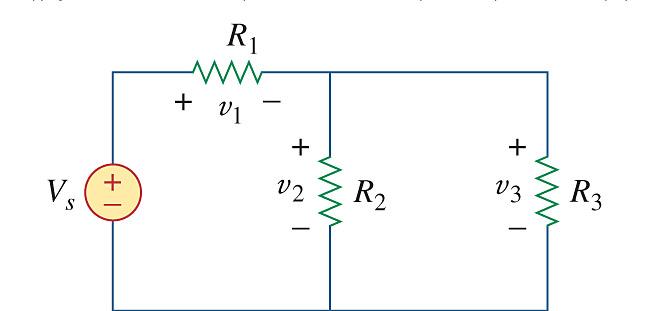
Find v 1 , v 2 , and v 3 in the circuit in Fig. 2.92
Solution
We first combine the two resistors in parallel = 10 15 6 Ω
We now apply voltage division,
v 1 = = + 40) ( 6 14 14 28 V
v 2 = v 3 = = + 40) ( 6 14 6 12 V
Hence, v 1 = 28 V, v 2 = 12 V, v s = 12 V
Copyright © 2017 McGraw-Hill Education. All rights reserved. No reproduction or distribution without the prior written consent of McGraw-Hill Education.
Solution 2.29
All resistors (R) in Fig. 2.93 are 10 Ω each. Find R eq
Solution
Step 1. All we need to do is to combine all the resistors in series and in parallel.
which can be derived by inspection. We will look at a simpler approach after we get the answer.
Copyright © 2017 McGraw-Hill Education. All rights reserved. No reproduction or distribution without the prior written consent of McGraw-Hill Education.
Figure 2.93 For Prob. 2.29.Solution 2.30
Find R eq for the circuit in Fig. 2.94.
Solution
We start by combining the 180-ohm resistor with the 60-ohm resistor which in turn is in parallel with the 60-ohm resistor or = [60(180+60)/(60+180+60)] = 48.
Thus, R eq = 25+48 = 73 Ω
Copyright © 2017 McGraw-Hill Education. All rights reserved. No reproduction or distribution without the prior written consent of McGraw-Hill Education.
Figure 2.94 For Prob. 2.30.Solution 2.32
Find i 1 through i 4 in the circuit in Fig. 2.96.
Solution
We first combine resistors in parallel.
Copyright © 2017 McGraw-Hill Education. All rights reserved. No reproduction or distribution without the prior written consent of McGraw-Hill Education.
Figure 2.96 For Prob. 2.32.Solution 2.33
Combining the conductance leads to the equivalent circuit below
Copyright © 2017 McGraw-Hill Education. All rights reserved. No reproduction or distribution without the prior written consent of McGraw-Hill Education.
Solution 2.34
Using series/parallel resistance combination, find the equivalent resistance seen by the source in the circuit of Fig. 2.98. Find the overall absorbed power by the resistor network.
Step 1. Let R 1 = 400(150+200+50)/(400+150+200+50) and R 2 = 400(70+R 1 +130)/(400+70+R 1 +130). Thus, the resistance seen by the source is equal to R eq = 50+R 2 and total power delivered to the circuit = (600)2/R eq .
Step 2. R 1 = 400x400/800 = 200 and R 2 = 400x400/800 = 200 and R eq = 50+200 = 250 Ω.
Copyright © 2017 McGraw-Hill Education. All rights reserved. No reproduction or distribution without the prior written consent of McGraw-Hill Education.
Figure 2.98 For Prob. 2.34.Solution 2.36
20//(30+50) = 16, 24 + 16 = 40, 60//20 = 15
R eq = 80+(15+25)40 = 80+20 = 100 Ω
i = 20/100 = 0.2 A
If i 1 is the current through the 24-Ω resistor and i o is the current through the 50-Ω resistor, using current division gives
i 1 = [40/(40+40)]0.2 = 0.1 and i o = [20/(20+80)]0.1 = 0.02 A or
v o = 30i o = 30x0.02 = 600 mV.
Copyright © 2017 McGraw-Hill Education. All rights reserved. No reproduction or distribution without the prior written consent of McGraw-Hill Education.
Solution 2.37
Given the circuit in Fig. 2.101 and that the resistance, R eq , looking into the circuit from the left is equal to 100 Ω, determine the value of R 1 .
R1
R1 R1 R1
Step 1. First we calculate R eq in terms of R 1 . Then we set R eq to 100 ohms and solve for R 1
Step 2. 100 = R 1 (3+2)/3 or R 1 = 60 Ω
Copyright © 2017 McGraw-Hill Education. All rights reserved. No reproduction or distribution without the prior written consent of McGraw-Hill Education.
Figure 2.101 For Prob. 2.37.Solution 2.38
20//80 = 80x20/100 = 16, 6//12 = 6x12/18 = 4 The circuit is reduced to that shown below.
(4 + 16)//60 = 20x60/80 = 15
R eq = 2.5+15||15 = 2.5+7.5 = 10
= 35/10 =
and
Copyright © 2017 McGraw-Hill Education. All rights reserved. No reproduction or distribution without the prior written consent of McGraw-Hill Education.
Solution 2.39
Evaluate R eq looking into each set of terminals for each of the circuits shown in Fig. 2.103.
Step 1. We need to remember that two resistors are in parallel if they are connected together at both the top and bottom and two resistors are connected in series if they are connected only at one end with nothing else connected at that point. With that in mind we can calculate each of the equivalent resistances.
Copyright © 2017 McGraw-Hill Education. All rights reserved. No reproduction or distribution without the prior written consent of McGraw-Hill Education.
Figure 2.103 For Prob. 2.39.Solution 2.41
Let R 0 = combination of three 12Ω resistors in parallel
Copyright © 2017 McGraw-Hill Education. All rights reserved. No reproduction or distribution without the prior written consent of McGraw-Hill Education.