Shop Manual CEBM000601 SGD114E=i SAID114E=l SAAGD114E=i SERIES ENGINE SERIAL NUMBERS 45241940andw This material is proprietary to Komatsu America International Company and is not to be reproduced, used, or disclosed except in accordance with written authorization from Komatsu America International Company.
is our policy to improve our products whenever it is possible and practical to do so. We reserve the right to make changes or add improvements at any time without incurring any obligation to install such changes on products sold previously.
to this continuous program of research and development, periodic revisions may be made to this publication. It is recommended that customers contact their distributor for information on the latest revision. May 1997 Copyright 1997 Komatsu America International Company
Engine S6d114e 1 Workshop Manuals
download: http://manualplace.com/download/komatsu-engine-s6d114e-1-workshop-manuals/ This is the cut pages sample. Download all 975 page(s) at: ManualPlace.com
It
Due
Komatsu
Full
SHOP MANUAL ....................................... 01 TROUBLESHOOTING
.................... 02
CONTENTS
& REPAIR MANUAL
VARIOUS PRODUCT PARTS & SERVICE PUBLICATIONS ARE AVAILABLE TO ALL KOMATSU CONSTRUCTION EQUIPMENT OWNERS, INCLUDING OPERATION AND MAINTENANCE MANUALS, PARTS BOOKS AND SERVICE MANUALS. SPECIAL PUBLICATIONS SUCH AS SERVICE TOOL, AIR CONDITIONING, AND TURBOCHARGER SERVICE MANUALS ARE ALSO AVAIlABLE AS WELL AS SELECTED OPERATION & SERVICE MANUALS IN FOREIGN LANGUAGES. THE PUBLICATION LISTED BELOW ARE AVAILABLE FOR THE 6D114E-1 SERIES ENGINE. DESCRIPTION FORM NUMBER SHOP MANUAL SET: CEBM000601 Troubleshooting & Repair Manual PARTS AND SERVICE PUBLICATIONS CAN ONLYBEACQUIRED BY AUTHORIZED KOMATSU DISTRIBUTORS, USING THE KOMATSU PARTS INVENTORY PROCESSING SYSTEM (PIPS). IF THE PIPS SYSTEM IS NOT AVAILABLE AT THE DISTRIBUTOR LOCATION, THEN THE FOLLOWING REQUISITION FOR TECHNICAL SERVICE PUBLICATIONS AND SERVICE FORMS CAN BE USED. FORM KDC91D IS SHOWN ON THE REVERSE SIDE OF THIS PAGE. PUBINFO.KOM 021596
PRODUCT PUBLICATIONS INFORMATION
440 North Fairway Drive
Vernon Hills, IL 60061-8112 U.S.A. Am: Technical Publications Fax No. (847) 970-4186 Tel No. (847) 970-5887
REQUISITION FOR TECHNICAL SERVICE PUBLlCATlONS AND SERVICE FORMS COMPLETE FORM AND RETURN TO -
Komatsu America International Company
COMPANY NAME SHIP TOATTN. TYPE or PRINT STREET ADDRESS ORDER DATE ONLY . . CITY, STATE, ZIP CODE COUNTRY PHONE NO. FAX NO. SHIPPING METHOD DISTR/BRANCH CODE IMPORTANT - TO ASSURE SHIPMENT OF THE CORRECT PUBLICATION(S), THE MODEL NUMBER AND MACHINE SERIAL NUMBER MUST BE SHOWN. QN. PUBLICATION FORM NUMBER PARTS ;FaFe; PUBLICATION DESCRIPTION MODEL NUMBER SERIAL NUMBER g M-Microfiche KDC91 D 022597 CURRENT PRICES WILL BE CHARGED
Shop Manual S6D114E-1 SAGDI 14E-1 SAAGDI 14E-1 Series Engine 6D114E-I Series Engine
Foreword
This manual contains complete rebuild specifications and information for the 6D114E-1 Series engines.
The repair procedures in this manual are based on the engine being installed on an approved engine stand. Some rebuild procedures require the use of special service tools. Make sure the correct tools are used as described in the procedures.
When a specific brand name, number, or special tool is referenced in this manual, an equivalent product can be used in place of the recommended item.
A series of specific service manuals (Shop, Specification, Alternative Repair, and so forth) are available and can be ordered through your distributor using the form in the front of this book.
The specifications and rebuild information in this manual is based on the information in effect at the time of printing. Komatsu America International Company reserves the right to make any changes at any time without obligation. If differences are found between your engine and the information in this manual, contact your Komatsu Distributor.
The latest technology and the highest quality components are used to manufacture Komatsu engines. When replacement parts are needed, we recommend using only genuine Komatsu exchange parts.
‘GROUP 16 02
Engine - Exploded View by Groups GROUP GROUP b9
Engine Identification E
Engine Disassembly and Assembly - Group 00 0
Cylinder Block - Group 01 1
Group
Rocker Levers - Group 03 ..................................... 3
Cam Followers - Group 04 4
Fuel System - Group 05 5
Injectors and Fuel Lines - Group 06 6
Lubricating Oil System - Group 07
Cooling System - Group 08 Drive Units - Group 09 ..............
Air Intake System - Group 10 .........
7 8 9 10
Exhaust System - Group 11 11
Air Equipment - Group 12 12
Electrical Equipment - Group 13 13
Engine Testing - Group 14 14 Instruments and Controls - Group 15 15 Mounting Adaptations - Group 16 16 Specifications and Torque Values - Group 18 18
Page
Table of Contents
Introduction 1
Cylinder Head -
02 . . . . . . . . . . . . . . . . . 2
Index X
i-2 i-8 i-8 i-8 i-7 i-6 i-4 i-9 i-3 i-3 i-3 i-3 i-3 i-5
Section i - Introduction Page i-l
Section
Page
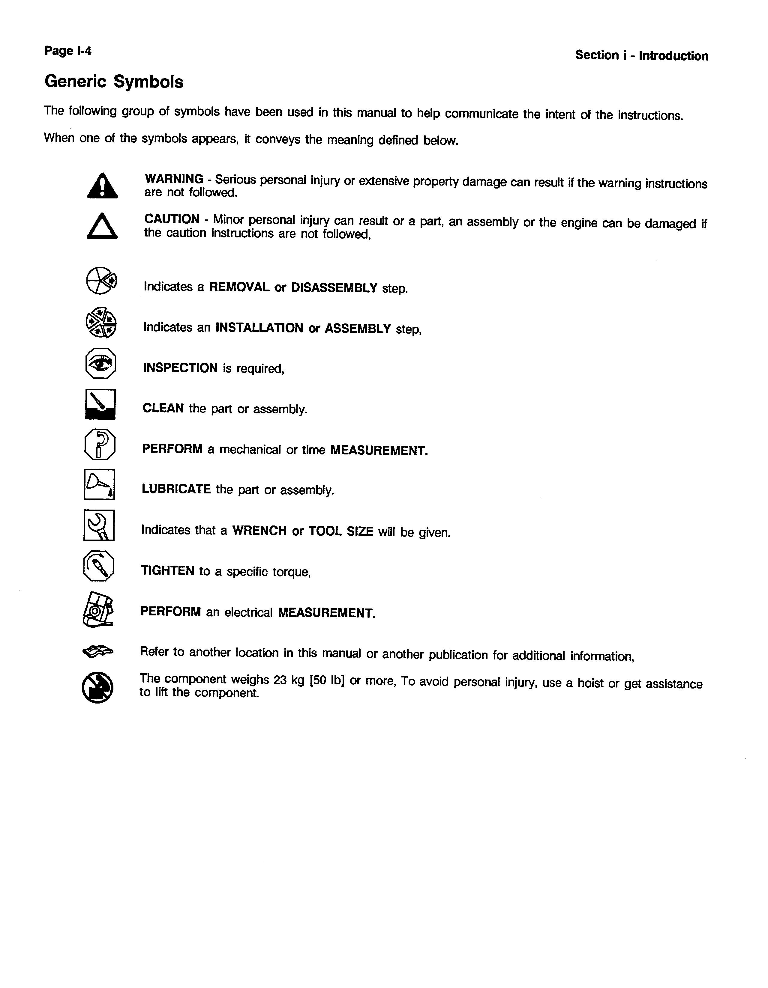
Manual .......................................................... General Cleaning instructions Solvent and Acid Cleaning Steam Cleaning General Repair Instructions General Safety Instructions Generic Symbols Glossary of Terms How To Use This Manual Group Contents Index Metric Information, Table of Contents Illustrations ....................................................
Section i - Introduction
Contents
Aboutthe
About the Manual
This 6D114E-1 Series Shop Manual is intended to aid mechanics in disassembly, inspecting parts for reuse, rebuilding and assembly of components of the 6D114E-1 Series engines. The manual is divided into sections. Section 00 outlines the disassembly and assembly of the engine while the other section detail specific components.
The procedures in this manual were developed for a shop environment with engine disassembly and assembly being performed on a rollover stand. A Group System has been used to subdivide the instructions by major components and systems. Referto the Table of Contents (page i-l) for the various groups. The information is presented in very basic terms to make sure the instructions are easily understood. Wrench sizes and shop tooling are identified in the procedure when needed.
Each group contains the following in sequence:
l An Alphabetical Table of Contents (Index).
l Exploded view(s) of all the components -in the group.
l General Information Section(s) containing the basic service, maintenance, and design information necessary to assist in the rebuild of the engine or a component.
l Procedural instructions for the disassembly, inspection, repair, and assembly that can be required to rebuild an engine. Additional repairs that are not essential during every rebuild, but can be necessary, are included. These repairs depend on the length of time an engine has been in service and the condition of the parts.
Page i-2 Section i - Introduction
How To Use This Manual
Table of Contents
The Table of Contents in the front of the manual contains a quick page reference for each group number.
Group Contents
Each group contains the following information:
l A group index page at the beginning of each group to quickly aid in locating the information desired.
l General information to aid in rebuilding the component and an explanation of design change differences.
l Step-by-step rebuild instructions for disassembly, cleaning, inspection, and assembly of the component.
l Symbols which represent the action outlined in the instructions. The definitions of the symbols, appear on pages i-5 through i-8.
Index
An alphabetical index is in the back of the manual to aid in locating specific information.
Metric Information,
Both metric and U.S. customary values,are used in this manual. The metric value is listed first, followed by the U.S. customary in brackets. An example is 60°C [14O”F].
Section i - Introduction Page i-3
Illustrations
The illustrations used in the “Repair Sections” of this manual are intended to give an example of a problem, and to show what to look for and where the problem can be found. Some of the illustrations are “generic” and might not look exactly like the engine or parts used in your application. The illustrations can contain symbols to indicate an action required, and an acceptable or not acceptable condition.
The illustrations are intended to show repair or replacement procedures. The illustration can differ from your application, but the procedure given will be the same.
Section i - Introduction Page i-5
0+B / ca9OOsh kn9cswt
Important Safety Notice
General Safety Instructions
A WARNING A
Improper practices or carelessness can cause burns, cuts, mutilation, asphyxiation or other bodily injury or death.
Read and understand all of the safety precautions and warnings before performing any repair. This list contains the general safety precautions that must be followed to provide personal safety. Special safety precautions are included in the procedures when they apply.
Make sure the work area surrounding the product is safe. Be aware of hazardous conditions that can exist.
Always wear protective glasses and protective shoes when working.
Do not wear loose-fitting or torn clothing. Remove all jewelry when working.
Disconnect the battery and discharge any capacitors before beginning any repair work. Disconnect the air starting motor if equipped to prevent accidental engine starting. Put a “Do Not Operate” tag in the operator’s compartment or on the controls.
Use ONLY the proper engine barring techniques for manually rotating the engine. Do not attempt to rotate the engine by pulling or prying on the fan. This practice can cause serious personal injury, property damage, or damage to the fan blade(s) causing premature fan failure.
If an engine has been operating and the coolant is hot, allow the engine to cool before you slowly loosen the filler cap and relieve the pressure from the cooling system.
Do not work on any thing that is supported ONLY by lifting jacks or a hoist. Always use blocks or proper stands to support the product before performing any service work.
Relieve all pressure in the air, oil, and the cooling systems before any lines, fiiings, or related items are removed or disconnected. Be alert for possible pressure when disconnecting any device from a system that utilizes pressure, Do not check for pressure leaks with your hand. High pressure oil or fuel can cause personal injury.
To prevent suffocation and frostbite, wear protective clothing and ONLY disconnect liquid refrigerant (freon) lines in a well ventilated area. To protect the environment, liquid refrigerant systems must be properly emptied and filled using equipment that prevents the release of refrigerant gas (fluorocarbons) into the atmosphere. Federal law requires capture and recycling refrigerant.
To avoid personal injury, use a hoist or get assistance when lifting components that weigh 23 kg [50 lb] or more. Make sure all lifting devices such as chains, hooks, or slings are in good condition and are of the correct capacity. Make sure hooks are positioned correctly. Always use a spreader bar when necessary. The lifting hooks must not be side-loaded.
Corrosion inhibitor contains alkali. Do not get the substance in your eyes. Avoid prolonged or repeated contact with skin. Do not swallow internally. In case of contact, immediately wash skin with soap and water. In case of contact, immediately flood eyes with large amounts of water for a minimum of 15 minutes. IMMEDIATELY CALL A PHYSICIAN. KEEP OUT OF REACH OF CHILDREN.
Naptha and Methyl Ethyl Ketone (MEK) are flammable materials and must be used with caution. Follow the manufacturer’s instructions to provide complete safety when using these materials. KEEP OUT OF REACH OF CHILDREN.
To avoid burns, be alert for hot parts on products that have just been turned OFF, and hot fluids in lines, tubes and compartments.
Always use tools that are in good condition, Make sure you understand how to use them before performing any service work. Use ONLY genuine replacement parts.
Always use the same fastener part number (or equivalent) when replacing fasteners, Do not use a fastener, of lessor quality if replacements are necessary.
Do not perform any repair when fatigued or after consuming alcohol or drugs that can impair your functioning.
Page i-6
Section i - introduction
General Repair Instructions
This engine incorporates the latest diesel technology; yet, it is designed to be repaired using normal repair practices performed to quality standards.
Komatsu America International Company does not recommend or authorize any modifications or repairs to engines or components except for those detailed in Komatsu Service Information. In particular, unauthorized repair to safety-related components can cause personal injury. Below is a partial listing of components classified as safety-related:
Air Compressor
Air Controls
Air Shutoff Assemblies
Balance Weights
Cooling Fan
Fan Hub Assembly
Fan Mounting Bracket(s)
Fan Mounting Capscrews
Fan Hub Spindle
Flywheel
Flywheel Crankshaft Adapter
Flywheel Mounting Capscrews
Fuel Shutoff Assemblies
Fuel Supply Tubes
Lifting Brackets
Throttle Controls
Turbocharger Compressor Casing
Turbocharger Oil Drain tine(s)
Turbocharger Oil Supply Line(s)
Turbocharger Turbine Casing
Vibration Damper Mounting Capscrews
Follow All Safety Instructions Noted In the Procedures.
Follow the manufacturer’s recommendations for cleaning solvents and there substances used during the repair of the engine. Some solvents and used engine oil have been identified by government agencies as toxic or carcinogenic. Avoid excessive breathing, ingestion and contact with such substances. Always use good safety practices with tools and equipment.
Provide A Clean Environment and Follow the Cleaning Instructions Specified in the Procedures
The engine and its components must be kept clean during any repair. Contamination of the engine and components will cause premature wear.
Perform the Inspections Specified in the Procedures.
Use Genuine Komatsu Service Parts and Assemblies
Replace all Components or Assemblies Which are Damaged or Worn Beyond the Specifications
- The assembly instructions have been written to use again as many components and assemblies as possible. When it is necessary to replace a component or assembly, the procedure is based on the use of new Komatsu components. All of the repair services described in this manual are available from all Komatsu Distributors.
0 Follow The Specified Disassembly and Assembly Procedures to Avoid Damage to the Components.
Complete rebuild instructions are available in the shop manual which can be ordered or purchased from your Komatsu Distributor. Refer to Section L, Literature, for ordering instructions.
Section i - Introduction Page i-7
General Cleaning Instructions
Solventand Acid Cleaning
Several solvent and acid-type cleaners can be used to clean the engine parts. Komatsu America International Company does not recommend any specific cleaners. Always follow the cleaner manufacturer’s instructions.
Experience has shown that the best results can be obtained using a cleaner that can be heated to 90 to 95” Celsius 1160to 200” Fahrenheit]. A cleaning tank that provides a constant mixing and filtering of the cleaning solution will give the best results.
Remove all the gasket material, o-rings, and the deposits of sludge, carbon, etc., with a wire brush or scraper before putting the parts in a cleaning tank. Be careful not to damage any gasket surfaces. When possible, steam clean the parts before putting them in the cleaning tank.
Warning: The use of acid can be extremely dangerous to personnel and can damage the machinery. Always provide a tank of strong soda water as a neutralizing agent.
Rinse all of the parts in hot water after cleaning. Dry completely with compressed air. Blow the rinse water from all of the capscrew holes and the oil drillings.
If the parts are not to be used immediately after cleaning, dip them in a suitable rust-proofing compound. The rustproofing compound must be removed from the parts before installation on the engine.
Steam Cleaning
Steam cleaning can be used to remove all types of dirt that can contaminate the cleaning tank. It is a good way to clean the oil drillings.
Warning: Wear protective clothing to prevent personal Injury from the high pressure and extreme heat. Do not steam clean the following parts:
Glass or Plastic Bead Cleaning
Glass or plastic bead cleaning can be used on many engine components to remove carbon deposits. The cleaning process is controlled by the size of the glass or plastic beads, the operating pressure, and the cleaning time.
Caution: Do not use glass or plastic bead cleaning on aluminum piston skirts. Do not use glass bead cleaning on aluminum ring grooves. Small particles of glass or plastic will embed in the aluminum and result in premature wear. Valves, turbocharger shafts, etc. can also be damaged. follow the cleaning directions listed in the procedures.
Follow the equipment manufacturer’s cleaning instructions. The following guidelines can be used to adapt to manufacture’s instruction:
1. Bead size: Use U.S. size No. 60 for general purpose cleaning with glass media.
2. Operating Pressure: Glass: Use 620 Kpa 190psi] for general purpose cleaning.
3. Steam clean or wash the parts with solvent to remove all of the foreign material and glass or plastic beads after cleaning. Rinse with hot water. Dry with compressed air.
4. Do not contaminate the wash tanks with glass or plastic beads.
Page i-8 Section i - Introduction
1. Electrical
2. Wiring 3. Injectors 4. Fuel Pump 5. Belts and Hoses 6. Bearings
Components
A. C.:
Glossary of Terms
Definition Alternating Current
AFC: Air Fuel Control; a device in the fuel pump that limits the fuel delivery until there is sufficient intake manifold pressure to allow for complete combustion.
ATDC: After Top Dead Center; refers to the position of the piston or the crankshaft rod journal. The piston is moving downward on the power stroke or intake stroke.
BDC: Bottom Dead Center; refers to the position of the piston or the crankshaft rod journal. The piston is at its lowest position in the cylinder.
BTDC: Before Top Dead Center; refers to the position of the piston or the crankshaft rod journal. The piston is moving upward on the compression stroke or exhaust stroke.
Circumferential Direction: In the direction of a circle in respect to the centerline of a round part or a bore.
Concentricity: A measurement of the difference between the centers of either two or more parts or the bores In one part.
Silicone Sealant: This is a one part Room Temperature Vulcanizing (RTV) silicone rubber, adhesive and sealant material having high heat and oil resistance, and low compression set.
Some of the equivalent products are Marston Lubricants, Hylosil, Dow Corning, Silastic 732, Loctite Supetflex, General Electric RTV108and Three Bond Sealant.
D. C.:
Direct Current
Dye Penetrant Method: A method used to check for cracks in a part by using a dye penetrant and a developer. Use crack detection kit, Part No. 3375432, or its equivalent.
End Clearance: The clearance in an assembly determined by pushing the shaft in an axial direction one way and then pushing the shaft the other way.
E. S. N.
Engine Serial Number
Hammer: A hand tool consisting of a hard steel head on a handle.
I.
D.:
Loctite 290:
Inside Diameter
A single component, anaerobic, polyester resin, liquid sealant compound that hardens between closely fitted metal surfaces producing a tough. hard bond. Equivalent products are Komatsu 1232 273 Hl and Perma-Lok HL 126.
Loctite 609: A single component anaerobic, liquid adhesive that meets or exceeds the requirements of MIL-R-46082A (MN) TYPEl.
Some of the equivalent products are Komatsu 634 018 Cl, Loctite 601 and Permabond HL 138.
Lubriplate 105: A mineral oil base grease with calcium soap (2 percent to 6 percent), and zinc oxide (2 percent to 4 percent) additives.
Magnetic Particle Inspection: A method of checking for cracks in either steel or iron parts. This method requires a Magnaflux or equivalent machine that imparts a magnetic field on the part being checked.
Mallet: A hand tool consisting of a sofi head, either wood, plastic, lead, brass, or rawhide, on a handle.
Section i - Introduction
Page i-9
MAX:
MIN: No.: O.D.:
OS: Protrusion:
STD:
TC: TDC: T.I.R.:
Water Pump Grease:
Definition
Maximum allowed
Minimum allowed Number
Outside Diameter
Oversize
The difference in the height between two parts in the assembled state.
Standard
Torque Converter; used when referring to the torque converter cooler.
Top Dead Center; refers to the position of the piston or the crankshaft rod journal. The piston is at its highest position in the cylinder. The rod journal is pointing straight up toward the piston.
Total Indicator Runout; used when measuring the concentricity or the runout. The T.I.R. refers to the total movement of the needle on a dial indicator, from the most negative reading to the most positive reading.
A premium high temperature grease that will lubricate anti-friction bearings continually from minus 40” C [minus 40” F] to plus 150” C [plus 350” F]. Some of the greases meeting this requirement are Aeroshell No. 5, Chevron SRI, Amoco Rykon Premium No. 2, Texaco Premium RB, and Shell Dolium R. Aeroshell No. 5 is not compatible with the other greases and must not be mixed. Aeroshell No. 5 is used on new engines and components.
Page i-10 Section i - introduction
Section E - Engine and Component Identification
Section Contents
Engine Diagrams 6
Engine Identification ......................................................... 2 Engine Dataplate 2 Fuel Injection Pump Dataplate 3
General Engine Specifications 4 Cooling System
5 Fuel System 5 General Engine Data 4 Intake Air and Exhaust System 5 Lubrication System.. 4
Section E - Enaine and Component Identification Page E-l
Page
............................................................
6Cl
Engine Identification
Engine Dataplates
The engine dataplates show specific information about your engine. The engine serial number provides information for ordering parts and service needs.
The engine dataplates are located on the front gear cover housing, on the fuel pump side of the engine, oriented 90 degrees from horizontal. See drawing at left.
NOTE: The engine dataplate must not be changed unless approved by Komatsu.
Engine Identification Page E-2 Section E - Engine and Component Identification
KOMATSU C.I.D/L CPL EUXN -!3ERIAL ND. FAMILY Lmo.Lruhcr., Illcmr.,6W69 U.S.A. TIMING EC %a? + + KCMATSU PART No. Vo,-ntnp,In vc, Y., R..ult And Y.rron~ I* -e Vo1d.d If bu.1 Rar. Rpy 0, Allrrudm cxemd VALVE LASH COLD INT. Em. PubLImhsd km,.“. Vm1u.s For Tht. Med.1 And nRING RAE0 l+vKw AT m Appr LODI twl. “md&!!.A. LOU IDLE RANGE FUEL RATE AT RATED IP MM3/STROKE GCTAG
Engine Dataplates The. Komatsu model designation represent the basrc desrgn and confrguratron of your engine. (1) Turbocharged Example Engine Model Name: (2) Jacket water aftercooled (JWAC) 6D114E-1, S6D114E-1, SAGD114E-1 or SAAGD114E-1 (2) or (3) (3) Charged air cooled (CAC) S A (AA) 6 D114 E -1 (4) Number of cylinders (1) (2) (3) (4) (8) (6) (7) (8) (5) Diesel (6) Cylinder Bore Dia. in mm (7) Emission&d (8) Engine Series Komatsu Engine S6d114e 1 Workshop Manuals Full download: http://manualplace.com/download/komatsu-engine-s6d114e-1-workshop-manuals/ This is the cut pages sample. Download all 975 page(s) at: ManualPlace.com
1

