MARK ERLER / M.Arch
RECENT PROFESSIONAL WORK
MARK ERLER / M.Arch
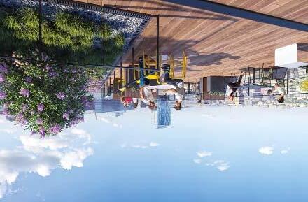
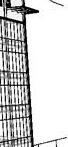
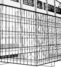
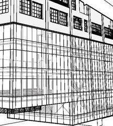
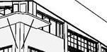
ALOHA SUBSTATION
Project Scope: Adaptive reuse of existing concrete warehouse into open office and retail. New steel frame and glass curtain wall facade supported by the original concrete structure below. Addition of exposed super-x seismic braced frames for lateral support.
Role: Project Architect
Lead construction administration, developed construction documents, MUP and permit documents. Modeled with ArchiCad. Graphics using ArchiCad and Illustrator. Renderings by others.
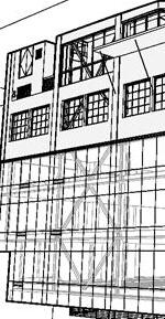
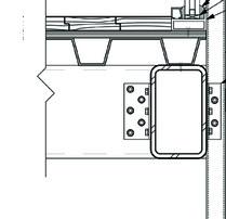
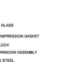
2"3'-6" SLOPE TYPICAL PARAPET @ CURTAIN WALL MTL CAP FLASHING PER MFR SPANDREL GLASS BACKPAN PER SSG JOINT PER CURTAIN WALL MFR ALIGN R3: PENTHOUSE ROOF PENETRATION BOOT OR PMMA STL TUBE PER STRUCT STL BASE PLATE PER STRUCT 1/2" CONC. OVER 1 1/2" ST/ DECK STL TUBE PER STRUCT 1/2" 1/2" ST PLATE BOTTOM FRAME 1/2 1/2 ST. TUBE TO LOWER ST. TUBE (TYP) CONT WOOD CAP FULLY WELD TOP TO PLATE TO ST. TUBE. ELIMINATE WATER PENETRATION INTO TUBE SSG JOINT PER CURTAIN WALL MFR FRAMED WALL BY SILL CONNECTION PER MFR BY FUTURE TENANT SPANDREL GLASS BACKPAN PER CURTAIN WALL MFR INSULATION INT EXT 2"2" CURTAIN WALL ALIGN EXT. F.O. CURTAIN WALL W/ EXT. F.O. (E) CONC. WALL BELOW SHEET METAL FLASHING SHEET METAL FLASHING & CONT. CLEAT 1/4" STEEL PLATE CAULK 5/4" PTD WOOD SILL SELF-ADHERED FLASHING @ ROUGH OPENING WRB (E) PILASTER BEYOND (E) CONC. WALL 1" A531 BACKER ROD @ GYP. BD, TYP. (E) 1" CHAMFER LIQUID FLASHING FROM CONC., INBOARD OF WINDOW FRAME SEALANT/BACKER ROD (COMPATIBLE W/ LIQUID FLASHING) FILL CHAMFER W/ PROSOCO JOINT AND SEAM, COVER WITH LIQUID FLASHING MEMBRANE, TYP. 1" MIN. FROM EDGE OF APPLY INTERIOR SEALANT ON BOTH SIDES OF WINDOW ATTACHMENT STRAPS. WET SET STRAPS AND SEAL OVER TO FULLY ENCAPSULATE. TOPPING SLAB 3RD FLOOR +27'-6 1/2" (E) BUILDING TO REMAIN UNITIZED CURTAINWALL SYSTEM A NEW ADDITION, TYP SOUTH AND EAST ELEVATIONS (N) WINDOWS IN (E) LOCATIONS. WINDOW SILL TO BE LOWERED TO 36" AFF, TYP SECOND FLOOR ROOF DECK (E) CANOPY TO REMAIN (N) STAIR IN RATED ENCLOSURE (N) ELEVATOR IN (N) SHAFT STEEL BRACED FRAMES, SEE STRUCT (N) STOREFRONT IN (E) OPENINGS (N) STAIR EXIT AND BIKE ROOM ENTRY AT GRADE (N) ADA ENTRY TO RETAIL ACCESS TO (N) TRASH ROOM (E)1ST FLOOR SLAB TO REMAIN (E) CONC COLUMNS TO REMAIN
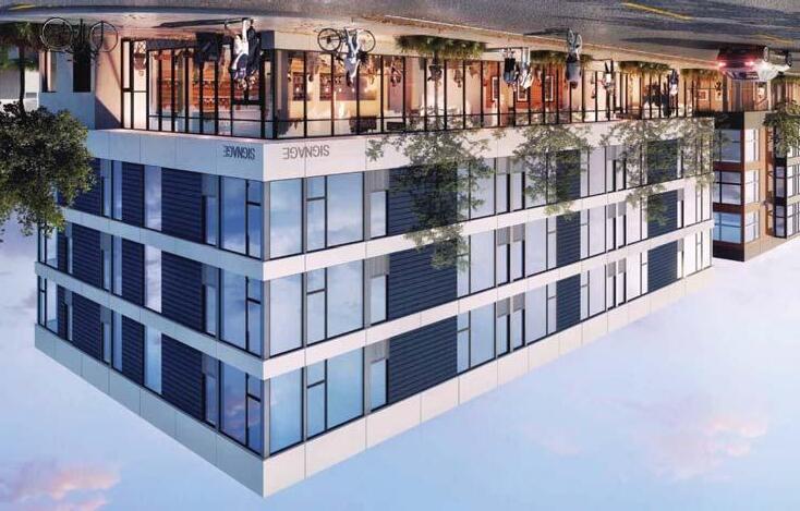
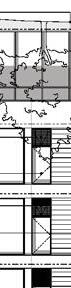
BLOCK 4A
Project Scope: Four-story mixeduse apartment building with 36 residential units. The project includes street-level retail, at-grade parking, landscaped rooftop terrace, amenity spaces and bike room. Type-V over Type-I construction.
Role: Project Architect
Developed construction documents and permit documents. Modeled with ArchiCad. Renderings by others
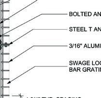
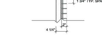
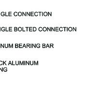
221'-2" 1ST FLR 234'-5" 2ND FLR 244'-3" 3RD FLR 254'-1" 4TH FLR 263'-11" ROOF STRUCTURE 265'-7 1/2" ROOF (PAVERS) 275'-7 1/2" PENTHOUSE 13'-3"9'-10"9'-10"9'-10" 1'-8 1/2" 10'-0" 11'-10" EQ 3'-0"4'-0" 10" (ALIGN WITH DR HDR) 4'-0" RESIDENTIAL ENTRY CEMENT BOARD SOFFIT FP-03 VENT AT NORTH WALL OF BIKE ROOM FIBER CEMENT BOARD, FP-01 FIBER CEMENT BOARD @ FLOOR BANDS, TYP FP-01 FIBER CEMENT BOARD, FP-01 FIXED WDW, TYP VNL-01 CASEMENT WDW VNL-01 SHIPLAP CEMENT BOARD PANELS FP-02 ALUMINUM STOREFRONT AL-01 METAL TRIM MTL-01 AWNING WINDOW TYP VNL-01 JULIET RAILING TYP MTL-02 UNIT VENTING BEHIND FP-01, TYP. 36" H MTL RAILING FIBER CEMENT BOARD, FP-01 MTL WEATHER PROTECTION EXPOSED CONCRETE CONC JOINT, TYP THROUGH WALL FLASHING 223 222 221 18 18 1 1 13 A431 A501 A431 A320 A301 A303 A301 A310 A313 4"3'-1"4" 3'-4"3'-10"51/2" 3'-4" 3"6'-4"1'-61/4"2'-21/2" 3'-31/4"3'-31/4"6"7'-01/4"51/2"10'-33/4" 4'-23/4" 1/2" 1/4" 7'-61/2"4'-2"9'-41/2"2'-10" 1/2" 5/8" 5/8" 4'-11/4"8'-0" 2'-3" 15'-1"21'-7"6'-7"7'-10 1/4"10'-11 3/4"16'-1" 6'-4"6"12'-01/4"6" 61'-2" 6"23'-51/4"6"1" ACCESSCLEANOUT ROUTESTOROOF. P1 P2 D1 D2 L1 L2 FLOORDRAIN,TYP ORIGIN POINT PRIVATE PRIVATE PRIVATE PRIVATE (PANELS CLOSET, 12"DEPTH PER PLANTINGS, PERLA CORRIDOR 220 TRASH/RECYC GRSF:498.01 sq GRSF:369.31 GRSF:498.56 sq DN 14 14 14 14 X21 X21 X21 PROTECTIONREQUIRED LESSTHAN10',TYP ELEV STUDIO TYPE0.10 209 1-BDRM TYPE1.13 204 AFFORDABLEUNIT STUDIO TYPE0.10 STUDIO TYPE0.10 STUDIO TYPE0.10 1-BDRM TYPE1.10 1-BDRM TYPE1.13 212 STUDIO GRSF:406.06 GRSF:369.33 GRSF:485.54 sq GRSF:406.53 GRSF:369.33 sq GRSF:615.61 GRSF:374.15 INSTRUCTIONS SEE 5/BE-3.2 FOR WATERPROOFING AT THIS LOCATION HEAD FLASH HT SAM MANUFACTURER'S INSTRUCTIONS CLR 1/2" OPNG FOR FRESH AIR UNIT BEYOND OPNG FOR FRESH AIR UNIT PORT FRAMING, SSD FP-01 PAINTED CEMENT BOARD PANEL ON ALUM BAR GRATE RAIL, ATTACHED VIA ALUM L-ANGLES NOTES
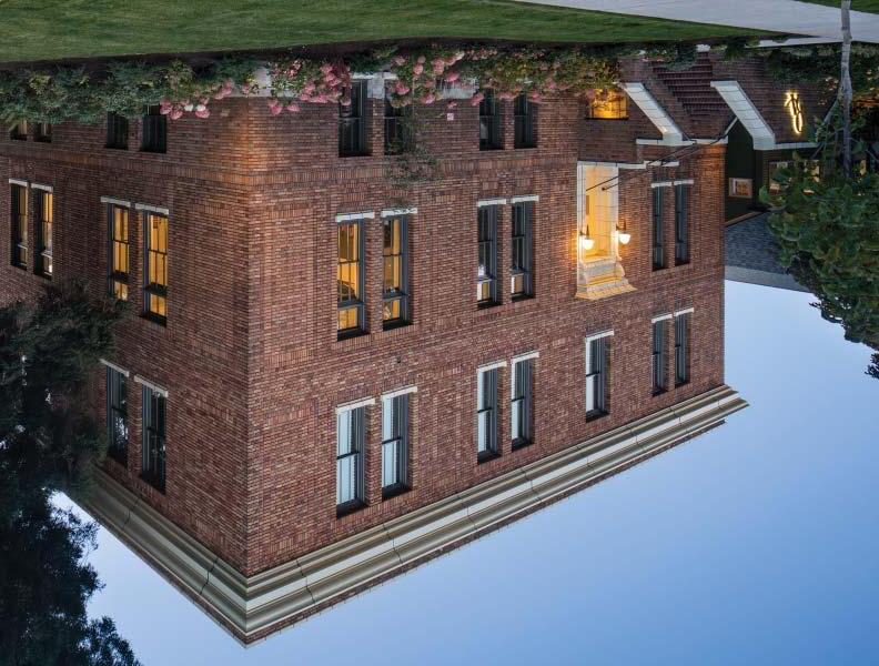
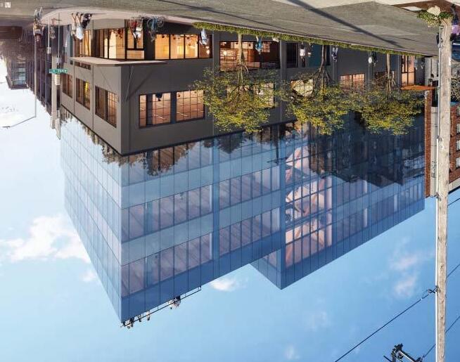
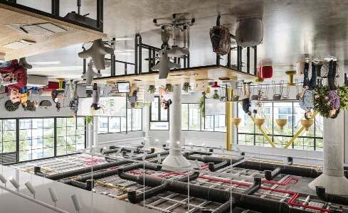
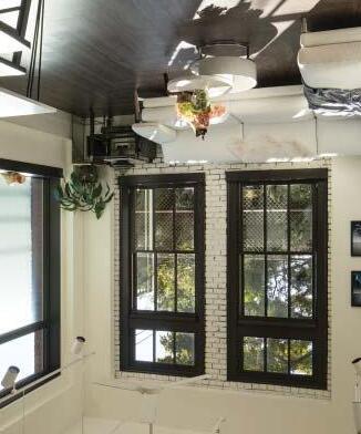
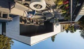
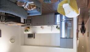
QUEEN ANNE EXCHANGE
Project Scope: Conversion of Seattle Landmark building into 25 loft-style apartments with new penthouse addition. Seismic upgrades, facade restoration, new exterior windows and below-grade parking.
Role: Project Architect Lead construction administration and development of permit documents. Developed unit concepts and layouts in collaboration with Graham Baba. Photos by others.
STUDENT WORK
MARK ERLER / M.Arch
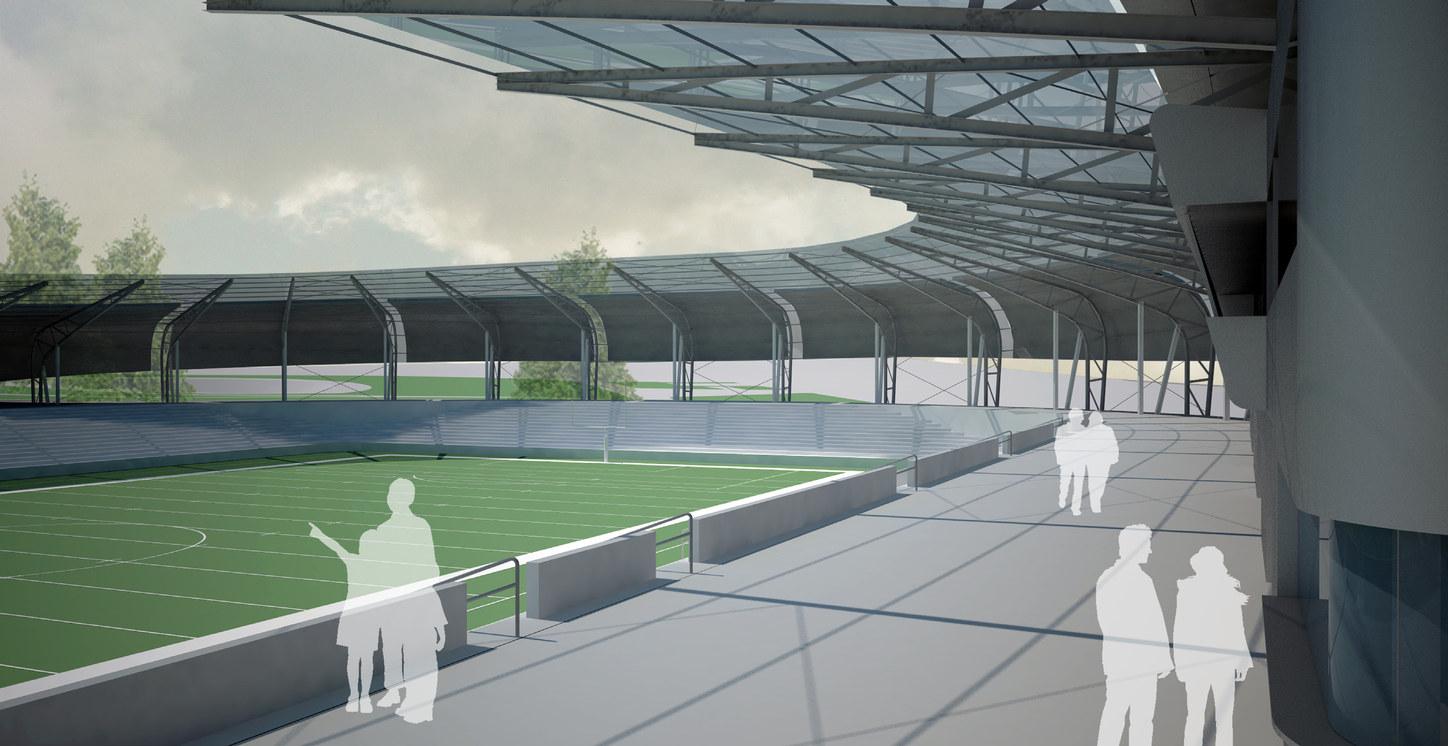
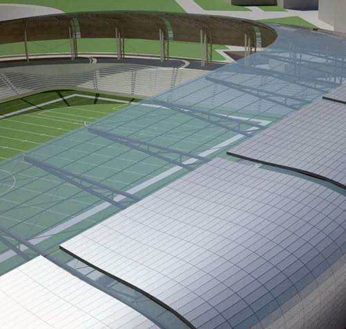
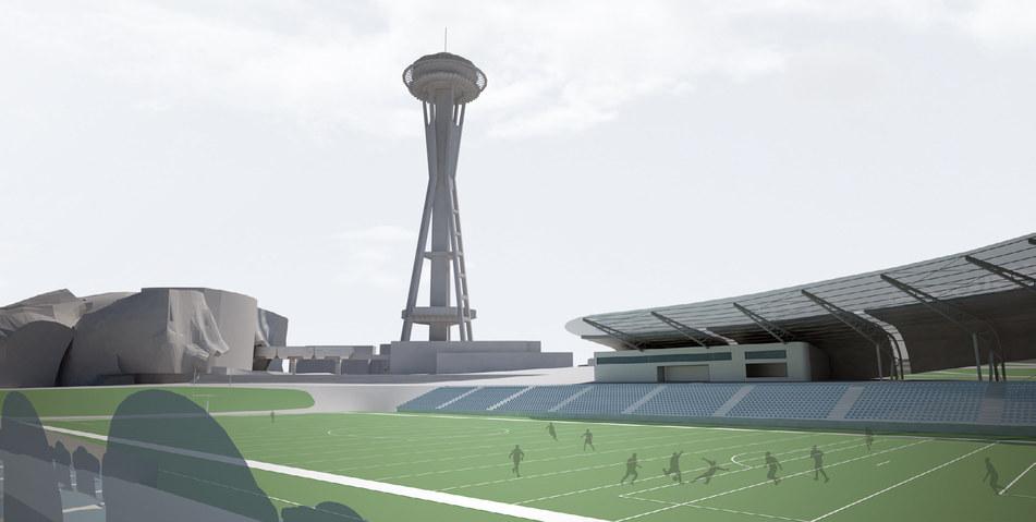
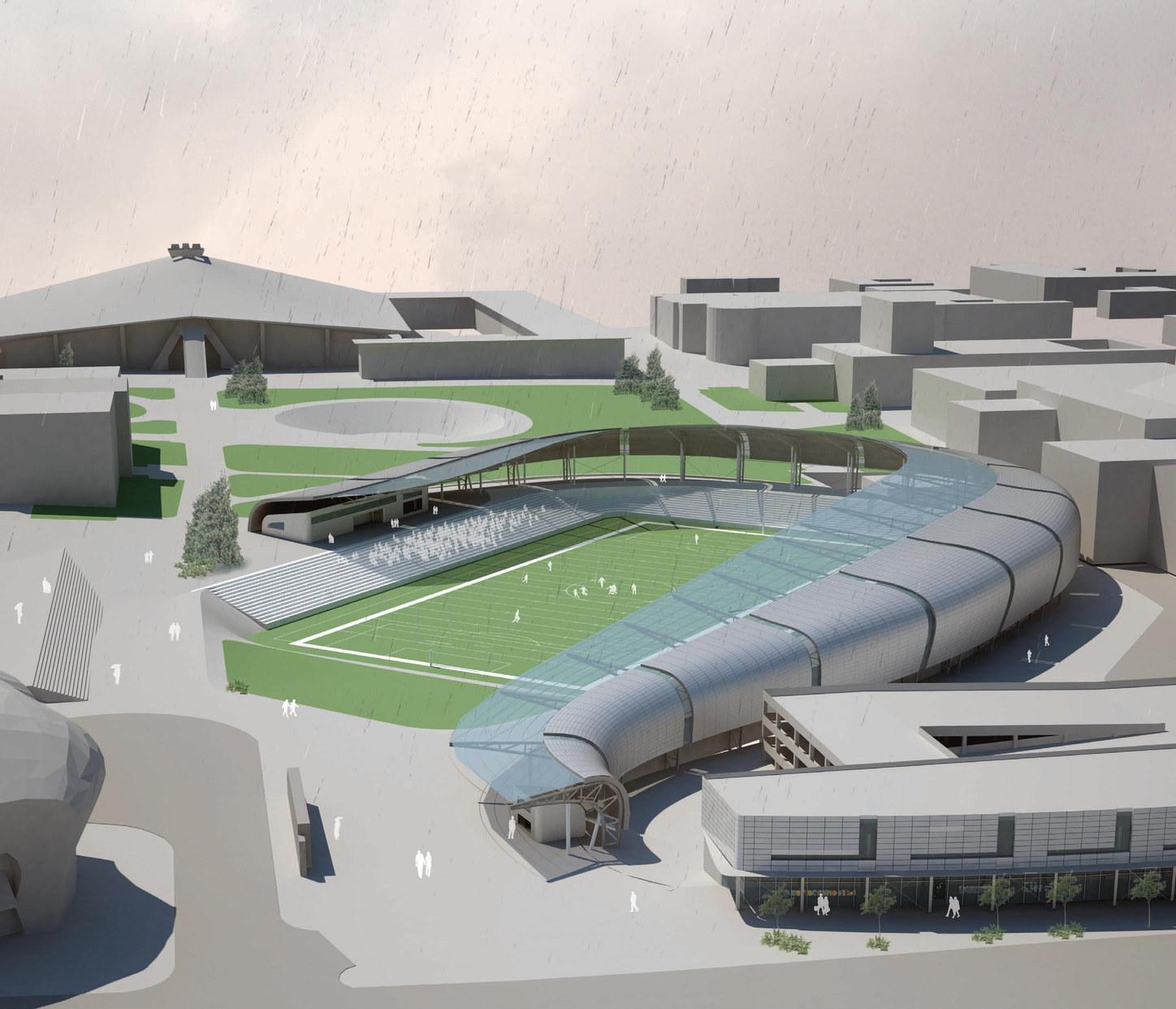
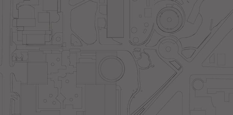
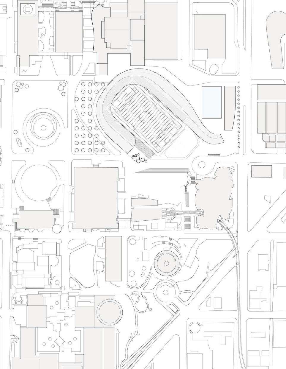
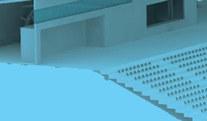
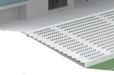
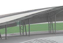
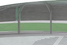
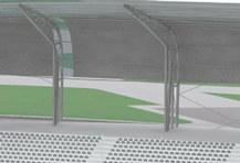
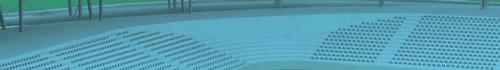
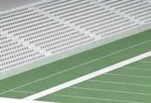
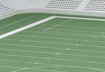
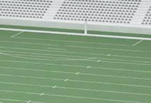
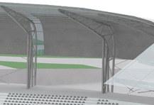
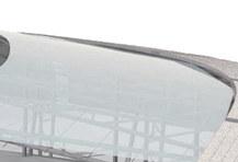
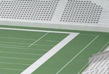
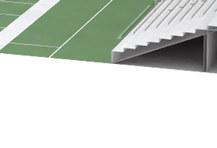
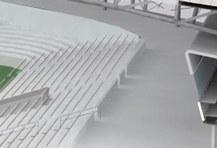
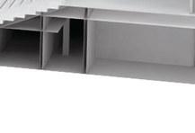
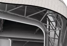
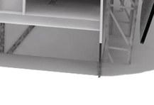
MEMORIAL STADIUM 2012
new proposal for Seattle’s Memorial Stadium at Seattle Center. The project takes an urban design approach to create a more open facility that connects people, spaces and the varied programmatic elements of the Seattle Center campus. The design meets the requirements of the city’s Century 21 Masterplan and serves as a counterpoint to modern American stadium planning and design.
A
Professor Sarah Lorenzen Spring 2011 ARC 695
1
Player Entrance: Back of house entry for players & participants with direct eld access
2 Parking: Multilevel parking structure provides access for both participants and visitors
3 O ce Space: Expands the carrying capacity of Seattle Center, allowing more cultural groups to take root on campus while creating an activated street presence and promoting foot tra c
4 Ticket Booth
5 Viewing Lawn: The south end park provides an alternate viewing experience and room for spillover during summer concerts when the venue experiences peak attendance levels
6 Memorial Wall: The historic wall is preserved and relocated to a prominent entry point with increased visibility
7 Terraced Steps: Creates an elevated view onto the eld and visually connects the venue to this major courtyard space. The wide steps provide increased permeability and a casual space to sit, socialize and enjoy the campus

Concessions
Restrooms


Field is reoriented to lie within the acceptable solar range for football and soccer.
N
FOOTBALL&SOCCER
48° 1 2 3 5 6 4 7


Locker Rooms
Restrooms
Media Box Level


PUBLICPLAYER BOH EMP Monorail Space Needle
and
Player amenities located on lower level providing private entry/dropo point
direct eld access.
Player Access
Concourse level access for spectators
Evolution of stadium shape through analysis of pedestrian tra c patterns Open sightlines to major landmarks Activate street, add space for new cultural organizations Separate functions between public and participants Route and engage pedestrians, visually connect stadium and campus spaces
Public Access
ION HOUSE
Collapsible / Deployable Housing
Arc 602 / Winter 2011 / Professor George Proctor
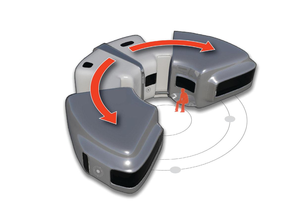
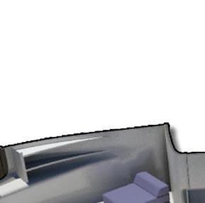
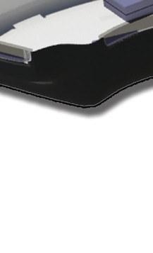
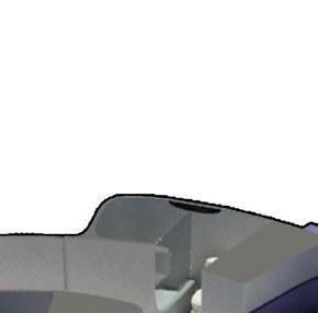
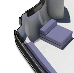
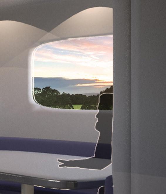
The Ion House explores potentialities for collapsible, expandible, deployable housing. The programmatic requirements allowed a maximum of 500 SF. The Ion House creates and leverages outdoor courtyard space to meet this goal while gaining an additional usable area for residents. The collapsed unit is designed to be transported on a crane-equipped low bed cargo truck and deployed onsite. It features two bedrooms with built-in storage, kitchen, bath, dining table and accomodations for one guest.


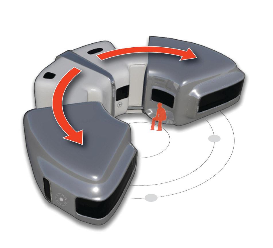

Closed Deployed 2 Adults 2 Children
1 Guest Leverage outdoor space Subdivide interior space Entry at program break points Circulation: Minimal space usage
CONCEPT


Shower
Bathroom
Table/Guest Bed
Kitchen


The outdoor social core creates a focal point for family life while two bedrooms on opposing sides allow for relative privacy. The bedrooms/ ex spaces expand from the center allowing the mechanical core to remain stationary. The kitchen table collapes to create an additional sleeping space for a guest. Animations of the project are available at www.markerler.com.


Chair/Folding Bed


Storage
Bench


 BEDROOM / FLEX SPACE
MECHANICAL CORE
BEDROOM / FLEX SPACE
BEDROOM / FLEX SPACE
MECHANICAL CORE
Proposed circulation Deployed Closed
Increased shell strength and functionality
Circulation:

Bedroom / Flex Space


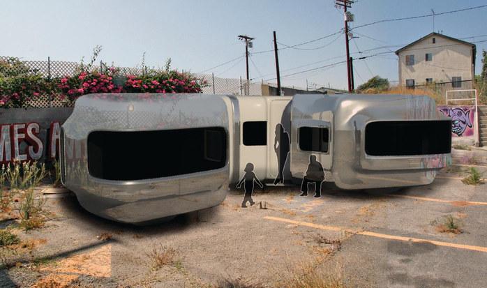
Kitchen Urban Deployment
Kitchen Table
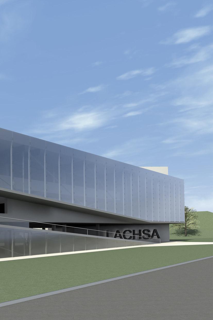
LACHSA
LOS ANGELES COUNTY HIGH SCHOOL FOR THE ARTS
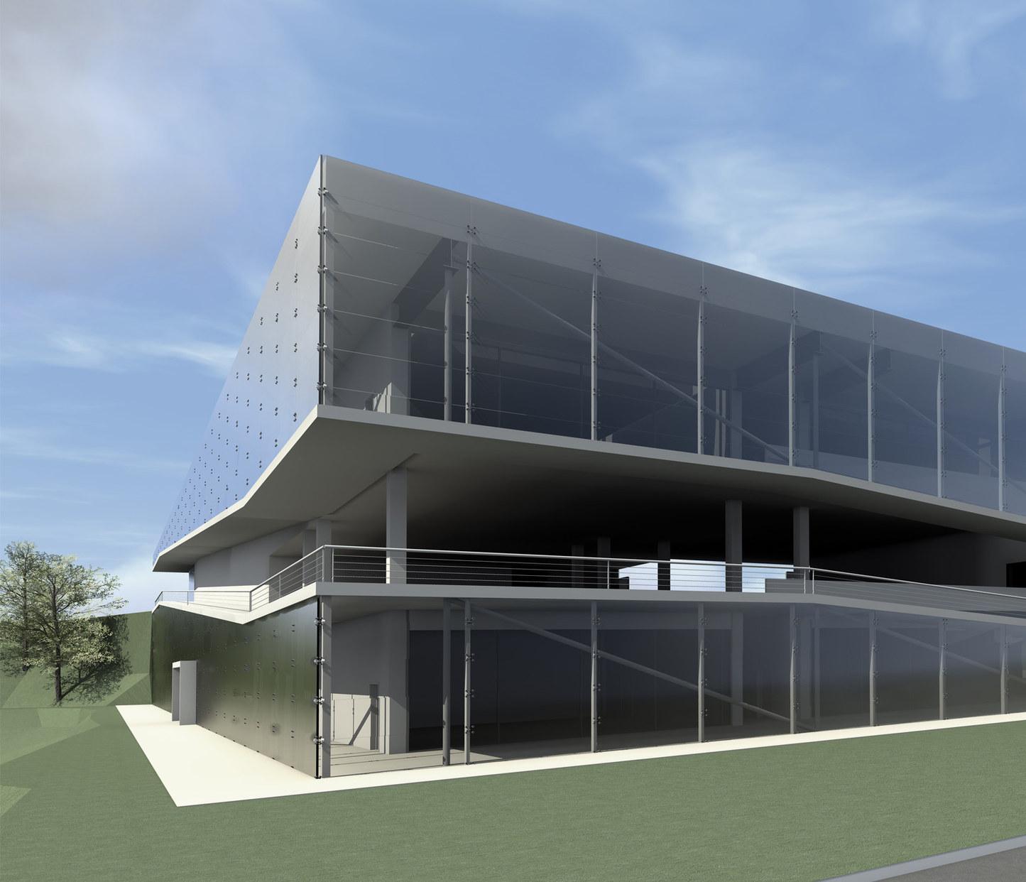
The Los Angeles County High School for the Arts (LACHSA) offers a specialized magnate program combining college prep academic instruction and conservatory-style training in the visual and performing arts. Founded in 1985, the tuitionfree public school is run by the Los Angeles County Office of Education in partnership with and on the campus of California State University, Los Angeles (CSULA).
LACHSA will soon build its own 50,000 SF facility on the CSULA campus. The project will serve over 570 students in four separate arts disciplines. Programmatic requirements include studios, classrooms, offices, gathering spaces, a theater and supporting functions for students and faculty.
ARC 505 | WINTER 2010 | PROFESSOR KIP DICKSON
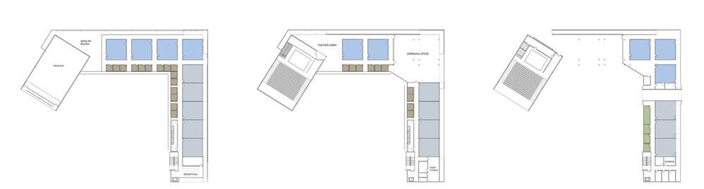
Studios Classrooms Office Custodial 2 3 1
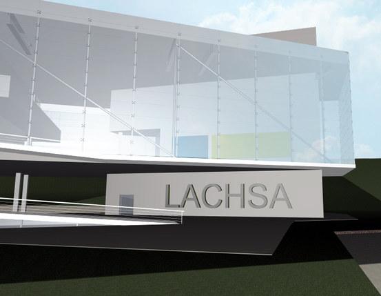
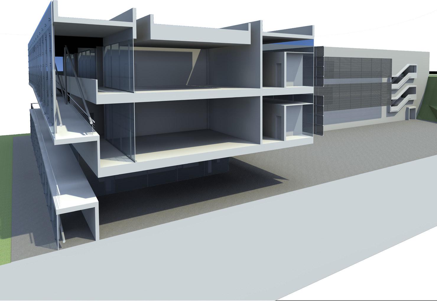
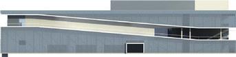
The design creates a dynamic space for interaction and learning. The project takes advantage of sweeping mountain views to the north and east, and an abundance of unobstructed northern light for studio spaces. The 30 ft elevation change is navigated by an exterior ramp that slices the facade and guides users through the building’s main communal space on the second floor. The design takes advantage of the hillside to create an open yet protected courtyard space for students to enjoy, aiming to strike a balance between engaging the greater CSULA campus and creating a safe, nurturing environment for its own students.


 Main Entry Communal Space
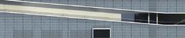
East Elevation
North Elevation
Main Entry Communal Space
East Elevation
North Elevation
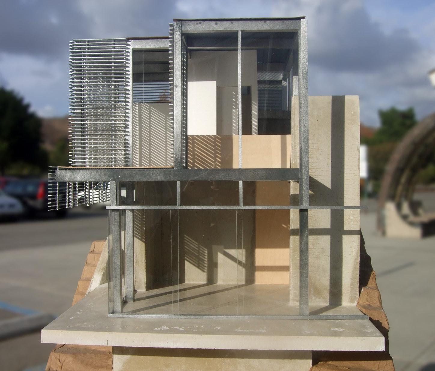
ARC 504 / Professor Judith Sheine
Fall 2009
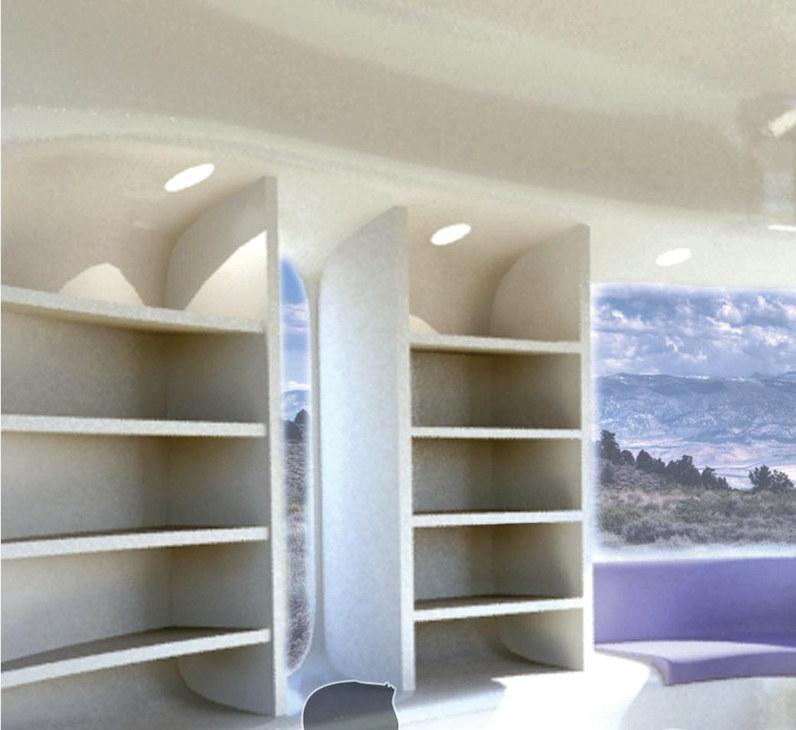
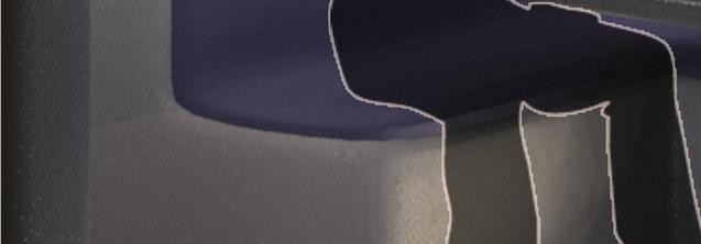
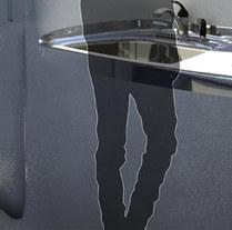
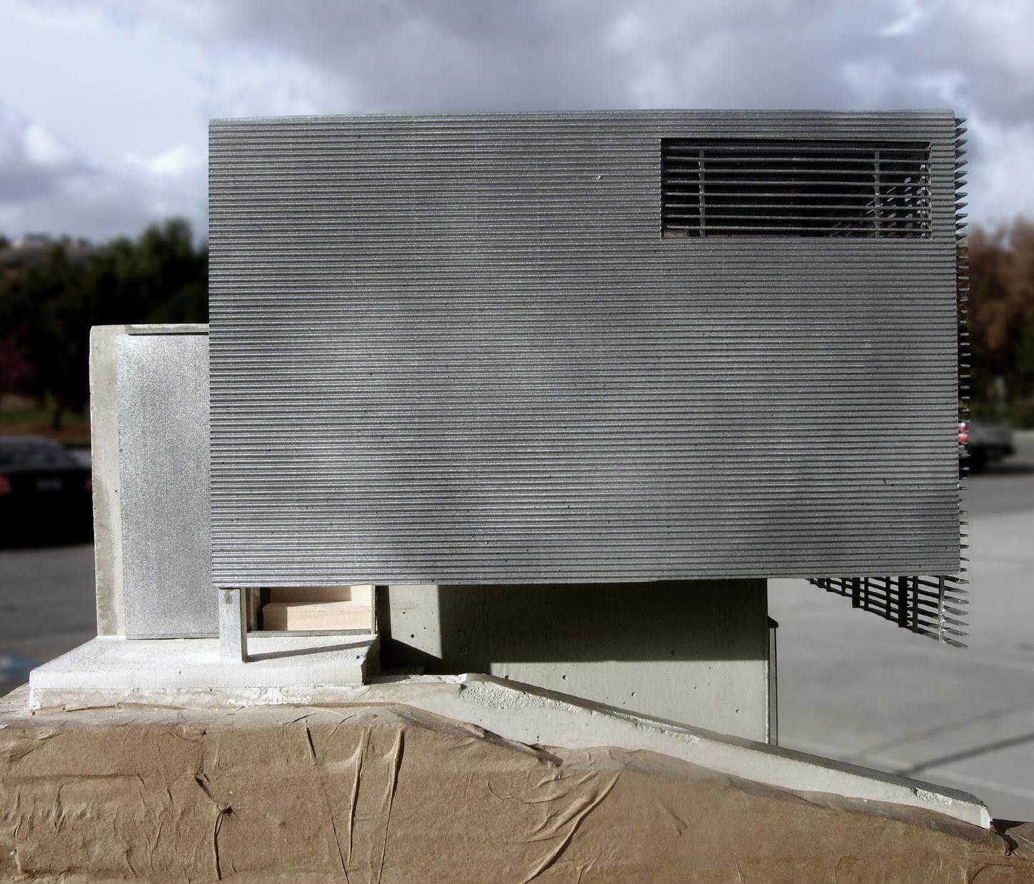
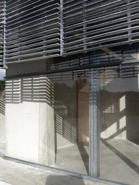
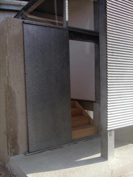
500 SF summer retreat sited near a hillside ravine on Southern California’s Mt. Baldy.
1” = 1’-0” scale model
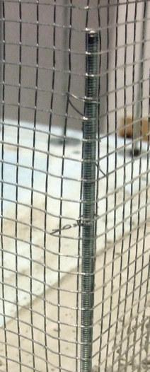
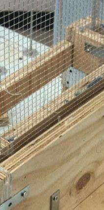
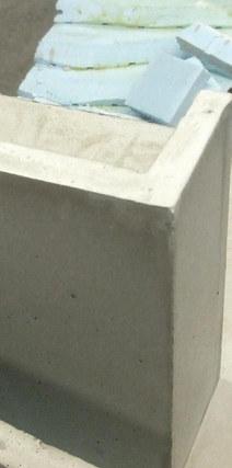
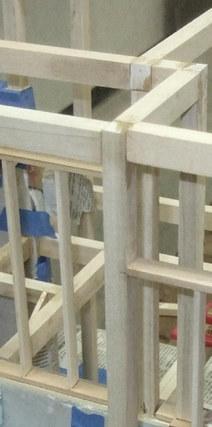
CONSTRUCTION
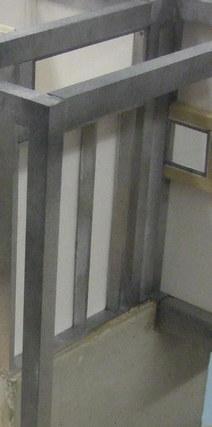
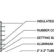
1” = 1’- 0” scale model: welded wire mesh, threaded rod, portland cement, rigid foam, basswood, artboard, spraypaint, cardboard, acrylic, epoxy
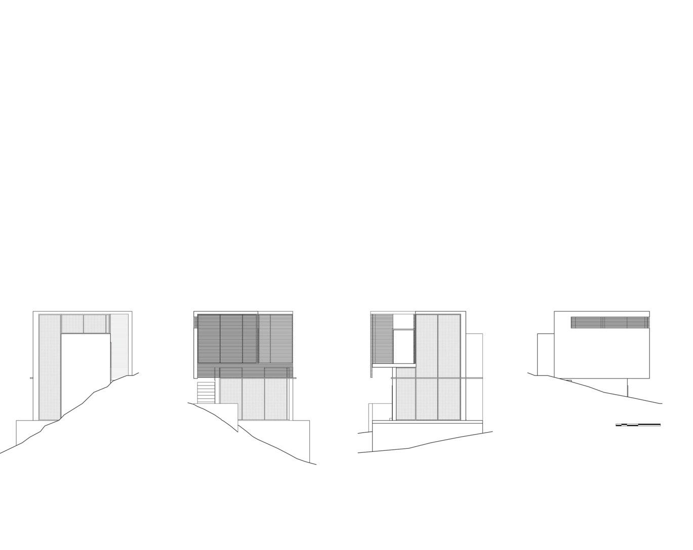
North Elevation
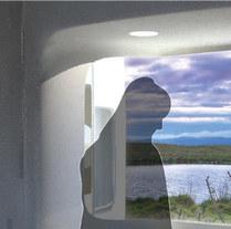
Light well brings light to lower space
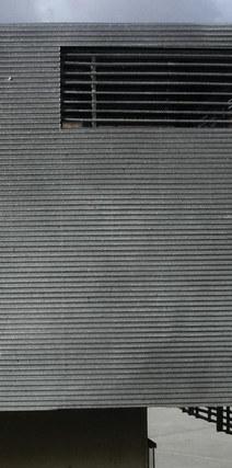
South Elevation
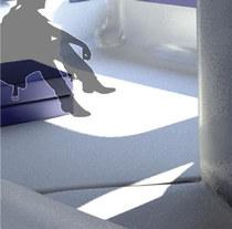
Louvers protect southern exposure, maximize top level square footage and shade lower story
East Elevation
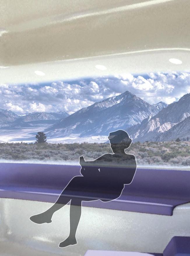
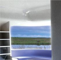
Double height glazing for premier landscape views
West Elevation
Protects western exposure and creates privacy from upper slope
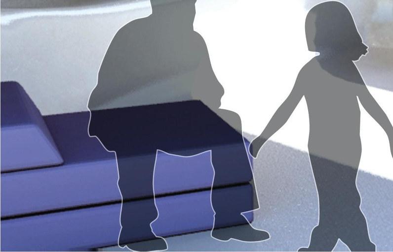
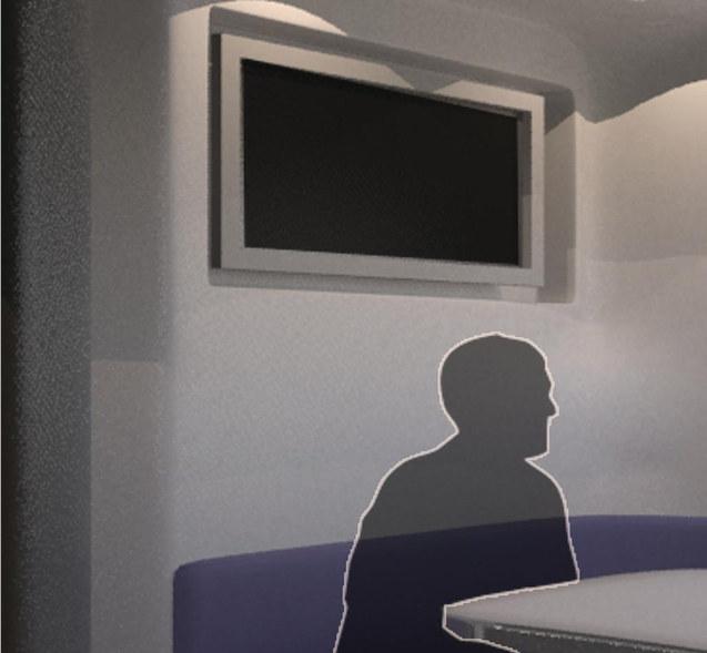
The project called for a 500 SF summer home for a filmmaker on a steep mountain hillside. The design creates a two story space to accomodate the need for both privacy and openness to the surrounding landscape. Geometrically abstracted yet responsive to the environment, each facade deals uniquely with its respective solar orientation and view. The bed and bath are located on the more protected upper level, while the lower level features an open floorplan with sliding glass walls that expand the space and connect inside and out.
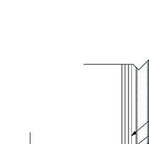
DETAILS


 Bedroom
Living Room
Main Entry
Bedroom
Living Room
Main Entry