
Study and Analysis of Failure Analysis of Wire Rope
Ram Kishore Prasad1, Abdul Razzaque Ansari2, MD. Asif Equbal3, Mukesh Kumar Sahu4
1Cambridge Institute of Technology, Department of Mechanical Engineering, Ranchi, Jharkhand, India

2Cambridge Institute of Technology, Department of Mechanical Engineering, Ranchi, Jharkhand, India
3Cambridge Institute of Technology, Department of Mechanical Engineering, Ranchi, Jharkhand, India
4Cambridge Institute of Technology, Department of Mechanical Engineering, Ranchi, Jharkhand, India ***
Abstract Wire ropes operate at high stress levels and are almost invariably subject to fluctuating loads. The continuous degradation of wire rope affected with operative services will ultimately lead to failure. In this present work the test sample was adopted as the single steel wire. To explore the effects of the load, test on normal wire (steel) and fretting wire (steel) the, breaking tensile tests were carried out for both types of wires samples by using a universal tensile testing (UTM) machine (INSTRON limited high Wycombe, Model No. 8801). This test (Tensile) includes three major stages (elastic deformation, plastic deformation and finally the fracture failure) in the process of breaking tensile.
Key Words: Wire rope failure, wire rope, Wear scar, Tensile test
1. INTRODUCTION
Steel Wire Ropes are frequently used for lifting devices because of their distinctive design.
With numerous working components that cooperate to support or move the load, wire rope might be compared to a sophisticated machine. Everywhere, including but not limited to suspension bridges, towers, elevators, and the lifting and rigging industries, wire ropes are employed.
The wire rope is constructed from multiple steel wires that are twisted together to create distinct threads that form a helical pattern around the centre. The advantages of this structure include its tremendous strength, flexibility, and resistance to bending stresses. Many material and wire combinations have various benefits, such as strength, flexibility, and resistance to corrosion, crushing, and fatigue. Several structural components, including rope, have the ability to withstand relatively large axial loads in comparison to bending and torsional loads [1-3]. Because of this quality, ropes were among the first tools employed by human civilization.

1.1. Main Components of the wire rope
One metallic wire that is very thin makes up the basic part. Figure 1. shows the various components and how the strands are arranged around the central core.
Several materials can be used to create the core. It could be made of polypropylene, wire rope, or natural fibres. A centre wire that acts as the axial component is frequently wrapped helically around many metallic wires. It is important to remember that strands make up the majority of a wire rope's load-bearing parts. The core's function is to give the strands the necessary support under typical bending and loading circumstances.
They are the smallest part that make up each of the distinctive individual strands of the rope. One of the various metallic substances that can be used to manufacture wires is steel. Several types of wires are produced based on their strength and resistance to wear, fatigue, and corrosion. Usually, the wires are either uncoated or have a beautiful polish. The most frequent crosssection for wires is spherical. Nonetheless, profile wires are occasionally used. Profile wires are defined as wires with a cross section different than a spherical section.
Strands
Strands are composed of many wires that have been precisely twisted and arranged. Then, the different strands are arranged in a helical pattern to surround the core. Larger diameter wires provide more abrasion resistance, whilst smaller diameter wires have higher flexibility.
wire rope Lay length and lay angle
In its simplest and most fundamental form, the strand consists of three or four twisted wires, as was the case with Albert's initial wire rope, which had three straightforward strands with four wires each. Today, however, a single layer of wires that are organised helically around a central wire make up the most fundamental strand.
1.2. Wear
One of the main ways steel wire ropes degrade is through wear. The friction between the wires of the rope causes internal wear, and bending the rope over sheaves or drums causes outside wear. The latter is more typical in the vast majority of rope applications. The rope’s safe working life is shortened by the point contacts and excessive wear caused by the bending pressures.
2.LITRATURE REVIEW
Because to the ubiquitous use of wire ropes, various academics have done substantial research on the material's pertinent characteristics over time. In order to assess the tribological characteristics of ropes, Mc Coll et al. [4] examined the impact of low viscosity oils, with and without graphite additions, on the fretting behaviour of a high-strength eutectoid steel rope wire. The surface property of the fretting scar was investigated. In a series of investigations on the fretting wear and fatigue of steel wires,
Zhang et al. [5] investigated the wear depth and the fracture life under contact loads following each fretting friction test.
Cruzado et al. [6–7] planned numerous experimental programme and investigated the effects of these 2elements on the fretting wear behaviour of the thin steel wires for dry friction. This is because the effect of the contact pressure and crossing angle on the wear of the rope wires is highly essential. Forcing fatigue experiments were extensively used by Wang et al. [8–9] to study the failure mechanism of hoisting rope. Under various displacement amplitudes and strain amplitudes, he examined the wear mechanism of the fretting contact scars and fretting fatigue life. The impact of various corrosive fluids on the fretting fatigue damages of mine rope wires was investigated in light of the complex hoisting situations.
Wang et al. [10-11] also investigated the dynamic wear evolution and crack propagation of steel wires under fretting-fatigue. The wear depth and wear scar profiles were quantitatively analysed. Although there are substantial discrepancies between the wear characteristics of wires and ropes, Oksanen et al. [12–13] used studies to better understand the rope's wear by examining the wear mechanisms between the roller and the wire rope. In a previous study, we conducted a number of friction and wear experiments on a home-built test rig and looked at the tribological properties of the winding hoisting ropes in various sliding scenarios [14]
a. Analysis of steel wire rope (unused) with different diameters with 7 mm and its tensile test by using Universal Testing Machine (UTM) and compare its performance and failure analysis.
b. Analysis of steel wire rope with fretting (artificial) with reduced diameters of above stated wire 6 mm via experimental analysis in UTM.
2.1. Experimental based braking failure analysis of steel wire with and without fretting
The test sample was adopted as the single steel wire. The steel wire is made of high-quality carbon structural steel by the process of cold drawing.
The braking failure analysis was performed on the UTM machine made of INSTRON limited high Wycombe, Model No. 8801 (England) which is having maximum capacity of 100 kN.
Steel wire and its fretting have been measured with the help of digital screw gauge.
2.2. The Stress calculation is given as
Here, σ refers to the stress F is the force applied and A denotes the area of the surface. The unit of stress is Pascal or N/m2.
2.3. The Strain calculation is given as Strain = x L
Where, Change in dimension is x, The original dimension is L.
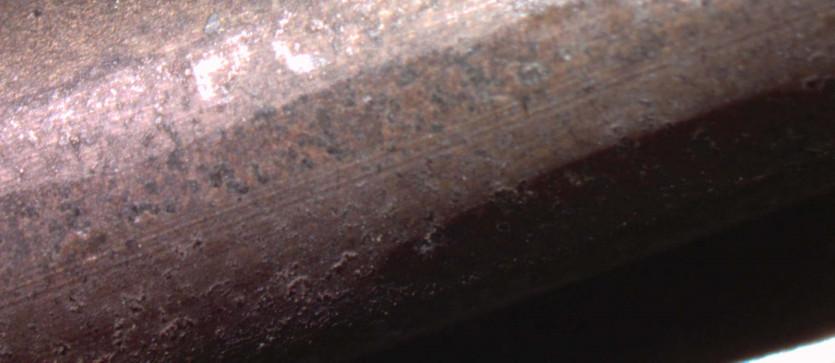
Figures 2 to 3 show the images taken by the optical microscope and the scanning electron microscope (SEM) for the normal steel wire and the fretting wire.
Figures 2 and 3 shows the images of normal steel wire (7 mm) and the fretting wire of the same diameter having the reduced diameter after the fretting is 6 mm.
Figures 4 and 5 shows the stress-strain diagram of steel wire (7 mm) and the fretting wire of 6 mm respectively


In x axis there is strain and in y axis there is stress in MPa.
These graphs are plotted on the basis of experimental works. The main results are shown in the Table 1.
4.SIMULATION BASED ANALYSIS


4.1. Analysis of Steel Wire (7 mm)- without fretting
Fig.6. shows the geometric modelling in ANSYS of solid structure ABAQUS of steel wire similer to the wire which have been used in the experimental analysis i.e. it have lay length of 90 mm and diameter of 7 mm.


Fig.8. shows the deformation on steel wire after application of tensile force which have been simulted by the software.
Fig.6. Geometry modelling of steel wire without fretting (7 mm)
Fig.7. shows the meshing of the steel wire after modelling and selection of material properties it is next step in the analysis.

Fig.8. Deformation of without fretting steel wire (7 mm)
Fig.9. shows the Von Mises stress on steel wire after application of tensile force which have been presented here after simultion by the software.
Fig.9 Von Mises stress on without fretting steel wire (7 mm).
Fig.10. shows the strain on the steel wire after the application of tensile force.
4.2.With Fretting of steel wire (7mm)
Fig.11. shows the geometric modelling in ANSYS of frettiing of steel wire. Frettiing have been taken here at the between of the wire or at the centre length of the wire.


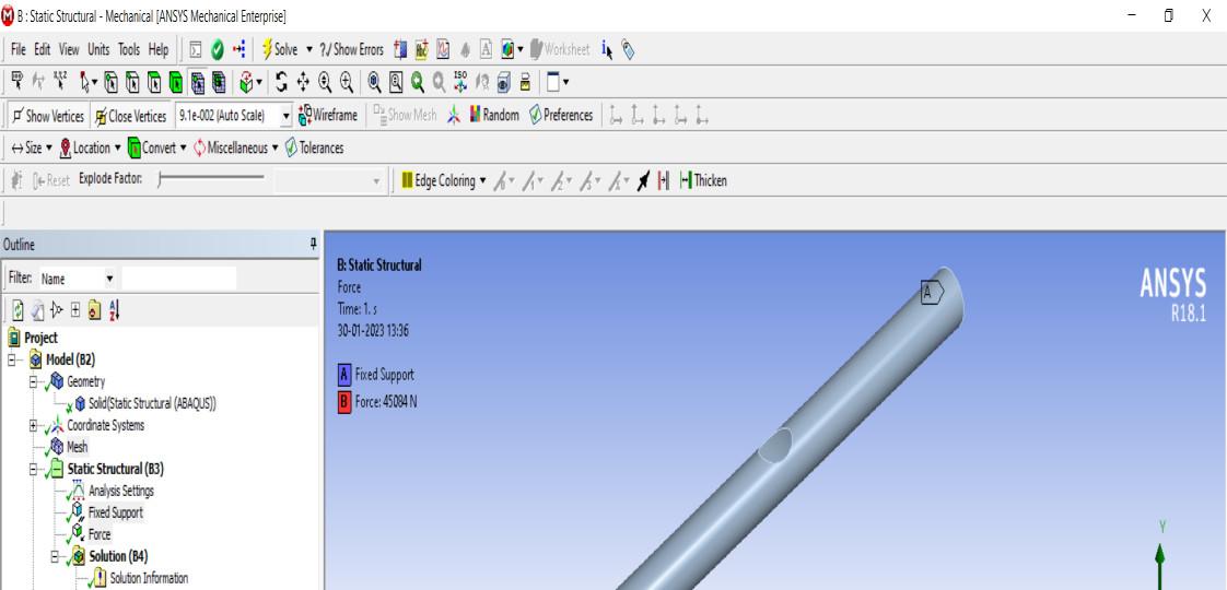


Fig.12. shows the meshing of steel wire with fretting of having 7 mm diameter.
Fig.13. shows the application of force on steel wire with fretting.
Fig. 16. Analysis of Strain on steel wire with fretting (7mm)
Fig.16. shows the simulated result of strain of fretting steel wire having 7 mm diameter.
5. CONCLUSIONS
1. For steel wire having diameter 7 mm without fretting maximum tensile stress ( ) is obtained by experimental results is 1171.50 (MPa) while by the simulation in ANSYS it is obtained as 1109 (MPa).
2. For the wire with fretting (reduced diameter = 6 mm) maximum tensile stress is obtained as 1427.82 (MPa) while by the ANSYS it is obtained as 1485 (MPa).
3. For steel wire having diameter 7 mm without fretting modulus of elasticity (E) is obtained 63289.42 (MPa) by experimental results. For the same wire with fretting (reduced diameter = 6 mm) maximum modulus of elasticity (E) is obtained as 78854.32 (MPa).
So it can be concluded that by the fretting of wire results in higher modulus of elasticity (E).
REFERENCES
[1] Leschen Wire Rope Company, in Wire Rope Handbook, St. Joseph, Mo, 1971.
[2] A. Castello, Theory of wire rope (2nd ed.), Springer Publishing, 1997.
[3] K. Freyer, Wire Ropes: Tension, Endurance, Reliability, Springer , 2007.
[4] McColl IR, Waterhouse RB, Harris SJ, Tsujikawa M. Lubricated fretting wear of a high-strength eutectoid steel rope wire. Wear 1995;185:203–12.
[5] Zhang DK, Ge SR, Qiang YH. Research on the fatigue and fracture behavior due to the fretting wear of steel wire in hoisting rope. Wear 2003;255:1233–7.
[6] Cruzado A, Hartelt M, W€asche R, Urchegui MA, G_omez X. Fretting wear of thin steel wires Part 1: influence of contact pressure. Wear 2010;268:1409–16.
[7] Cruzado A, Hartelt M, W€asche R, Urchegui MA, G_omez X. Fretting wear of thin steel wires Part 2: influence of crossing angle. Wear 2011;273:60–9.
[8] Wang DG, Zhang DK, Ge SR. Effect of displacement amplitude on fretting fatigue behavior of hoisting rope wires in low cycle fatigue. Tribol Int 2012;52:178–89.
[9] Wang DG, Zhang DK, Ge SR. Fretting–fatigue behavior of steel wires in low cycle fatigue. Mater Des 2011;32:4986–93.
[10] Wang DG, Zhang DK, Zhao WJ, Ge SR. Quantitative analyses of fretting fatigue damages of mine rope wires in different corrosive media. Mater Sci Eng A 2014; 596:80–8.
[11] Wang D, Li X, Wang X, et al. Dynamic wear evolution and crack propagation behaviors of steel wires during fretting-fatigue. Tribol Int 2016;101:348–55.
[12] Oksanen V, Andersson P, Valtonen K, Holmberg K, Kuokkala VT. Characterization of the wear of nodular cast iron rollers in contact with wire ropes. Wear 2013;308: 199–205.
[13] Oksanen V, Valtonen K, Andersson P, Vaajoki A, Laukkanen A, Holmberg K, et al. Comparison of laboratory rolling–sliding wear tests with in-service wear of nodular cast iron rollers against wire ropes. Wear 2015;340:73–81.
[14] Chang XD, Peng YX, Zhu ZC, et al. Tribological properties of winding hoisting rope between two layers with different sliding parameters. Adv Mech Eng 2016;8(12):1–14.