Caterpillar C15

Product:TRUCKENGINE
Model:C15TRUCKENGINEMXS
Configuration:C15On-HighwayTruckMXS00001-UP
DisassemblyandAssembly
C15On-highwayEngines
MediaNumber-RENR9403-13PublicationDate-01/11/2017DateUpdated-29/11/2017
FuelPrimingPump-RemoveandInstall
SMCS-1258-010
RemovalProcedure
NOTICE
Caremustbetakentoensurethatfluidsarecontainedduring performanceofinspection,maintenance,testing,adjusting,andrepair oftheproduct.Bepreparedtocollectthefluidwithsuitablecontainers beforeopeninganycompartmentordisassemblinganycomponent containingfluids.
RefertoSpecialPublication,NENG2500,"DealerServiceTool Catalog"fortoolsandsuppliessuitabletocollectandcontainfluidson Catproducts.
Disposeofallfluidsaccordingtolocalregulationsandmandates.
NOTICE
Keepallpartscleanfromcontaminants. Contaminantsmaycauserapidwearandshortenedcomponentlife.
1.Turnthefuelsupplytothe“OFF”position.
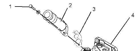

Illustration1g01075873
2.Removebolts(1).Removefuelprimingpumpassembly(2)fromfuelfilterbase(4).
3.Removegasket(3)fromthefuelprimingpumpassemblyandthefuelfilterbase.
InstallationProcedure
NOTICE
Keepallpartscleanfromcontaminants. Contaminantsmaycauserapidwearandshortenedcomponentlife.
Illustration2g01075873
1.Positiongasket(3)onfuelfilterbase(4).
2.Positionfuelprimingpumpassembly(2)onthefuelfilterbaseandinstallbolts(1).Tighten theboltstoatorqueof15±3N·m(11±2lbft).
3.Turnthefuelsupplytothe“ON”position.
4.Removetheairfromthesystem.RefertoTestingandAdjusting,"FuelSystem-Prime".
Copyright1993-2025CaterpillarInc. AllRightsReserved. PrivateNetworkForSISLicensees.
SatJul2619:41:16UTC+05302025
Product:TRUCKENGINE
Model:C15TRUCKENGINEMXS
Configuration:C15On-HighwayTruckMXS00001-UP
DisassemblyandAssembly
C15On-highwayEngines
MediaNumber-RENR9403-13PublicationDate-01/11/2017DateUpdated-29/11/2017 i02121646
FuelFilterBase-Remove
SMCS-1262-011
RemovalProcedure Table1
RequiredTools
ToolPartNumberPartDescriptionQty A185-3630StrapWrench1
NOTICE
Caremustbetakentoensurethatfluidsarecontainedduring performanceofinspection,maintenance,testing,adjusting,andrepair oftheproduct.Bepreparedtocollectthefluidwithsuitablecontainers beforeopeninganycompartmentordisassemblinganycomponent containingfluids.
RefertoSpecialPublication,NENG2500,"DealerServiceTool Catalog"fortoolsandsuppliessuitabletocollectandcontainfluidson Catproducts.
Disposeofallfluidsaccordingtolocalregulationsandmandates.
NOTICE
Keepallpartscleanfromcontaminants.


1.Turnthefuelsupplytothe“OFF”position. Illustration1g01080654
2.Disconnecthoseassembly(3)fromfuelfilterbase(4).
3.Disconnecthoseassembly(5).
4.Disconnecttubeassembly(6).
5.Disconnecttheharnessassemblyfromfuelpressuresensor(3).Removethefuelpressure sensorfromthefuelfilterbase.
6.UseTooling(A)toremovefuelfilter(7)fromfuelfilterbase(4).
7.Removebolts(1)andremovethefuelfilterbase.
Copyright1993-2025CaterpillarInc. AllRightsReserved. PrivateNetworkForSISLicensees.
SatJul2619:41:47UTC+05302025
Product:TRUCKENGINE
Model:C15TRUCKENGINEMXS
Configuration:C15On-HighwayTruckMXS00001-UP
DisassemblyandAssembly
C15On-highwayEngines
MediaNumber-RENR9403-13PublicationDate-01/11/2017DateUpdated-29/11/2017
FuelFilterBase-Disassemble
SMCS-1262-015
DisassemblyProcedure
StartBy:
a.Removethefuelfilterbase.RefertoDisassemblyandAssembly,"FuelFilterBaseRemove".
NOTICE
Keepallpartscleanfromcontaminants. Contaminantsmaycauserapidwearandshortenedcomponentlife.
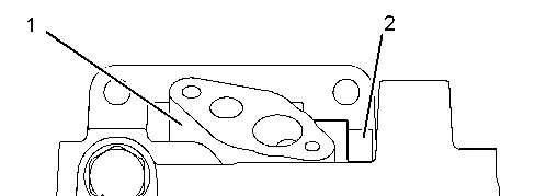
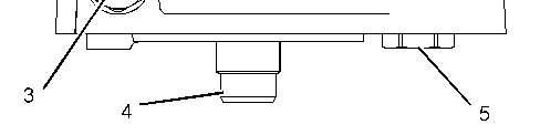
Illustration1g01063845
1.Removefuelbypassvalve(2)fromfuelfilterbaseassembly(1).RemovetheO-ringseals fromthefuelbypassvalve.
2.Removefuelcheckvalve(5)fromfuelfilterbaseassembly(1).RemovetheO-ringseals fromthefuelcheckvalve.
3.Removefitting(3)fromfuelfilterbaseassembly(1).RemovetheO-ringsealsfromthe fitting.
4.Ifnecessary,removehollowstud(4)fromfuelfilterbaseassembly(1).
Copyright1993-2025CaterpillarInc. AllRightsReserved. PrivateNetworkForSISLicensees.
SatJul2619:42:02UTC+05302025
Product:TRUCKENGINE
Model:C15TRUCKENGINEMXS
Configuration:C15On-HighwayTruckMXS00001-UP
DisassemblyandAssembly
C15On-highwayEngines
MediaNumber-RENR9403-13PublicationDate-01/11/2017DateUpdated-29/11/2017
FuelFilterBase-Assemble
SMCS-1262-016
AssemblyProcedure
Table1
RequiredTools
ToolPartNumberPartDescriptionQty A155-0695ThreadLockCompound-
NOTICE
Keepallpartscleanfromcontaminants. Contaminantsmaycauserapidwearandshortenedcomponentlife.
1.InstalltheO-ringsealsonfuelbypassvalve(2).Installthefuelbypassvalveinfuelfilter baseassembly(1).
2.InstalltheO-ringsealsonfuelcheckvalve(5).Installthefuelcheckvalveinfuelfilter baseassembly(1).Tightenthefuelcheckvalvetoatorqueof28±3N·m(21±2lbft).
3.InstalltheO-ringsealsonfitting(3).Installthefittinginfuelfilterbaseassembly(1).
4.Ifnecessary,installhollowstud(4)tofuelfilterbaseassembly(1).Tightenthehollowstud toatorqueof70±15N·m(52±11lbft).
Note:ApplyTooling(A)tothefirst7.6±0.8mm(0.30±0.03inch)ofthreadsatthebase endofthetaperlockstud.
EndBy:Installthefuelfilterbase.RefertoDisassemblyandAssembly,"FuelFilterBaseInstall".
Copyright1993-2025CaterpillarInc. AllRightsReserved. PrivateNetworkForSISLicensees.
SatJul2619:42:25UTC+05302025
Product:TRUCKENGINE
Model:C15TRUCKENGINEMXS
Configuration:C15On-HighwayTruckMXS00001-UP
DisassemblyandAssembly
C15On-highwayEngines
MediaNumber-RENR9403-13PublicationDate-01/11/2017DateUpdated-29/11/2017 i02121648
FuelFilterBase-Install
SMCS-1262-012
InstallationProcedure NOTICE
Keepallpartscleanfromcontaminants. Contaminantsmaycauserapidwearandshortenedcomponentlife.
1.Positionfuelfilterbase(4)onthecylinderblock.Installbolts(1).
2.Installfuelfilter(7)onthefuelfilterbase.Followthedirectionsonthefuelfilterforthe correctinstallationprocedure.Donotovertightenthefuelfilter.
3.Connecthoseassembly(3)tothefuelfilterbase.
4.Connecthoseassembly(5)tothefuelfilterbase.
5.Connecttubeassembly(6)tothefuelfilterbase.
6.Installfuelpressuresensor(3).Connecttheharnessassemblytothefuelpressuresensor.
7.Turnthefuelsupplytothe“ON”position.
8.Removetheairfromthesystem.RefertoTestingandAdjusting,"FuelSystem-Prime".
Copyright1993-2025CaterpillarInc. AllRightsReserved. PrivateNetworkForSISLicensees.
SatJul2619:42:39UTC+05302025
Product:TRUCKENGINE
Model:C15TRUCKENGINEMXS
Configuration:C15On-HighwayTruckMXS00001-UP
DisassemblyandAssembly
C15On-highwayEngines
MediaNumber-RENR9403-13PublicationDate-01/11/2017DateUpdated-29/11/2017
FuelTransferPump-Remove
SMCS-1256-011
RemovalProcedure
NOTICE
Caremustbetakentoensurethatfluidsarecontainedduring performanceofinspection,maintenance,testing,adjusting,andrepair oftheproduct.Bepreparedtocollectthefluidwithsuitablecontainers beforeopeninganycompartmentordisassemblinganycomponent containingfluids.
RefertoSpecialPublication,NENG2500,"DealerServiceTool Catalog"fortoolsandsuppliessuitabletocollectandcontainfluidson Catproducts.
Disposeofallfluidsaccordingtolocalregulationsandmandates.
NOTICE
Keepallpartscleanfromcontaminants. Contaminantsmaycauserapidwearandshortenedcomponentlife.
1.Turnthefuelshutoffvalvetothe“OFF”position.
2.Disconnectthefuelsupplylineatthefueltransferpump.


3.Disconnecttubeassembly(4).
4.Removebolts(3).
5.Removefueltransferpump(1)fromfronthousing(5).
6.RemoveO-ringseal(2)fromthefueltransferpump.
Copyright1993-2025CaterpillarInc. AllRightsReserved. PrivateNetworkForSISLicensees.
SatJul2619:42:56UTC+05302025
Product:TRUCKENGINE
Model:C15TRUCKENGINEMXS
Configuration:C15On-HighwayTruckMXS00001-UP
DisassemblyandAssembly
C15On-highwayEngines
MediaNumber-RENR9403-13PublicationDate-01/11/2017DateUpdated-29/11/2017
FuelTransferPump-Install
SMCS-1256-012
InstallationProcedure
NOTICE
Keepallpartscleanfromcontaminants. Contaminantsmaycauserapidwearandshortenedcomponentlife.
1.InstallO-ringseal(2)onfueltransferpump(1).LubricatetheO-ringsealwithcleanengine oil.
2.Positionthefueltransferpumponfronthousing(5).Installbolts(3).
3.Connecttubeassembly(4).
4.Connectthefuelsupplylinetothefueltransferpump.
5.Turnthefuelsupplyvalvetothe“ON”position.
6.Removetheairfromthefuelsystem.RefertoTestingandAdjusting,"FuelSystemPrime".
Copyright1993-2025CaterpillarInc. AllRightsReserved. PrivateNetworkForSISLicensees.
SatJul2619:43:11UTC+05302025
Product:TRUCKENGINE
Model:C15TRUCKENGINEMXS
Configuration:C15On-HighwayTruckMXS00001-UP
DisassemblyandAssembly
C15On-highwayEngines
MediaNumber-RENR9403-13PublicationDate-01/11/2017DateUpdated-29/11/2017
ElectronicUnitInjector-Remove
SMCS-1290-011
RemovalProcedure Table1
RequiredTools
ToolPartNumberPartDescriptionQty A5F-4764PryBar1
StartBy:
a.Removethevariablevalveactuator.RefertoDisassemblyandAssembly,"ValveActuator (Variable)-Remove".
b.Removetherockerarmsandtherockerarmshaft.RefertoDisassemblyandAssembly, "RockerArmandShaft-Remove".
NOTICE
Caremustbetakentoensurethatfluidsarecontainedduring performanceofinspection,maintenance,testing,adjusting,andrepair oftheproduct.Bepreparedtocollectthefluidwithsuitablecontainers beforeopeninganycompartmentordisassemblinganycomponent containingfluids.
RefertoSpecialPublication,NENG2500,"DealerServiceTool Catalog"fortoolsandsuppliessuitabletocollectandcontainfluidson Catproducts.
Disposeofallfluidsaccordingtolocalregulationsandmandates.
NOTICE
Keepallpartscleanfromcontaminants. Contaminantsmaycauserapidwearandshortenedcomponentlife.

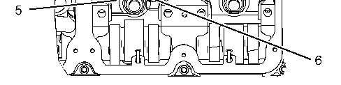
Illustration1g01076052
1.Disconnectharnessassembly(1).
2.Removebridgeassemblies(3).
NOTICE
Iftheinjectorholddownboltislooseduringtheremovalprocedure, inspecttheinjectorboreforwearanddebris.Replacetheclampand spacer.
3.Removebolt(4),spacer(5),andclamp(6).
4.Placeanidentificationmarkonelectronicunitinjector(2)forinstallationpurposes.Each electronicunitinjectormustbereinstalledintheoriginallocationinthecylinderhead.


Illustration2g01076047
5.UseTooling(A)toprybeneaththebaseandfreeelectronicunitinjector(2).
6.Removetheelectronicunitinjectorfromthecylinderhead.
Copyright1993-2025CaterpillarInc. AllRightsReserved. PrivateNetworkForSISLicensees.
SatJul2619:43:21UTC+05302025
Product:TRUCKENGINE
Model:C15TRUCKENGINEMXS
Configuration:C15On-HighwayTruckMXS00001-UP
DisassemblyandAssembly
C15On-highwayEngines
MediaNumber-RENR9403-13PublicationDate-01/11/2017DateUpdated-29/11/2017
ElectronicUnitInjector-Install
SMCS-1290-012 InstallationProcedure
169-7372FluidSamplingBottle1 4C-4057Tube7.9mm(0.31inch)OD1
D4C-5552LargeBoreBrush1
E4C-6774VacuumGunKit 1
F8T-7765SurfaceReconditioningPad1
G 9U-6862TaperedBrush 9U-7237BrushExtension NOTICE
Keepallpartscleanfromcontaminants. Contaminantsmaycauserapidwearandshortenedcomponentlife.
1.UseTooling(C)toremovethefuelandoilfromthecylinder.Evacuateasmuchfuelandoil aspossiblefromthecylinderbeforeinstallingtheelectronicunitinjector.Several evacuationsmaybenecessary.

2.UseTooling(D)tocleanthecarbondepositfromtheinsidetheelectronicunitinjector sleeveatLocation(Z).Tooling(E)isavailabletocleanloosematerialfromtheboreofthe electronicunitinjectorsleeveandthecylinder.
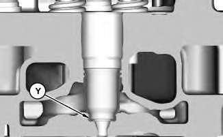
Illustration2g03722826
Sectionview.
3.UseTooling(F)tocleanthecarbonfromtheseatareaatlocation(Y)thatisinsidethe electronicunitinjectorsleeve.
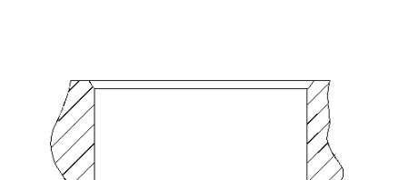

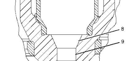

Illustration3g03722522
4.UseTooling(G)tocleaninjectorseatingarea(8)andinjectortipbore(9).

Illustration4g03718585
5.UsealintfreematerialtocleanO-ringseals(7)andelectronicunitinjector(2).
6.LubricatethetoptwoO-ringseals(7)withTooling(A).Donotuseanyotherlubricant.
Note:OnceO-ringseals(7)arelubricated,installimmediately.
Note:DonotreuseO-ringseals(7).
Note:O-ringseals(7)mustbestoredproperlytopreventcontamination.
7.InstallO-ringseals(7)ontheelectronicunitinjector.
Note:CautionmustbetakentoavoidoverstretchingtheO-ringseals(7).
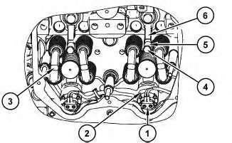
Illustration5g03729389
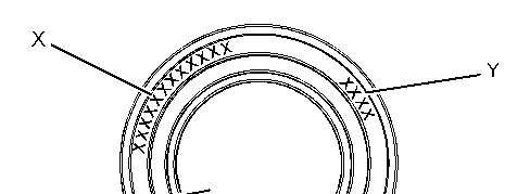

Illustration6g01135876
8.Whenyouinstallanewinjector,theE-Trimvaluemustbeprogrammedintotheengine controlmodule.Theinjectorconfirmationcodemayneedtobeprogrammedintotheengine controlmodule.E-TrimValue(X)isa12-digitalphanumericcodethatissuppliedwiththe datasheetthatcomeswiththenewinjectors.InjectorConfirmationCode(Y)isafour-digit numericcode.Bothofthecodesareonthetopofelectronicunitinjector(2).Usethe followingmenutoprogramtheE-Trimvalue.
ECMSummaryScreen
ServiceMenu
Calibration
InjectorCodeCalibration
NOTICE
Whenanelectronicunitinjectorisreplaced,thenewelectronic injectorcodemustbeprogrammedintotheengine'spersonality modulesoftwarebyusingthecalibrationmenuontheElectronic ServiceTool.Ifthenewelectronicinjectorcodeisnotentered,the characteristicsofthepreviouselectronicunitinjectorisassumed. Ifitisnotpossibletoimmediatelyreprogramtheelectronicinjector codeintothepersonalitymodulesoftware,theenginewillnotbe severelyharmed.Thenewelectronicinjectorcodeshouldbe reprogrammedasquicklyaspossibleinordertooptimizeengine performance.
9.Assembleelectronicunitinjector(2)withtheclamp(6),spacer(5),andnewbolt(4). Positionelectronicunitinjector(2)intheinjectorbore.
Note:CautionmustbeusedtoavoiddamagingO-ringseals(7)arenotdamagedwhen positioningelectronicunitinjector(2)intheinjectorbore.
Note:Donotpushormanuallyforceelectronicunitinjectorintothebore.
10.Tightenbolt(4)toatorqueof55±10N·m(41±7lbft).Ensurethatelectronicunitinjector (2)isalignedintheborewhiletighteningbolt(4).
Note:Tightenbolt(4)ataslowanduniformrate.Ifapneumaticorelectrictoolisused, caremustbetakentoavoiddamagetotheO-ringduetoquicklyseatingtheinjector.
Note:Tighteningbolt(4)tocorrecttorquewillproperlyseatelectronicunitinjector(2).
11.Inspectareaaroundtheboreforelectronicunitinjector(2)toensurethatO-ringseals(7) werenotdamagedorextruded.
12.Installbridgeassemblies(3).
13.Connectharnessassembly(1).Tightenthenutstoatorqueof2.5±0.25N·m(22±2lbin).
EndBy:
a.Installtherockerarmsandtherockerarmshaft.
Copyright1993-2025CaterpillarInc. AllRightsReserved. PrivateNetworkForSISLicensees.
SatJul2619:43:32UTC+05302025
Product:TRUCKENGINE
Model:C15TRUCKENGINEMXS
Configuration:C15On-HighwayTruckMXS00001-UP
DisassemblyandAssembly
C15On-highwayEngines
MediaNumber-RENR9403-13PublicationDate-01/11/2017DateUpdated-29/11/2017 i02169626
ElectronicUnitInjectorSleeve-Remove
SMCS-1713-011
RemovalProcedure
Table1 RequiredTools
ToolPartNumberPartDescriptionQty
A9U-6891InjectorToolGroup1
StartBy:
a.Removetheelectronicunitinjectors.RefertoDisassemblyandAssembly,"ElectronicUnit Injector-Remove".
NOTICE
Keepallpartscleanfromcontaminants. Contaminantsmaycauserapidwearandshortenedcomponentlife.
1.Drainthecoolantfromtheengine.RefertoOperationandMaintenanceManual,"Cooling SystemCoolant-Change".
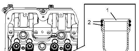

2.InstallTooling(A)inelectronicunitinjectorsleeve(1).
3.TightenthenutonTooling(A)untiltheelectronicunitinjectorsleeveispulledfreeofthe cylinderhead.
4.RemoveO-ringseals(2)andO-ringseal(3)fromelectronicunitinjectorsleeve(1).
Copyright1993-2025CaterpillarInc. AllRightsReserved. PrivateNetworkForSISLicensees.
SatJul2619:43:50UTC+05302025
Product:TRUCKENGINE
Model:C15TRUCKENGINEMXS
Configuration:C15On-HighwayTruckMXS00001-UP
DisassemblyandAssembly
C15On-highwayEngines
MediaNumber-RENR9403-13PublicationDate-01/11/2017DateUpdated-29/11/2017 i02536688
ElectronicUnitInjectorSleeve-Install
SMCS-1713-012
InstallationProcedure
Table1 RequiredTools
ToolPartNumberPartDescriptionQty
9U-6862TaperedBrush1
9U-6863SmallBoreBrush1
B
9U-7244EndBrush 1
9U-7237BrushExtension1
4C-5552LargeBoreBrush1
C(1)221-9778PullerStud1
D(1)9U-7258DriverCap1
E4C-9507RetainingCompound-
(1)Partofthe9U-6891InjectorToolGroup
NOTICE
Keepallpartscleanfromcontaminants. Contaminantsmaycauserapidwearandshortenedcomponentlife.
1.UseTooling(B)tocleantheboreinthecylinderheadfortheelectronicunitinjectorsleeve.
NOTICE
Ensurethattheelectronicunitinjectorsleeveandthecylinderhead borearecompletelyfreeofoil,dirt,andsealantdebris.
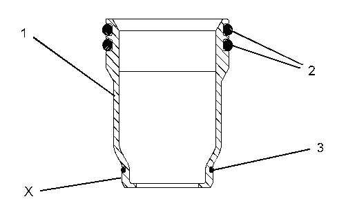
2.InstallnewO-ringseals(2)andO-ringseal(3)onelectronicunitinjectorsleeve(1).
Note:DonotapplyTooling(E)tothecylinderheadsurfaces.ApplyTooling(E)onthe electronicunitinjectorsleeveonly.
3.ApplyTooling(E)tothecontactsurfaceofelectronicunitinjectorsleeve(1)onthesurface thatisMarked"X".
4.LubricateO-ringseals(2)withcleanengineoil.
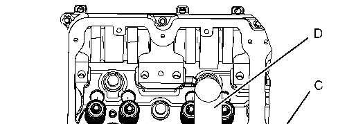
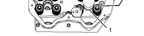
Illustration2g01076119
5.InstallTooling(C)intothethreadsofelectronicunitinjectorsleeve(1).
6.PositionTooling(C)andtheelectronicunitinjectorsleeveinthecylinderhead.Usecare nottodamagetheO-ringsealsontheelectronicunitinjectorsleeve.
7.UseTooling(D)andahammertoinstallelectronicunitinjectorsleeve(1)inthecylinder head.
NOTICE
Ensurethattheelectronicunitinjectorsleeveisproperlyseatedinthe cylinderhead.TheToolingwill"RING"whentheelectronicunit injectorsleeveisfullyseatedintheboreofthecylinderhead.
8.RemoveTooling(D)andTooling(C).UseacleantowelandremoveexcessTooling(E).
9.Fillthecoolingsystemwithcoolant.RefertoOperationandMaintenance,"Refill Capacities"forthecoolingsystemcapacity.
EndBy:
a.Installtheelectronicunitinjectors.RefertoDisassemblyandAssembly,"ElectronicUnit Injector-Install".
Copyright1993-2025CaterpillarInc. AllRightsReserved. PrivateNetworkForSISLicensees.
SatJul2619:44:00UTC+05302025
Product:TRUCKENGINE
Model:C15TRUCKENGINEMXS
Configuration:C15On-HighwayTruckMXS00001-UP
DisassemblyandAssembly
C15On-highwayEngines
MediaNumber-RENR9403-13PublicationDate-01/11/2017DateUpdated-29/11/2017
Turbocharger-Remove-LowPressure
SMCS-1052-011
RemovalProcedure
NOTICE
Caremustbetakentoensurethatfluidsarecontainedduring performanceofinspection,maintenance,testing,adjusting,andrepair oftheproduct.Bepreparedtocollectthefluidwithsuitablecontainers beforeopeninganycompartmentordisassemblinganycomponent containingfluids.
RefertoSpecialPublication,NENG2500,"DealerServiceTool Catalog"fortoolsandsuppliessuitabletocollectandcontainfluidson Catproducts.
Disposeofallfluidsaccordingtolocalregulationsandmandates.
NOTICE
Keepallpartscleanfromcontaminants. Contaminantsmaycauserapidwearandshortenedcomponentlife.
NOTICE
Failuretofollowestablishedprocedurescanleadtodamageofthe parts.
Toavoiddamagetotheparts,alwaysidentifyandmarkthepartsso thatthepartscanbeinstalledinthesamelocation.
1.Putidentificationmarksonthebellowsforalignmentandorientationduringinstallationof thebellows.
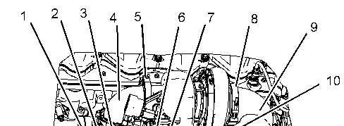
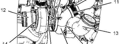

Illustration1g01076551
2.Loosenclampassembly(8).Loosenclampassembly(11).
Theendsofthebellowsareverysharp.Injurycouldoccurifthebellows arenothandledproperly.Handlethebellowsbytheconvolutions.
Note:RefertoSpecialInstruction,REHS1728,"ApplicationGuidelinefortheBellows"for additionalinformationonhandlingthebellows.
3.Removeairinletelbow(9)andbellows(10)fromtheturbochargers.
4.Loosenclampassembly(5).Loosenclampassembly(2).
Theendsofthebellowsareverysharp.Injurycouldoccurifthebellows arenothandledproperly.Handlethebellowsbytheconvolutions.
Note:RefertoSpecialInstruction,REHS1728,"ApplicationGuidelinefortheBellows"for additionalinformationonhandlingthebellows.
5.Removeduct(4)andbellows(3)fromtheturbochargers.
6.Disconnecthose(7).
7.Disconnecthoseassembly(6).
8.Disconnecthoseassembly(15).
9.Loosenclampassembly(17).Removeinletelbow(13)andtheO-ringsealfromthe turbocharger.
10.Removelocknuts(14).Removeexhaustelbow(12)andthegasketfromtheturbocharger.
11.Removelocknuts(1).
12.Useasuitableliftingdeviceinordertoremoveturbocharger(16).Theweightofthe turbochargerisapproximately29kg(65lb).
Copyright1993-2025CaterpillarInc. AllRightsReserved. PrivateNetworkForSISLicensees.
SatJul2619:44:26UTC+05302025
Product:TRUCKENGINE
Model:C15TRUCKENGINEMXS
Configuration:C15On-HighwayTruckMXS00001-UP
DisassemblyandAssembly
C15On-highwayEngines
MediaNumber-RENR9403-13PublicationDate-01/11/2017DateUpdated-29/11/2017
Turbocharger-Remove-HighPressure
SMCS-1052-011
RemovalProcedure
NOTICE
Caremustbetakentoensurethatfluidsarecontainedduring performanceofinspection,maintenance,testing,adjusting,andrepair oftheproduct.Bepreparedtocollectthefluidwithsuitablecontainers beforeopeninganycompartmentordisassemblinganycomponent containingfluids.
RefertoSpecialPublication,NENG2500,"DealerServiceTool Catalog"fortoolsandsuppliessuitabletocollectandcontainfluidson Catproducts.
Disposeofallfluidsaccordingtolocalregulationsandmandates.
NOTICE
Keepallpartscleanfromcontaminants. Contaminantsmaycauserapidwearandshortenedcomponentlife.