


 Ellis Bridge Manek Burj
East Riverfront Road
Ellis Bridge Manek Burj
East Riverfront Road


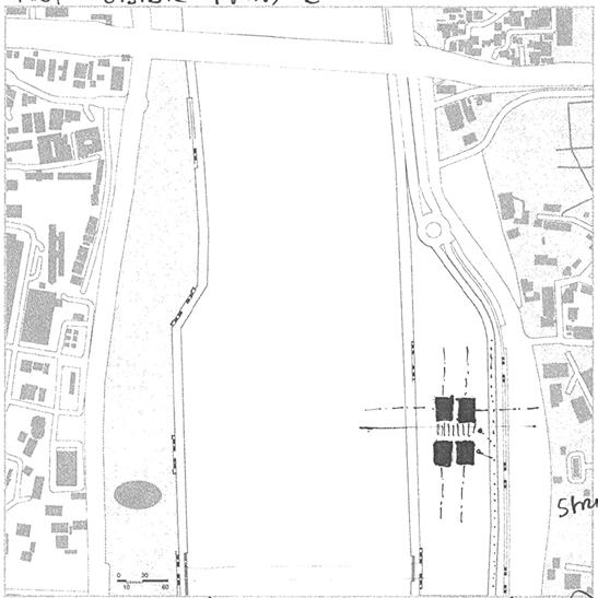
Site is located on Eastern Riverfront area between Atal Bridge and Ellis veloped city on Western edge. The land was reclaimed from the slum close to Fort wall. In a way, the land was taken from one group of user the city. Hence the site hold utmost Socio-Cultural value. All the exploration were done by taking into account

Fig. 01 - Existing activity direction on
Aspiration
Making a green space
• More of a
• More for the local population
• Programme should become a part of daily
• To connect river and the public i.e redefining the lower and Upper which physical connect to the river is lost and
• To be pause point, place of small break/rest and
• To turn the barren and somewhat lifeless
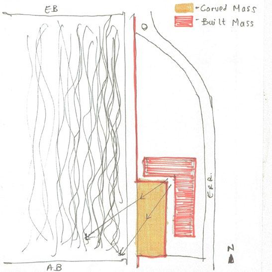
The thought process started with figure-ground sketches where modification portions on site and built mass to void
The second round focused on exploring singular built mass to fragmented to possible access (Page-
The thrid set of drawings shows 3D explorations of few selected explorations
In fourth and fifth sets of parties shows the spatial explorations through tion to aspiration statement were selected and systems such as Spanning, Tectonic was identified (Page-
bridge. It hase dense old city fabric on East, Sabarmati river and new dedwellers and Sunday market activity was relocated along its Eastern edge user to make a public and entertainment space for larger mass of users - For exploration of siting, scale of built form, spacial experience and SYSTEM account this very important aspect of site.

and around site
Aspiration Statement: space for daily users.
a public nature. population than for the tourists. daily routine of people in surrounding area. Upper promanade edges to break linear activites along the river due to and only visual connection is happening. (Fig. 01) and refreshment in a rather monotonous daily route. lifeless land into a greener, public space.
modification of site edges, understanding the scale of built mass in various provoid relation was explored. (Page- 5-6)
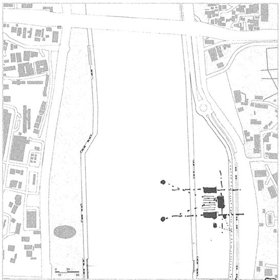
fragmented built mass and their organisation and placement on site with respect access points and vistas.
(Page- 7-8)
explorations from the second set of figure and ground parties. (Page- 9-10)
through space parties, sections and plans. Few of them showing strong connecSpanning, Bearing, Enclosure, Surfaces and their nature such as Stereotomic or identified in them.
(Page- 11-14)


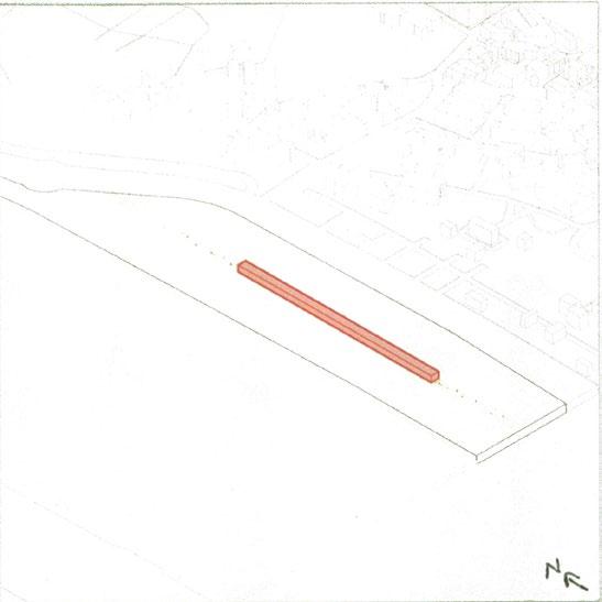
1,500 Sq. m - 30 M x 50 M x 6 M

1,500 Sq. m - 10 M x 150 M x 6 M

Carving the promanade and redefining the edge

Carving the promanade and redefining the edge Variation 2

1,500 Sq. m - 20 M x 75 M x 6 M
1,500 Sq. m - 7.5 M x 200 M x 6 M

Structure in center and access from multiple points

Structure in center and access from multiple points Variation 3

1,500 Sq. m - 15 M x 100 M x 6 M

Carving the promanade and redefining the edges

Orientation and placement of built mass on site Variation 1

Orientation and placement of built mass on site Variation 4

Carving the promanade + Variation 1

Merging cycle track and structure - Intersection


Merging cycle track and redefining Eastern edge

Merging cycle track and structure - Intersection


Merging cycle track and structure - Intersection

Merging cycle track and structure - Intersection


Placement of sungle built mass on site with reference to vertical access point around site which are possible entry points.

Equal division of mass - Variation 3 Questioning the orientation

Equal division of mass - Variation 6 How far to be displaced?


Same position - Equal division of mass - Variation 1

Equal division of mass - Variation 4 Questioning the distance

Equal division of mass - Variation 7 Axis rotation, possible vista


Equal division of mass - Variation 2 Questioning the orientation

Equal division of mass - Variation 5 Parallel displacement

Equal division of mass - Variation 8 Axis rotation, possible vista from East Riverfront road


Equal division of mass - Variation 12 2 axis, inbetween space between volumes facing new city

Division of mass in three equal parts - Variation 3 3 axis, questioning the distance between volumes
Division of mass in four equal parts - Variation 3 Storng symmetry, increasing distance along one axis


Division of mass in three equal parts - Variation 1 3 axis, inbetween space between volumes framing the west edge t

Division of mass in four equal parts - Variation 1 Storng symmetry


Division of mass in four equal parts - Variation 2 Storng symmetry, increasing distance along one axis

Division of mass in four equal parts - Variation 4 Storng symmetry, increasing distance along both axis t Division of mass in four equal parts - Variation 6
organization,
and
in
Division of mass in four equal parts - Variation 6

Division of mass in four equal parts - Variation 6


Figure and Ground diagrams and Isometric views


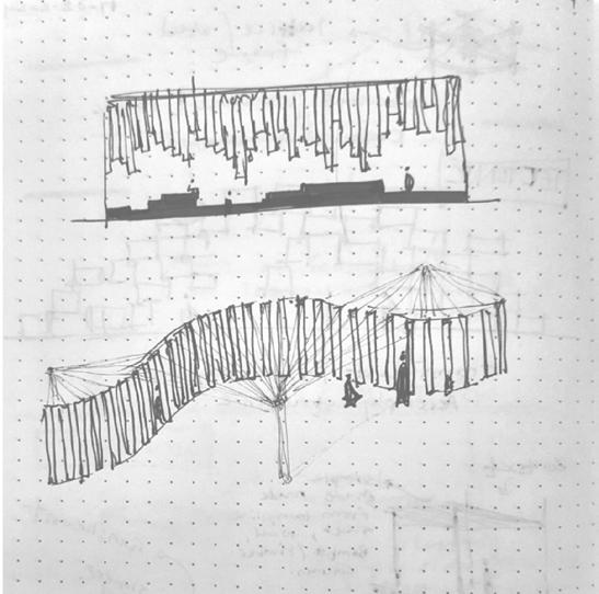


Figure and Ground diagrams and Isometric views


Figure and Ground diagrams and Isometric views


Figure and Ground diagrams and Isometric views


The evolution of system, inferences form case studies seen in parti diagrams selected previously was studied through system diagrams in next stage. (System evolution diagrams - 1 to 3) Few of them which supported strongly the aspiration statement were identified and classified in a ‘System matrix’ where the nature of space and system a Stereotomic or Tectonic and the dominating system in them were explored. This served as framework to create the most relevant system combinations.


Green roof Roof as activity plane Underground structure
Enclosure for directionality Thickness for multiple uses such as furniture, seating etc.
Thick walls and green roof to reduce heat gain, use them in multiple ways.
Porous roof for light
Combination 1) : 1 + 3 + C
Translucent enclosure for light, and visual conncetivity
Combination 2) : 1 + 2 + C
Sleek structure and double enclosure with dynamic function of opening and losing helping in sunshading as well as addition of extra space as and when required.
Combination 3) : A + B + 3

Porous roof + dynamic opening of tectonic enclosure and 'A' frame profile + stereotomic walls


Porouity of roof + translucent enclosure + stereotomic roof


Underground structure + stereotomic walls + dynamic opening of tectonic enclosure


Earthwork
A part of site is scooped and the edge between lower and upper promanade is modified
Hearth
The scopoped part of site has subtle contours which slopes toward river. This creats a very subtle transition from lower to upper promanade and vice-versa and also helps to connect to river.
Enclosure - Tectonic
The other parallel sides of the structure is a tectonic enclosure containing two layersInner layer - Sliding glass panels
External layer - Rotating screen of timber square sections with metal frame.
Framework - Enclosure - Stereotomic
The main framework is two parallel walls of tapering profile casted on site in pigmented concrete.
Framework - Enclosure - Tectonic
The single pathway with a complete tectonic structure intersects the solid walls and connects all the structures.
Roof - Tectonic
The structures has roof made of GLT pargola and glass on top. This helps to bring in more natural light inside.
Roof75 mm x 450 mm GLT beam resting on top of RCC beam with insulated toughned glass on top GLT - RCC Beam joinery - 8 mm thk MS gusset plate half anchored in RCC beam while casting and other half connedted to GLT with ‘through bolts’.
BuildingInternal enclosure - Sliding glass panels
External enclosure - Rotating timber screen - 3” x 3” Square section @ 3” C/C with metal framing - 4” x 4” MS SHS

Building - 350 mm x 600 mm RCC beam with same pigment @ 3,600 mm C/C
Building - Tilted in-situ casted concrete walls with Ocher pigment to match site colour
Pathway - 2” x 2” MS pipe pargola @ 300 mm C/C
Pathway - 4” x 4” MS pipe framing @ 2,100 mm C/C
Pathway - Perforated sheet floor
Pathway - 4” x 4” x 8 mm thk ‘L’ sections as vertical supports with 4” x 4” MS SHS frame to support floor
RCC Plinth with Ocher pigment to match site colour
Contours
Exploded view of system

The location of visitor centre in site is chosed stratgically which is adjacent to Atal bridge between the two staircases connecting the lower and upper A subtle slope is created from South-East to North-West which helps to create a smooth transition from lower pormenade to site covering the height This helps to give glimpses of river from far behind the Upper promenade edge and increase the visual connection. The building modules are placed in a way that the tectonic encolsure would face the river and allows for multiple vistas. Each contour on top which A single continuous pathaway with pargola roof connects all modules. The tectonic enclosure of pathway allows user to walk on to the surrounding


The library building is a 2 floor module. The RCC beams connecting the two walls are placed at 3.6 M C/C which determines the length of building modules.
The library building has 3 bay formed by these beam grids. 1st bay houses the Librarian desk and circulation area connected to the external pathway. The middle bay contains a timber staircase which serves in multiple ways. It connects both floors, its riser height allows it to be used a informal amphitheatre seating. These high risers contains storage inside them which is used for storing the books. The last by is the quiet work-read area with table and chairs arranged in groups of 2 or 4. The upper floor has work-read area and book racks on either sides of staircase bay.


GLT and Glass roof as per detail
2” ø pipe for water supply for plants
- Drip irrigation
2” x 2” extra cover at inner edges of wall
Soil
8” thk layer of gravel
4” ø french drain pipe for excess water drainage
Geotextile fabric on 3 sides
Root barrier on 3 sides
China Tukdi - Waterproofing 3 sides
Brick bat coba - 1 layer
6” thk RCC slab
Plaster with Golai-Ghotai
100 mm thk RCC pardi
RCC beam - 350 mm x 600 mm
Exposed concrete wall600 mm thk at plinth level; 200 mm thk at top 3” thk rigid foam insulation
Interior envelope - sliding glass panels
Exterior envelope - Rotating timber screen with metal framing
Sandstone flooringMatching colour with concrete pigment
Timber staircase + bookshelf -
1. Stringer beam 150 mm thk
2. secondary beam - 100 mm thk
3. timber shelves - 1” thk
Raised floor by 450 mm -
Timber framework and flooring
150 mm thk RCC plinth slab
Gravel filling
Compact earth filling
Exposed concrete wall footing1. Shoe 2. Toe 3. shear key
Depth as per structural designer
Gutter in landscape - 300 mm x 450 mmwith grating on top


THANK YOU!