

FERRITE CORES
Toroids • Shapes • Pot Cores
Part Number Index
TOROIDS E CORES SHAPES
TOROID PGTOROID PG
E, IPGPLANAR E, IPGEC PG
40904EC2841425EC3243517EC42
41203EC2841434EC3244119EC42
41205EC2841434IC3245224EC42
41707EC2841805EC3247035EC42
41808EC2841805IC32 EER
41810EC2842107EC3242814EC44
42510EC2842107IC3242817EC44
42513EC2842214EC3243521EC44
42515EC2842214IC3244013EC44
42520EC2842216EC3244216EC44
42526EC2842216IC3244818EC44
42530EC2842217EC3244821EC44
43007EC2843208EC3245418EC44
U, I PGPot
41106UC3840704UG54
41106IC3840905UG54
42220UC3841107UG54
42512UC3841109UG54
42515UC3841408UG54
42516IC3841811UG54
42530UC3841814UG54
49316UC3842213UG54
49316IC3842438UG54
49330UC3842616UG54
49332UC3842823UG54
49920UC3843019UG54
49925UC3843622UG54
47325TC26
43009EC2843208IC32 EFD
43515EC2843618EC3241009EC46
43520EC2843618IC3241212EC46
44011EC3043808EC3441515EC46
44016EC3043808IC3442019EC46
44020EC3043809EC3442523EC46
44020IC3044008EC3443030EC46
44022EC3044008IC34 ETD
44033EC3044308EC3442929EC48
44317EC3044308IC3443434EC48
44721EC3044310EC3443939EC48
45528EC3044310IC3444444EC48
45530EC3045810EC3444949EC48
45724EC3045810IC3445454EC48
46016EC3046410EC3445959EC48
46022EC3046410IC3447054EC48
46527EC3049938EC34
47133EC30 ER
47228EC3040906EC36
48020EC3041126EC36
49928EC3041308EC36
41308IC36
41426EC36
41826EC36
42014EC36
42014IC36
42313EC36
42517EC36
42517IC36
42521EC36
43021EC36
43021IC36
43225EC36
49925IC3844229UG54 UR RS-DSPG
44119UC4041408UG56
44121UC4041811UG56
44125UC4042311UG56
44130UC4042318UG56
45716UC4042616UG56
45917UC4043019UG56
46420UC4043622UG56
BLOCK 44229UG56
41106IC50 PQ
41308IC5042016UG58
41805IC5042020UG58
42014IC5042610UG58
42107IC5042614UG58
42216IC5042620UG58
42516IC5042625UG58
43208IC5043214UG58
43618IC5043220UG58
43808IC5043230UG58
44008IC5043535UG58
44020IC5044040UG58
44308IC5045050UG58
44310IC50 RM
45810IC5041110UG60
46410IC5041510UG60
49316IC5041812UG60
49925IC5041912UG60
49938FB5042013UG60
49966FB5042316UG60
49985FB5042819UG60 EP 43723UG60
40707UG5244230UG60
41010UG52
41313UG52
41717UG52
42120UG52


Applications & Materials

Ferrites are dense, homogenous ceramic structures made by mixing iron oxide with oxides or carbonates of one or more metals such as zinc, manganese, nickel or magnesium. They are pressed, then fired in a kiln at 1,000 - 1,500°C and machined as needed to meet various operational requirements. Ferrite parts can be easily and economically molded into many different geometries. A diverse set of materials, providing a range of desired electrical and mechanical properties, are available from Magnetics.
Magnetics’ ferrite cores are manufactured for a wide variety of applications. Magnetics has the leading MnZn ferrite materials for power transformers, power inductors, wideband transformers, common mode chokes, as well as many other applications.
ADVANTAGES OF MAGNETICS’ FERRITES
• The widest range of toroid sizes in power and high permeability materials
• Superior toroid coatings available in epoxy and Par ylene C
• Standard gapping to precise inductance or mechanical dimension: wide range of coil former and assembly hardware available
• The full range of standard planar E and I cores
• Rapid prototyping capability for new development
FERRITE APPLICATIONS
Broadband Transformers
Common Mode Chokes
Low loss, high µ. Good frequency response.
Very high µ (permeability).
Converter and Inverter TransformersLow losses, high saturation.
Differential Mode Inductors
Linear Filters and Sensors
Narrow Band Transformers
Noise Filters
Power Inductors
Power Transformers
Pulse Transformers
Telecom Inductors
Low losses, high temperature stability, good stability across load conditions.
Good loss factor, linearity and temperature linearity at low drive level.
W, M
Pot cores, Toroids, E, U & I cores, RM cores, EP cores
W, M Toroids, E Cores
L, P, R, T
P, R, T
Toroids, E, U & I cores, Pot cores, RS cores, Planar cores
Gapped Pot cores, EP cores, E cores, RM cores, Planar cores, PQ cores
cores, Toroids
Moderate Q, high µ, high stability. F, J Pot cores, Toroids, RM cores, EP cores
High µ, good frequency response.
Low losses at high flux densities and temperatures. High saturation. Good stability across load conditions.
High µ and low losses at high flux densities and temperatures. High saturation. Low exiting currents.
High µ, low loss, high B saturation.
Low losses, high temperature stability, good stability across load conditions.
J, W, M Toroids
F, L, P, R, T
F, L, P, R, T
Pot cores, E cores, PQ cores, RM cores, Planar cores
Ungapped Pot cores, E, U & I cores, Toroids, EP cores, RS cores, DS cores, PQ cores, Planar cores
J, W, M Toroids
F, P, R, T
Pot cores, EP cores, E cores, RM cores, Planar cores
Ferrite Materials


Power Loss (PL) Sine Wave in mW/cm3 (typical)
25 kHz
200 mT (2,000 G)
100 kHz
100 mT (1,000 G)
@25˚C 901806080
@60˚C 651105575
@100˚C 60659070
@120˚C 6511012575
@25˚C 87707065
@60˚C 64506557
@100˚C 586511055
@120˚C 644515058
@25˚C 290
500 kHz
50 mT (500 G)
@60˚C150
@100˚C115175300 150
@120˚C130
Resistivity r Q
Ferrite Materials

TYPICAL MECHANICAL PROPERTIES OF FERRITE MATERIALS
MECHANICAL DATA
Bulk Density 4.85 g/cm3 Coefficient of Linear Expansion10.5x10-6 °C-1
Tensile Strength 5.0, 7.0x10³ kgf.mm-2, lbs.in-2 Specific Heat (25°) 800 J/kgK
Compressive Strength45, 63x103 kgf.mm-2, lbs.in-2 Thermal Conductivity (25-85°C)3500-4300µW.mm-1.°C-1
Youngs Modulus12.4x103,1.8x107 kgf.mm-2, lbs.in-2 35-43 mW.cm-1.°C-1
Hardness (Knoop) 650 Typical .0083-.010cal.s-1.cm-1.°C-1
Resistivity


R Material
A medium frequency multi-purpose power transformer, inductor and filter material. Widely available in shapes and toroids. Engineered for lowest losses between 90-100°C.
Initial Perm (25°C; ^10 kHz) ......................... 2,300 ± 25%
Saturation Flux Density (4,700 G at 15 Oe, 25°C) 470 mT, 11.9 A·T/cm
Curie Temperature ........................................... 210°C
P Material
A low-medium frequency general-purpose power converter material. Engineered for lowest losses between 80 - 100°C. Available in almost all core sizes and shapes. Initial Perm (25°C; ^10 kHz) ........................ 2,500 ± 25%
Saturation Flux Density (4,700 G at 15 Oe, 25°C)
Curie Temperature
F Material
A medium frequency general-purpose power transformer, inductor and filter material. Slightly higher in perm than P or R Material. Lowest losses between 50 - 80°C.
T Material
A power material for transformers and inductors operating from 20 kHz to 750 kHz. T material offers stability in both perm and losses over a wide temperature range.
L Material
A high-frequency high-temperature power material. L material is optimized for transformers and inductors from 500 kHz – 3 MHz. Core losses are minimized between 70 – 100°C.
C Material
PERMEABILITY(µ)
C Material works well for Telecom Filters, Wideband, Matching and Pulse transformer applications, and High Q inductors. TYPICAL B-H LOOPS
Initial Perm (25°C; ^10 kHz), Uncoated ................... 900 ± 25%
Saturation Flux Density 380 mT, 11.9 A·T/cm (3,800 G at 25°C, 15 Oe) Curie Temperature ...........................................
vs. FREQUENCY
E Material
E Material works well for Telecom Filters, Wideband, Matching and Pulse transformer applications, and High Q inductors.
V Material
V Material works well for Telecom Filters, Wideband, Matching and Pulse transformer applications, and High Q inductors.
J Material
A medium perm general-purpose material. Well suited both for EMI/RFI filtering and broadband transformers.
Initial Perm (25°C; ^10 kHz) .........................
W Material
A high permeability material used for EMI/RFI suppression, common mode chokes, pulse and broadband transformers.
Initial Perm (25°C; ^10 kHz) (<87mm OD) ............
± 30% Initial Perm (≥87mm OD)
Flux Density
M Material
Highest permeability material used for EMI/RFI suppression, common mode chokes, pulse and broadband transformers.
Initial Perm (25°C; ^10 kHz) ........................
± 30% Saturation Flux Density (4,700 G at 15 Oe,
Gapped Cores
How To Order
Part Number
0P44317 A450
Same as for ungapped cores Gap Code
Gap Code
The letter indicates the type of gap and a three-digit number defines the value.
CODEMEANING EXAMPLE
A_ _ _AL (if <1000)
X_ _ _ AL if 1000 or greater (add 1000 to code)
F_ _ _ AL if <100, non-integer (divide code by 10)
G_ _ _ Depth of Grind in mils (1000ths of an inch)
M_ _ _ Depth of Grind, mm (divide code by 10)
DF42311A275 (AL=275)
OP44721X250 (AL=1250)
OR42510F807 (AL=80.7)
OF44317G079 (Gap=0.079”)
OF43019M015 (Gap=1.5 mm)
AL is inductance factor, mH/1000 Turns, or nH/T². Either the AL or the depth of grind (not both) is controlled during production of gapped cores.
See the chart on pages 17-19 for tolerances.
Gap-to-Gap vs Ungapped-to-Gap Core Sets
“Gap-to-gap combination” means the gap is symmetrical. Half of the total gap is removed from each piece.
“Ungapped-to-gap combination” means an asymmetrical gap; the entire gap is taken from one piece, and the other piece is ungapped.
For an E-core gapped to an AL value when mated with the standard I-core, add “-EI” to the end of the part number.
Gapping for AL
Inductors are commonly designed with an airgap in the magnetic path where the center legs or center posts of two ferrite pieces meet. This airgap allows the inductance to be controlled to a tight tolerance, and it allows the inductor to support a defined level of DC current without saturating. Inductors are commonly designed with an airgap in the magnetic path where the center legs or center posts of two ferrite pieces meet. This airgap allows the inductance to be controlled to a tight tolerance, and it allows the inductor to support a defined level of DC current without saturating. In most applications, defining the gap with the AL results in inductors with the least variation.
When specifying and ordering E cores (including EC, EFD, EER, ETD, and Planar E cores) gapped to an AL, it is important to note which cores are produced in gap-to-gap combination, because two gapped pieces are assembled to achieve the AL. Alternatively, for E cores provided ungapped-to-gap, an ungapped piece must be used with a gapped piece to achieve the AL. Pot, RS, DS, RM, PQ, and EP cores are sold as sets whether the combination is gap-to-gap or ungapped-to-gap.
AL testing and limits are calculated to three significant digits based on the nominal value. For example, AL=99±3% is interpreted as 96.0 Minimum, 99.0 Nominal, and 102.0 Maximum.
Magnetics tests gapped AL values with full bobbins, usually 100 turns, or 250 turns for deep gaps. The drive level is low (0.5 mT) and the frequency is set low enough to avoid resonance effects. Measured inductance in an application may vary significantly from the theoretical value due to low turns, low bobbin fill, leakage effects, resonance effects, or elevated drive levels.
It is important for users to verify the correlation between the test of the core and the specific test being applied to the inductor or transformer. Planar E cores, Planar RM, and Planar PQ cores are especially susceptible to correlation discrepancies.
Gapping for Depth of Grind
Even though controlling AL is usually the way to get the best consistency in finished inductor performance, in some cases the best results are seen when the depth of grind is specified instead. This is generally in cases where the gap dimension is quite large (the AL is low), because variation in the inductance of the wound device is dominated by variation in the windings, especially if the number of turns is low.
For parts ordered in pieces (E cores), the depth of grind is given for each piece. To make an ungapped-to-gap set, use one piece of each. For example, use 0R41808G050 with 0R41808EC for an asymmetrical gap of 0.050”± 0.001. For the same gap, but symmetrical, use two pieces of 0R41808G025.
For parts ordered in sets, the depth of grind is given as a total for the set, and may be ungapped-to-gap core pieces or gap-to-gap.
Gapped Cores Depth of Grind Tolerances
Tolerance Ranges for Pot, RS, DS, RM, PQ, and EP cores
Tolerance Ranges for E, EC, ER, EER, EFD, ETD and Planar E cores INCHES
MILLIMETERS
to gap combination 0.039”– 0.076”± 0.001”± 0.0015”± 0.002”1.0
Ungapped to gap combination (Except if the gap is more than 10% of the minimum bobbin depth for the set*, then gap-to-gap combination.)
Gap to gap combination (Except if the gap is less than 10% of the minimum bobbin depth for the set*, then ungapped-to-gap combination.)
0.12 mmGap to gap combination
*The bobbin depth for the set is the 2D dimension or 2 times the D dimension
INCHES
Gapped Cores
AL Value Tolerances
E CORES*
PAGES 28 - 31
4120316-2728-55≤86≤117≤160 4120528-4748-107≤170≤229≤316 4170722-3738-89≤140≤190≤259 4180827-4243-121≤192≤258≤355 4181044-7475-235≤376≤512≤704 4251037-6162-200≤318≤432≤595 4251528-4344-210≤333≤452≤616 42520107-190191-397≤643≤874≤1202 4253045-7273-409≤655≤891≤1225 4300742-6768-307≤491≤668≤919 4300955-9192-222≤353≤475≤653 4351554-8788-429≤687≤934≤1284 4352065-111112-461≤738≤1003≤-1380 4401159-9596-642≤1029≤1400≤1940
4401652-8384-545≤872≤1185≤1629
4402078-126127-916≤1480≤1999
4402294-156157-1187≤1903≤1999
4431781-136137-762≤1222≤1676≤1999
44721107-180181-1188≤1920≤1999
45528113-186187-500≤1999
45530150-360361-600≤1999
45724129-218219-450≤1999
46016102-129130-1231≤1999
46527142-235236-650≤ 1999
47133150-285286-950≤1999
47228120-199200-1823≤1999
4802099-158159-1922≤1999
49928150-285286-975≤1999
EC CORES
PAGES 42 - 43
4351749-7980-438≤702≤954≤1312
4411961-9899-627≤1004≤1365≤1891
4522476-123124-911≤1471≤1999
4703583-135136-1403≤1999
*These tolerances also apply to E-I combination.
PLANAR E CORES*
PAGES 32 - 35 4142519-3536-76≤122≤166≤228 4143417-3132-77≤123≤167≤230 4180518-3233-205≤329≤448≤617 4210735-6667-188≤304≤414≤569 4221678-141142-405≤656≤892≤1239 43208118-216217-643≤1040≤1427≤1964 43618119-222223-673≤1088≤1491≤1999 43808173-315316-956≤1547≤1999 44008106-189190-507≤821≤1116≤1548 44308201-367368-1130≤1828≤1999 44310169-305306-1130≤1828≤1999 45810266-481482-1496≤1999 46410379-701702-1999 49938336-594595-1999
ER CORES*
PAGES 36 - 37
4090615-6566-70≤110≤150≤200 4112640-7475-100≤140≤190≤275 4142645-8485-130≤190≤250≤380 4182650-8485-200≤325≤445≤650 4231355-9091-200≤525≤710≤900 4302180-169170-710≤1050≤1460≤1975
EER/ETD CORES
PAGES 44 - 45/48 - 49
4343455-8889-500≤806≤1095≤1507 4352154-8687-566≤913≤1241≤1707 4393995-156157-641≤1028≤1398≤1935 4421671-117118-876≤1415≤1925≤1999 4444473-117118-881≤1423≤1935≤1999 4494981-130131-1075≤1736≤1999 4595951-118119-1822≤1999
EFD CORES
4121218-2930-90≤130≤170≤230 4151519-3031-81≤127≤172≤236 4201929-4546-220≤350≤430≤575 4252341-6667-296≤475≤646≤888 4303050-9091-450≤790≤975≤1125 SIZE GAP TO GAP ± 3% UNGAPPED TO GAP COMBINATION
PAGES 46 - 47
Gapped Cores
AL Value Tolerances
SIZE GAP TO GAP ± 3% UNGAPPED TO GAP COMBINATION ±3%±5%±7%±10%
EP CORES
PAGES 52 - 53
4070725-5051-75≤125 ≤160
4101025-5556-75≤125 ≤160
4131325-7576-110≤175≤275≤315
4171725-100101-175≤275≤400≤630
4212025-180181-450≤630≤850≤1250
POT CORES
PAGES 54 - 55
4070425-3536-62≤95≤125≤175
4090525-4849-87≤135≤180≤240 4110725-7576-135≤220≤285≤399
4140871-113114-210≤307≤417≤574
4181196-174175-326≤523≤712≤988 4181465-135136-340≤510≤700≤980
42213113-204205-482≤779≤1060≤1459
42616139-249250-695≤1125≤1543≤1999
43019170-304305-1015≤1642≤1999
43622222-399400-1494≤1999
44229169-389390-1965≤1999
RS (ROUND-SLAB) CORES
PAGES 56 - 57
41408 25-177≤283≤385≤530 4181125-3940-270≤400≤525≤800 4231125-3940-347≤708≤963≤1325 4231825-3940-452≤731≤994≤1378
4261625-3940-622≤998≤1369≤1884 4301925-6263-918≤1485≤1999
4362240-6263-1286≤1999 4422940-6263-1732≤1999
DS (DOUBLE SLAB) CORES
PAGES 56 - 57
42311109-195196-386≤625≤850≤1170 4231878-135136-441≤706≤961≤1332 42616117-205206-580≤930≤1276≤1756 43019149-264265-873≤1412≤1922≤1999 43622170-300301-1111≤1797≤1999 44229179-315316-1543≤1999
PQ CORES
PAGES 58 - 59
4201660-184185-467≤755≤1027≤1425 4202050-139140-467≤754≤1026≤1422 42610200-396397-777≤1258≤1728≤1999 42614110-334335-645≤1044≤1421≤1972 4262095-296297-888≤1436≤1955≤1999 4262577-234235-880≤1423≤1936≤1999 43214127-416417-548≤885≤1207≤1661 43220128-409410-486≤1369≤1878≤1999 4323084-241242-808≤1305≤1775≤1999 4353589-255256-980≤1575≤1999 4404083-230231-1006≤1625≤1999 45050128-210210-1999
RM CORES
PAGES 60 - 61
4111025-5051-55≤75≤170≤250 4151056-9899-162≤258≤352≤484 4181269-120121-238≤381≤519≤714 4191269-120121-238≤381≤519≤714 4231684-150151-395≤633≤862≤1195 42819126-200201-625≤1002≤1374≤1892 43723145-250251-977≤1580≤1999
Chart shows type of combination and the guaranteed tolerance for corresponding AL ranges. Ranges indicated are the tolerances for standard gaps. For ± 5%, ± 7%, and ± 10%, the maximum AL for each is shown. Standard cores are manufactured to the smallest allowed tolerances. EE and EI tolerances are identical.
2.54 mm – 12.7 mm
HOW TO ORDER
O J 4 14 06 TC
Coating code
Ferrite core material
Used for all ferrite types
Approximate diameter in mm
Approximate height in mm
Geometry code
Ferrite toroids offer high magnetic efficiency as there is no air gap, and the cross sectional area is uniform. Available in many sizes (O.D. from 2.54 mm to 140 mm) and materials (permeabilities ranging from 750 to 15,000), this section lists common sizes.
Typical applications for high permeability toroids (J, W, and M materials) include common mode chokes, broadband transformers, pulse transformers and current transformers. L, R, P, F and T material toroids are excellent choices for high frequency transformers.
NOMINAL AL (mH/1000T)
3,3086,6169,988599


2.54
4.83

12.7
3,9137,82511,072690 25.34
HOW TO ORDER O J 4 14 06 TC
Coating code
Ferrite core material
Used for all ferrite types
Approximate diameter in mm
Approximate height in mm
Geometry code
12.7
41.8
44.3
HOW TO ORDER O J 4 14 06 TC
Coating
Ferrite
Approximate
Approximate
Geometry
4,4008,800
16,73033,400
11,60023,200
8,07516,100
32
44.3
49.1 mm – 140 mm
HOW TO ORDER O J 4 14 06 TC
Coating code
Ferrite
Used
Approximate
Approximate
Geometry code Coating
6,06512,130
7,43514,870
6,57511,178
49.1
85.7
E, I Cores
9 mm – 35 mm
E cores are less expensive than pot cores and have the advantage of simple bobbin winding plus easy assembly. E cores do not, however, offer self-shielding. Lamination size E cores are available to fit commercially offered bobbins previously designed to fit the strip stampings of standard lamination sizes. Metric and DIN sizes are also available. E cores can be pressed to different thicknesses, providing a selection of cross-sectional areas. E cores can be mounted in different directions and, if desired, provide a low profile.
Typical applications for E cores include differential mode, power and telecom inductors, as well as broadband, power, converter and inverter transformers.
9/4/2 0_40904EC 280493540650 1,040 E 13/7/3 0_41203EC 350587640770 1,367
E 13/7/6 0_41205EC 7001,4671,6001,950 3,300
E 17/7/4 0_41707EC 5201,0131,1001,300 1,900
E 19/8/5 0_41808EC 5501,1531,2531,5001,5002,5004,293
E 19/8/10 0_41810EC 1,0002,3002,5003,000 5,0008,600
E 25/10/7 0_42510EC 8001,7671,9202,300 3,7007,660
E 25/13/7 0_42513EC 9001,9002,3142,460 4,000
E 25/16/6 0_42515EC 5401,1531,2531,500 2,400
E 25/10/13 0_42520EC 1,6003,5333,8404,600 7,40013,813
E 25/13/11 0_42526EC
E 25/16/13
1,0702,3072,5073,000 4,8008,213 E 31/15/7 0_43007EC 9202,0602,2402,700 3,8008,200
E 31/13/9 0_43009EC 1,4002,8933,1473,780 5,893
E
E 34/14/9 0_43515EC 2,6672,9073,500 5,81311,414
HOW TO ORDER
O R 4 30 07 EC
Shape code
Ferrite core material
Used for all ferrite types
Approximate length in mm
Approximate height in mm
Geometry code
GEOMETRY CODE
EC – E core
IC – I core
Cores are sold per piece (for sets multiply by 2).
See page 18 for information on gapped cores.
For an E-core gapped to an AL value when mated with the standard I-core, add “-EI” to the end of the part number.


E 9/4/2 0_40904EC 15.65.03.6780.0020.7 E 13/7/3 0_41203EC 27.810.110.12790.0161.3
E
DIMENSIONS (mm)
E
E, I Cores
40 mm – 100 mm
E
E
E
HOW TO ORDER
O R 4 72 28 EC
Shape code
Ferrite core material
Used for all ferrite types
Approximate length in mm
Approximate height in mm
Geometry code
GEOMETRY CODE
EC – E core
IC – I core
Cores are sold per piece (for sets multiply by 2).
See page 18 for information on gapped cores. For an E-core gapped to an AL value when mated with the standard I-core, add “-EI” to the end of the part number.

7,78011,850
Planar E, I Cores
HOW TO ORDER
C R 4 14 34 EC
Shape code
Ferrite core material
Used for all ferrite types
Approximate length in mm
Approximate width in mm
Geometry code
SHAPE CODE
C – Planar core with clip recesses
F or 0 – Planar core without clip recesses
GEOMETRY CODE
EC – Planar E core • IC – Planar I core
For clip slot dimensions see individual datasheets. Cores are sold per piece (for sets multiply by 2). See page 18 for information on gapped cores. For an E-core gapped to an AL value when mated with the standard I-core, add “-EI” to the end of the part number.
Planar E cores are offered in all of the IEC standard sizes and a number of other sizes. The leg length and window height (B and D dimensions) are adjustable for specific applications without new tooling. This permits the designer to adjust the final core specification to exactly accommodate the planar conductor stack height with no wasted space. Clips and clip slots are available in many cases, which is useful for prototyping. I cores are also offered standard, reducing path length and increasing inductance. Planar cores provide the lowest profile design. E-I planar combinations allow practical face bonding in high volume assembly. The flat back can accommodate a heat sink.
Differential mode inductors, DC/DC, and AC/DC converters are typical applications for planar cores.


DIMENSIONS
Planar E, I Cores

HOW TO ORDER
C R 4 64 10 EC
Shape code
Ferrite core material
Used for all ferrite types
Approximate length in mm
Approximate width in mm
Geometry code
SHAPE CODE
C – Planar core with clip recesses
F or O – Planar core without clip recesses
GEOMETRY CODE
EC – Planar E core
IC – Planar I core
For clip slot dimensions see individual datasheets. Cores are sold per piece (for sets multiply by 2).
See page 18 for information on gapped cores.
For an E-core gapped to an AL value when mated with the standard I-core, add “-EI” to the end of the part number.
ER Cores
HOW TO ORDER
O R 4 09 06 EC
Shape code
Ferrite core material
Used for all ferrite types
Approximate length in mm
Approximate depth in mm
Geometry code
SHAPE CODE
C – ER core with clip recesses
F or O – ER core without clip recesses
GEOMETRY CODE
EC – ER core
IC – I core
For clip slot dimensions see individual datasheets. ER cores are sold per piece (for sets multiply by 2).
See page 18 for information on gapped cores. For an E-core gapped to an AL value when mated with the standard I-core, add “-EI” to the end of the part number.
ER cores are a cross between planar E cores and pot cores. The round center post of the ER core offers minimal winding resistance. In addition, they offer better space utilization and shielding than with rectangular center leg planar cores. When compared with non-planar cores, ERs offer minimal height and better thermal performance. E/I combinations facilitate economical assembly. Typical applications of ER cores include differential mode inductors and power transformers.
NOMINAL


Refer to page 62 for additional hardware information.
DIMENSIONS (mm)
U, I Cores
U
I
HOW TO ORDER
O F 4 22 20 UC
Shape code
Ferrite core material
Used for all ferrite types
Approximate length in mm
Approximate width in mm
Geometry code
GEOMETRY CODE
UC – U core
IC – I core
U and I cores are sold per piece (for sets multiply by 2).
U cores are ideal for many power transformer applications. The long legs support low leakage inductance designs and facilitate superior voltage isolation. U/I combinations provide for economical assembly.
NOMINAL AL (mH/1000T)

U 25/13/13 0_42512UC
U 25/16/6 0_42515UC
I 25/6/6 0_42516IC
U 25/16/12 0_42530UC

U 93/76/32 0_49332UC 353905896319,0001851,600
U 126/91/20 0_49920UC 480560560268,8002861,360
U 102/57/25 0_49925UC 308645645199,000121988
I 102/25/25 0_49925IC 245645645158,00060.7784
UR Cores
HOW TO ORDER
O 4 41 25 UC
Shape code
Ferrite core material
Used for all ferrite types
Approximate length in mm
Approximate depth in mm
Geometry code
UR cores are sold per piece (for sets multiply by 2).
*For UR 64 size, refer to datasheets for differences in geometry.
UR cores are an excellent choice for high current designs and conditions where vibration occurs. The open window area accommodates large conductors. Holes through the center or grooves on the outer legs of the core provide a method to secure the core to the PCB with mounting hardware.
Typical applications include welding output transformers, audio amplifiers, traction, and other highvoltage power transformers.
NOMINAL AL (mH/1000T)

16317117127,9008.84140

18921021039,70013.8198
21029029061,00021.9320
EC Cores
HOW TO ORDER
O R 4 70 35 EC
Shape code
Ferrite core material
Used for all ferrite types
Approximate length in mm
Approximate width in mm
Geometry code
EC cores are sold per piece (for sets multiply by 2).
See page 18 for information on gapped cores.
The round center leg and open window of EC cores allow for minimum winding resistance and efficient assembly. Long legs promote low and controlled leakage inductance and are useful for high voltage applications.
EC cores have standard channels for clamping assemblies. Plain bobbins, printed circuit bobbins and clamps are available for most sizes.
Magnetics EC cores are typically used in differential mode inductor and power transformer applications.
NOMINAL AL (mH/1000T)


DIMENSIONS
EER Cores
EER cores are an economical choice for transformers and inductors. The round center leg offers the advantage of a shorter winding path length than winding around a square center leg of equal area.
Differential mode inductors and power transformers are typical applications for Magnetics EER cores.
HOW TO ORDER
Shape code
Ferrite core material
Used for all ferrite types
Approximate length in mm
Approximate height or width in mm
Geometry code
EER cores are sold per piece (for sets multiply by 2).
See page 18 for information on gapped cores. O R 4 42 16 EC


EFD Cores
The industry standard flat design of EFD cores offers excellent space utilization for transformers or inductors. The optimized cross-sectional area is ideal for very flat compact transformer applications.
EFD cores are designed for compact transformers and inductor applications.
HOW TO ORDER
O R 4 15 15 EC
Shape code
Ferrite core material
Used for all ferrite types
Approximate length in mm
Approximate width (per set) in mm
Geometry code
EFD cores are sold per piece (for sets multiply by 2).
See page 18 for information on gapped cores.


ETD Cores
HOW TO ORDER
Shape code
Ferrite core material
Used for all ferrite types
Approximate length in mm
Approximate height (per set) in mm
Geometry code
ETD cores are sold per piece (for sets multiply by 2.)
See page 18 for information on gapped cores. O R 4 39 39 EC
ETD cores are an economical choice for transformers or inductors. ETDs offer a round center leg for minimum winding resistance. Dimensions are optimized for power transformer efficiency.
Typical applications of Magnetics ETD cores include differential mode inductors and power transformers.
NOMINAL AL (mH/1000T)


DIMENSIONS (mm)
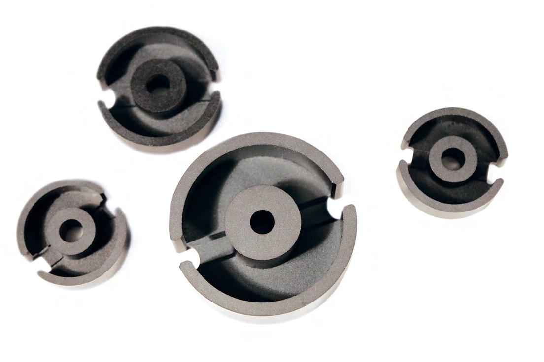
Block Cores
Ferrites can be pressed in block form and then machined into intricate shapes. Where large sizes are required, it is possible to assemble them from two or more smaller machined or pressed sections; the variety of sizes and shapes becomes limitless.
Features of Magnetics ferrite blocks include low porosity, extreme hardness, uniform physical properties, high density and ease of machining. J material offers high permeability; R material is suitable for power applications.
AVAILABLE MATERIALS
TYPE/SIZE ORDERING CODE L R P F J
I 11/4/6 0_41106IC PPPP
I 12.5/8.5 0_41308IC PPPP
I 18 F_41805IC PPPP
I 20/7/14 F_42014IC PPPP
I 22/4/7 0_42107IC PPPP I 22 F_42216IC PPPP
I 25/6/6 0_42516IC PPPPP I 32 F_43208IC PPPP
I 36/6/18 0_43618IC PP I 38 F_43808IC PPPP
I 40/4/10 0_44008IC PPPP
I 43/6/15 0_44020IC PP
I 43/4/28 0_44308IC PPP I 43 F_44310IC PPP I 58 F_45810IC PPP I 64 F_46410IC PPP
I 93/28/16 0_49316IC PPPP
I 102/25/25 0_49925IC PPP
FB 104/66/18 0_49966FB PP P
FB 100/85/25 0_49985FB P
FB 120/120/38 0_49938FB P
HOW TO ORDER
O R 4 99 66 FB
Shape code
Ferrite core material
Used for all ferrite types
Approximate length in mm
Approximate height in mm
Geometry code
GEOMETRY CODE
IC – I core
FB – Block core
Block cores and I cores are sold per piece.


DIMENSIONS (mm)
EP Cores
EP cores are round center post cubical shapes which enclose the coil completely except for the printed circuit board terminals. This particular shape minimizes the effect of air gaps formed at mating surfaces in the magnetic path and provides a larger volume ratio to total space used. EP cores provide excellent shielding.
Typical applications for EP cores include differential mode and telecom inductors and signal transformers.
7
5901,0801,1731,240 2,5735,143
10 P_41010UG 5301,040 1,1331,2001,3602,4674,800 EP 13 P_41313UG 7601,5331,6672,0002,0003,7337,143 EP 17 P_41717UG 1,1202,3872,6003,1003,1005,86711,429
1,9304,2274,6005,0005,0009,60019,286
HOW TO ORDER
P J 4 10 10 UG
Shape code
Ferrite core material
Used for all ferrite types
Approximate length in mm
Approximate height (per set) in mm
Geometry code
EP cores are sold in sets.
See page 19 for information on gapped cores.

DIMENSIONS (mm)

Pot Cores
Pot cores offer superior shielding and convenient mounting. Typical applications for pot cores include differential mode inductors, power transformers, power inductors, converter and inverter transformers, broadband and narrowband filters, transformers and telecom inductors.
NOMINAL AL (mH/1000T)
PC 7/4
PC 9/5
PC 11/7
PC 11/9 0_41109UG 1,4671,5731,900
PC 14/8 0_41408UG 2,0532,2402,8002,8005,0738,4001,1002,1002,240
PC
PC 22/13 0_42213UG 4,0404,4004,9005,2009,10016,0001,7003,9004,650
PC 34/28 0_42438UG 7,550
PC 26/16 0_42616UG 5,2135,6676,350 11,70020,000 6,000
PC 28/23 0_42823UG 7,000
PC 30/19 0_43019UG 6,6807,2678,100 15,10025,0002,8008,0007,000
PC 36/22 0_43622UG 8,7009,46710,20010,80017,50032,667 9,000
PC 42/29 0_44229UG 9,20010,00012,00011,450 40,000 9,000
HOW TO ORDER
O P 4 14 08 UG
Shape code
Ferrite core material
Used for all ferrite types
Approximate diameter in mm
Approximate height (per set) in mm
Geometry code
Pot cores are sold in sets. See page 19 for information on gapped cores.

PC
DIMENSIONS (mm)
RS-DS Cores
HOW TO ORDER
S P 4 23 11 UG
Shape code
Ferrite core material
Used for all ferrite types
Approximate length in mm
Approximate height (per set) in mm
Geometry code
SHAPE CODE
D - DS Core with solid center post
H - DS Core with center hole
S - RS core
RS-DS cores are sold in sets.
See page 19 for information on gapped cores.
*For DS 42/29 size, see datasheets for differences in geometry.
Slab cores are the same as pot cores except for wider wire openings. A slab piece can be paired with a standard pot core round to make an RS combination, or two slabs can be paired for a double slab (DS).
The RS geometry offers most of the shielding of a pot core but with more space available for terminating leads. DS cores offer a good compromise between shielding and thermal management.
Typical applications for RS and DS combinations include low and medium power transformers, switched-mode power supplies, and multiple output converter and inverter transformers.
NOMINAL AL (mH/1000T)


PQ Cores
HOW TO ORDER
O R 4 20 16 UG
Shape code
Ferrite core material
Used for all ferrite types
Approximate length in mm
Approximate height (per set) in mm
Geometry code
PQ cores are sold in sets.
For clip slot dimensions see individual data sheets. See page 19 for information on gapped cores.
PQ cores are designed specifically for switched mode power supplies. One result is an optimized ratio of volume to winding area and surface area, meaning that maximum inductance and winding area are possible with a minimum core size. The cores provide maximum power output with minimum assembled transformer weight and volume, in addition to taking up a minimum amount of area on the printed circuit board.
Assembly with printed circuit bobbins and one piece clamps is simplified. PQs provide a more uniform cross-sectional area, so they tend to operate with less pronounced hot spots than most other cores.
Typical applications include power transformers and power inductors.
NOMINAL AL (mH/1000T)


DIMENSIONS (mm)
RM Cores
RM cores are designed for wound assemblies with a square footprint for efficient use of PC board space. The wire openings allow space for multiple coil terminations and offer a balance between shielding and thermal performance.
Easy to assemble and adaptable to automation, completed units provide at least 40% savings in mounting area compared to a similar size pot core assembly.
Typical applications include differential mode inductors, power inductors, filter inductors, telecom inductors and broadband transformers.
RM 5 R_41510UG 1,7201,8672,100 4,1336,0008001,960
RM 6R N N_41812UG 1,2302,3872,6003,0802,8306,7078,600
RM 6R R_41812UG 2,1872,3332,800 5,9737,714 2,700
RM 6S N N_41912UG 1,2502,2132,4002,880 6,0008,600
RM 6S R_41912UG 1,9872,1602,600 5,3877,714
RM 7 N N_42013UG 1,4503,0583,2443,675 5,0019,571
RM 8 N N_42316UG 1,7002,7002,9335,2104,1008,00012,200
RM 8 R_42316UG 2,3472,5603,500 6,96010,600
RM 10 N N_42819UG 2,2004,0474,4005,5005,5009,98716,000
RM 10 R_42819UG 4.750
RM 12 N N_43723UG 4,6005,0006,0006,79011,80022,600
RM 14 N N_44230UG 7,0007,5408,7828,13013,09620,735
HOW TO ORDER
R P 4 15 10 UG
Shape code
Ferrite core material
Used for all ferrite types
Approximate diameter in mm
Approximate height (per set) in mm
Geometry code
SHAPE CODE
N – RM core with solid center post R – RM core with center hole
RM cores are sold in sets.
See page 19 for information on gapped cores.


35.552.036.91,8500.161100C2316B1
RM 10 N N_42819UG 44.696.689.14,3100.442200C2819B1 RM
1.0746PCB3723M1
Refer to page 62 for additional hardware information.
SIZETYPEP/N
0200 TCSMC06018A
SMH05025A
SMH07058A
0301 TCSMC06018A
SMH05025A
SMH07058A
0401 TCSMC06018A
SMH05025A
SMH07058A
0402 TCSMC06018A
SMH05025A
SMH07058A
0502 TCSMC06018A
SMH05025A
SMH07058A
0503 TCSMC06018A
SMH05025A
SMH07058A
0601 TCSMC06018A
SMH07058A
0603 TCSMC06018A
SMH07058A
0704 PC00B0704B1
0705 TCSMH07058A
0707
EP0AC070716
0BC070712
SMB07076A
0905 PC00B090501
0906 ER00C09061A
SMB09068A
1009 EFD00C1009B1
PCB1009B1
1010 EP00C10102A
PCB10108A
SMB10108A
1107 PC00B1107B1
00B1107A2
00C1107B1
1110 RM00C1110B1
1212 EFD00C1212B1
PCB1212B1
1313 EP0AC131316
0BC131314
PCB1313B1
SMB1313B1
1406 TCTVB22066A
TVH22064A
1407 TCTVB22066A
TVH22064A
SIZETYPEP/N
1408 PC00B140801
RS/DS00B140802
00C140811
00W140815
PCB140821
PCB1408S1
PCB1408TA
PCB1408TB
PCB1408TE
TBA140800
TCA1408B1
TCA1408C3
1450 TCTVB22066A
TVH22064A
1506 TCTVB22066A
TVH22064A
1510 RM00C1110B1
PCB1510B1
PCB15108A
TBP151000
1515 EFDSMB1515TA
00C1515B1
PCB1515B1
1605 TCTVB22066A
TVH22064A
1717 EP00C17172A
PCB17178A
1805 P-EC00C180520
1808 EC00B180801
PCB1808B1
1809 TCTVB22066A
TVH22064A
1811 PC00B181101
RS/DS00B181102
00B181103
00C181111
00W181118
PCB181111
PCB181112
PCB181121
PCB181122
TCA1811B1
1812 RM00C1812B1
TBA181201
TCA1812C2

SIZETYPEP/N
1912 RMTBA181201
TCA1812C2
2016 PQ00C201612
PCB2016FC
2019 EFD00C2019B1
PCB2019B1
2020 PQ00C202012
PCB2020FC
2106 TCTVB22066A
TVB2908TA
TVH22064A
TVH25074A
2109 TCTVB22066A
TVB2908TA
TVH22064A
TVH25074A
2120 EP0AC212016
0BC212016
PCB2120VB
2206 TCTVB22066A
TVB2908TA
TVH22064A
TVH25074A
2207 TCTVB22066A
TVB2908TA
TVH22064A
TVH25074A
2212 TCTVB22066A
TVB2908TA
TVH22064A
TVH25074A
2213 PC00B221301
00B221302
00B221303
00C221314
00W221324
0PC221314
PCB221311
PCB221321
TCF2213B1
2216 P-EC00C221620
2311 RS/DSPCB2311TA
2316
00C2316B1
2318 RS/DSPCB2318TA
SIZETYPEP/N
2507 TCTVB2908TA
TVH22064A
TVH25074A
2508 TCTVB2908TA
TVH22064A
TVH25074A
2510 EC00B251001
PCB2510V1
PCB2510V2
2515 EC-EC00B251501
2520 ECPCB2520TA
2523 EFD00C2523B1
PCB2523B1
2616 PC00B261601
RS/DS00B261602
00B261603
00C261614
0PC261614
PCB261611
PCB261612
PCB261613
PCB261621
PCB261622
PCB2616TA
TBP669000
TCF2800B1
2620 PQ00C262012
PCB2620LB
2625 PQ00C262512
PCB2625LB
2819 00C2819B1
2823 PC00B282301
2908 TCTVB2908TA
TVB3610FA
TVH25074A
2915 TCTVB2908TA
TVB3610FA
TVH25074A
2929 ETD00C2929B1
PCB2929B1
3009 ECPCB3009LA
3019 PC00B301901
RS/DS00B301902
00B301903
00C301917
PCB301911
PCB301921
PCB3019TA
TBP669000
TCF2800B1
3030 EFD00C3030B1
PCB3030B1
SIZETYPEP/N
3113 TCTVB2908TA
TVB3610FA
3205 TCTVB3610FA
TVH38134A
3208 P-EC00C320802
3220 PQ00C322017
PCB3220B1
3230 PQ00C323017
PCB3230B1
3434 ETD00C343416
PCB3434FB
3515 EC00B351501
PCB3515M1
PCB3515M2
3517 EC0CC351700
PCB351701
PCH351701
3521 EERPCB3521LA
3535 PQ00C353517
PCB3535LB
3610 TCTVH38134A
3615 TCTVB3610FA
TVH38134A
3622 PC00B362201
00C362217
PCB362211
PCB3622L1
TBP669000
TCF2800B1
TCF4000B1
3723 RMPCB3723M1
3806 TCTVB3610FA
TVH38134A
3813 TCTVB3610FA
TVH38134A
TVH49164A
3825 TCTVB3610FA
TVH38134A
TVH49164A
3939 ETD00C393916
PCB3939SB
4015 TCTVH49164A
4020 EC-IC00B402021
PCB4020N1
4022 ECPCB4022N1
4040 PQ00C404017
PCB4040FA
4119 EC00B411901
0AC411919
0CC411900
PCB411901
SIZETYPEP/N
4119 ECPCH411901
4216 EERPCB4216FA
4229 PC00B422901 RS/DS00B422902
00C422917
PCB4229L1
TBP669000
TCF2800B1
TCF4000B1
4317 ECPCB4317M1
00B4317B1
TCTVH49164A 4932 TCTVH49164A 4949 ETD00C494916
PCB494920
PCB4949WA
5050 PQ00B5050B1
5224 EC0CC522400
PCB522401
PCH522401 00B5224B1 5454 ETD00C5454B1
PCB5454B1 5528 EC00B5528B1
PCB5528WC 5530 ECPCB5530FA 5724 EC00B5724B1
PCB5724M1 5810 EC-IC00C581001 00C581002 5959 ETD00C595916
PCB5959AA 6113 TCTVH49164A
TVH61134A 6326 TCTVH49164A
TVH61134A 6410 EC-IC00C641001
00C641002
6527 EC00B652701
7035 EC00B703501
PCB703501
PCH703501
7228 EC00B722801
8020 EC00B8020B1
Power Design
CORE GEOMETRIES
POT CORES
Pot cores, when assembled, nearly surround the wound bobbin. This aids in shielding the coil from pickup of EMI from outside sources. The pot core dimensions follow IEC standards so that there is interchangeability between manufacturers. Both plain and printed circuit bobbins are available, as are mounting and assembly hardware.
ROUND SLAB, DOUBLE SLAB & RM CORES
Slab-sided solid center post cores resemble pot cores, but have a section cut off on either side of the skirt. The additional openings allow larger wires to be accommodated and assist in removing heat from the assembly. RM cores are also similar to pot cores, but are designed to minimize board space, providing at least a 40% savings in mounting area. Printed circuit or plain bobbins are available. One-piece clamps permit simple assembly. Low profile is possible. The solid center post generates less core loss and minimizes heat buildup.
PQ CORES
PQ cores are designed specifically for switched mode power supplies. One result is an optimized ratio of volume to winding area and surface area, meaning that maximum inductance and winding area are possible with a minimum core size. The cores provide maximum power output with minimum assembled transformer weight and volume, in addition to taking up a minimum amount of area on the printed circuit board.
Assembly with printed circuit bobbins and one piece clamps is simplified. PQs provide a more uniform cross-sectional area, so they tend to operate with less pronounced hot spots than most other cores.
EC, ETD AND EER CORES
These shapes combine the benefits of E cores and pot cores. Like E cores, they have a wide opening on each side. This provides ample space for the large wires used for low output voltage switched mode power supplies. It also increases the flow of air which keeps the assembly cooler. The center leg is round, like that of the pot core. One of the advantages of the round center leg is that the winding has a shorter path length around it (11% shorter) than the wire around a square center leg with an equal area. This reduces the losses of the windings by 11% and
Ferrite is an ideal core material for transformers, inverters and inductors in the frequency range 20 kHz to 3 MHz, due to the combination of low core cost and low core losses. Ferrites may be used in the saturating mode for low power, low frequency operation (<50 watts and 10 kHz). Ferrite cores may also be used in flyback transformer designs, which offer low core cost, low circuit cost and high voltage capability. Powder cores (MPP, High Flux, Edge®, Kool Mμ®, Kool Mµ® MAX, Kool Mµ® Hƒ, and XFlux®) offer soft saturation, higher Bmax , and superior temperature stability and are often the best choice for minimum size and robust performance in power choke, inductor, and flyback applications.
enables the core to handle a higher output power. The round center leg eliminates the sharp bend in the wire that occurs with winding on a square center leg.
E, ER AND PLANAR E CORES
E cores offer the advantage of simple bobbin winding and ease of assembly. A wide variety of standard lamination-size, metric and DIN sizes are available. E cores are a low-cost choice in designs that do not require self-shielding. Planar cores are the best selection for low profile applications. Copper traces that are layered in the printed circuit board are the windings in most planar applications. This type of design provides superior thermal characteristics, economical assembly, low leakage inductance, and consistent performance.
EP CORES
EP cores are round center post cubical shapes which enclose the coil completely except for the printed circuit board terminals. The particular shape minimizes the effect of air gaps formed at mating surfaces in the magnetic path and provides a larger volume ratio to total space used. Shielding is excellent.
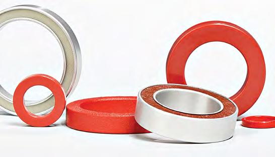
TOROIDS
Toroids are the least expensive ferrite shape. Available in a variety of sizes, outer diameters of 2.54 mm – 140 mm, toroids have good self-shielding properties. The fact that the core is a solid with no sections to assemble makes it a good choice if mechanical integrity is important in a high vibration environment. Toroid cores are available uncoated or with an epoxy, nylon or Parylene coating.
CORE MATERIALS
POWER
Magnetics R, P, F, T and L materials provide superior saturation, high temperature performance, low losses and product consistency.
T material is ideal for consistent performance over a wide temperature range. Applications for T include: Automotive, Electronic Lighting, Outdoor LCD Screens, Mobile Handheld Devices and AC adapters and chargers.
L material was formulated for high-frequency and high-temperature applications. L is designed for DC-DC converters, filters and power supplies that operate from 0.5 – 3.0 Mhz. Curie temperature is high for a ferrite material at 280˚C.
R material is an economical, low-loss choice for a broad range of applications.
P material offers similar properties to R material, but is more readily available in some sizes.
F material is an established material with a relatively high permeability and 210˚C Curie temperature.
Power Supplies, DC-DC Converters, Handheld Devices, High Power Control (gate drive) and EMI Filters are just a few of the applications that are typical for Magnetics ferrite power materials.
FILTER
Magnetics high permeability materials are engineered for optimum frequency and impedance performance in signal, choke and filter applications.
J and W materials offer high impedance for broadband transformers and are suitable for low-level power transformers.
J material is a medium perm, general-purpose material.
J’s properties are well suited both for EMI/RFI filtering and broadband transformers.
W material has set the industry standard for high perm materials. In filter applications, W perm has 20-50% more impedance below 1 MHz than J perm.
M material is Magnetics’ highest permeability material at 15,000μ. Applications for M include: EMI/RFI suppression filters, common mode chokes, signal processing, and broadband transformers.
LINEAR FILTERS AND SENSORS
Magnetics C, E and V materials offer excellent properties for low-level signal applications. These materials set the standard for high quality factor, long-term stability and precise and adjustable inductance. Applications for these materials include high Q filters, wideband transformers, pulse transformers and RLC tuned circuits.
Inductor Design
Ferrite E cores and pot cores offer the advantages of decreased cost and low core losses at high frequencies. For switching regulators, power materials are recommended because of their temperature and DC bias characteristics. By adding air gaps to these ferrite shapes, the cores can be used efficiently while avoiding saturation.
These core selection procedures simplify the design of inductors for switching regulator applications. One can determine the smallest core size, assuming a winding factor of 50% and wire current carrying capacity of 500 circular mils per ampere.
Only two parameters of the design applications must be known: (a) Inductance required with DC bias (b) DC current
1. Compute the product of LI² where:
L = inductance required with DC bias (millihenries) I = maximum DC output current + 1/2 AC Ripple
2. Locate the LI² value on the Ferrite Core Selector charts shown. Follow this coordinate up to the intersection with the first core size curve. Read the maximum nominal inductance, AL, on the Y-axis. This represents the smallest core size and maximum AL at which saturation will be avoided.
3. Any core size line that intersects the LI² coordinate represents a workable core for the inductor if the core’s AL value is less than the maximum value obtained on the chart.
4. Required inductance L, core size, and core nominal inductance (AL) are known. Calculate the number of turns using where L is in millihenries.
5. Example: If IMAX = 8 Amps; L, inductance required = 100 µHenries LI² = (0.100 mH) X (8² Amps) = 6.4 millijoules
6. There are many ferrite cores available that will support the energy required. Any core size that the LI² coordinate intersects can be used at the A L value shown on the chart.
7. Some choices based upon an LI² value of 6.4 millijoules are:
Pot core 43622 A L = 400 Double Slab 43622 A L = 250 PQ core 43220 A L = 300 E core 44317 A L = 250
8. For the following A L values the number of turns required is:
A L = 400, N = 16 A L = 300, N = 19 A L = 250, N = 20 Make sure the wire size chosen will support the current and fit into the core set.
(EER42)
(EER48)
(EER54)
(ETD49)
(ETD59)
Inductor Design
A - 40707 (EP7) 41010 (EP10) 41110 (RM4)
B - 41313 (EP13)
C - 41510 (RM5)
D 41717 (EP17)
E - 41812 (RM6)
F - 42316 (RM8)
G 42120 (EP20)
H - 42819 (RM10)
J - R43723 (RM12)
- 41203 B - 41707 C - 41808
- 42510 E - 43009 43515 F - 44317 G - 44033 H - 44011 44016 I - 44020 44022 44721 J - 45528 45530 47228 48020 45724 46016
- 46527 47133
49928
A - 41425 (EE, EI) 41434 (EE, EI)
B - 41805 (EE, EI) C - 42107 (EE, EI) D - 42216 (EE, EI)
E - 43208 (EE, EI) 43616 (EE, EI)
F - 43808 (EE, EI) G - 44008 (EE, EI)
- 44308 (EE, EI) 44310 (EE, EI)
- 45810 (EE, EI) J - 46410 (EE, EI)
- 49938 (EE)
Inductor Design
DC BIAS DATA — FOR GAPPED APPLICATIONS
NI = 0.80 x H x le Where
NI = maximum allowable ampere-turns
H = DC Bias level
le = core path length (cm)
The above curves are limit curves, up to which effective permeability remains constant. They show the maximum allowable DC bias, in ampere-turns, without a reduction in inductance. Beyond this level (see insert), inductance drops rapidly.
Example: How many ampere-turns can be supported by an R42213A315 pot core without a reduction in inductance value?
le = 3.12 cm µe = 125
Maximum allowable H = 25 Oersted (from the graph above)
NI (maximum) = 0.80 x H x le = 62.4 ampere-turns or (Using top scale, maximum allowable H = 20 A T/cm.)
NI (maximum) = A•T/cm x le = 20 x 3.12 = 62.4 A •T
Ae = effective cross sectional area (cm2)
AL = inductance/1,000 turns (mH)
µi = initial permeability
lg = gap length (cm)
Inductance falls off rapidly above the limit curve. The dashed lines illustrate the µe curve for individual gapped core sets.
Transformer Design
Magnetics offers two methods to select a ferrite core for a power application.
CORE SELECTION BY POWER HANDLING CAPACITY
The Power Chart characterizes the power handling capacity of each ferrite core based upon the frequency of operation, the circuit topology, the flux level selected, and the amount of power required by the circuit. If these four specifics are known, the core can be selected from the Power Chart on page 68.
CORE SELECTION BY WaAc PRODUCT
The power handling capacity of a transformer core can also be determined by its WaAc product, where Wa is the available core window area, and Ac is the effective core cross-sectional area. Using the equation shown below, calculate the WaAc product and then use the Area Product Distribution (WaAc) Chart to select the appropriate core.
FLUX DENSITY VS. FREQUENCY P MATERIAL
WaAc = Product of window area and core area (cm4)
Po = Power Out (watts)
Dcma = Current Density (cir. mils/amp) Current density can be selected depending upon the amount of heat rise allowed. 750 cir. mils/amp is conservative; 500 cir. mils is aggressive.
Bmax = Flux Density (gauss) selected based upon frequency of operation. Above 20 kHz, core losses increase. To operate ferrite cores at higher frequencies, it is necessary to operate the core flux levels lower than ± 2 kG. The Flux Density vs. Frequency chart shows the reduction in flux levels required to maintain 100 mW/cm³ core losses at various frequencies, with a maximum temperature rise of 25°C for a typical power material, Magnetics P material.
Ac = Core area in cm2 V = Voltage
ƒ = frequency (hertz) lp = Primary current
Kt = Topology constant ls = Secondary current (for a space factor of 0.4) Np = Number of turns on the primary NS = Number of turns on the secondary
TOPOLOGY CONSTANTS Kt
Forward converter = 0.0005
Half-bridge = 0.0014
Flyback = 0.00033 (single winding)
Push-Pull = 0.001
Full-bridge = 0.0014
Flyback = 0.00025 (multiple winding)
For individual cores, WaAc is listed in this catalog under “Magnetic Data.”
The WaAc formula was obtained from derivations in Chapter 7 of A. I. Pressman’s book, “Switching Power Supply Design. Choice of Bmax at various frequencies, Dcma and alternative transformer temperature rise calculations are also discussed in Chapter 7 of the Pressman book.
Once a core is chosen, the calculation of primary and secondary turns and wire size is readily accomplished.
KWa = NpAwp + NsAws
Where
Awp = primary wire area Aws = secondary wire area
Assume K = .4 for toroids; .6 for pot cores and E-U-I cores
Assume NpAwp = 1.1 NsAws to allow for losses and feedback winding
Typical Power Handling Chart
Typical Power Handling Chart
Ferrite Core selection listed by typical Power Handling Capabilities (Chart is for Power Ferrite Materials, F, P, R, L and T, Push-Pull Square wave operation)
Wattage values shown above are for push-pull converter design. De-rate by a factor of 3 or 4 for flyback. De-rate by a factor of 2 for feed-forward converter.
Example: For a feed-forward converter to be used at 300 watts select a core that is rated at 600 watts based on the converter topology.
Note: Assuming core loss to be approximately
B Levels used in this chart are:
Area Product Distribution (WaAc) Chart
Area Product Distribution (WaAc) Chart
Other Products from Magnetics

POWDER CORES
Powder cores are excellent as low loss inductors for switched-mode power supplies, switching regulators and noise filters. Most core types can be shipped immediately from stock.
Magnetics Kool Mμ® powder cores exhibit low losses at elevated frequencies. Kool Mμ is available in 7 permeabilities and a variety of core types for maximum flexibility. Toroids offer compact size and self-shielding. E cores, U cores, EQ cores, and LP cores afford lower cost of winding, use of foil windings or helical windings, and ease of fixturing. For very high current applications, very large cores and structures are available including toroids up to 165 mm, large E cores, U cores, stacked shapes, and blocks.
Magnetics Kool Mμ® MAX powder cores offer 50% better DC bias performance than standard Kool Mμ material. Available in 7 permeabilities from 14μ to 90μ including toroids, blocks, U cores and E cores.
Magnetics Kool Mμ® Hƒ powder cores are the best option for achieving superior efficiency in medium and high current power inductors and are available in 26μ, 40µ and 60μ.
Magnetics XFlux ® powder cores are made from 6.5% silicon iron powder for very high saturation flux density, comparable with High Flux. XFlux is available in 7 permeabilities from 19μ to 125μ and multiple shapes including toroids, E cores, block cores, EQ cores, LP cores, and EER cores.
Magnetics High Flux powder cores exhibit very high resistance to saturation at high current. High Flux is available in 7 permeabilities from 14μ to 160μ and over 30 sizes. Shapes include toroids, EQ cores, LP cores, and EER cores.
Magnetics Edge® powder cores are the best option for achieving smallest package size in high frequency, current-limited power inductors and are available in 5 permeabilities from 19μ to 125μ.
Magnetics Molypermalloy (MPP) powder cores have extremely low core losses, highest Q, and best temperature stability compared with other materials. Standard cores include either temperature stabilized (guaranteed flat as wide as -65°C to 125°C for stable operation) or standard stabilization. MPP toroidal cores are available in 10 permeabilities from 14μ to 550μ and sizes identical to High Flux.
TAPE WOUND CORES
Strip wound cores are made from high permeability magnetic strip alloys of nickel-iron (80% or 50% nickel), and silicon-iron. The alloys are known as Orthonol®, Permalloy 80, 48 Alloy and Magnesil®. Tape Wound Cores are produced as small as 0.438” OD in hundreds of sizes. For a wide range of frequency applications, materials are produced in thicknesses from ½ mil (0.013 mm) through 4 mils (0.102 mm). Cases are robust nylon and aluminum boxes, rated for 200°C continuous operation and 2,000 minimum voltage breakdown.
Tape wound cores are useful for both power and signal circuits in harsh environmental conditions where robust component operation is essential to achieve high reliability.
BOBBIN CORES
Bobbin cores are miniature tape cores made from ultrathin (0.000125” to 0.001” thick) strip material wound on nonmagnetic stainless steel bobbins. Bobbin cores are generally manufactured from Permalloy 80 and Orthonol®. Covered with protective caps and then epoxy coated, bobbin cores can be made as small as 0.05” ID and with strip widths down to 0.032”. Bobbin cores can switch from positive to negative saturation in a few microseconds or less, with very high peak impedance (relative permeability) while not saturated, making them ideal for analog logic elements, magnetometers, and pulse transformers.
Bobbin cores are also useful for analog counters, timers, magnetic sensors, and other analog circuits in harsh environmental conditions where robust and reliable operation is essential.
NANOCRYSTALLINE CORES
Nanocrystalline cores are made from amorphous metal which is annealed to create a uniform nanocrystalline microstructure. Sizes include toroids and split cores from 5 mm to 145 mm, and durable cases are available in polyester (<130°C) and rynite polyester (<155°C). Nanocrystalline cores are a choice solution for applications such as common mode chokes and current transformers as they exhibit high permeability, low power loss, and high saturation.
AMORPHOUS CORES
Amorphous cores are made from metallic glass materials with an amorphous atomic structure, which creates higher resistivity than nanocrystalline cores. Amorphous cores offer excellent frequency response and efficiency, and they are a choice solution for high frequency, low loss applications. Magnetics offers amorphous cut cores (C shape) from 51 mm to 131 mm, with toroids and split cores available upon request.
• Design Equations
• Area Product Distribution (WaAc) and Power Charts
• Product Datasheets
• Product Catalogs
• Design Software
• Distributor Stock Check
• Part Number Search
• Cross Reference Tool

