BACHELOR OF ENVIRONMENTS (ARCHITECTURE) UNIVERSITY OF MELBOURNE
MASTER OF ARCHITECTURE UNIVERSITY OF MELBOURNE
EDUCATION
Master of Architecture - University of Melbourne
2020-2021
Bachelor of Environments - University of Melbourne
2016-2019
Launceston Church Grammar School
2004-2014
EXPERIENCE
MGAO
MADDIE ARCHER ARCHITECTURAL GRADUATE

maddiearcher@hotmail.com
0417590799
My name is Maddie Archer, I graduated from my Master of Architecture course at the University of Melbourne at the end of 2021. For the past four years I have been working at Rothelowman. In this role I have worked across various stages of the design process gaining experience in design visualisation, town planning, and documentation in both Revit and Sketchup.
I have worked on a range of projects during this time including both commercial and multi-residential projects. This experience has been extremely helpful in improving my understanding of practice, and also my technical skills and knowledge. I have recently had more experience in small scale residential projects involving domcumentation in Revit as well as being the main contact for the client and consultants. I am excited to gain more experience in this area and develop my skills in residential project design and management.
I also have a special interest in heritage architecture and restoration work having grown up on a World Heritage Listed Site in Tasmania, surrounded by heritage buildings.
I am a very social person and an avid learner and I believe I have great communication and organisational skills. This helps me work well within teams both within my own workplace, and the larger teams beyond that.
Architectural Graduate
February 2023-May 2023
Rothelowman
Architectural Graduate
December 2021-December 2022
Architectural Assistant
January 2019-December 2021
• Feasibility/ Yield Studies in Revit
• Development of town planning reports
• Documentation and area/development schedule generation in Revit
• Exterior and interior 3D visualisations in Sketchup/ Enscape
Burlington Berries
Horticulture Hand 2014-2018
Charles St Pantry
Waitress 2015-2016
Brickendon Estate
Retail/Sales Assistant 2015
DESIGN SKILLS
Revit
Sketchup
Indesign
Photoshop
Illustrator
Enscape Rhino
AWARDS
Future Homes Student Competition 2020 Commhaus - First Prize
REFERENCES
Chris Exner
Associate Principal - Rothelowman
ChrisE@rothelowman.com.au
0438 733 007
Sarah Box Associate - Rothelowman
SarahB@rothelowman.com.au
0431 040 138
Ellie Harmsworth
Senior Architect - Conrad
Ellie.l.harmsworth@gmail.com
0422 461 492
Matt Goodman
MGAO
matt@mgao.com.au
01 04 05 02 03
GEORGE STREET
SYNTHESIS EMERALD TOWER
C O N T E N T S
REYNOLDS STREET COMMHAUS
GEORGE STREET
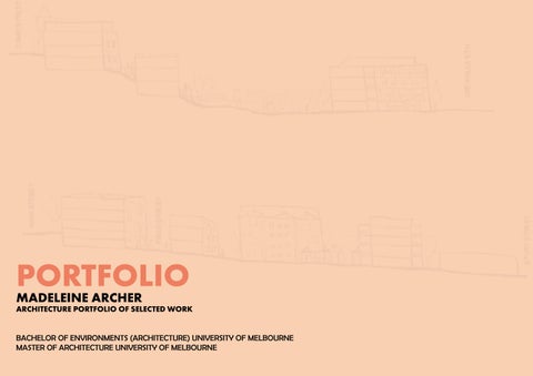
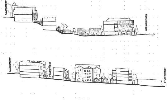
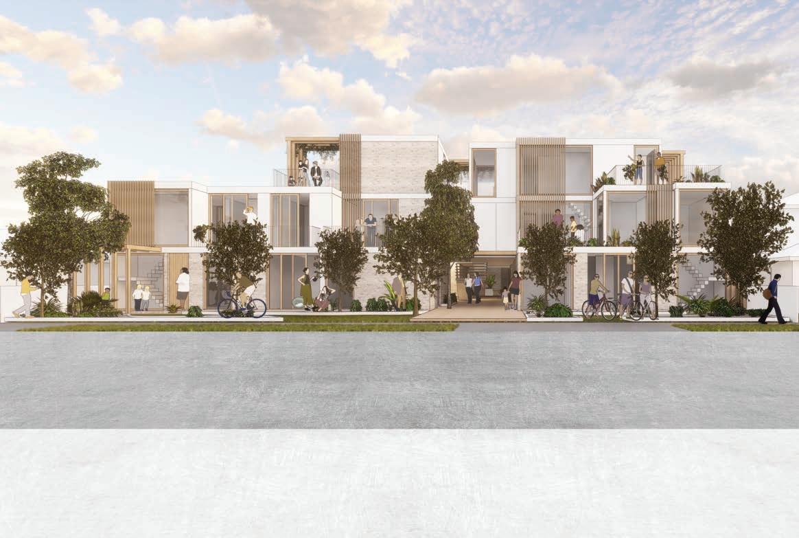
The George St project consists of replacing 5 existing residences with 35 townhouses in Sandringham, Victoria. The site is surrounded by commercial, industrial, aged-care, and residential properties. With this project, a main focus was creating an activated streetscape on George St, which is currently lacking in human scale form. The townhouses facing George St include front yards open to the street, and a public green space has been included with the retained established tree to encourage connections between neighbours and beyond, also resulting in a larger setback from the street across the site. The massing of the site was also considered, the George St facing houses were designed as 2-storey to create a softer feel to the street, while those further within the site being 3-storey. Though due to the incline over the site, the lower storey sinks into the ground towards southern boundary, meaning the impact on the neighbouring aged-care facility is reduced.


UP UP UP TITLE BOUNDARY 188° 00' 56" (49.446 m) TITLE BOUNDARY 188° 00' 56" (16.459 m) TITLE BOUNDARY 8° 00' 56" (49.446 m) TITLE BOUNDARY 8° 00' 56" (16.459 m) TITLE BOUNDARY 8° 00' 56" (16.675 m) T T E B O U N D 9 0 9 2 6 8 8 1 m 7 1 0 m TITLE BOUNDARY 7° 59' 30" (16.450 m) 97° 20' 26" (0.073 m) B O U N D A R Y 7 9 3 5 1 m TITLE B U D RY 16.3 3 m O N R 6 P E E P E P T E U D N N R C N R C O 3 ABERDEEN ROAD DOUBLE STOREY AGED CARE FACILITY P S W R S W R IT H P P N U N D A R Y 7 0 6 1 1 0 m O P S P S P S O G E O R G E S T R E E T PEDESTRIAN FOOTPATH PEDESTRIAN FOOTPATH 2 STORY APARTMENT BUILDING EXTG RL 40.422 EXTG RL 38.155 EXTG RL 36.731 EXTG RL 36.160 EXTG RL 35.511 EXTG RL 36.539 EXTG RL 37.923 EXTG RL 37.567 EXTG RL 38.200 HARD PAVING DRIVEWAY CARPARK HARD PAVING DRIVEWAY CARPARK LANDSCAPE GARDEN SCHOOL OVAL 11 HOLLOWAY RD SANDRINGHAM COLLEGE 10 - 12 CAMPUS GEORGE STREET 13 GEORGE STREET NEW CROSSOVER TPZ 9600 LOT 11 LOT 12 LOT 13 LOT 14 LOT 15 LOT 16 LOT 10 LOT 9 LOT 8 LOT 7 LOT 6 LOT 5 LOT 4 LOT 3 LOT 2 LOT 1 LOT 35 LOT 34 LOT 33 LOT 32 LOT 17 LOT 18 LOT 19 LOT 20 LOT 21 LOT 22 LOT 23 LOT 24 LOT 25 LOT 26 LOT 27 LOT 28 LOT 29 LOT 30 LOT 31 AAAAAAAAA J
C C C C E E E E E E SHARED MEWS SHARED MEWS SHARED MEWS PEDESTRIAN ACCESS B L O C K 3 B L O C K 1 B L O C K 2 B L O C K 4 RL 37.996 RL 37.778 RL 37.590 RL 37.402 RL 37.214 RL 37.026 RL 36.838 RL 36.650 RL 36.312 RL 38.075 RL 38.075 RL 38.095 RL 38.095 RL 38.100 RL 38.100 RL 38.100 RL 38.100 RL 37.875 RL 37.875 RL 37.562 RL 37.562 RL 37.250 RL 37.250 RL 36.940 RL 36.940 RL 36.625 RL 36.625 RL 36.375 RL 36.500 RL 36.500 RL 36.300 RL 36.300 RL 36.100 RL 36.100 PROPOSED DRAINAGE EASEMENT CONCRETE SLEEPER RETAINING WALL WM WM WM WM WM WM WM WM WM WM WM WM WM WM WM WM WM WM WM WM WM WM WM WM WM WM WM WM WM WM WM WM WM WM MAIN SWITCH ELEC PILLAR RWT RWT RWT RWT RWT RWT RWT RWT RWT RWT RWT RWT RWT RWT RWT NOT FOR CONSTRUCTION PRELIMINARY Brisbane, Melbourne, Sydney www.rothelowman.com.au Disclaimer Rothe Lowman Property Pty. Ltd. retains all common law, statutory law and other rights including copyright and intellectual property rights in respect of this document. The recipient indemnifies Rothe Lowman Property Pty against all claims resulting from use of this document for any purpose other than its intended use, unauthoriz changes or reuse of the document on other projects without the permission of Rothe Lowman Property Pty. Ltd. Under no circumstance shall transfer of this document be deemed sale or constitute transfer of the license to use this document. ABN 76 005 783 997 27/10/2022 5:08:40 PM Author 3-11 George Street, Sandringham George Dev Pty Ltd Overall Site Plan -Ground 3-11 George Street The following notes shall be read in conjunction with all design documents, schedules & specifications including but not limited to architectural, structural and services drawings and specifications, and any principal's project requirements documents relating to this project. All documents to be read in conjunction with & comply with all reports including but not limited to bldg surveyor, acoustics, fire & esd reports. All work shall comply with NCC/ relevant authority requirements and Australian Standards (AS.) Codes fo trades. Do not scale off this drawing. Contractor shall verify all dimensions on site. Contractor shall report any discrepancy in the documents to the architect for clarification prior to the affected work proceeding. Contractor to confirm setout with architect prior to construction. All levels are to australian height datum (AHD) u.n.o. All materials and fittings to be fixed in strict accordance with the manufacturers current specification and recommendation. Expansion, control or construction joints for all materials/systems to be provided in accordance with manufacturers instructions. Locations of joints to be confirmed on site with architect prior to installation. Refer to surveyors drawings check survey and detail drawing to locate and confirm all existing services, pipes poles, embankments, pits and like prior to commencing any work. Refer to civil eng dwgs for existing and new water, drainage design and associated site works design and detail. Refer to civil eng and landscape dwgs for a roadway, paving, surface, surfaced finished surface levels. Refer to the acoustic report for required acoustic specification details. All acoustic requirements to meet minimum ncc u.n.o. Refer window schedule and/or facade eng details for all glass, frame types and finishes etc. All dimensions to be verified prior to preparation of shop drawings and commencement of construction. Refer to elevations and/or facade engineer drawings for further finishes and panel setout information -confirm with architect prior to manufacture and/or installation. All exposed steel to be hot dipped galvanised, refe finishes schedule for any painting requirements. All silicon sealant to be colour matched to adjacent surface u.n.o. All door hardware to be fixed at 1050mm a.f.f.l. u.n.o. refer door schedule for door/frame details and size. All glazing to comply with current versions of AS 1288 and AS 2047. Ensure flush transition between different floor finishes, provide flush aluminium angle between different floor surfaces. Any services penetrating fire rated/ acoustic wall or slab are to be appropriately sealed to NCC/authority approved method/materials in accordance with minimum frl/acoustic/ fire engineering requirements u.n.o. Ceiling framing systems documented are indicative only Framing installation to comply with manufacturers recommendations & set out accordingly for design/documentation intent. Fire indexes of materials, linings and surface finishes to comply with C1.10 of NCC. All wall types including but not limited to linings and insulation is to be full height to underside of sla u.n.o. ensure stud gauge/centres is suitable for proposed installation accordance with manufacturers installation requirements. General Notes P127.10.22Preliminary Issue 237 6973 2700 90 3077 1031130 6000 BED GARAGE L'DRY BED ENS ENTRY 103 2900 2210 4100 100 1345 1595 7513 12443 7513 TL10 SFL 0.000 BIN 120L BIN 120L BIN 240L ENS WIR 820w 820w 720w TL10 REFER INTERIOR DESIGNER'S JXX DETAILS. REFER INTERIOR DESIGNER'S JXX DETAILS. BATHROOM TYPE XX DETAILS. 50mm HIGH RAMP THRESHOLD DETAIL AT INTERFACE. SECTIONAL GARAGE DOOR REFER TO INTERIOR REFER INTERIOR DESIGNER'S JXX DETAILS. HR A12 A12 A11 T2 A04.004 A04.004 BED BED BATH PDR DINING LIVING 3350 7890 3160 3100 2210 KITCHEN TF01 720w 720w 2660mmH 900mmW C/L A/C TERRACE REFER INTERIOR DESIGNER'S JXX DETAILS. TYPE BATHROOM TYPE XX DETAILS. REFER TO INTERIOR DESIGNER'S TYPE XX BATHROOM TYP XX DETAILS. REFER INTERIOR DESIGNER'S KITCHEN TYPE XX DETAILS. REFER TO INTERIOR DESIGNER'S JXX PLANTER BENCH TOP 4.350 TOP 4.350 TOP 4.950 A14 A16 A14 103 10724 103 5210 103 16190 SOLAR PANEL PARAPET PARAPET TOP 5.800 TOP 5.800 NOT PRELIMINARY Brisbane, www.rothelowman.com.au Scale: Project Project Drawing Client common copyright document. The recipient against any purpose changes the permission deemed Revisions Status 1 222003 3-11 Sandringham George Townhouse Ground, Plans 3-11 Sandringham The following design but not drawings requirements All documents all reports acoustics, All work requirements trades. Do not Contractor Contractor to the proceeding. Contractor All levels All materials with the recommendation. Expansion, materials/systems manufacturers confirmed Refer drawing poles, any work. Refer drainage detail. roadway, levels. Refer specification Refer glass, All dimensions drawings Refer further architect All exposed finishes All silicon All door door All glazing AS 2047. provide Any services are method/materials frl/acoustic/ Ceiling Framing recommendations design/documentation Fire indexes comply All wall insulation ensure requirements. General SCALE TYPE A_GROUND FLOOR PLAN SCALE TYPE A_FIRST FLOOR PLAN SCALE TYPE A_ROOF PLAN A/CAIR CONDITIONER UNIT AFFLABOVE FINISHED FLOOR LEVEL ALT ALTERNATE COLOUR SCHEME CLCLOTHES LINE EBELECTRIC DISTRIBUTION BOARD LLINEN LDYLAUNDRY -RWT AND SOLAR HEATED WATER SYSTEM TO CONNECTED T ALL ABBREVIATIONS PLNTPLANTER SLSKY LIGHT STSTORAGE WIRWALK ROBE SYMBOL LEGEND: FINISHED FLOOR LEVEL FFL 0.000 REFER TO INTERIOR FINISHES SCHEDULE FOR CARPET TYPE BATHROOM FLOOR TILE TLxx TIMBER FLOORING FINISH TYPE TMxx CPxx TOP OF PARAPET LEVEL TOP 0.000 BALUSTRADE TYPE HANDRAIL TYPE BALxx HRxx GENERAL ROOF TYPE RFxx BATHROOM TYPE BTxx LAUNDRY TYPE LMxx CFxx CONCRETE TYPE P127.10.22Preliminary AF02 AF01 GROUND SFL 0.000 LEVEL PARAPET SFL 6.700 BED BED DINING LIVING GARAGE ENTRY DESIGNER'S JXX FOR DETAILS. DESIGNER'S JXX FOR DETAILS. STAIRS BENCH BK01 RF01 AF01 NOT PRELIMINARY Brisbane, www.rothelowman.com.au Scale: Project Project Drawing Client Disclaimer common copyright document. The recipient against any purpose changes the permission deemed Revisions Status 1 222003 3-11 Sandringham George Townhouse Sections 3-11 Sandringham The following design but not drawings requirements All documents all reports acoustics, All work requirements trades. Do not Contractor Contractor to the proceeding. Contractor construction. All levels All materials with the recommendation. Expansion, materials/systems manufacturers confirmed Refer drawing poles, any work. Refer drainage detail. roadway, levels. Refer specification minimum Refer glass, All dimensions drawings Refer further architect All exposed finishes All silicon surface door All glazing AS 2047. provide Any services are frl/acoustic/ Ceiling Framing recommendations design/documentation Fire indexes comply All wall insulation ensure requirements. General A/CAIR CONDITIONER UNIT AFFLABOVE FINISHED FLOOR LEVEL BBROOM CUPBOARD CLCLOTHES LINE EBELECTRIC DISTRIBUTION BOARD LB LETTER BOX LDYLAUNDRY STORAGE ACHIEVED FOR EACH DWELLING -RWT AND SOLAR HEATED WATER SYSTEM TO CONNECTED T ALL ABBREVIATIONS PLNTPLANTER SLSKY LIGHT WIPWALK PANTRY WIRWALK ROBE SYMBOL LEGEND: FINISHED FLOOR LEVEL FFL 0.000 TOP 0.000 STRUCTURAL FLOOR LEVEL CONCRETE FINISH POWDER COATING METAL FINISH MFxx REFER MATERIAL SELECTIONS FOR DESCRIPTION AND COLOUR ROOF FINISH RFxx CFxx MASONRY FINISH TYPE CLADDING SYS. POWDER COATING FINISH CSxx EXTERNAL PAINT FINISH EPxx BKxx GLAZING TYPE GTxx TILING FINISH TLxx TIMBER FINISH BALUSTRADE TYPE BALxx TMxx ALL GLAZING GT01 UNLESS NOTED OTHERWISE ALT ALTERNATE COLOUR SCHEME GENERAL SCALE TYPE A_3D_VIEW 2 SCALE 50 A04.001 TYPE A-SECTION AA SCALE TYPE A_3D_VIEW 1 P127.10.22Preliminary
BBBBBBBBBBBBBB B+
PROPOSED SHADOWS
4.2 G E O R G E S T R E E T G E O R G E S T R E E T E G
PROPOSED SHADOWS -9AM PROPOSED SHADOWS -10AM PROPOSED SHADOWS -11AM PROPOSED SHADOWS -12PM PROPOSED SHADOWS -1PM PROPOSED SHADOWS -2PM PROPOSED SHADOWS -3PM
T
SHADOW STUDY DEPICTING CONDITIONS ON 22ND SEPTEMBER GEORGE STREET 30
PROPOSED SHADOWS -9AM PROPOSED SHADOWS -10AM PROPOSED SHADOWS PROPOSED SHADOWS -12PM PROPOSED SHADOWS -1PM PROPOSED SHADOWS -2PM PROPOSED SHADOWS -3PM P117.08.22Issue for Information Final Draft MD
Revisions Disclaimer Rothe Lowman Property Pty. Ltd. retains all common law, statutory law and other rights including copyright and intellectualproperty rights respect this document.The recipient indemnifies Rothe Lowman Property Pty. Ltd. against claims resulting from se of this document forany purpose other than its intended use, unauthorized changes reuse the document on other projects without the permission of Rothe Lowman Property Pty. Ltd. Under no circumstance shall transfer this document be deemed sale constitute transfer of the license use this document. ABN 76 005 783 997
05.08.22
1 500 SK04.01 ND 222003 3-11 George Street, Sandringham Shadows -Proposed 3-11 George Street Sandringham
G E O R G E S T R E E T 0 G E O R G E S T R E E T G E O R G E S T R E E T G E O R G E S T R E E T 3000 G E O R G E S T R E E T 000 PRELIMINARY Revisions Disclaimer Rothe Lowman Property Pty. Ltd. retains all common law, statutory law and other rights including copyright and intellectualproperty rights respect this document.The recipient indemnifies Rothe Lowman Property Pty. Ltd. against all claims resulting from use of this document forany purpose other than its intended use, unauthorized changes or reuse of the document on other projects without the permission of Rothe Lowman Property Pty. Ltd. Under no circumstance shall transfer of this document be deemed sale or constitute transfer of the license to use this document. ABN 76 005 783 997


Drawing No. Author Scale: @ A1 Project No Project Drawing Date 12/08/2022 10:58:28


T G E O R G E S T R E E T G E O R G E S T R E E T G E O R G E S T R E E T G E O R G E S T R E E T Brisbane, Melbourne, Sydney
05.08.22
Drawing No. Author Scale: A1 Project No Project Drawing Date 500 P1 SK04.01 ND 222003 3-11 George Street, Sandringham Shadows -Proposed 3-11 George Street Sandringham


Brisbane, Melbourne, Sydneywww.rothelowman.com.au SUBJECT SITE GEORGE STREET 3 ABERDEEN RD AGED CARE R R R G E O R G E S T R E E T G E O R G E S T R E E T G E O R G E S T R E E T G E O R G E S T R E E T Brisbane, Melbourne, Sydney www.rothelowman.com.au Disclaimer Rothe Lowman Property Pty. Ltd. retains all common law, statutory law and other rights including copyright and intellectualproperty rights respect this document.The recipient indemnifies Rothe Lowman Property Pty. Ltd. against claims resulting from this document forany purpose other than intended use, unauthorized changes or reuse the document other projects without the permission Rothe Lowman Property Pty. Ltd. Under no circumstance shall transfer this Drawing No. Scale: Project No Project Drawing 25/08/2022 2:47:10 PM 1 500 P1 SK04.01 ND 222003 3-11 George Street, Sandringham Shadows -Proposed 3-11 George Street Sandringham 05.08.22 PROPOSED SHADOWS -9AM PROPOSED SHADOWS -10AM PROPOSED SHADOWS -11AM PROPOSED SHADOWS -12PM PROPOSED SHADOWS -1PM PROPOSED SHADOWS -2PM PROPOSED SHADOWS -3PM 3000 G E O R G E S T R E E T R G E S T R E E T 000 G E O R G E S T R E E T 3000 G E O R G E S T R E E T G E O R G E S T R E PRELIMINARY Revisions Disclaimer Rothe Lowman Property Pty. Ltd. retains all common law, statutory law and other rights including copyright and intellectualproperty rights in respect o this document.The recipient indemnifies Rothe Lowman Property Pty. Ltd. against all claims resulting from se of this document forany purpose other than its intended use, unauthorized changes or reuse of the document on other projects without the permission of Rothe Lowman Property Pty. Ltd. Under no circumstance shall transfer of this document be deemed sale or constitute a transfer of the license to use this document. ABN 76 005 783 997 Drawing No. Author Scale: @ A1 Project No Project Drawing Date 12/08/2022 10:58:28 AM 1 : 500 SK04.01 ND 222003 3-11 George Street, Sandringham Shadows -Proposed 3-11 George Street Sandringham 05.08.22 PROPOSED SHADOWS -9AM PROPOSED SHADOWS -10AM PROPOSED SHADOWS -11AM PROPOSED SHADOWS -12PM PROPOSED SHADOWS -1PM PROPOSED SHADOWS -2PM PROPOSED SHADOWS -3PM PROPOSED SHADOWS 4.2 SHADOW STUDY DEPICTING CONDITIONS ON 22ND SEPTEMBER GEORGE STREET 30 G E O R G E S T R E E T G E O R G E S T R E E T G E O R G E S T R E E T O O Revisions Disclaimer Rothe Lowman Property Pty. Ltd. retains common law, statutory law and other rights including copyright and intellectualproperty rights respect document.The recipient indemnifies Rothe Lowman Pro this document forany purpose other than intended use, unauthorized changes reuse the document on other projects without the permission Rothe Lowman Property Pty. Ltd. Under no circumstance shall transfer this document deemed sale or constitute transfer the license to use this document. ABN 76 005 783 997 Drawing No. Project SK04.01 3-11 George Street, Sandringham Shadows -Proposed 3-11 George Street Sandringham 05.08.22 PROPOSED SHADOWS -9AM PROPOSED SHADOWS -10AM PROPOSED SHADOWS PROPOSED SHADOWS -12PM PROPOSED SHADOWS -1PM PROPOSED SHADOWS -2PM PROPOSED SHADOWS P117.08.22Issue for Information Final Draft MD 0 G E O R G E S T R E E T G E O R G E S T R E E T 0 G E O R G E S T R E E T 0 G E O R G E S T R E E T O PRELIMINARY Revisions Disclaimer Rothe Lowman Property Pty. Ltd. retains all common law, statutory law and other rights including copyright and intellectualproperty rights in respect document.The recipient indemnifies Rothe Lowman Property Pty. Ltd. against all claims resulting from se of this document forany purpose other than its intended use, unauthorized changes or reuse of the document on other projects without the permission of Rothe Lowman Property Pty. Ltd. Under no circumstance shall transfer of this document be deemed sale or constitute a transfer of the license to use this document. ABN 76 005 783 997 Scale: @ A1 Project Drawing 12/08/2022 10:58:28 AM 1 : 500 222003 3-11 George Street, Sandringham Shadows -Proposed 3-11 George Street Sandringham 05.08.22 PROPOSED SHADOWS -9AM PROPOSED SHADOWS -10AM PROPOSED PROPOSED SHADOWS -12PM PROPOSED SHADOWS -1PM PROPOSED SHADOWS -2PM PROPOSED
PROPOSED SHADOWS SHADOW STUDY DEPICTING CONDITIONS ON 22ND SEPTEMBER GEORGE STREET
4.2
The urban mews was a large focus in this project. We wanted the shared space to feel welcoming and connected, rather than just feel like a back alley. Overlooking from terraces and windows, as well as front door access forms an activated, passively surveillanced space. A difficulty arose in the project when we completed a shodow analysis and found the townhouses to the East were overshadowing the sunken terraces of the neighbouring apartment building that had just begun construction. Through pushing and pulling of the form and manipulation of the internal layout we were able to find a result that maintained the required spacials while ensuring we were maintaining adequate sunlight to the future neighbours.


LOT 17 TH TYPE LOT 18 TH TYPE LOT 19 TH TYPE B LOT 20 TH TYPE LOT 21 TH TYPE LOT 22 TH TYPE B LOT 23 TH TYPE LOT 24 TH TYPE LOT 25 TH TYPE B LOT 26 TH TYPE LOT 27 TH TYPE LOT 28 TH TYPE B LOT 29 TH TYPE LOT 30 TH TYPE LOT 31 TH TYPE B+ BK01 BK01 NGL @ BUILDING FACE NGL @ BUILDING FACE GT01 AF01 AF01 AF01 AF02 MF01 GT01 GT01 MF01 RL 36.375 RL 36.625 RL 36.940 RL 37.250 RL 37.562 RL 37.875 RL 38.100 RL 38.100 RL 38.050 FEATURE PROTRUDING DASHED ON ELEVATION RL 48.100 AF01 MF01 FEATURE PROTRUDING BRICK PATTERN EXTENT SHOWN DASHED ON ELEVATION LOT 31 TH TYPE B+ LOT 30 TH TYPE B LOT 29 TH TYPE LOT 28 TH TYPE B LOT 27 TH TYPE B LOT 26 TH TYPE LOT 25 TH TYPE B LOT 24 TH TYPE LOT 23 TH TYPE LOT 22 TH TYPE B LOT 21 TH TYPE LOT 20 TH TYPE LOT 19 TH TYPE B LOT 18 TH TYPE LOT 17 TH TYPE TITLE BOUNDARY RL 47.875 RL 47.562 RL 47.250 RL 46.940 RL 46.625 RL 46.375 GT01 MF01 NGL @ BUILDING FACE NGL @ BUILDING FACE HEIGHT TO NGL AF03 PT01 PT01 AF02 AF03 GT01 PT01 GT01 AF01 MF01 RL 42.331 RL 48.100 AF03 AF03 AF02 AF02 Brisbane, Melbourne, Sydney Disclaimer Rothe Lowman Property Pty. Ltd. retains all common law, statutory law and other rights including copyright and intellectual property rights in respect of this document. The recipient indemnifies Rothe Lowman Property Pty Ltd. against all claims resulting from use of this document for any purpose other than its intended use, unauthorized changes or reuse of the document on other projects without the permission of Rothe Lowman Property Pty. Ltd. Under no circumstance shall transfer of this document be deemed a sale or constitute transfer of the license to use this document. ABN 76 005 783 997 Revisions - SCALE 200 Part 2 East Elevation 1 - SCALE 200 Part 2 West Elevation 2 site landscape TITLE BOUNDARY 188° 00' 56" (49.446 m) TITLE BOUNDARY 188° 00' 56" (16.459 TITLE BOUNDARY 8° 00' 56" (49.446 m) TITLE BOUNDARY 00' 56" (16.459 TITLE BOUNDARY 00' 56" (16.675 m) TITLE BOUNDARY 7° 59' 30" (16.450 m) 97° 20' 26" (0.073 m) O OUND GEORGE STREET W W M N ABERDEEN ROAD DOUBLE STOREY AGED CARE FACILITY P GN PEDESTRIAN FOOTPATH PEDESTRIAN FOOTPATH O PRELIMINARY Brisbane, Melbourne, Sydney www.rothelowman.com.au Disclaimer Rothe Lowman Property Pty. Ltd. retains all common law, statutory law and other rights including copyright and intellectualproperty rights respect this document.The recipient indemnifies Rothe Lowman Property Pty. Ltd. against claims resulting from se of this document forany purpose other than intended use, unauthorized changes or reuse the document other projects without the permission Rothe Lowman Property Pty. Ltd. Under no circumstance shall transfer of this document be deemed sale constitute transfer of the license use this document. ABN 76 005 783 997 Drawing No. Author Scale: @ A1 Project No Project Drawing Date 1 200 SK03.04 IL 222003 3-11 George Street, Sandringham Site Plan -Blank 3-11 George Street Sandringham 08/08/22 Legend Secondary Landscape 2.4 Opportunities Setbacks from the street define areas for street frontage The area around the pedestrian link and existing tree create The perimeter of the site is softened by landscape Secondary landscape softens the shared vehicle and pedestrian access throughout the site. A raised level 1 Terrace Deck is used to soften the western interface and pick up the difference in height with the 3 STOREYS 3 STOREYS 2 STOREYS GEORGE STREET 14 8m 7.6m 5.4m 14m 7m 00' 56" (16.459 m) TITLE BOUNDARY 8° 00' 56" (16.675 m) 96 09 26 8 810 m 7 0 7 5 6 ( 1 9 7 0 m ) TITLE BOUNDARY 7° 59' 30" (16.450 m) 97° 20' 26" (0.073 m) T TLE BOUNDARY 277° 19 30 (58 128 m) T IT L E B O U N D A R Y 1 9 5 0 1 4 4 1 6 .3 9 3 m ) T I T L E B O U N D RA Y 1 8 7 4 6 3 0 ( 1 9 2 1 5 m ) O R G E S T R E E T D R I EV W A Y C R SO S VO E R D R V E W A Y C R O S S O V E R D R I V E W A Y C R O S S O V E R D R V E W A Y C R O S S O V E R E L P A D J A C E N T A P A R T M E N T B U I L D I N G U( N D E R C O N TS R U C T O N ) S E W E R P I T S E W E R P IT D P D P PEDESTRIAN FOOTPATH P O S P O S P O S
statutory law and other rights including copyright and intellectualproperty rights in respect of this claims resulting from use of this document forany purpose other than its intended use, Property Pty. Ltd. Under no circumstance shall transfer of this Drawing No. Author Scale: @ A1 Project No Date 1 : 200 SK03.04 IL 222003 Site Plan -Blank 08/08/22 LOT 1 TH TYPE LOT TH TYPE LOT TH TYPE A LOT TH TYPE A LOT 5 TH TYPE LOT TH TYPE A LOT 7 TH TYPE LOT TH TYPE A LOT TH TYPE LOT 10 TH TYPE PEDESTRIAN LINK SHARED MEWS RL 45.004 RL 43.462 BK01 AF01 MF01 GT01 NGL @ BUILDING FACE NGL @ BUILDING FACE AF01 GT01 MF01 FEATURE PROTRUDING BRICK PATTERN EXTENT SHOWN DASHED ON ELEVATION RL 37.325 RL 37.660 RL 37.800 RL 37.960 RL 38.400 RL 38.565 RL 38.725 RL 39.000 RL 39.125 RL 39.260 RL 39.465 LB LB GATE GATE LB GATE LB GATE LB GATE LB GATE GATE GATE GATE GATE LB LB LB LB NGL AT FENCE LINE NGL AT FENCE LINE ABOVE NGL MAX 1200 MAX 1200 MAX 1200 MAX 1200 MAX 1200 MAX 150 MAX 1200 MAX 1200 RL 44.896 RL 44.678 RL 44.490 RL 44.302 RL 44.114 RL 43.926 RL 43.738 RL 43.550 GEORGE ST NATURE STRIPFOOT PATH SETBACK LOT TYPE A TITLE BOUNDARY RL 45.004 BK01 AF01 MF01 GT01 OPEN BRICKWORK OVER CASEMENT WINDOW NGL @ BUILDING FACE NGL NGL 38.201 RL 38.100 MAX 1200 LOT 11 TYPE SETBACK FOOTPATHNATURE STRIP GEORGE ST TITLE BOUNDARY RL 43.462 BK01 CS01 GT01 H E IG H T T O N G @ B U IL D IN G F A C E 7 1 8 AF01 RL 36.100 RL 42.312 LOT TH TYPE LOT TH TYPE A LOT TH TYPE A LOT TH TYPE LOT TH TYPE A LOT 6 TH TYPE LOT TH TYPE A LOT 8 TH TYPE LOT TH TYPE A LOT 10 TH TYPE SHARED MEWS RL 45.004 AF01 TM01 NGL @ BUILDING FACE NGL @ BUILDING FACE MF01 GT01 MF01 BK01 AF01 GT01 TM01 RL 38.419 RL 38.261 RL 38.043 RL 37.855 RL 37.667 RL 37.479 RL 37.291 RL 37.103 RL 36.915 RL 36.727 RL 43.462 BK01 RL 44.896 RL 44.678 RL 44.490 RL 44.302 RL 44.114 RL 43.926 RL 43.738 RL 43.550 NOT FOR CONSTRUCTION PRELIMINARY Brisbane, Melbourne, Sydney www.rothelowman.com.au Drawing No. Revision Author Scale: @ A1 Project No Project Drawing Client Disclaimer Rothe Lowman Property Pty. Ltd. retains all common law, statutory law and other rights including copyright and intellectual property rights in respect of this document. The recipient indemnifies Rothe Lowman Property Pty Ltd. against all claims resulting from use of this document for any purpose other than its intended use, unauthorized changes or reuse of the document on other projects without the permission of Rothe Lowman Property Pty. Ltd. Under no circumstance shall transfer of this document be deemed a sale or constitute transfer of the license to use this document. ABN 76 005 783 997 Revisions Status Date 1 : 200 P1 A02.01 KC 222003 3-11 George Street, Sandringham George Dev Pty Ltd Overall Elevations Sheet 1 3-11 George Street Sandringham 06/03/13 The following notes shall be read in conjunction with all design documents, schedules specifications including but not limited to architectural, structural and services drawings and specifications, and any principal's project requirements documents relating to this project. All documents to be read in conjunction with & comply with all reports including but not limited to bldg surveyor, acoustics, fire & esd reports. All work shall comply with NCC/ relevant authority requirements and Australian Standards (AS.) Codes fo trades. Do not scale off this drawing. Contractor shall verify all dimensions on site. Contractor shall report any discrepancy in the documents to the architect for clarification prior to the affected work proceeding. Contractor to confirm setout with architect prior to construction. All levels are to australian height datum (AHD) u.n.o. All materials and fittings to be fixed in strict accordance with the manufacturers current specification and recommendation. Expansion, control or construction joints for all materials/systems to be provided in accordance with manufacturers instructions. Locations of joints to be confirmed on site with architect prior to installation. Refer to surveyors drawings check survey and detail drawing to locate and confirm all existing services, pipes poles, embankments, pits and like prior to commencing any work. Refer to civil eng dwgs for existing and new water, drainage design and associated site works design and detail. Refer to civil eng and landscape dwgs for a roadway, paving, surface, surfaced finished surface levels. Refer to the acoustic report for required acoustic specification & details. All acoustic requirements to meet minimum ncc u.n.o. Refer window schedule and/or facade eng details for all glass, frame types and finishes etc. All dimensions to be verified prior to preparation of shop drawings and commencement of construction. Refer to elevations and/or facade engineer drawings for further finishes and panel setout information -confirm with architect prior to manufacture and/or installation. All exposed steel to be hot dipped galvanised, refe finishes schedule for any painting requirements. All silicon sealant to be colour matched to adjacent surface u.n.o. All door hardware to be fixed at 1050mm a.f.f.l. u.n.o. refer door schedule for door/frame details and size. All glazing to comply with current versions of AS 1288 and AS 2047. Ensure flush transition between different floor finishes, provide flush aluminium angle between different floor surfaces. Any services penetrating a fire rated/ acoustic wall or slab are to be appropriately sealed to NCC/authority approved method/materials in accordance with minimum frl/acoustic/ fire engineering requirements u.n.o. Ceiling framing systems documented are indicative only Framing installation to comply with manufacturers recommendations & set out accordingly for design/documentation intent. Fire indexes of materials, linings and surface finishes to comply with C1.10 of NCC. All wall types including but not limited to linings and insulation is to be full height to underside of slab u.n.o. ensure stud gauge/centres is suitable for proposed installation in accordance with manufacturers installation requirements. General Notes SCALE 200 Part 1 East Elevation 1 SCALE 200 Part 1 North Elevation 3 SCALE 200 Part 1 South Elevation 4 4 SCALE 200 Part 1 West Elevation 2 GEORGE STREET MEWS 3 KEY PLAN 1 2 4 P127.10.22Preliminary Issue KC
Brisbane, Melbourne, Sydneywww.rothelowman.com.au
REYNOLDS STREET
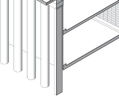
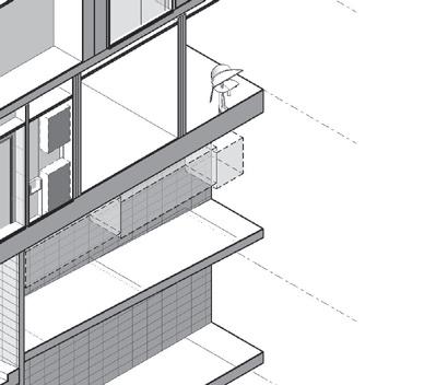
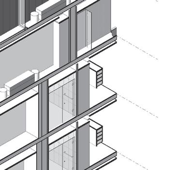
The Reynolds street project is an eight storey apartment building which contains 83 social housing dwellings, located in Hampton East, Victoria. Working alongside Housing Choices Australia (HCA), the aim of Reynolds street is to provide high quality, affordable and accessible housing. The design of the apartments will respond to the ‘Better Apartment Design Standards’ and the ‘Liveable Housing Australian Design Guidelines’ (silver standard) to achieve a NatHERS 7-star rating and Green Star 5-star AsBuilt rating.
The site is sloped, with a drop of approximately 2 metres from north-south. The site will be flattened before the basement begins excavation. Due to this, a lot of work has been done to work out the retention plan for the proposed building, to ensure the surrounding sites are protected through demolition, excavation and construction. Piles and capping beams have been located along the northern and eastern boundaries to retain the neighbouring site levels.
UP UP 3 4 5 6 7 B C D E F 2 1 T LE B UN A Y 8 9 00 4 37 m) TITLE BOUNDARY 0° 12' 30" (36.727 m) T TL BOU D Y m TITLE BOUNDARY 180° 12' 30" (34.407 m) T P T PIT GRATED PIT EASEMENT A 8 UG.11 ADAPT. TYPE 2D 1300 L02 L01 RG.03 CORRIDOR BASEMENT LID AND PAVEMENT SLAB TO SOUTH TO BE RESOLVED ONCE REVISED STRUCTURE COMES THROUGH A09.301 RG.01 AIRLOCK RG.05 OFFICE MEETING STORE RG.04 CORRIDOR LIGHTWELL UG07.D1 UG08.D1 UG06.D1 UG05.D1 UG06.D3 UG06.D2 A03.003 UG09.D1 UG09.D3 UG09.D2 UG10.D1 UG10.D2 UG10.D3 UG10.D4 UG11.D1 UG11.D2 UG11.D3 UG11.D4 UG12.D2 UG12.D3 UG12.D4 UG13.D1 UG13.D2 UG13.D3 UG13.D4 UG01.D2 UG01.D3 UG01.D4 UG03.D2 UG03.D3 UG04.D2 UG04.D3 UG04.D4 UG08.D2 UG08.D3 UG05.D2 UG05.D3 UG02.D2 UG02.D3 UG13.W1 UG13.W2 UG13.W3 UG01.W1 UG01.W2 UG01.W3 UG02.W1 UG02.W2 UG02.W3 UG03.W1 UG03.W2 UG03.W3 UG04.W1 UG04.W2 UG05.W1 UG05.W2 UG06.W1 UG06.W2 A03.001 A03.004 UG06.W4 UG04.W3 UG07.W1 UG07.W2 UG07.W3 UG10.W2 UG10.W3 UG11.W1 UG11.W2 UG11.W3 UG12.W1 UG12.W2 UG12.W3 MASTER BEDROOM MASTER BEDROOM BEDROOM RG02.D1 RG05.D1 RG04.D1 UG08.W1 UG08.W2 RB101.D1 UG06.W3 UG06.D4 UG01.D5 RG01.D1 RG01.D2 RG03.D1 RG03.D2 MAILBOXES R101.W1 RG03.W2 R102.W1 FT01 FT01 FT01 FT01 FT01 FT01 A/C A/C A/C A/C A/C A/C A/C A/C A/C A/C A/C A/C A/C DP DP KERB KERB TILT GARAGE DOOR UG13.D5 ADD GLASS SLIDER LAYOUT UNDER REVIEW LAYOUT UNDER REVIEW 2200 7900 8500 7850 4950 1220 7980 8495 8495 8495 8515 1780 RG05.W1 SFL 31.450 SFL 31.450 SFL 31.450 SFL 31.450 RG.02 STAIR 01 DEE P ANTNG ONE DE PPLAN NG ONE DEEP AN NG ON EE P N N ON MASTER BEDROOM BEDROOM MASTER BEDROOM MASTER BEDROOM MASTER BEDROOM MASTER BEDROOM MASTER BEDROOM MASTER BEDROOM MASTER BEDROOM MASTER BEDROOM BEDROOM BEDROOM MASTER BEDROOM BEDROOM MASTER BEDROOM BEDROOM PLANTING PLANTING PLANTING PLANTING PLANTING RAMP FROM BASEMENT 1 TO GROUND FLOOR UG.13 N/A TYPE 2A UG.02 N/A TYPE 1A UG.03 N/A TYPE 1A UG.04 ADAPT. TYPE 2C UG.05 SDA TYPE 1F UG.06 ADAPT. TYPE 1N UG.07 SDA TYPE 1P UG.08 SDA TYPE 1B UG.09 SDA TYPE 1C UG.10 ADAPT. TYPE 2S UG.12 SDA TYPE 2P UG.01 SDA TYPE 2B RG.02 LOBBY UG.02 N/A TYPE 1A RL 31.470 RL 31.470 DEEP PLANTING ZONE
A03.202 TERRACE TERRACE TERRACE TERRACE TERRACE TERRACE TERRACE TERRACE TERRACE TERRACE TERRACE TERRACE TERRACE TERRACE TERRACE 3004 732 1602 3467 SK05.00 SK05.00 A03.202 DEEP PLANTING ZONE 2062 NEW WESTERN FENCE TO FOLLOW EXISTING FENCE LINE. EXISTING NEIGHBOURING SHED TO BE RETAINED. REFER TO LAND SURVEY AND EXISTING CONDITIONS FOR EXACT LOCATION HIGHBURY AVENUE FIBRO SHED O N R N E M N 0 m A O R U D BOUNDARY FENCE 1700mm ABOVE GROUND LEVEL BOUNDARY FENCE 1700mm ABOVE GROUND LEVEL BOUNDARY FENCE 1700mm ABOVE GROUND LEVEL TIMBER PALING FENCE WITH ADDITIONAL RETAINING WALL AT TERRACES -MIN 1800mm ABOVE NATURAL GROUND D EE P P L A N T N G Z N E 3500 3131 3116 NOT FOR CONSTRUCTION PRELIMINARY Brisbane, Melbourne, Sydney www.rothelowman.com.au Drawing No. Revision Author Scale: @ A1 Project No Project Drawing Client Disclaimer Rothe Lowman Property Pty. Ltd. retains all common law, statutory law and other rights including copyright and intellectual property rights respect of this document. The recipient indemnifies Rothe Lowman Property Pty. Ltd. against all claims resulting from use of this document for any purpose other than its intended use, unauthorized changes or reuse of the document on other projects without the permission of Rothe Lowman Property Pty. Ltd. Under no circumstance shall transfer of this document be deemed a sale or constitute transfer of the license to use this document. ABN 76 005 783 997 Revisions Status Date 1 : 100 11/25/2022 5:20:10 PM P4 A01.003 SC 220041 1-5 Reynolds St CasUrban Developments General Arrangement Plan Ground 1-5 Reynolds St. Hampton East 25/11/22 The following notes shall be read in conjunction with all design documents, schedules & specifications including but not limited to architectural, structural and services drawings and specifications, and any principal's project requirements documents relating to this project. All documents to be read in conjunction with & comply with all reports including but not limited to bldg surveyor, acoustics, fire esd reports. All work shall comply with NCC/ relevant authority requirements and Australian Standards (AS.) Codes for trades. Do not scale off this drawing. Contractor shall verify all dimensions on site. Contractor shall report any discrepancy in the documents to the architect for clarification prior to the affected work proceeding. Contractor to confirm setout with architect prior to construction. All levels are to australian height datum (AHD) u.n.o. All materials and fittings to be fixed in strict accordance with the manufacturers current specification and recommendation. Expansion, control or construction joints for all materials/systems to be provided in accordance with manufacturers instructions. Locations of joints to be confirmed on site with architect prior to installation. Refer to surveyors drawings check survey and detail drawing to locate and confirm all existing services, pipes poles, embankments, pits and like prior to commencing any work. Refer to civil eng dwgs for existing and new water, drainage design and associated site works design and detail. Refer to civil eng and landscape dwgs for all roadway, paving, surface, surfaced finished surface levels. Refer to the acoustic report for required acoustic specification & details. All acoustic requirements to meet minimum ncc u.n.o. Refer window schedule and/or facade eng details for all glass, frame types and finishes etc. All dimensions to be verified prior to preparation of shop drawings and commencement of construction. Refer to elevations and/or facade engineer drawings for further finishes and panel setout information -confirm with architect prior to manufacture and/or installation. All exposed steel to be hot dipped galvanised, refer finishes schedule for any painting requirements. All silicon sealant to be colour matched to adjacent surface u.n.o. All door hardware to be fixed at 1050mm a.f.f.l. u.n.o. refer door schedule for door/frame details and size. All glazing to comply with current versions of AS 1288 and AS 2047. Ensure flush transition between different floor finishes, provide flush aluminium angle between different floor surfaces. Any services penetrating a fire rated/ acoustic wall or slab are to be appropriately sealed to NCC/authority approved method/materials in accordance with minimum frl/acoustic/ fire engineering requirements u.n.o. Ceiling framing systems documented are indicative only. Framing installation to comply with manufacturers recommendations & set out accordingly for design/documentation intent. Fire indexes of materials, linings and surface finishes to comply with C1.10 NCC. All wall types including but not limited to linings and insulation is to be full height to underside of slab u.n.o. ensure stud gauge/centres suitable for proposed installation in accordance with manufacturers installation requirements. General Notes P114.10.22PRELIM STRUCTURAL REVIEW SC P211.11.22PRELIMINARY SC P324.11.22NORTH & WEST FENCE AMENDMENTS SC P425.11.22FOR COORDINATION SC A/CAIR CONDITIONING CONDENSER UNIT BAL BALUSTRADE BG BOX GUTTER BJ BUTT JOINT BOL. BOLLARD BR BIKE RACK COL.COLUMN TO ENGINEERS DETAILS CJ CONTROL JOINT COMMSCOMMUNICATIONS BOARD REFER TO CONSULTANTS DRAWINGS CWM COLD WATER METER DPDOWNPIPES ELECELECTRICAL METERS REFER TO CONSULTANTS DRAWINGS PS01 PRIVACY SCREEN TYPE 01 RWH RAIN WATER HEAD RWO RAIN WATER OUTLET SUMP S/A SUPPLY AIR SBJ SILICON BUTT JOINT SD SPOON DRAIN SK SKYLIGHT -SOLATUBE STRSTORE TI TACTILE INDICATOR UNO UNLESS NOTED OTHERWISE WMTR WATER METERS REFER TO CONSULTANTS DRAWINGS NOTE:TO BE READ IN CONJUNCTION WITH INTERNAL AND EXTERNAL FINISHES SCHEDULE ABBREVIATIONS: F.E.FIRE EXTINGUSHER F.F.FINISHED FACE FHFIRE HYDRANT FHRFIRE HOSE REEL FIPFIRE INDICATOR PANEL FW FLOOR WASTE HRHANDRAIL LLOUVRE MSB MAIN SWITCHBOARD NGLNATURAL GROUND LEVEL OFOVER FLOW PJ PANEL JOINT SYMBOL LEGEND GENERAL WALL TYPE WPxx APPLIED FINISH TYPE AFxx BLOCKWORK/BRICK FINISH TYPE BKxx CONCRETE FINISH TYPE CFxx CLADDING SYSTEM TYPE CSxx GLAZING TYPE GTxx METAL CLADDING TYPE MCxx METAL FINISH TYPE MFxx ROOF FINISH TYPE RFxx TILE TYPE TLxx TIMBER FINISH TYPE TMxx NOTE: ALL APARTMENT INTERNAL DRYWALLS TO BE WALL TYPE WP01 UNLESS OTHERWISE NOTED REFER TO MATERIAL SELECTIONS FOR DESCRIPTION AND COLOUR MATERIAL TAG xxxx FW FLOOR WASTE PLANTER DRAIN DRAIN FINISHES PD 4 6 B C D E F 2 1 m) OUN TTEB UN A Y 5 6 ) EASEMENT A 8 A03.110 A03.110 A05.002 L02 L01 U1.09 ADAPT. TYPE 3D LIGHTWELL R1.01 CORRIDOR BT02 BT02 TOW 35.750 TOW 35.750 A/C A/C A/C A/C O/F O/F O/F O/F O/F ENGINEER DP DP DP DP DP DP DP DP DP A09.301 U112.D1 U112.W1 U112.W4 U112.W2 U112.D5 U101.D2 U101.D3 U101.D4 U101.W4 TBC U102.D3 U102.D2 U102.W4 U102.W1 U103.W1 U103.D3 U103.D2 U103.W4 TBC U104.W1 U104.W3 U104.D3 U105.W1 U105.W3 U105.W4 U105.D3 U106.D4 U106.D2 U106.W1 U106.W3 U107.D5 U107.W3 U107.D2 U107.W4 U108.D3 U108.W1 U108.W2 U108.W3 U109.D2 U109.W1 U109.W2 U109.D5 U109.W5 U109.W4 U110.D1 U110.D3 U110.D4 U110.W1 U110.W2 R102.D1 U111.D2 U111.D4 U111.W1 U111.W4 PROPOSED STRUCTURE INDICATED IN A03.003 A03.004 R101.W1 SFL 34.570 R101.W2 R1.02 STAIR 01 U1.01 ADAPT. TYPE 2F U1.12 ADAPT. TYPE 2E U1.02 N/A TYPE 1K U1.03 N/A TYPE 1K U1.04 ADAPT. TYPE 2G U1.05 ADAPT. TYPE 2H U1.06 ADAPT. TYPE 2I U1.07 N/A TYPE 2J U1.08 ADAPT. TYPE 2K U1.10 ADAPT. TYPE 2L U1.11 ADAPT. TYPE 2R MASTER BEDROOM BEDROOM BEDROOM BEDROOM MASTER BEDROOM BEDROOM BEDROOM MASTER MASTER BEDROOM MASTER BEDROOM MASTER BEDROOM MASTER BEDROOM BEDROOM BEDROOM BEDROOM BEDROOM VOID BELOW DT P NTNGZO TERRACE TERRACE TERRACE TERRACE TERRACE TERRACE SK05.00 SK05.00 A03.202 A/CAIR CONDITIONING CONDENSER UNIT BAL BALUSTRADE BJ BUTT JOINT BOL. BOLLARD BR BIKE RACK COMMSCOMMUNICATIONS BOARD REFER TO CONSULTANTS DRAWINGS CWM COLD WATER METER DPDOWNPIPES PS01 PRIVACY SCREEN TYPE 01 RWH RAIN WATER HEAD SUMP S/A SUPPLY AIR SBJ SILICON BUTT JOINT STRSTORE TACTILE INDICATOR UNO UNLESS NOTED OTHERWISE CONSULTANTS DRAWINGS NOTE:TO BE READ CONJUNCTION WITH ABBREVIATIONS: F.E.FIRE EXTINGUSHER F.F.FINISHED FACE FHRFIRE HOSE REEL FIPFIRE INDICATOR PANEL FW FLOOR WASTE MSB MAIN SWITCHBOARD NGLNATURAL GROUND LEVEL OFOVER FLOW SYMBOL LEGEND WALL TYPE WPxx APPLIED FINISH TYPE AFxx BLOCKWORK/BRICK FINISH TYPE BKxx CONCRETE FINISH TYPE CFxx CLADDING SYSTEM TYPE CSxx GLAZING TYPE GTxx METAL FINISH TYPE MFxx ROOF FINISH TYPE RFxx TILE TYPE TLxx TIMBER FINISH TYPE TMxx NOTE: ALL APARTMENT INTERNAL DRYWALLS TO BE WALL TYPE WP01 MATERIAL TAG FW TOO SMALL 4 6 B C D E F 2 1 m) O TEB UN A Y 5 6 ) EASEMENT A 8 A03.102 A03.103 R6.04 COMMUNAL DINING R6.03 COMMUNAL KITCHEN R6.05 ACCESS. WC R6.06 COMMUNAL TERRACE L02 L01 R6.02 STAIR 01 L6 & EASTERN FACADE TO BE METAL CLAD. INDICATE EXTENT OF STRUCTURAL PRECAST, IF REQUIRED PROPOSED STRUCTURE INDICATED IN A03.003 A03.002 A03.001 A03.004 BEDROOM DP BT01 DP DP DP DP A/C A/C BEDROOM U601.D5 U601.W4 U601.W1 U602.W3 U603.D1 U603.W2 U603.W4 U603.W5 U603.D2 U603.D3 U604.D1 U604.W1 U604.W3 U605.D1 U605.W1 U605.W3 U605.W4 R605.D1 U606.D4 U606.W3 U606.W5 U607.D1 U607.W1 U607.W4 R602.D1 U607.D2 U607.D3 U607.D5 TERRACE TERRACE TERRACE TERRACE TERRACE TERRACE U605.D2 U606.D2 LIGHTWELL TOW 51.150 TOW 51.150 TOW 51.150 1220 7980 8495 8495 8495 8515 1780 R6.01 CORRIDOR SFL 50.050 R601.W2 SFL 50.050 SFL 50.050 SFL 50.050 TOW 51.150 TOW 51.150 TOW 51.150 SFL 49.950 U6.07 ADAPT. TYPE 2E U6.01 ADAPT. TYPE 3E U6.02 ADAPT. TYPE 1G U6.04 ADAPT. TYPE 2H U6.06 ADAPT. TYPE 2R U6.03 ADAPT. TYPE 1L U6.05 ADAPT. TYPE 2I1 BEDROOM BEDROOM MASTER MASTER BEDROOM MASTER MASTER BEDROOM MASTER BEDROOM DT P NTNGZO A/CAIR CONDITIONING CONDENSER UNIT BG BOX GUTTER BJ BUTT JOINT BOL. BOLLARD CJ CONTROL JOINT COMMSCOMMUNICATIONS BOARD REFER TO CONSULTANTS DRAWINGS CWM COLD WATER METER ELECELECTRICAL METERS REFER TO CONSULTANTS DRAWINGS PS01 PRIVACY SCREEN TYPE 01 RWO RAIN WATER OUTLET SUMP S/A SUPPLY AIR SK SKYLIGHT -SOLATUBE STRSTORE TACTILE INDICATOR WMTR WATER METERS REFER TO CONSULTANTS DRAWINGS INTERNAL AND EXTERNAL FINISHES SCHEDULE ABBREVIATIONS: F.E.FIRE EXTINGUSHER FHFIRE HYDRANT FHRFIRE HOSE REEL FIPFIRE INDICATOR PANEL LLOUVRE MSB MAIN SWITCHBOARD NGLNATURAL GROUND LEVEL PJ PANEL JOINT SYMBOL LEGEND GENERAL APPLIED FINISH TYPE AFxx BLOCKWORK/BRICK FINISH TYPE BKxx CONCRETE FINISH TYPE CFxx CLADDING SYSTEM TYPE CSxx GLAZING TYPE GTxx METAL FINISH TYPE MFxx UNLESS OTHERWISE NOTED DESCRIPTION AND COLOUR MATERIAL TAG xxxx FW FLOOR WASTE PLANTER DRAIN DRAIN FINISHES GROUND FLOOR PLAN LEVEL 1 PLAN LEVEL 6 PLAN
DEEPPLANTNGZONE
Ground SFL 31.450 Level 3 SFL 40.750 3 4 5 6 7 Level 1 SFL 34.550 Level 2 SFL 37.650 Level 4 SFL 43.850 Level 5 SFL 46.950 2 Roof SFL 56.250 1 8 Level 6 SFL 50.050 Level 7 SFL 53.150 SUBJECT SITE 1-5 REYNOLDS STREET LANEWAY TITLE BOUNDARY AHD 41.850 AHD 41.050 MC03 VEHICLE ENTRY TILT DOOR MC02 MC01 AF02 PEDESTRIAN ENTRY CORE OVERRUN PLANT SCREEN GT01 GT01 GT01 GT01 4x VISITOR BIKES AHD 29.860 AHD 30.180 AHD 31.850 GT01 AF02 AHD 46.950 CF01 GT01 MC01 GT01 MC03 GT01 GT01 CF01 CF01 CF01 CF01 CF01 GT01 MF01 MF01 AHD 58.650 AHD 60.050 GT01 MC03 GT01 MC03 GT01 PERGOLA STRUCTURE MC02 MC02 GT01 GT01 GT01 AF02 CF01 CF01 GT01 GT01 GT01 AF02 AF02 MC01 AF02 MC01 MF01 TITLE BOUNDARY TITLE BOUNDARY 2000 1780 8515 8495 8495 8495 7980 1220 BOOSTERS NOT FOR CONSTRUCTION PRELIMINARY Drawing No. Revision Author Scale: @ A1 Project No Project Drawing Client Disclaimer Rothe Lowman Property Pty. Ltd. retains all common law, statutory law and other rights including copyright and intellectual property rights in respect of this document. The recipient indemnifies Rothe Lowman Property Pty. Ltd. against all claims resulting from use of this document for any purpose other than its intended use, unauthorized changes or reuse of the document on other projects without the permission of Rothe Lowman Property Pty. Ltd. Under no circumstance shall transfer of this document be deemed a sale or constitute transfer of the license to use this document. ABN 76 005 783 997 Revisions Status Date 1 100 P2 A03.001 SC 220041 1-5 Reynolds St CasUrban Developments South Elevation 1-5 Reynolds St. Hampton East 25/11/22 drawings and specifications, and any principal's project requirements documents relating to this project. All documents to be read in conjunction with comply with all reports including but not limited to bldg surveyor, acoustics, fire & esd reports. All work shall comply with NCC/ relevant authority requirements and Australian Standards (AS.) Codes for trades. Do not scale off this drawing. Contractor shall verify all dimensions on site. Contractor shall report any discrepancy the documents to the architect for clarification prior to the affected work proceeding. Contractor to confirm setout with architect prior to construction. All levels are to australian height datum (AHD) u.n.o. All materials and fittings to be fixed strict accordance with the manufacturers current specification and recommendation. Expansion, control or construction joints for all materials/systems be provided accordance with manufacturers instructions. Locations of joints be confirmed on site with architect prior to installation. Refer to surveyors drawings check survey and detail drawing to locate and confirm all existing services, pipes poles, embankments, pits and like prior to commencing any work. Refer to civil eng dwgs for existing and new water, drainage design and associated site works design and detail. Refer to civil eng and landscape dwgs for all roadway, paving, surface, surfaced finished surface levels. Refer to the acoustic report for required acoustic specification & details. All acoustic requirements to meet minimum ncc u.n.o. Refer window schedule and/or facade eng details for all glass, frame types and finishes etc. All dimensions to be verified prior to preparation shop drawings and commencement of construction. Refer to elevations and/or facade engineer drawings for further finishes and panel setout information -confirm with architect prior to manufacture and/or installation. All exposed steel to be hot dipped galvanised, refer finishes schedule for any painting requirements. All silicon sealant to be colour matched to adjacent surface u.n.o. All door hardware to be fixed at 1050mm a.f.f.l. u.n.o. refer door schedule for door/frame details and size. All glazing to comply with current versions of AS 1288 and AS 2047. Ensure flush transition between different floor finishes, provide flush aluminium angle between different floor surfaces. Any services penetrating a fire rated/ acoustic wall or slab are to be appropriately sealed to NCC/authority approved method/materials in accordance with minimum frl/acoustic/ fire engineering requirements u.n.o. Ceiling framing systems documented are indicative only. Framing installation to comply with manufacturers recommendations & set out accordingly for design/documentation intent. Fire indexes of materials, linings and surface finishes to comply with C1.10 of NCC. All wall types including but not limited to linings and insulation is to be full height to underside of slab u.n.o. ensure stud gauge/centres is suitable for proposed installation in accordance with manufacturers installation requirements. Legend EP - ELECTRICAL POLE EX. XO - EXISTING CROSSOVER FNC- 2100H FENCE HYD - HYDRANT HW- HABITABLE WINDOW LP - LIGHT POLE OBS- OBSCURED WINDOW OSD- ON-SITE DETENTION TANK RL- EQUALS AHD PIT- SERVICE PIT POS- PRIVATE OPEN SPACE PS - 1700H PRIVACY SCREEN SIGN - STREET SIGN - TERRACE W- NON-HABITABLE WINDOW XO - CROSSOVER MATERIALS AF01 Applied Finish -Warm White AF02 Applied Finish -Dark Grey CF01 Concrete Finish -Warm White CF02 Concrete Finish -Dark Grey MF01 Metal Finish -Dark Grey NOTE: ALL GLAZING GT01 -CLEAR GLASS, UNLESS OTHERWISE NOTED. LEGEND TO BE READ IN CONJUNCTION WITH INTERNAL AND EXTERNAL FINISHES SCHEDULE. GT01 Glass Type -Clear GT02 Glass Type -Obscured MC01 Metal Cladding -Dark Grey Vertical Seam MC02 Metal Cladding -Dark Grey MC03 Metal Cladding -Dark Grey Vertical Battens NOTE: •Glazing to achieve sound insulation rating of 30 dB Rw min. •Fixed elements of the building facade to achieve sound insulation of 40 dB Rw min. P111.11.22PRELIMINARY SC P225.11.22FOR COORDINATION SC Ground SFL 31.450 Level 3 SFL 40.750 3 4 5 6 7 Level 1 SFL 34.550 Level 2 SFL 37.650 Level 4 SFL 43.850 Level 5 SFL 46.950 2 Roof SFL 56.250 1 8 Level 6 SFL 50.050 Level 7 SFL 53.150 AHD 31.400 AHD 33.300 TWO STOREY COMMERCIAL 862 NEPEAN HIGHWAY LANEWAY SUBJECT SITE 1-5 REYNOLDS STREET SINGLE STOREY RESIDENTIAL HIGHBURY AVENUE TITLE BOUNDARY AHD 35.750 CORE OVERRUN 1.8m PLANT SCREEN GT02 MC01 MF01 GT01 CF01 CF01 CF01 OBS OBS MIN. 1700H NEW FENCE SHOWN DASHED IN FOREGROUND POS FOREGROUND HIGHBURY ST PRIVATE OPEN SPACE SHOWN BEYOND FNC FNC FNC FNC FNC GT01 GT01 GT01 GT01 GT01 MC03 HEIGHT ABOVE NGL 3100 3100 3100 3100 3100 3100 3100 3100 CF01 MF01 CF01 CF01 MF01 GT01 GT01 GT01 GT01 GT01 GT01 GT01 GT01 MC01 GT01 GT01 GT01 MC01 GT01 CF01 CF01 CF01 AHD 58.650 AHD 60.050 AF02 AF02 GT02 GT01 GT01 GT01 PERGOLA STRUCTURE MC01 GT01 GT01 GT01 GT01 GT01 GT01 GT01 GT01 GT01 GT01 MF01 MC02 MC02 MC02 MC02 MC02 MF01 MC01 MC03 CF01 GT01 MC03 MC01 U702.W3 U702.W2 U702.W1 U701.W3 U701.W2 U701.W1 U707.W4 U707.W3 U707.W2 GT01 20001780 8515 8495 8495 8495 7980 1220 GT01 GT01 GT01 GT01 GT01 GT01 GT01 GT01 GT01 GT01 GT01 GT01 GT01 GT01 GT01 GT01 GT01 GT01 GT01 GT01 GT01 GT01 GT01 GT01 GT01 GT01 GT01 GT01 GT01 GT01 GT01 GT01 GT01 GT01 GT01 GT01 GT01 GT01 GT01 GT01 GT01 GT01 GT01 GT01 GT01 GT01 GT01 GT01 GT01 GT01 GT01 GT01 GT01 GT01 GT01 GT01 GT01 GT01 GT01 GT01 GT01 GT01 GT01 GT01 GT01 GT01 GT01 GT01 GT01 GT01 MC03 GT01 GT01 GT01 GT01 U601.W4 U601.W2 U601.W1 U607.W4 U607.W2 U607.W1 U606.W5 U606.W3 U606.W2 U501.W5 U501.W4 U501.W2 U501.W1 U510.W4 U510.W2 U505.W4 U509.W4 U509.W2 U506.W4 U508.W6 U508.W4 U508.W3 U409.W4 U409.W3 U409.W5 U410.W1 U410.W2 U410.W4 U411.W1 U411.W2 U411.W4 U401.W1 U401.W2 U401.W4 U401.W5 U301.W5 U301.W4 U301.W2 U301.W1 U311.W4 U311.W2 U311.W1 U310.W4 U310.W2 U310.W1 U309.W5 U309.W4 U309.W3 U202.W1 U201.W4 U101.W4 U102.W1 UG02.W1 UG01.W3 UG01.W2 U101.W2 U101.W1 U201.W2 U204.W4 U212.W4 U112.W4 UG13.W3 UG13.W2 U112.W2 U212.W2 U212.W1 U112.W1 UG13.W1 UG12.W3 U111.W4 U211.W4 U109.W5 U209.W4 U210.W1 UG10.W2 U109.W4 UG10.W3 UG11.W2 UG11.W1 UG11.W3 UG12.W1 UG12.W2 U110.W3 U111.W1 U111.W2 U211.W2 U110.W2 U210.W4 U210.W2 U209.W3 U110.W1 NOT FOR CONSTRUCTION PRELIMINARY Brisbane, Melbourne, Sydney www.rothelowman.com.au Project Drawing Client Disclaimer Rothe Lowman Property Pty. Ltd. retains all common law, statutory law and other rights including copyright and intellectual property rights in respect of this document. The recipient indemnifies Rothe Lowman Property Pty. Ltd. against all claims resulting from use of this document for any purpose other than its intended use, unauthorized changes or reuse of the document on other projects without the permission of Rothe Lowman Property Pty. Ltd. Under no circumstance shall transfer of this document be deemed a sale or constitute transfer of the license to use this document. ABN 76 005 783 997 Revisions Status 1-5 Reynolds St CasUrban Developments North Elevation 1-5 Reynolds St. Hampton East The following notes shall be read in conjunction with all design documents, schedules & specifications including but not limited to architectural, structural and services drawings and specifications, and any principal's project requirements documents relating to this project. All documents to be read in conjunction with comply with all reports including but not limited to bldg surveyor, acoustics, fire & esd reports. All work shall comply with NCC/ relevant authority requirements and Australian Standards (AS.) Codes for trades. Do not scale off this drawing. Contractor shall verify all dimensions on site. Contractor shall report any discrepancy the documents to the architect for clarification prior to the affected work proceeding. Contractor to confirm setout with architect prior to construction. All levels are to australian height datum (AHD) u.n.o. All materials and fittings to be fixed strict accordance with the manufacturers current specification and recommendation. Expansion, control or construction joints for all materials/systems be provided accordance with manufacturers instructions. Locations of joints be confirmed on site with architect prior to installation. Refer to surveyors drawings check survey and detail drawing to locate and confirm all existing services, pipes poles, embankments, pits and like prior to commencing any work. Refer to civil eng dwgs for existing and new water, drainage design and associated site works design and detail. Refer to civil eng and landscape dwgs for all roadway, paving, surface, surfaced finished surface levels. Refer to the acoustic report for required acoustic specification & details. All acoustic requirements to meet minimum ncc u.n.o. Refer window schedule and/or facade eng details for all glass, frame types and finishes etc. All dimensions to be verified prior to preparation shop drawings and commencement of construction. Refer to elevations and/or facade engineer drawings for further finishes and panel setout information -confirm with architect prior to manufacture and/or installation. All exposed steel to be hot dipped galvanised, refer finishes schedule for any painting requirements. All silicon sealant to be colour matched to adjacent surface u.n.o. All door hardware to be fixed at 1050mm a.f.f.l. u.n.o. refer door schedule for door/frame details and size. All glazing to comply with current versions of AS 1288 and AS 2047. Ensure flush transition between different floor finishes, provide flush aluminium angle between different floor surfaces. Any services penetrating a fire rated/ acoustic wall or slab are to be appropriately sealed to NCC/authority approved method/materials in accordance with minimum frl/acoustic/ fire engineering requirements u.n.o. Ceiling framing systems documented are indicative only. Framing installation to comply with manufacturers recommendations & set out accordingly for design/documentation intent. Fire indexes of materials, linings and surface finishes to comply with C1.10 of NCC. All wall types including but not limited to linings and insulation is to be full height to underside of slab u.n.o. ensure stud gauge/centres is suitable for proposed installation in accordance with manufacturers installation requirements. General Notes P111.11.22PRELIMINARY SC P225.11.22FOR COORDINATION SC Ground SFL 31.450 Level SFL 40.750 3 4 5 6 7 Level Level SFL 37.650 Level SFL 43.850 Level SFL 46.950 Basement SFL 27.250 2 Roof SFL 56.250 1 Basement SFL 24.650 8 Level SFL 50.050 Level SFL 53.150 AHD 32.440 AHD 30.720 TITLE BOUNDARY TITLE BOUNDARY 1.8mH PLANT SCREEN DRAINAGE EASEMENT 868-868 NEPEAN HWY 1-5 REYNOLDS HIGHBURY AVE POS AHD 46.950 AHD 58.650 3100 3100 3100 3100 3100 3100 3100 4200 2600 3100 RB1.03 LOBBY NGL SHOWN DASHED UG.03 U1.03 LIGHTWELL U1.10 U1.09 UG.09 U2.09 CORRIDOR U2.10 U3.08 U4.08 U5.08 U2.03 LIFT RAMP RAMP RAMP U3.03 U4.03 U5.03 U6.02 U7.03 A04.002 A04.001 AHD 60.050 RB2.05 HYD PLANT ROOM 03 BASEMENT 01 UPPER A03.111 RB2.01 BASEMENT 02 UPPER RB1.02 BASEMENT 01 LOWER RB1.06 BIN ROOM NOT FOR PRELIMINARY Brisbane, Melbourne, www.rothelowman.com.au Scale: @ A1 Project No Project Drawing Client Disclaimer common law, copyright and document. The recipient against all claims any purpose changes reuse the permission Under no circumstance deemed sale this document. Revisions Status 1 : 100 220041 1-5 Reynolds CasUrban Section 1-5 Reynolds Hampton East The following design documents, but not limited drawings and requirements All documents reports including acoustics, fire All work shall requirements trades. Do not scale Contractor shall Contractor shall the architect proceeding. Contractor construction. All levels are All materials with the manufacturers Expansion, control materials/systems manufacturers confirmed on Refer surveyors drawing to locate poles, embankments, any work. Refer civil drainage design detail. Refer roadway, paving, levels. Refer the specification Refer window glass, frame All dimensions drawings and Refer elevations further finishes architect prior All exposed finishes schedule All silicon sealant surface u.n.o. All door hardware door schedule All glazing to AS 2047. Ensure flush provide flush surfaces. Any services are be appropriately method/materials frl/acoustic/ fire Ceiling framing Framing installation recommendations design/documentation Fire indexes comply with All wall types insulation ensure stud requirements. General P125.11.22FOR A/CAIR CONDITIONING CONDENSER UNIT BAL BALUSTRADE BG BOX GUTTER BUTT JOINT BOL. BOLLARD COL.COLUMN TO ENGINEERS DETAILS CONTROL JOINT COMMSCOMMUNICATIONS BOARD REFER TO CONSULTANTS DRAWINGS CWM COLD WATER METER DPDOWNPIPES ELECELECTRICAL METERS REFER TO CONSULTANTS DRAWINGS PS01 PRIVACY SCREEN TYPE 01 RWH RAIN WATER HEAD RWO RAIN WATER OUTLET SUMP S/A SUPPLY AIR SD SPOON DRAIN SK SKYLIGHT -SOLATUBE STRSTORE TACTILE INDICATOR UNO UNLESS NOTED OTHERWISE WMTR WATER METERS REFER TO CONSULTANTS DRAWINGS NOTE:TO BE READ IN CONJUNCTION WITH INTERNAL AND EXTERNAL FINISHES SCHEDULE ABBREVIATIONS: F.E.FIRE EXTINGUSHER F.F.FINISHED FACE FHFIRE HYDRANT FHRFIRE HOSE REEL FIPFIRE INDICATOR PANEL HRHANDRAIL LLOUVRE MSB MAIN SWITCHBOARD NGLNATURAL GROUND LEVEL OFOVER FLOW PJ PANEL JOINT SYMBOL LEGEND GENERAL WALL TYPE WPxx APPLIED FINISH TYPE AFxx BLOCKWORK/BRICK FINISH TYPE BKxx CONCRETE FINISH TYPE CFxx CLADDING SYSTEM TYPE CSxx METAL CLADDING TYPE MCxx METAL FINISH TYPE MFxx ROOF FINISH TYPE RFxx TILE TYPE TLxx TIMBER FINISH TYPE TMxx NOTE: ALL APARTMENT INTERNAL DRYWALLS TO BE WALL TYPE WP01 UNLESS OTHERWISE NOTED REFER TO MATERIAL SELECTIONS FOR DESCRIPTION AND COLOUR MATERIAL TAG FW FLOOR WASTE PLANTER DRAIN DRAIN FINISHES PD Ground SFL 31.450 Level SFL 40.750 B C D E F Level SFL 34.550 Level SFL 37.650 Level SFL 43.850 Level SFL 46.950 Basement SFL 27.250 Roof SFL 56.250 A Basement SFL 24.650 Level SFL 50.050 Level TITLE BOUNDARY TITLE BOUNDARY AHD 31.380 AHD 32.330 NGL SHOWN DASHED T AIRLOCK LIFT LOBBY LIFT LOBBY R E Y N O L D S S T R E E T TITLE BOUNDARY BEYOND 250 SINGLE RESIDENTIAL KATOOMBA ST REYNOLDS STREET SUBJECT SITE 1-5 REYNOLDS ST 3-STOREY COMMERCIAL FOOTPATHNATURE STRIP ROADWAY NATURE STRIPFOOTPATH ACCESWAY AHD 31.040 STORES T T T T T T RB2.01 BASEMENT 02 UPPER U1.05 CORRIDOR U1.12 UG.13 LOBBY CORRIDOR CORRIDOR LIFT CORRIDOR CORRIDOR CORRIDOR CORRIDOR U2.12 U3.11 U4.11 U5.10 U6.07 U7.01 U3.05 U4.05 U5.05 U6.04 U7.05 U2.05 RISER A04.004 RB2.02 BASEMENT 02 LOWER RB1.02 BASEMENT 01 LOWER RB1.01 BASEMENT 01 UPPER 4950 7850 8500 7900 2200 NOT FOR PRELIMINARY Brisbane, Melbourne, www.rothelowman.com.au Project Drawing Client Disclaimer common law, copyright and document. The recipient against all claims any purpose changes reuse the permission Under no circumstance deemed sale this document. Revisions Status 1-5 Reynolds CasUrban Section 1-5 Reynolds Hampton East The following design documents, but not limited drawings and requirements All documents reports including acoustics, fire All work shall requirements trades. Do not scale Contractor shall Contractor shall the architect proceeding. Contractor construction. All levels are All materials with the manufacturers recommendation. Expansion, control materials/systems manufacturers confirmed on Refer surveyors drawing to locate poles, embankments, any work. Refer civil drainage design detail. Refer roadway, paving, levels. Refer the specification minimum ncc Refer window glass, frame All dimensions drawings and Refer elevations further finishes architect prior All exposed finishes schedule All silicon sealant All door hardware door schedule All glazing to AS 2047. Ensure flush provide flush surfaces. Any services are be appropriately method/materials frl/acoustic/ fire Ceiling framing Framing installation recommendations design/documentation Fire indexes comply with All wall types insulation ensure stud installation requirements. General P125.11.22FOR A/CAIR CONDITIONING CONDENSER UNIT BAL BALUSTRADE BG BOX GUTTER BUTT JOINT BOL. BOLLARD PS01 PRIVACY SCREEN TYPE 01 RWH RAIN WATER HEAD RWO RAIN WATER OUTLET SUMP S/A SUPPLY AIR ABBREVIATIONS: F.E.FIRE EXTINGUSHER F.F.FINISHED FACE FHFIRE HYDRANT FHRFIRE HOSE REEL FIPFIRE INDICATOR PANEL SYMBOL LEGEND GENERAL WALL TYPE WPxx APPLIED FINISH TYPE AFxx METAL FINISH TYPE MFxx ROOF FINISH TYPE RFxx REFER TO MATERIAL SELECTIONS FOR DESCRIPTION AND COLOUR MATERIAL TAG xxxx FINISHES SOUTH ELEVATION SECTION A
NORTH ELEVATION
SECTION B


Ground SFL 31.450 Level 3 SFL 40.750 Level 1 SFL 34.550 Level 2 SFL 37.650 Level 4 SFL 43.850 Level 5 SFL 46.950 SFL 56.250 Level 6 SFL 50.050 Level 7 SFL 53.150 3100 3100 3100 3100 3100 3100 3100 3100 CF01 CF01 CF01 AF02 MF01 TL01 TL01 TL01 CP10 CP10 CP10 CP10 CF01 U1.03 U2.03 U3.03 U4.03 U5.03 U6.02 U7.03 TERRACE TERRACE TERRACE TERRACE WATERPROOF MEMBRANE TO ROOF TOP TO FALL TO RWO RL 56.550 FA L FALL UG.03 WP10 WP09 INSULATION TO UNDERSIDE OF SLAB. TO BE READ IN CONJUNCTION WITH ACOUSTIC AND ESD REPORT INSULATION TO UNDERSIDE OF SLAB. TO BE READ IN CONJUNCTION WITH ACOUSTIC AND ESD REPORT WATERPROOF MEMBRANE UNDER POD AND PAVER SELECTED TILE TO FALL TO RWO (TYPICALLY) CP10 NOT FOR CONSTRUCTION PRELIMINARY Revision Author Rothe Lowman Property Pty. Ltd. retains all common law, statutory law and other rights including copyright and intellectual property rights in respect of this The recipient indemnifies Rothe Lowman Property Pty. Ltd. against all claims resulting from use of this document for any purpose other than its intended use, unauthorized changes or reuse of the document on other projects without the permission of Rothe Lowman Property Pty. Ltd. Under no circumstance shall transfer of this document be deemed a sale or constitute transfer of the license to use this document. ABN 76 005 783 997 11/25/2022 4:58:21 PM P1 A04.001 LW CasUrban Developments 25/11/22 The following notes shall be read in conjunction with all design documents, schedules specifications including but not limited to architectural, structural and services drawings and specifications, and any principal's project requirements documents relating to this project. All documents to be read in conjunction with & comply with all reports including but not limited to bldg surveyor, All work shall comply with NCC/ relevant authority requirements and Australian Standards (AS.) Codes for Contractor shall verify all dimensions on site. Contractor shall report any discrepancy in the documents to the architect for clarification prior to the affected work Contractor to confirm setout with architect prior to All levels are to australian height datum (AHD) u.n.o. All materials and fittings to be fixed in strict accordance with the manufacturers current specification and Expansion, control or construction joints for all materials/systems to be provided in accordance with manufacturers instructions. Locations of joints to be confirmed on site with architect prior to installation. Refer to surveyors drawings check survey and detail drawing to locate and confirm all existing services, pipes poles, embankments, pits and like prior to commencing Refer to civil eng dwgs for existing and new water, drainage design and associated site works design and detail. Refer to civil eng and landscape dwgs for all roadway, paving, surface, surfaced finished surface Refer to the acoustic report for required acoustic specification details. All acoustic requirements to meet Refer window schedule and/or facade eng details for all All dimensions to be verified prior to preparation of shop drawings and commencement of construction. Refer to elevations and/or facade engineer drawings for further finishes and panel setout information -confirm with architect prior to manufacture and/or installation. All exposed steel to be hot dipped galvanised, refer finishes schedule for any painting requirements. All silicon sealant to be colour matched to adjacent All door hardware to be fixed at 1050mm a.f.f.l. u.n.o. refer door schedule for door/frame details and size. All glazing to comply with current versions of AS 1288 and Ensure flush transition between different floor finishes, provide flush aluminium angle between different floor Any services penetrating a fire rated/ acoustic wall or slab are to be appropriately sealed to NCC/authority approved method/materials in accordance with minimum frl/acoustic/ fire engineering requirements u.n.o. Ceiling framing systems documented are indicative only. Framing installation to comply with manufacturers recommendations & set out accordingly for Fire indexes of materials, linings and surface finishes to All wall types including but not limited to linings and insulation is to be full height to underside of slab u.n.o. ensure stud gauge/centres is suitable for proposed installation in accordance with manufacturers installation SCALE 50 A03.101 Wall Section -01 SCALE Wall Section 3D -01 2 P125.11.22FOR COORDINATION A/CAIR CONDITIONING CONDENSER UNIT BAL BALUSTRADE BG BOX GUTTER BJ BUTT JOINT BOL. BOLLARD BR BIKE RACK COL.COLUMN TO ENGINEERS DETAILS CJ CONTROL JOINT COMMSCOMMUNICATIONS BOARD REFER TO CONSULTANTS DRAWINGS CWM COLD WATER METER DPDOWNPIPES ELECELECTRICAL METERS REFER TO CONSULTANTS DRAWINGS PS01 PRIVACY SCREEN TYPE 01 RWH RAIN WATER HEAD RWO RAIN WATER OUTLET S SUMP S/A SUPPLY AIR SBJ SILICON BUTT JOINT SD SPOON DRAIN SK SKYLIGHT -SOLATUBE STRSTORE TI TACTILE INDICATOR UNO UNLESS NOTED OTHERWISE WMTR WATER METERS REFER TO CONSULTANTS DRAWINGS NOTE:TO BE READ IN CONJUNCTION WITH INTERNAL AND EXTERNAL FINISHES SCHEDULE ABBREVIATIONS: F.E.FIRE EXTINGUSHER F.F.FINISHED FACE FHFIRE HYDRANT FHRFIRE HOSE REEL FIPFIRE INDICATOR PANEL FW FLOOR WASTE HRHANDRAIL LLOUVRE MSB MAIN SWITCHBOARD NGLNATURAL GROUND LEVEL OFOVER FLOW PJ PANEL JOINT SYMBOL LEGEND WALL TYPE APPLIED FINISH TYPE BLOCKWORK/BRICK FINISH TYPE CONCRETE FINISH TYPE CLADDING SYSTEM TYPE GLAZING TYPE REFER TO MATERIAL SELECTIONS FOR DESCRIPTION AND COLOUR MATERIAL TAG FLOOR WASTE PLANTER DRAIN DRAIN U3.08 U2.09 U1.09 UG.09 RAMP WP10 WP10 MC01 CF01 MC02 CF01 TERRACE TERRACE A TL01 INSULATION TO UNDERSIDE OF SLAB. TO BE READ IN CONJUNCTION WITH ACOUSTIC AND ESD REPORT TL01 CF01 EPxx MC02 MC02 WATERPROOF MEMBRANE RENDERED OVER CP10 WATERPROOF MEMBRANE UNDER POD AND PAVER SELECTED TILE TO FALL TO RWO (TYPICALLY) INSULATION TO UNDERSIDE OF SLAB LINED WITH FC SHEET EXTERNALLY. TO BE READ IN CONJUNCTION WITH ACOUSTIC AND ESD REPORT CP10 CP10 INSULATION TO UNDERSIDE OF SLAB LINED WITH FC SHEET EXTERNALLY. TO BE READ IN CONJUNCTION WITH ACOUSTIC AND ESD REPORT 11/25/2022 4:58:34 PM SCALE 1 50 A03.101 Wall Section -03 Wall Section 3D -03 A/CAIR CONDITIONING CONDENSER UNIT BAL BALUSTRADE BG BOX GUTTER BJ BUTT JOINT BOL. BOLLARD BR BIKE RACK COL.COLUMN TO ENGINEERS DETAILS CJ CONTROL JOINT COMMSCOMMUNICATIONS BOARD REFER TO CONSULTANTS DRAWINGS CWM COLD WATER METER DPDOWNPIPES ELECELECTRICAL METERS REFER TO CONSULTANTS DRAWINGS PS01 PRIVACY SCREEN TYPE 01 RWH RAIN WATER HEAD RWO RAIN WATER OUTLET SUMP S/A SUPPLY AIR SBJ SILICON BUTT JOINT SD SPOON DRAIN SK SKYLIGHT -SOLATUBE STRSTORE TI TACTILE INDICATOR UNO UNLESS NOTED OTHERWISE WMTR WATER METERS REFER TO CONSULTANTS DRAWINGS NOTE:TO BE READ IN CONJUNCTION WITH INTERNAL AND EXTERNAL FINISHES SCHEDULE ABBREVIATIONS: F.E.FIRE EXTINGUSHER F.F.FINISHED FACE FHFIRE HYDRANT FHRFIRE HOSE REEL FIPFIRE INDICATOR PANEL FW FLOOR WASTE HRHANDRAIL LLOUVRE MSB MAIN SWITCHBOARD NGLNATURAL GROUND LEVEL OFOVER FLOW PJ PANEL JOINT SYMBOL LEGEND GENERAL WALL TYPE WPxx MATERIAL TAG xxxx FW FLOOR WASTE PLANTER DRAIN DRAIN PD D Ground SFL 31.450 Level 3 SFL 40.750 Level 1 SFL 34.550 Level 2 SFL 37.650 Level 4 SFL 43.850 Level 5 SFL 46.950 Level 6 SFL 50.050 Level 7 SFL 53.150 U5.08 U3.08 U2.09 U1.09 UG.09 RAMP MC02 CF01 MF01 TERRACE TERRACE 3100 3100 3100 3100 3100 3100 3100 INSULATION TO UNDERSIDE OF SLAB. TO BE READ IN CONJUNCTION WITH ACOUSTIC AND ESD REPORT STRUCTURAL CONCRETE SLAB TO STRUCTURAL ENGINEER'S DRAWINGS F L TL01 INSULATION TO UNDERSIDE OF SLAB. TO BE READ IN CONJUNCTION WITH ACOUSTIC AND ESD REPORT TL01 TL01 CF01 EPxx MC02 MC02 WATERPROOF MEMBRANE RENDERED OVER CP10 TO FALL TO SELECTED FLOOR FINISH INSULATION TO UNDERSIDE OF SLAB LINED WITH FC SHEET EXTERNALLY. TO BE READ IN CONJUNCTION WITH ACOUSTIC AND ESD REPORT 11/25/2022 4:58:34 PM SCALE 50 A03.101 Wall Section -03 1 SCALE Wall Section 3D -03 2 A/CAIR CONDITIONING CONDENSER UNIT BAL BALUSTRADE BG BOX GUTTER BJ BUTT JOINT BOL. BOLLARD BR BIKE RACK COL.COLUMN TO ENGINEERS DETAILS CJ CONTROL JOINT COMMSCOMMUNICATIONS BOARD REFER TO CONSULTANTS DRAWINGS CWM COLD WATER METER DPDOWNPIPES ELECELECTRICAL METERS REFER TO CONSULTANTS DRAWINGS PS01 PRIVACY SCREEN TYPE 01 RWH RAIN WATER HEAD RWO RAIN WATER OUTLET S SUMP S/A SUPPLY AIR SBJ SILICON BUTT JOINT SD SPOON DRAIN SK SKYLIGHT -SOLATUBE STRSTORE TI TACTILE INDICATOR UNO UNLESS NOTED OTHERWISE WMTR WATER METERS REFER TO CONSULTANTS DRAWINGS NOTE:TO BE READ IN CONJUNCTION WITH INTERNAL AND EXTERNAL FINISHES SCHEDULE ABBREVIATIONS: F.E.FIRE EXTINGUSHER F.F.FINISHED FACE FHFIRE HYDRANT FHRFIRE HOSE REEL FIPFIRE INDICATOR PANEL FW FLOOR WASTE HRHANDRAIL LLOUVRE MSB MAIN SWITCHBOARD NGLNATURAL GROUND LEVEL OFOVER FLOW PJ PANEL JOINT SYMBOL LEGEND GENERAL WALL TYPE WPxx APPLIED FINISH TYPE AFxx BLOCKWORK/BRICK FINISH TYPE BKxx CONCRETE FINISH TYPE CFxx CLADDING SYSTEM TYPE CSxx GLAZING TYPE GTxx METAL MCxx METAL MFxx ROOF RFxx TILE TLxx TIMBER TMxx NOTE: ALL APARTMENT DRYWALLS UNLESS OTHERWISE REFER TO MATERIAL SELECTIONS FOR DESCRIPTION AND COLOUR MATERIAL TAG xxxx FW FLOOR WASTE PLANTER DRAIN DRAIN FINISHES PD D Ground SFL 31.450 Level 3 SFL 40.750 Level 1 SFL 34.550 Level 2 SFL 37.650 Level 4 SFL 43.850 Level 5 SFL 46.950 Roof SFL 56.250 Level 6 SFL 50.050 Level 7 SFL 53.150 3100 3100 3100 3100 3100 3100 3100 3100 CF01 CF01 CF01 AF02 MF01 TL01 TL01 TL01 CP10 CP10 CP10 CP10 CF01 U1.03 U2.03 U3.03 U4.03 U5.03 U6.02 U7.03 TERRACE TERRACE TERRACE TERRACE WATERPROOF MEMBRANE TO ROOF TOP TO FALL TO RWO RL 56.550 AL AL UG.03 WP10 WP09 INSULATION TO UNDERSIDE OF SLAB. TO BE READ IN CONJUNCTION WITH ACOUSTIC AND ESD REPORT WATERPROOF MEMBRANE UNDER POD AND PAVER SELECTED TILE TO FALL TO RWO (TYPICALLY) CP10 NOT FOR CONSTRUCTION PRELIMINARY Brisbane, Melbourne, Sydney www.rothelowman.com.au Drawing No. Revision Author Scale: @ A1 Project No Project Drawing Client Disclaimer Rothe Lowman Property Pty. Ltd. retains all common law, statutory law and other rights including copyright and intellectual property rights in respect of this document. The recipient indemnifies Rothe Lowman Property Pty. Ltd. against all claims resulting from use of this document for any purpose other than its intended use, unauthorized changes or reuse of the document on other projects without the permission of Rothe Lowman Property Pty. Ltd. Under no circumstance shall transfer of this document be deemed sale or constitute a transfer of the license to use this document. ABN 76 005 783 997 Revisions Status Date 1 : 50 P1 A04.001 LW 220041 1-5 Reynolds St CasUrban Developments Wall Section 01 1-5 Reynolds St. Hampton East 25/11/22 The following notes shall be read in conjunction with all design documents, schedules & specifications including but not limited to architectural, structural and services drawings and specifications, and any principal's project requirements documents relating to this project. All documents to be read in conjunction with & comply with all reports including but not limited to bldg surveyor, acoustics, fire & esd reports. All work shall comply with NCC/ relevant authority requirements and Australian Standards (AS.) Codes for trades. Do not scale off this drawing. Contractor shall verify all dimensions on site. Contractor shall report any discrepancy in the documents to the architect for clarification prior to the affected work proceeding. Contractor to confirm setout with architect prior to construction. All levels are to australian height datum (AHD) u.n.o. All materials and fittings to be fixed in strict accordance with the manufacturers current specification and recommendation. Expansion, control or construction joints for all materials/systems to be provided in accordance with manufacturers instructions. Locations of joints to be confirmed on site with architect prior to installation. Refer to surveyors drawings check survey and detail drawing to locate and confirm all existing services, pipes poles, embankments, pits and like prior to commencing any work. Refer to civil eng dwgs for existing and new water, drainage design and associated site works design and detail. Refer to civil eng and landscape dwgs for all roadway, paving, surface, surfaced finished surface levels. Refer to the acoustic report for required acoustic specification & details. All acoustic requirements to meet minimum ncc u.n.o. Refer window schedule and/or facade eng details for all glass, frame types and finishes etc. All dimensions to be verified prior to preparation of shop drawings and commencement of construction. Refer to elevations and/or facade engineer drawings for further finishes and panel setout information -confirm with architect prior to manufacture and/or installation. All exposed steel to be hot dipped galvanised, refer finishes schedule for any painting requirements. All silicon sealant to be colour matched to adjacent surface u.n.o. All door hardware to be fixed at 1050mm a.f.f.l. u.n.o. refer door schedule for door/frame details and size. All glazing to comply with current versions of AS 1288 and AS 2047. Ensure flush transition between different floor finishes, provide flush aluminium angle between different floor surfaces. Any services penetrating a fire rated/ acoustic wall or slab are to be appropriately sealed to NCC/authority approved method/materials in accordance with minimum frl/acoustic/ fire engineering requirements u.n.o. Ceiling framing systems documented are indicative only. Framing installation to comply with manufacturers recommendations & set out accordingly for design/documentation intent. Fire indexes of materials, linings and surface finishes to comply with C1.10 of NCC. All wall types including but not limited to linings and insulation is to be full height to underside of slab u.n.o. ensure stud gauge/centres is suitable for proposed installation in accordance with manufacturers installation requirements. General Notes SCALE 1 50 A03.101 Wall Section -01 1 SCALE Wall Section 3D -01 P125.11.22FOR COORDINATION SC A/CAIR CONDITIONING CONDENSER UNIT BAL BALUSTRADE BG BOX GUTTER BJ BUTT JOINT BOL. BOLLARD BR BIKE RACK COL.COLUMN TO ENGINEERS DETAILS CJ CONTROL JOINT COMMSCOMMUNICATIONS BOARD REFER TO CONSULTANTS DRAWINGS CWM COLD WATER METER DPDOWNPIPES ELECELECTRICAL METERS REFER TO CONSULTANTS DRAWINGS PS01 PRIVACY SCREEN TYPE 01 RWH RAIN WATER HEAD RWO RAIN WATER OUTLET SUMP S/A SUPPLY AIR SBJ SILICON BUTT JOINT SD SPOON DRAIN SK SKYLIGHT -SOLATUBE STRSTORE TI TACTILE INDICATOR UNO UNLESS NOTED OTHERWISE WMTR WATER METERS REFER TO CONSULTANTS DRAWINGS NOTE:TO BE READ IN CONJUNCTION WITH INTERNAL AND EXTERNAL FINISHES SCHEDULE ABBREVIATIONS: F.E.FIRE EXTINGUSHER F.F.FINISHED FACE FHFIRE HYDRANT FHRFIRE HOSE REEL FIPFIRE INDICATOR PANEL FW FLOOR WASTE HRHANDRAIL LLOUVRE MSB MAIN SWITCHBOARD NGLNATURAL GROUND LEVEL OFOVER FLOW PJ PANEL JOINT SYMBOL LEGEND GENERAL WALL TYPE WPxx APPLIED FINISH TYPE AFxx BLOCKWORK/BRICK FINISH TYPE BKxx CONCRETE FINISH TYPE CFxx CLADDING SYSTEM TYPE CSxx GLAZING TYPE GTxx METAL CLADDING TYPE MCxx METAL FINISH TYPE MFxx ROOF FINISH TYPE RFxx TILE TYPE TLxx TIMBER FINISH TYPE TMxx NOTE: ALL APARTMENT INTERNAL DRYWALLS TO BE WALL TYPE WP01 UNLESS OTHERWISE NOTED REFER TO MATERIAL SELECTIONS FOR DESCRIPTION AND COLOUR MATERIAL TAG xxxx FW FLOOR WASTE PLANTER DRAIN DRAIN FINISHES PD D WALL SECTION - 1 WALL SECTION - 2 WALL SECTION 3D - 1 WALL SECTION 3D - 2
Master of Architecture
Semester 2 2020, Group Project

A PROPOSAL FOR THE IBA FUTURE HOMES STUDENT COMPETITION

2 SM 2020 Student Competition A001 The University of Melbourne Semester Two 2020 Studio 47 Djordje Stojanovic Lauren
Ho 834731 Maddie Archer 836470 Ben Thorp 388375 COMMHAUS
Courtyards are placed centrally within each cluster, providing every apartment with views and access to the activated communal spaces, which serve as a modern take on the suburban backyard. Each cluster forms a micro-community within COMMHAUS, fostering closer interaction and stronger connections with neighbours. Made up of combinations of differing unit sizes, each cluster encourages diversity and integration of varying households, families, and lifestyles, similar to a traditional neighborhood street.
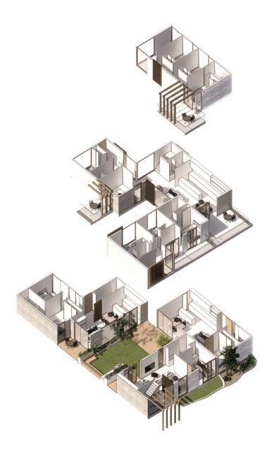
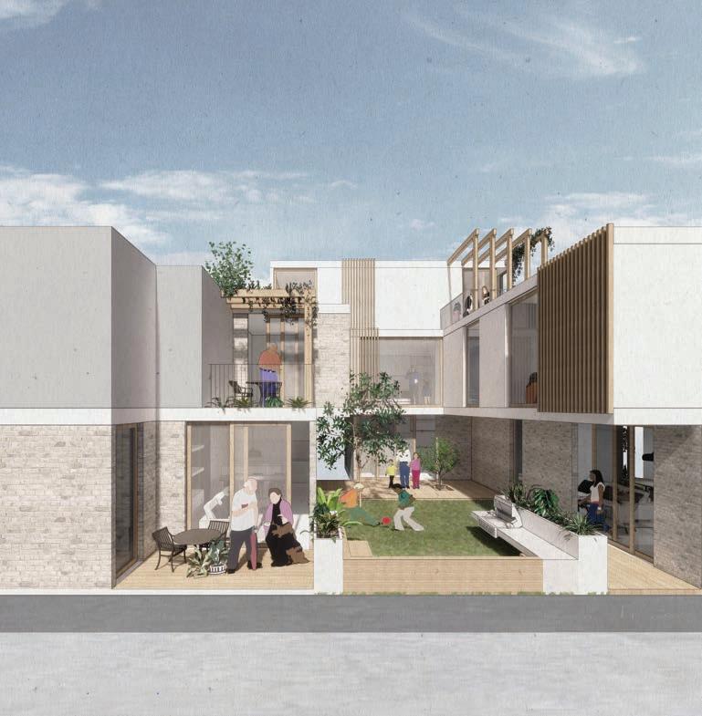
CLUSTER TWO: 375m
1 x 1 bed
1 x 2 bed
1 x 3/4 bed
1 x 5 bed
7.5 blocks
2 SM 2020 A005 CLUSTER BREAKDOWN COMMUNITY LIFE... CLUSTER LIFE
“Albert and Carmel choose a two-bedroom single level apartment which provides them with plenty of storage, and a spare room for grandchildren to play and sleep when they come to visit. This spare room can be converted in the future to cater for visitors or a livein carer, making it somewhere they can age comfortably, with no level changes and wider corridors appropriate for accessibility.”

Large living area can accommodate dinners with family and friends
Spare bedroom used as a playroom for when Albert and Carmels’ grandchildren come to visit
“Courtney and Jen start in their apartment as a couple but they are anticipating a family. While utilising the upstairs spare bedrooms as workspaces they later transition these spaces to child play spaces. The flexible ground floor space provides a location for a music teaching studio.”

Home office to become nursery as Courtney and Jen grow their family
Inspiration room for to inspire Courtney in her music song writing
“The Chu’s chose the larger apartment to cater for their expanding family. The conversion of a study space into a fourth bedroom allows each child to have their own space after sharing while younger. The playroom can then transform into a second living space, that is more private and perfect to settle in and watch a movie.”
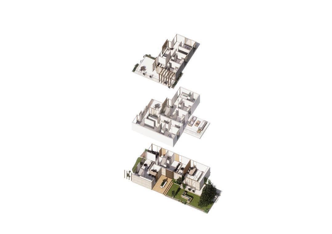
Home office for Amber and Phil who work from home at front of house to host meetings if necessary
Kids playroom

Mess can be closed off, close to kitchen for parents to keep an eye on kids
Music room with external access for Courtney to hold music lessons to students
Large family multipurpose dining table


Kids bedrooms and nursery close to parents when young
Play room becomes media room

2 SM 2020
A006 UNIT ADAPTIBILITY... AS SPECIFIED
Student Competition
Albert & Carmel Jones Relaxed Retirees...
Courtney & Jen Barnett Career to kids...
The Chu’s Flexiblefamily...
MOVE
FIRST FLOOR
FLOOR MOVE IN FIRST FLOOR MOVE IN SECOND FLOOR MOVE IN
GROUND FLOOR
IN
GROUND


2 SM 2020 Student Competition A007 CLUSTER BREAKDOWN COMMUNITY LIFE... CLUSTER LIFE CLUSTER ONE: 250m2 1 x 3/4 bed 1 x 5 bed 5 blocks
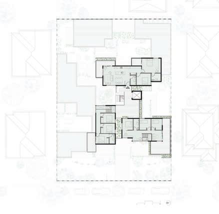
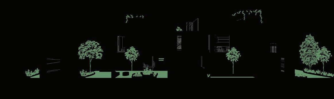
2 SM 2020 Student Competition A010 PLANS & SECTION AS SPECIFIED LEVEL TWO FLOOR PLAN LEVEL ONE FLOOR PLAN SECTION A A A A A
COMMHAUS seeks to be a catalyst for industry change creating a model that not only allows for the anticipated densification of Melbourne, but also maintains the current suburban qualities currently highly sought after in Melbourne’s middle suburbs.
The project is built upon clusters of households within a larger community where residents’ lives are enhanced by not only the social aspects of integrated living, but also through the benefits of selective shared spaces.
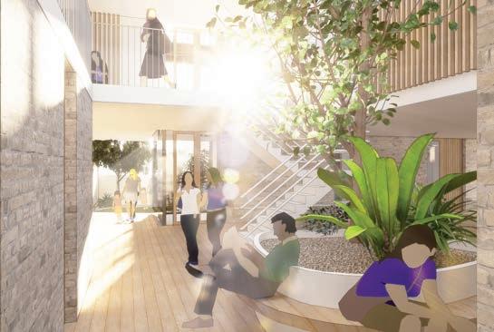
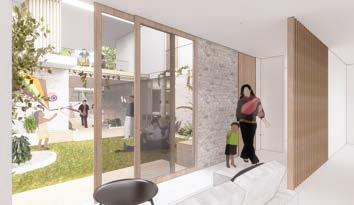
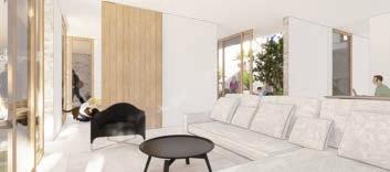
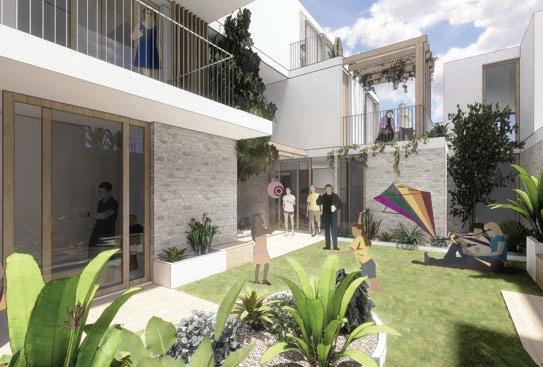
By achieving a balance between moments of privacy with aspects of communal living, the model drives down both living and environmental impact costs.

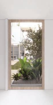
COMMHAUS is an adaptable housing cooperative model where a diverse set of housing typologies are provided through a participatory design process resulting in an architectural outcome that caters for many lifestyles and many lifestyle changes over time.
With a strong relationship between the internal and external, COMMHAUS provides high quality communal spaces that encourage interaction and relationships. With the broader community also considered through scale, form and materiality that link COMMHAUS to its neighbouring properties, helping people to connect to the design, again enforcing the importance of community.
2 SM 2020 Student Competition A018 RENDER PERSPECTIVE EXTERIOR RENDER COMMUNITY COURTYARD LIVING 2 SM 2020 Student Competition A016 RENDER PERSPECTIVE PRIVACY WINDOW INTERIOR RENDER OPEN LIVING WITH ACCESS TO COURTYARDS INTERIOR RENDER OPEN LIVING WITH ACCESS TO COURTYARDS SM 2020 Student Competition A015 RENDER PERSPECTIVE CENTRAL LIGHT COURT
Master of Architecture
Thesis, 2021
THE AIM OF MY DESIGN AND THESIS HAS BEEN CREATING SPACES THAT FOSTER A COMMUNITY WITHIN BALLARAT THAT RESPECT THE HISTORY OF THE TOWN AND ITS PEOPLE, WHILE PROVIDING FOR THE CURRENT AND FUTURE BALLARAT COMMUNITY. AIM TO DESIGN A DEVELOPMENT THAT PROVIDES A NEW OFFERING WITHIN BALLARAT WHILE ALSO ENCOURAGING AND SUPPORTING A DEEPER CONNECTION TO THE RICH HISTORY, COMMUNITY AND LANDSCAPE THAT IS ALREADY IN PLACE. USING A TECHNIQUE OF LOOKING BACK TO HISTORICAL DESIGN ELEMENTS AND APPLYING THEM IN A CONTEMPORARY FASHION, MY DESIGN PROJECT AIMS TO CREATE AN ARCHITECTURE THAT INTEGRATES WITH THE OLD IN A RESPECTFUL WAY WHILE STILL MAKING ITS OWN IMPACT ON THE CITY.
PROCESS OF SYNTHESIS
‘the combination of components or elements to form a connected whole’
THE CENTRAL COURTYARD IS APARTMENTS AND COMMUNAL SPACES TO PROVIDE SAFETY AND RESPECTS THE OLD WHILE MAKING


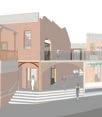


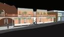
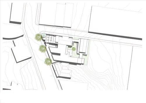
THE ARCH
USED IN EXISTING HERITAGE BUILDINGS TO REPRESENT THE ENTRANCE, THE ARCH HAS BEEN USED IN THE NEW DESIGN TO DEFINE ENTRANCES INTO PUBLIC AND SHARED AREAS. A WAY OF WELCOMING PEOPLE AND ENCOURAGING INTERACTION THROUGHOUT
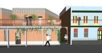
THROUGHOUT THE DESIGN TO ENCOURAGE SPONTANEOUS EACH OTHER AS THEY ACCESS THEIR PROVIDES RESIDENTS VIEWS TO AND A CONNECTION WITH NATURE IN
THE BRICK
THE EXISTING AND PROPOSED BUILDING FORMS ARE ASSIGNED LETTERS. THE DESIGN ELEMENTS VIEWED AS SIGNIFICANT FROM THE HERITAGE BUILDINGS ARE LISTED, AS WELL AS ELEMENTS THAT ARE DESIRED IN THE PROPOSED DESIGN.
THESE ELEMENTS ARE THEN COMBINED TO CREATE AN ARCHITECTURE THAT IS A SYNTHESIS OF THE EXISTING AND NEW.
A MATERIAL KNOWN FOR ITS DURABILITY, USED IN MOST OF BALLARATS HISTORIC BUILDINGS. A CONTEMPORARY APPROACH OF BRICK TILES CREATES A RELATIONSHIP WHILE TAKING ADVANTAGE OF MODERN CONSTRUCTION TECHNIQUES.
THE VERANDA A REPEATED ELEMENT ALONG CAMP STREET AND BROADER BALLARAT. ACTIVATES THE STREET, CREATES A RELATIONSHIP BETWEEN GROUND AND ABOVE. FORMS A THRESHOLD ALLOWING PEOPLE TO INTERACT WITH THE STREET WHILE MAINTAINING A SENSE OF SEPARATION.
THE ARCH USED IN EXISTING HERITAGE BUILDINGS TO REPRESENT THE ENTRANCE, THE ARCH HAS BEEN USED IN THE NEW DESIGN TO DEFINE ENTRANCES INTO PUBLIC AND SHARED AREAS. A WAY OF WELCOMING PEOPLE AND ENCOURAGING INTERACTION THROUGHOUT
THE BRICK A MATERIAL KNOWN FOR ITS DURABILITY, USED IN MOST OF BALLARATS HISTORIC BUILDINGS. A CONTEMPORARY APPROACH OF BRICK TILES CREATES A RELATIONSHIP WHILE TAKING ADVANTAGE OF MODERN CONSTRUCTION TECHNIQUES.
THE TERRACE DESIGNED TO BE APPRECIATED ON THEIR OWN AS MUCH AS PART OF A ROW. THIS IDEA HAS BEEN CONTINUED IN THE NEW BUILDINGS TO CREATE A RHYTHM ON THE STREET FRONT WHILE ALSO BREAKING UP THE FORM USING THE TERRACE STYLE NARROW STREET FACE.
THE VERANDA A REPEATED ELEMENT ALONG CAMP STREET AND BROADER BALLARAT. ACTIVATES THE STREET, CREATES A RELATIONSHIP BETWEEN GROUND AND ABOVE. FORMS A THRESHOLD ALLOWING PEOPLE TO INTERACT WITH THE STREET WHILE MAINTAINING A SENSE OF SEPARATION.
THE STAIR
THE STAIR IS USED TO MARK A CHANGE BETWEEN PUBLIC AND PRIVATE SPACES, DEFINING AN ENTRANCE FROM THE STREET. USED TO DEFINE THE MAIN CAMP STREET ENTRANCE, THE STAIRS CREATE A CONNECTION WITH THE EXISTING YMCA STAIRS AS WELL AS MARKING CHANGES BETWEEN PUBLIC AND PRIVATE.
SYNTHESIS
LETTER ASSIGN LETTER A Aa Ab B Ba Ba B NEW DESIGN SOLUTION STEP1 STEP2 STEP3 A
WESTERN ELEVATION
NORTHERN ELEVATION
The sections show how open the design is, even though it is a large complex, the form has been broken up in a way that means there are no large blank walls or masses. The various entrances from each side means people are moving through the design, rather than entering and turning back around, making it more inviting for the residents and the public. The sections also show how the design nestles into the slope, taking advantage of the unique site, rather than just flattening the area.

HERITAGE TERRACE SECTION SECTION 1 SECTION 2
INSTALLING ARCHES
I N S T A L L I N G A R C H E S
Step 5: Concealed lintel system installed to create arched opening in existing double brick wall
As well as creating relationship between the old and new, I wanted my design to encourage relationships between residents and foster a sense of community. Therefore I wanted to create various spaces across the project that encourage interaction between residents and the public, this also connects back to the YMCA’s original use as a place for young people to come together and form connections. The Camp Street façade was very important in my design. I wanted to maintain the existing rhythm of the street and create a façade that welcomes people in, activating the street at ground level, as well as the level above. This relationship between various levels has continued throughout the design with raised walkways, bridges and verandas wrapping around the complex.


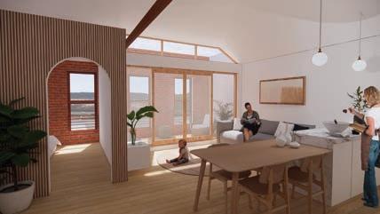
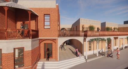
1:50 FRONT FACADE SECTION
When working with heritage buildings, it is important to ensure any new design is respectful of the existing structures. The design outcome should vary with each project as each heritage site is unique, therefore there is not a single aesthetic or style that can be applied to all. My thesis involved a lot of research into the history of the site and its surrounding area which was extremely influential in the design I produced. I believe a high level of research into heritage sites is crucial when they are involved in architectural projects, therefore the design approach I implemented is a way to increase this research. By drawing out the important elements of the existing structures, designers are encouraged to look further into the site and can use this knowledge to design a more integrated and respectful architecture. By also listing the defining features that are desired in the design, architects can ensure their project is respectful of the old while also providing for the current and future generations of Ballarat.
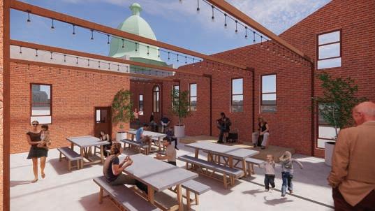
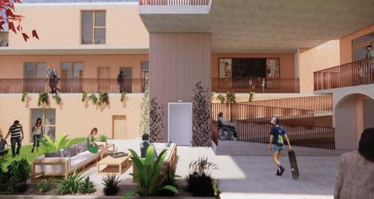
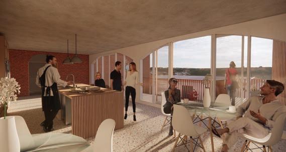


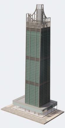
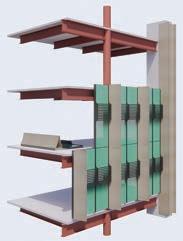


Project Drawing Revisions Status Disclaimers, Comments Notes Final Submission Facade Concept Diagrams -20.06.20For Construction MA FACADE DETAIL NTS Shade Louvres Optimised to the solar orientation of each facade 1050mm SCREENING 4000mm FLOOR TO FLOOR ONYX SOLAR INTEGRATED PV SPANDREL GLASS VISION PANEL VERTICAL SHADING ELEMENTS AND COLUMN COVER CAPRAL EXTRUDED HORIZONTAL SHADE LOUVRES 1000mm CLADDING TO MEGA COLUMN DIGITAL MODEL NTS DIGITAL MODEL NTS Madeleine Archer 836 470 DRAWINGS NOT TO SCALE

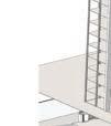
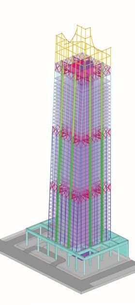
DRAWINGS NOT TO SCALE L35 (Typical High Rise) RL 151.200 L36 RL 154.800 2 OUTSIDE EB2 EB2 C6 3600 L19 RL 84.000 2 1 6000 SL1 B2 EB1 C2 BEHIND SCALE 1 50 A2.2 TYPICAL SECTION SCALE VERTICAL STRUCTURE DIAGRAM 3 SCALE TYPICAL STRUCTURAL CONNECTIONS L35 (Typical High Rise) RL 151.200 L36 RL 154.800 2 OUTSIDE EB2 EB2 C6 3600 L19 RL 84.000 2 1 6000 SCALE 1 50 A2.2 TYPICAL SECTION SCALE VERTICAL STRUCTURE DIAGRAM 3 SCALE TYPICAL STRUCTURAL CONNECTIONS L35 (Typical High Rise) RL 151.200 L36 RL 154.800 2 OUTSIDE SL1 SL1 B4 B4 EB2 EB2 C6 C3 BEHIND 3600 2946 6000 L19 RL 84.000 2 1 6000 6000 SCALE 1 50 A2.2 TYPICAL HIGH RISE STRUCTURE SECTION 1 SCALE VERTICAL STRUCTURE DIAGRAM 3 SCALE TYPICAL STRUCTURAL CONNECTIONS DIAGRAM -1 4 L35 (Typical High Rise) RL 151.200 L36 RL 154.800 OUTSIDE 3600 L19 RL 84.000 1 OUTSIDE 6000 4000 SL1 B2 EB1 C5 C2 BEHIND A2.2 SCALE VERTICAL STRUCTURE DIAGRAM 3 SCALE TYPICAL CONNECTIONS 3D GRAPHIC NOT TO SCALE OUTRIGGER BEAM BELT TRUSS C4 500mm CHS C1 1800 x 900mm MEGA PODIUM TRANSFER BEAM PODIUM MEGA COLUMN SL1 200mm CONDECK SLAB OUTRIGGER BEAM BELT TRUSS C5 400mm CHS C2 1600 x 800mm MEGA SL1 200mm CONDECK SLAB OUTRIGGER BEAM BELT TRUSS C6 350mm CHS C3 1200 x 600mm MEGA SL1 200mm CONDECK SLAB CORE BEHIND C6 350mm CHS B5 350mm CHS RETAINING WALL SL1 200mm CONDECK SLAB EB1 EB2 EDGE BEAM C1 C2 C3 MEGA COMPOSITE COLUMN C4 C5 C6 CHS B2 B4 SECONDARY BEAM