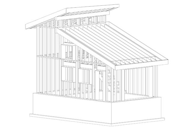
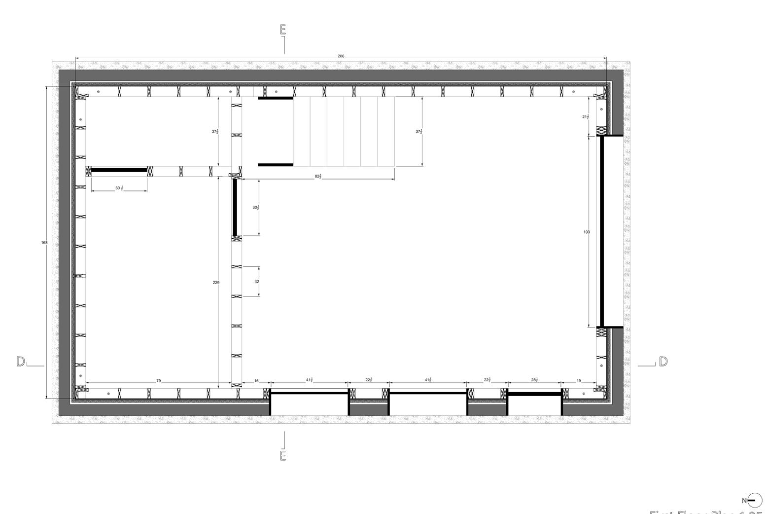
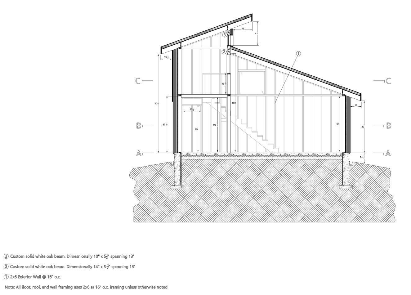
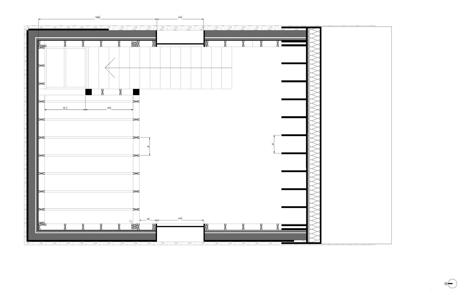
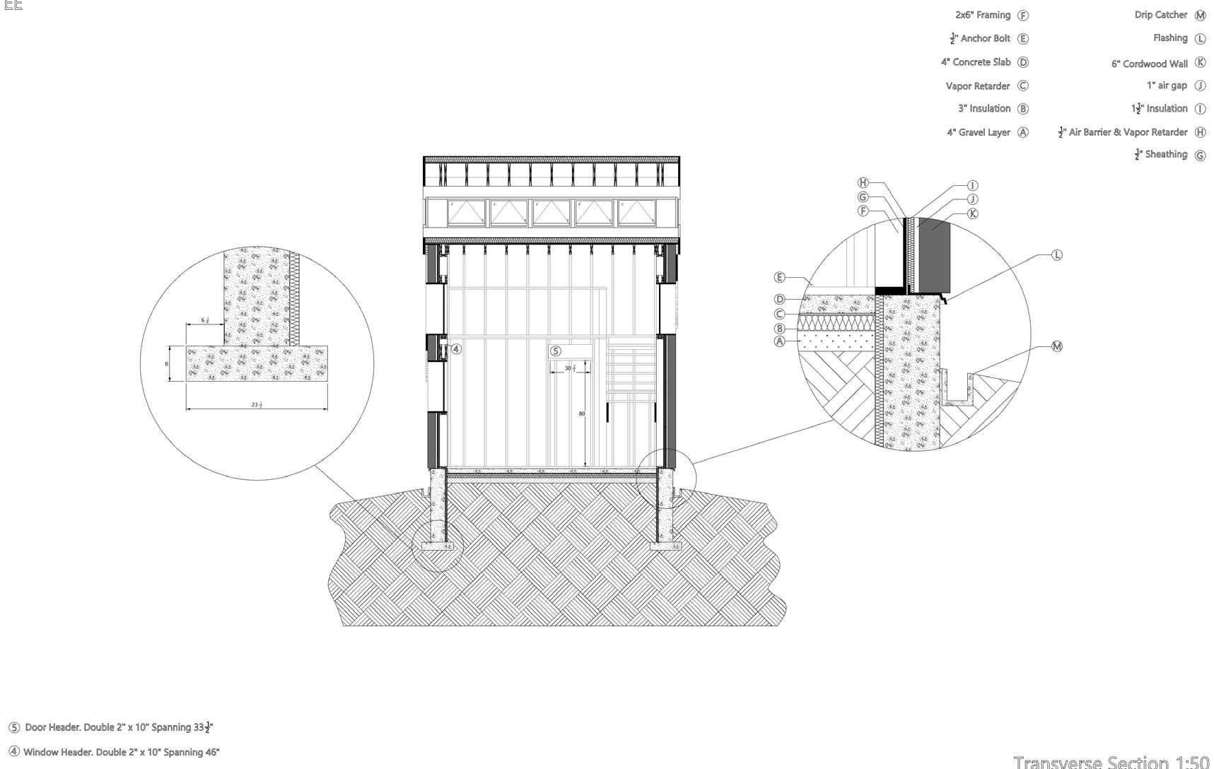
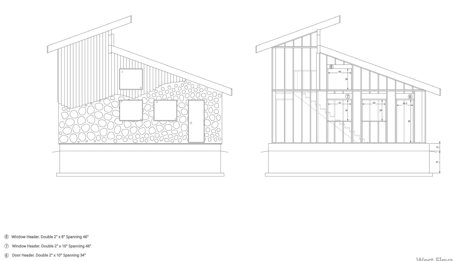
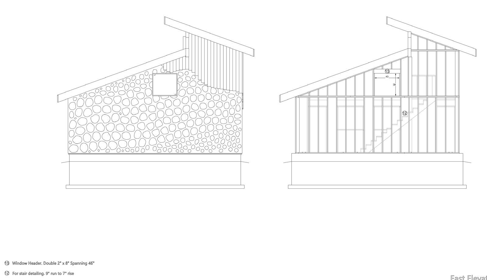
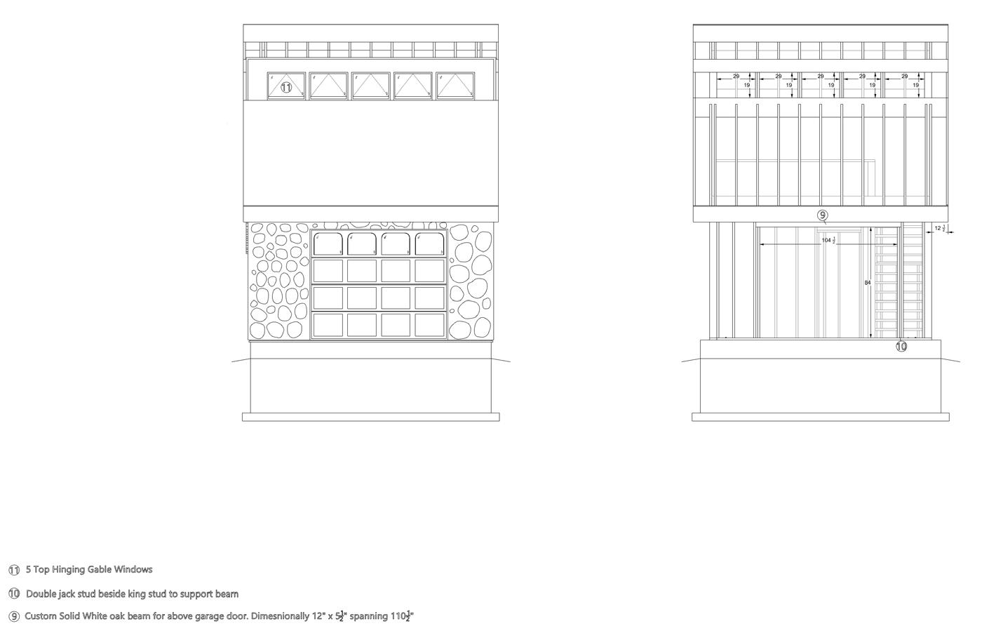
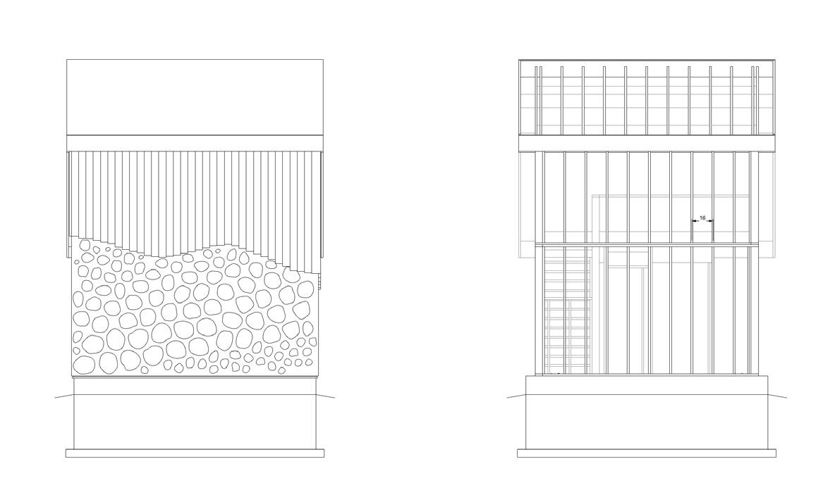
The Hobby House is an academic project, completed for a fourth-year wood frame technology course. The course was completed in a group of two; all the represented drawings and renders are my original contribution to the project.
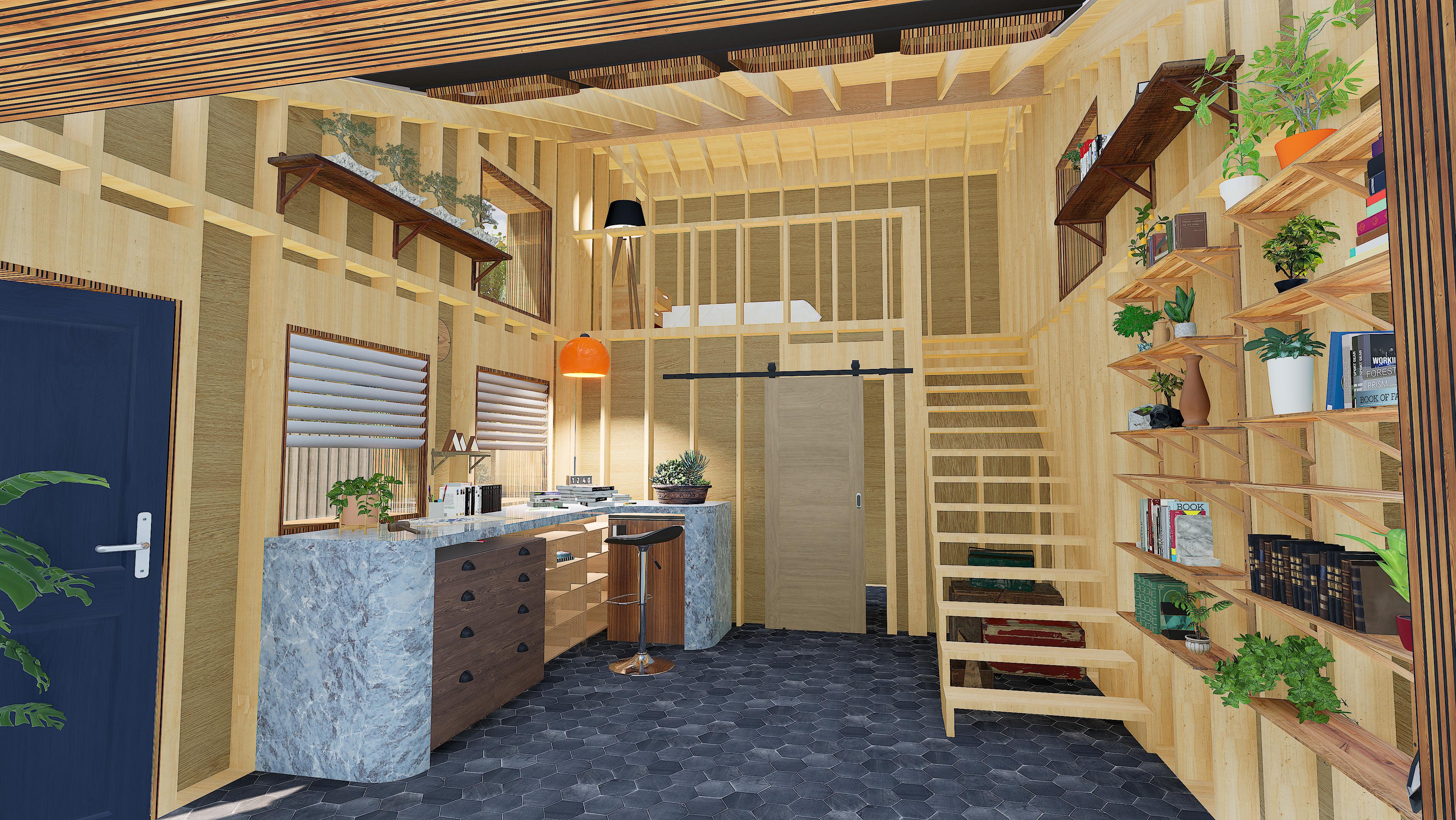
The proposed idea was a small garden suite with 135 square meters of floor space. The structure is built in accordance with Ontario’s Building Code and could be realized on a Toronto lot following the City of Toronto’s Garden Suite Guidelines.
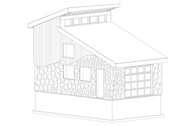
The idea of the garden suite aims to increase the livable area in the downtown Toronto area, where property and housing come at a premium.
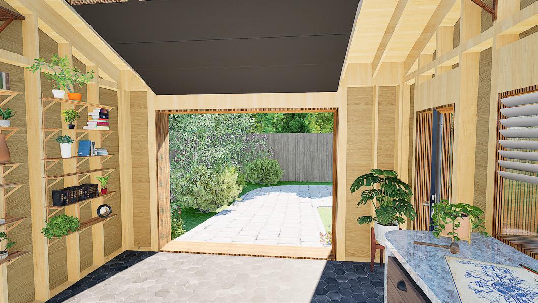
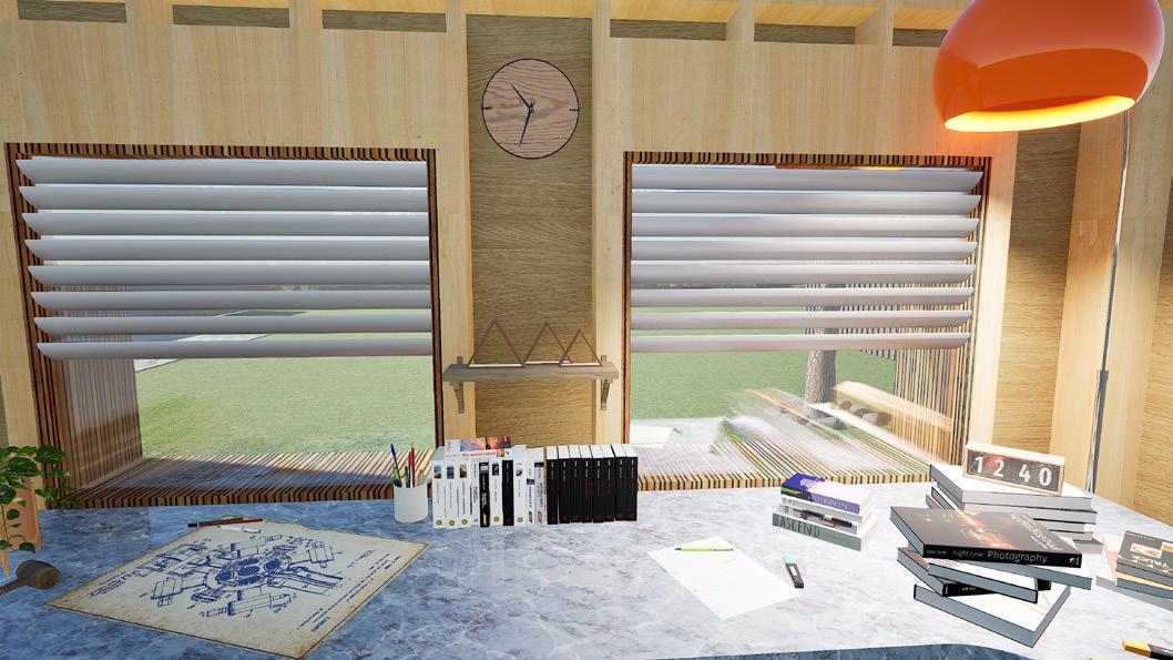
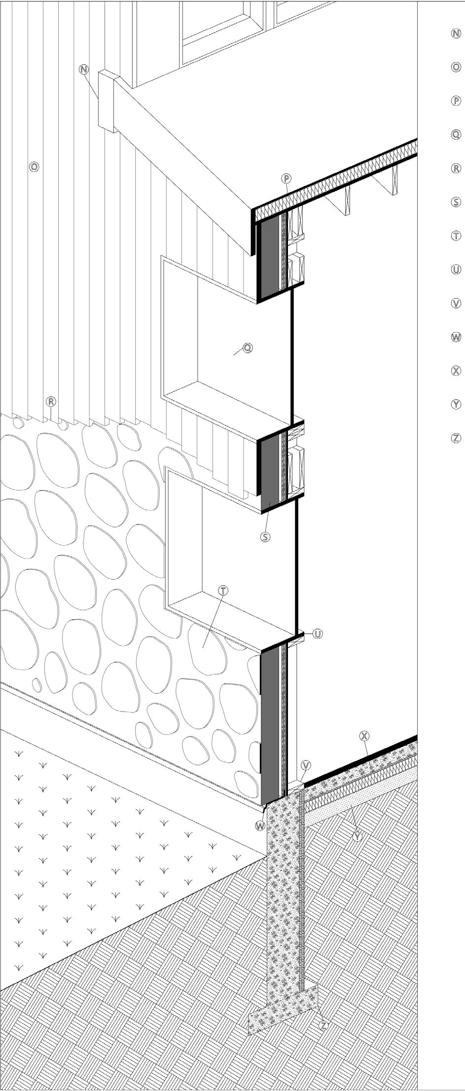
The suite is designed to act as a self-sufficient living space, with an open floor plan to support various hobbies and large-scale projects. The building also maintains a central focus on sustainability, following Passive House standards.
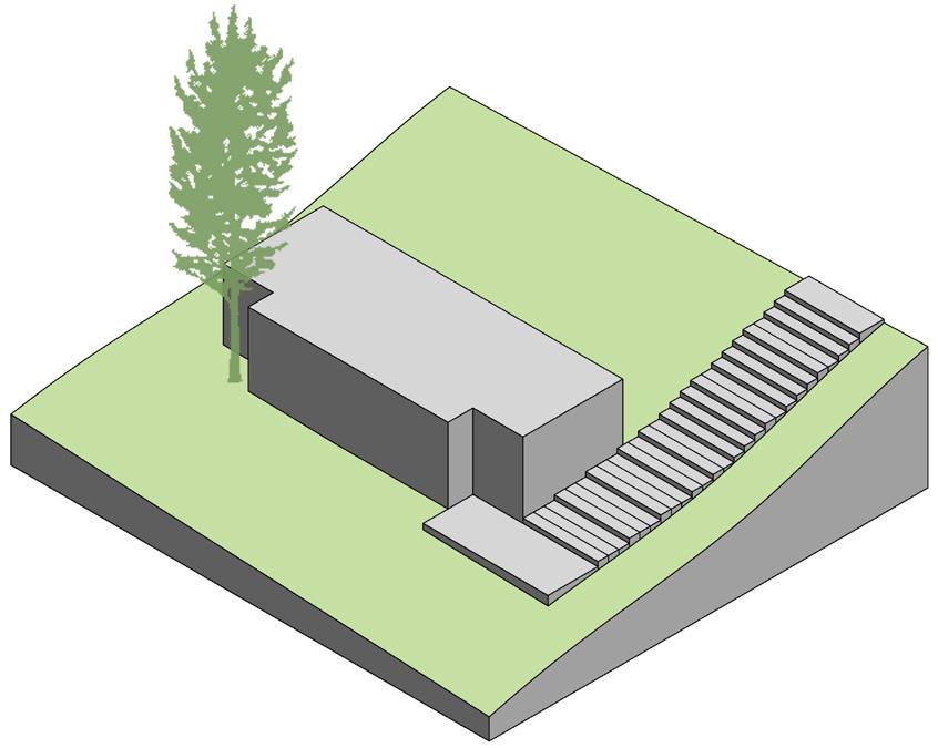
TThe Hill Houses are an academic project, completed for a third-year technology specialist studio course. The course was completed in a group of three; all the represented drawings, photos, and renders are my original contribution to the project. The model was completed with one other groupmate.
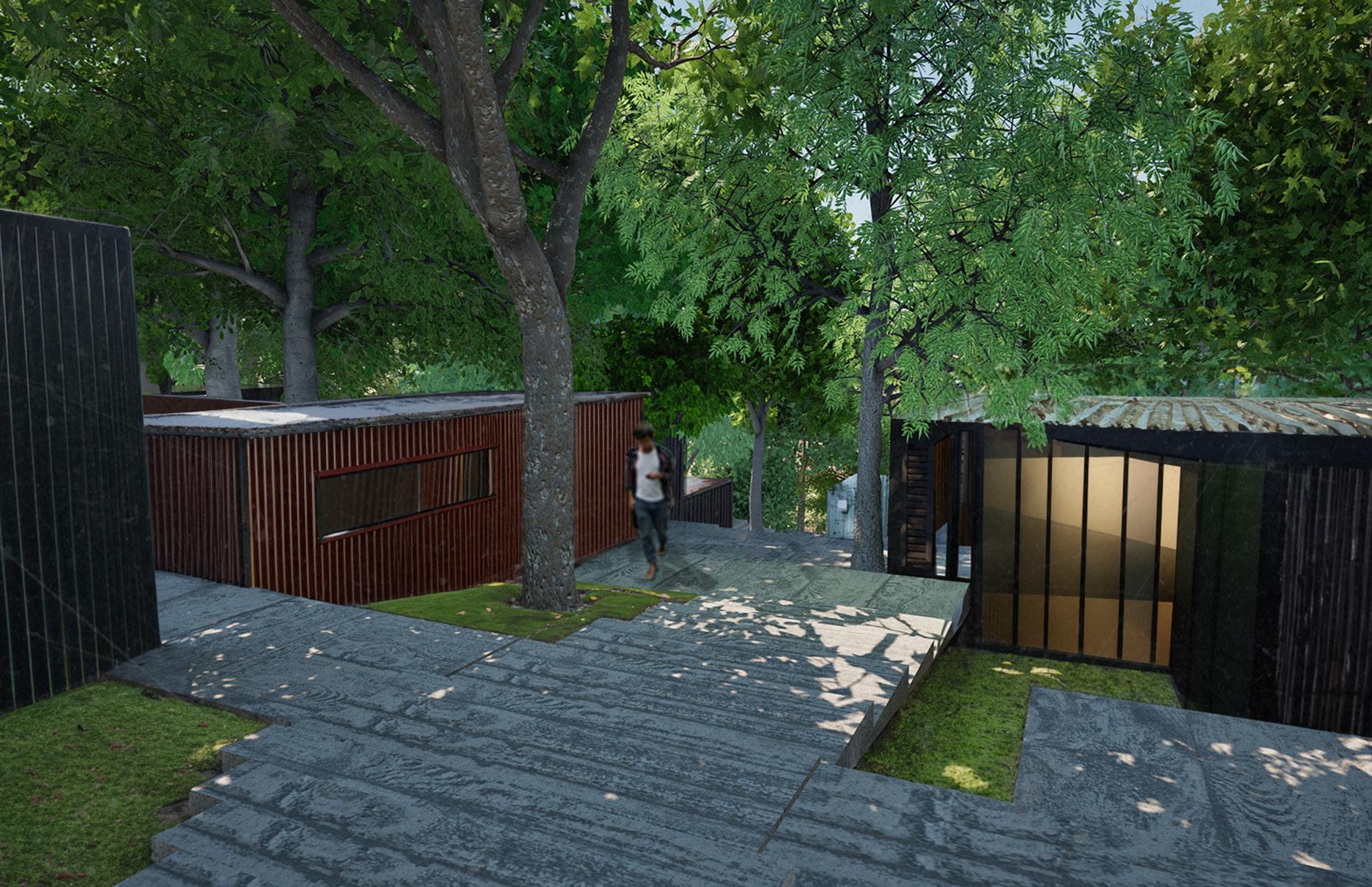
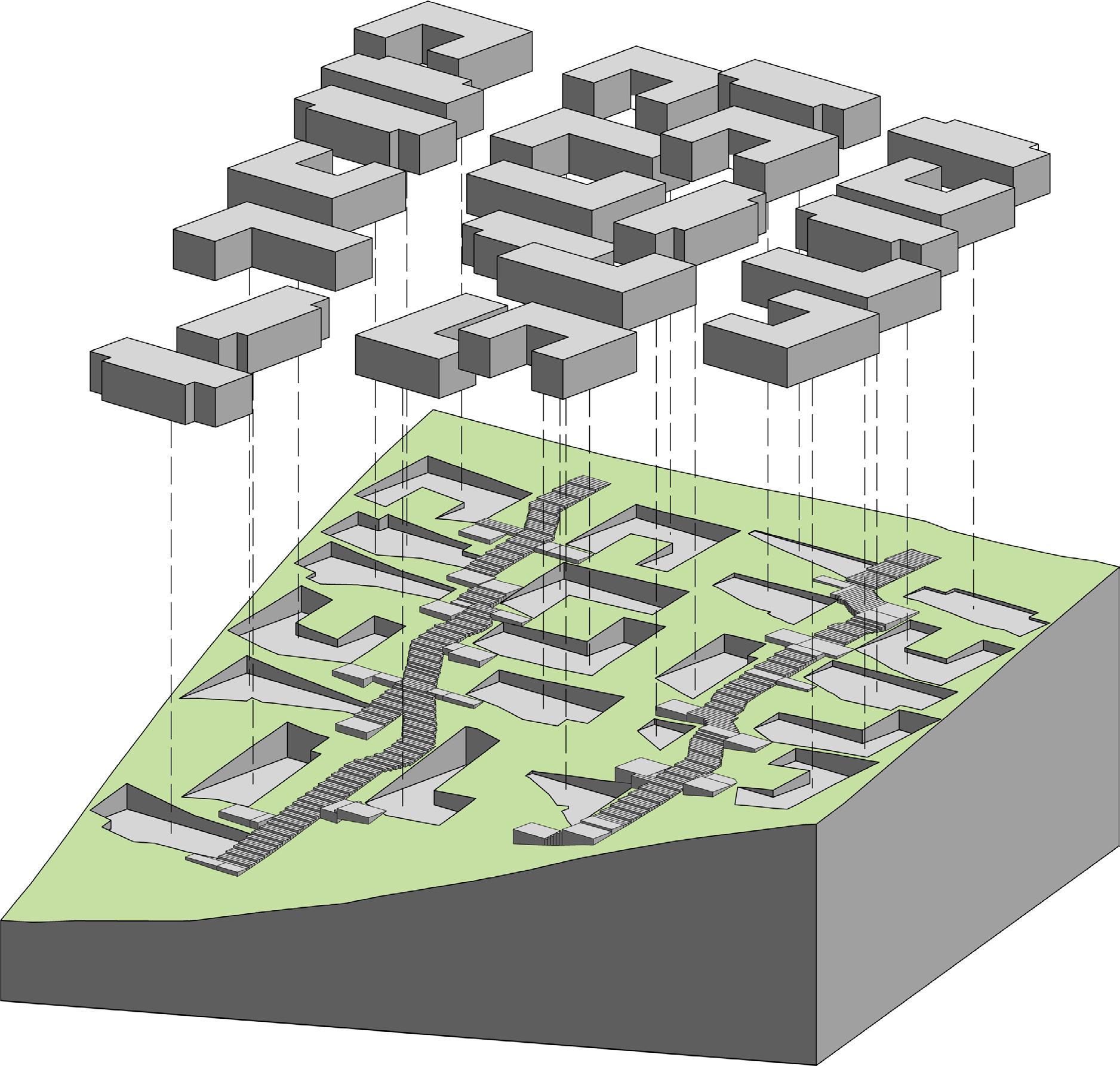
The project examined a gently sloping hill and arrayed AI-interpreted housing onto a grid optimized for the site topography. The design of the housing considered the density and lack of affordable housing in downtown Toronto. These small modular homes provide a higher density than single-detached or duplex homes, while still offering private space and a connection to nature.
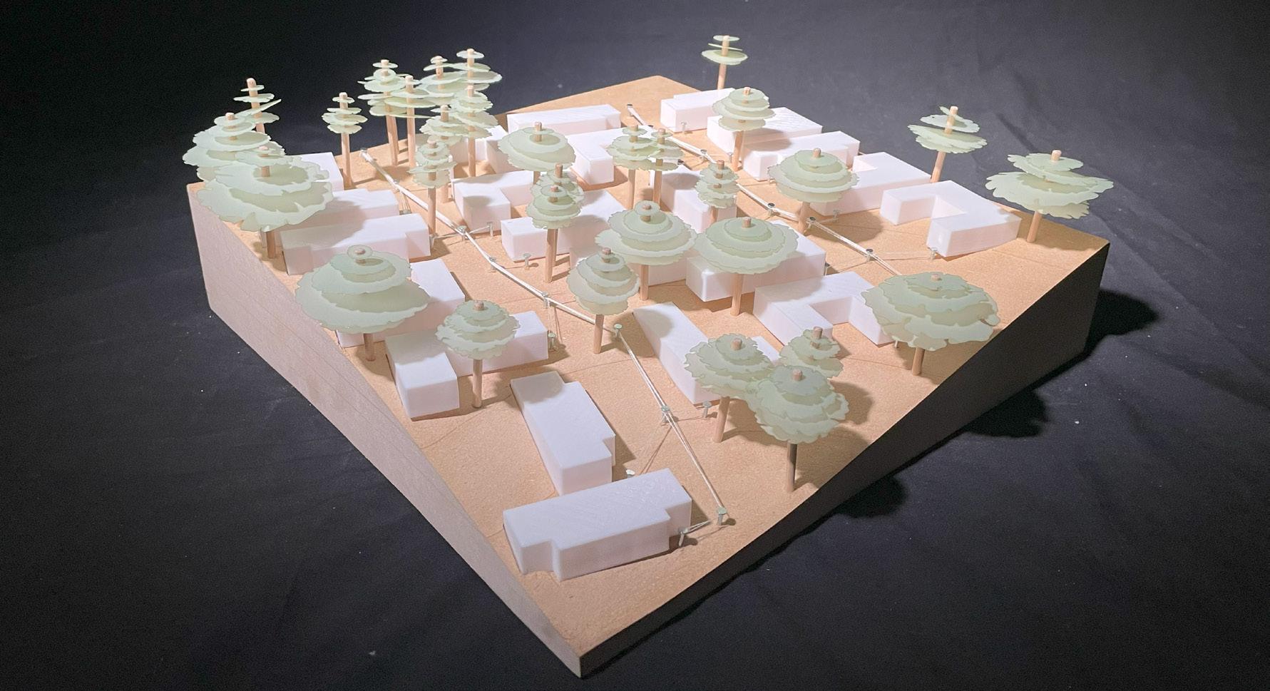
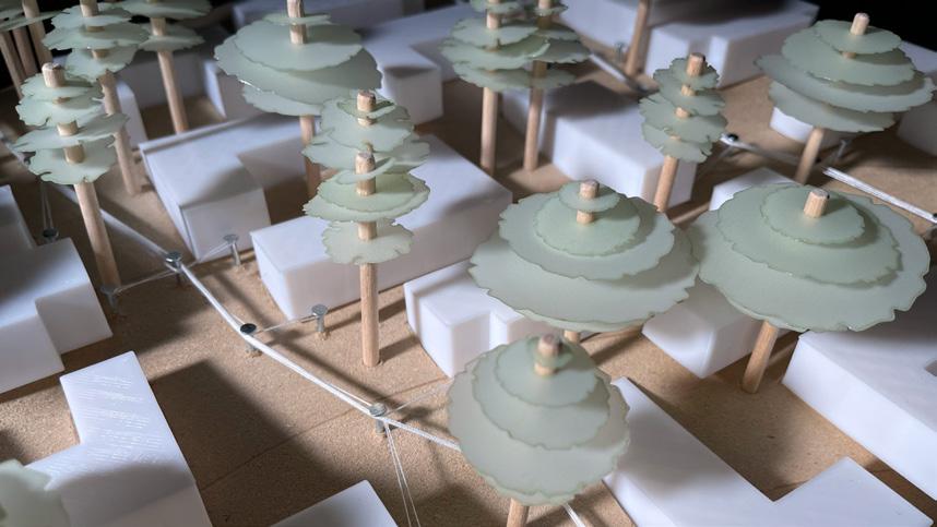
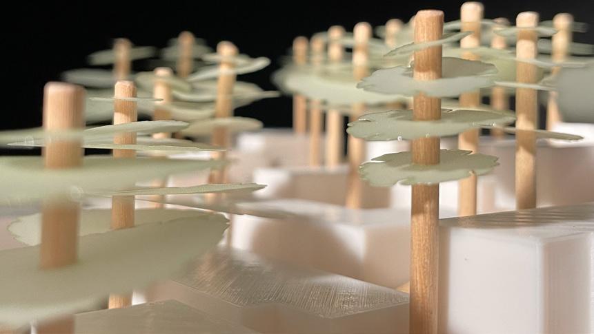
The model was created with one other groupmate, Sophia de Uria. We used a CNC to mill the topography out of a stock composed of half-inch MDF sheets. The houses were 3D printed. The leaf sheets for the trees were cut using a laser cutter, then assembled and added to the model. The string mapping the movement paths throughout the site was added by hand. The tacks act as nodes through which the white thread runs to connect all the houses. This is the same path the stairs follow.
AI Integration:
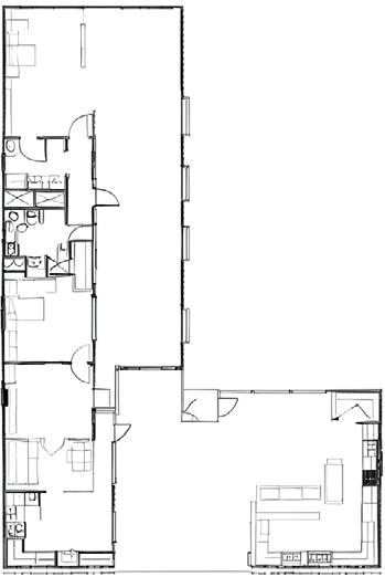
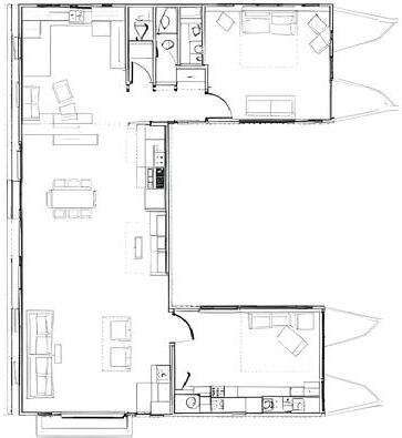
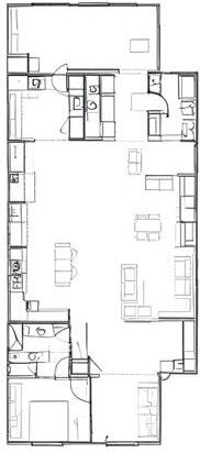
The design of the houses was informed through the use of AI. A model was trained on single-floor homes built from multiple shipping containers. Based on the AI output, the most predominant floor arrangements were found to be L, U, and I (as seen to the right). Interior plans were then generated for each of these volumes using the same AI model. The generated plans were interpreted and remapped by hand to create the final floorplans for each volume.
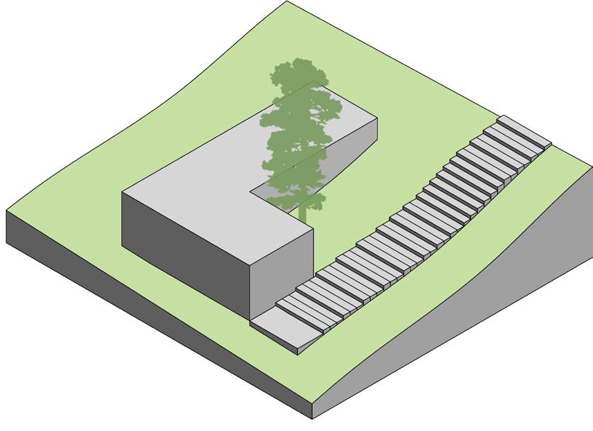
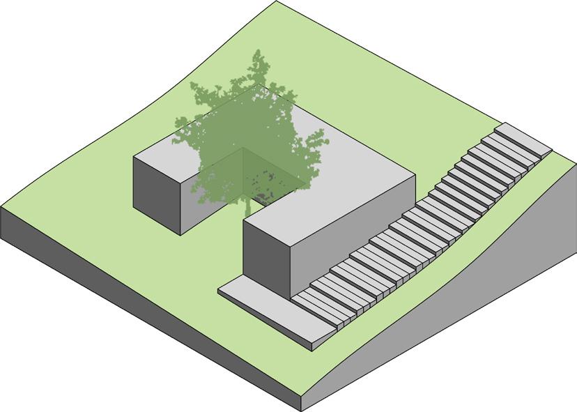
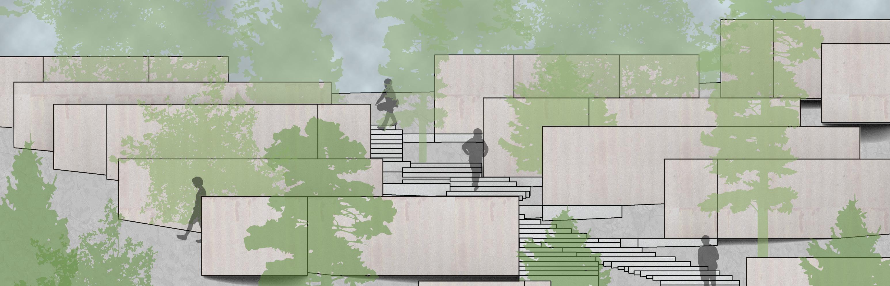
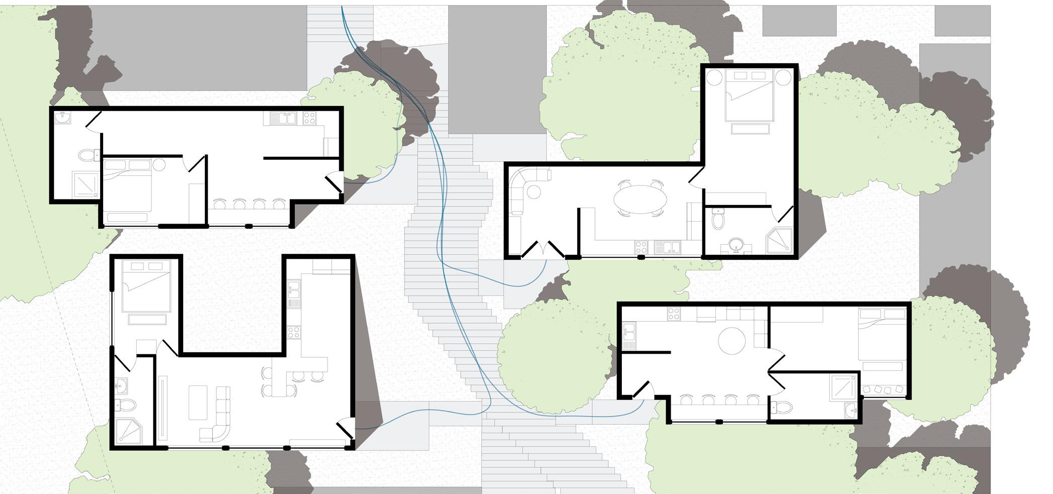
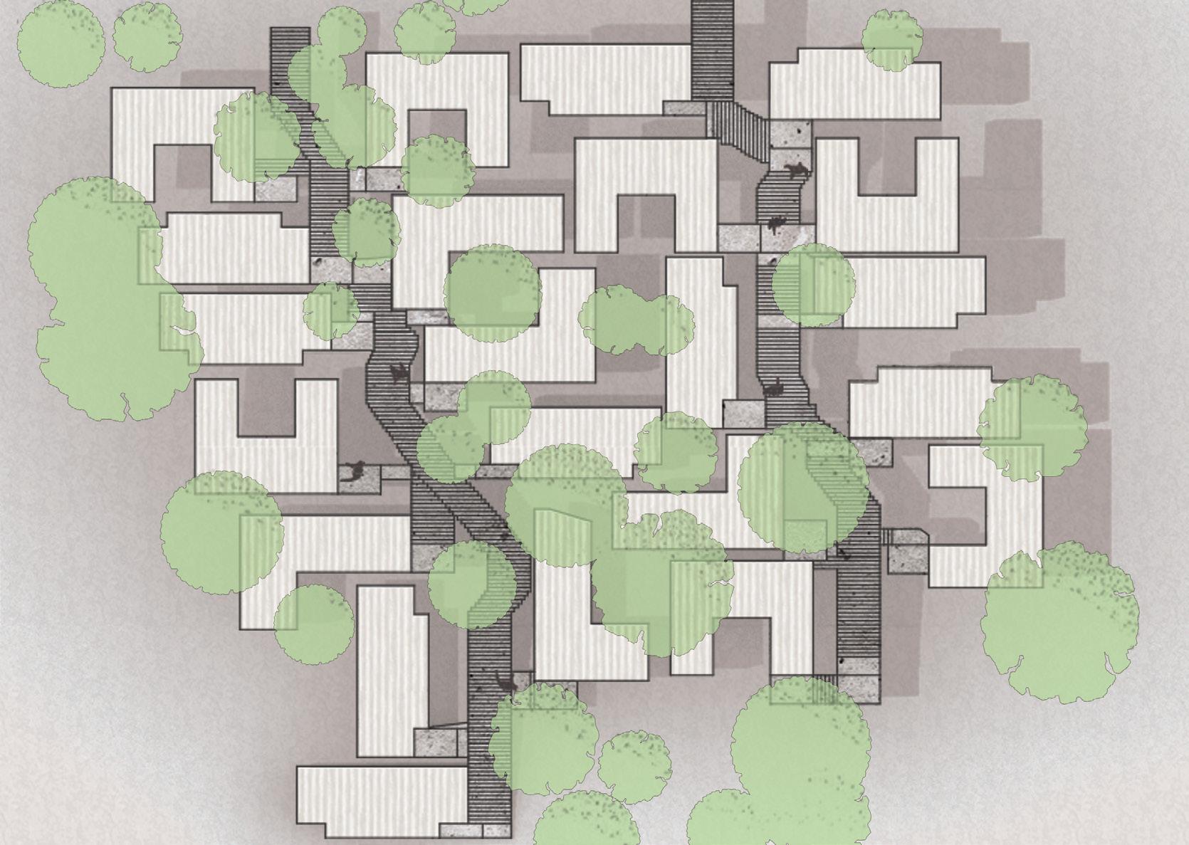
The arrangement of the optimized shipping container homes was arrayed with the primary intent of retaining the maximum number of existing trees. The secondary intent was to create courtyard areas in the remaining spaces that exist between the homes. Both intents aim to reinforce a connection between the residents and the surrounding nature.
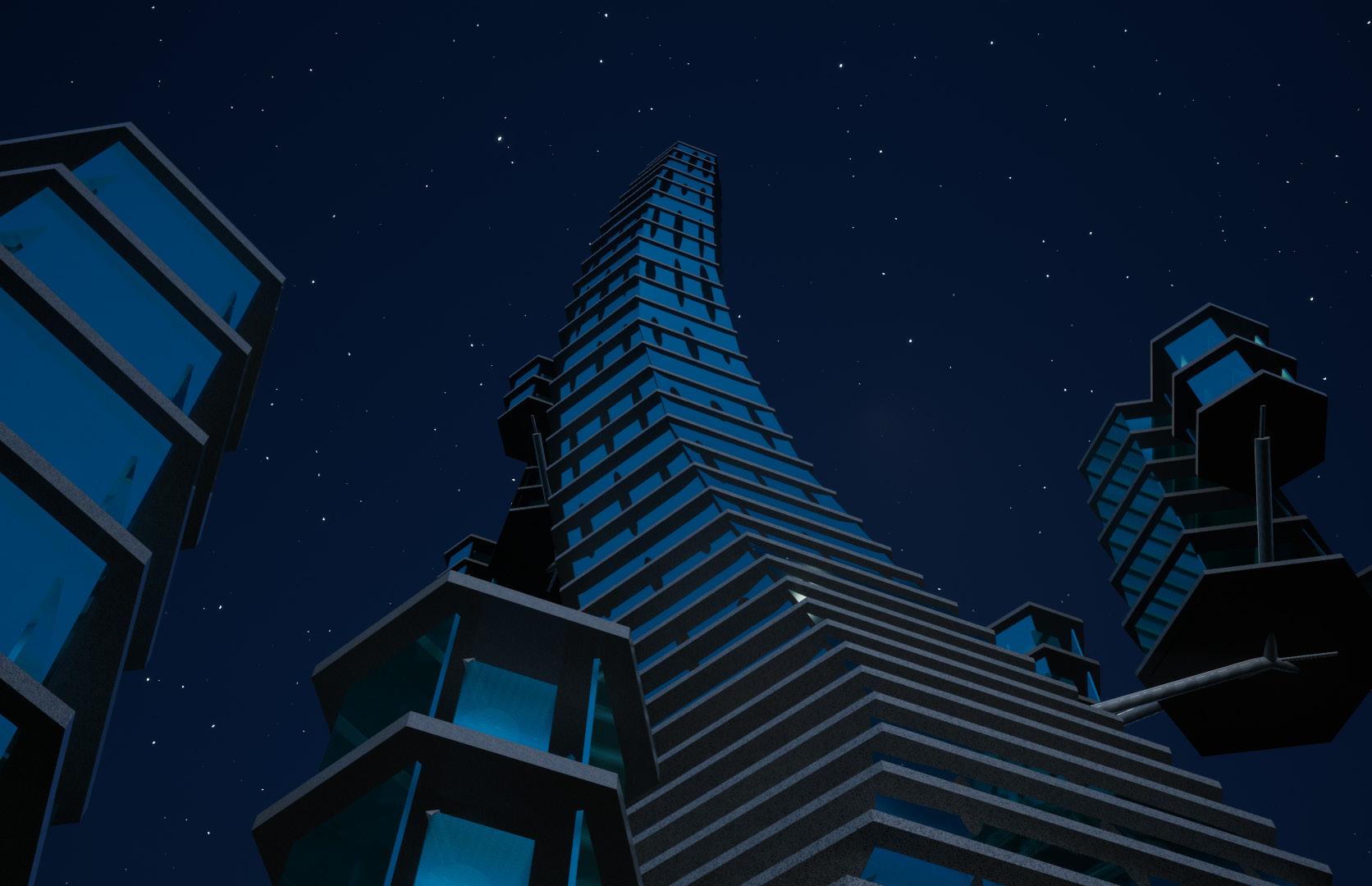
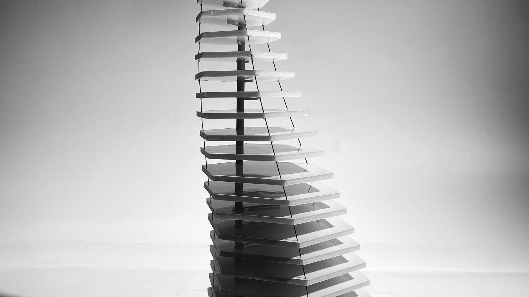
The Tower Triptych series is an academic project, completed individually for a second-year technology-focused studio course.
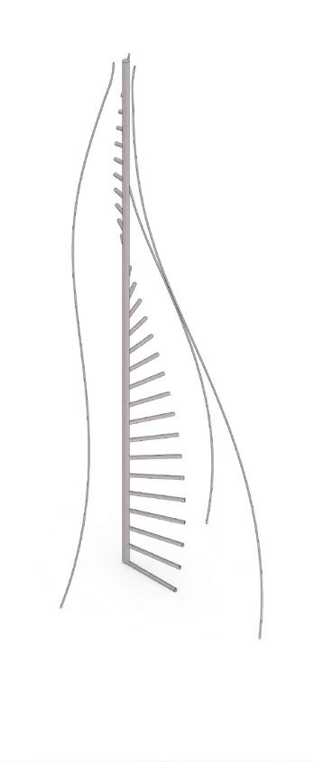
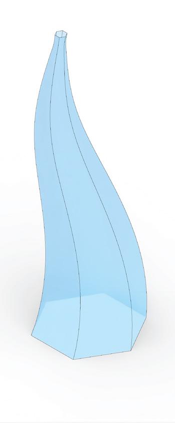
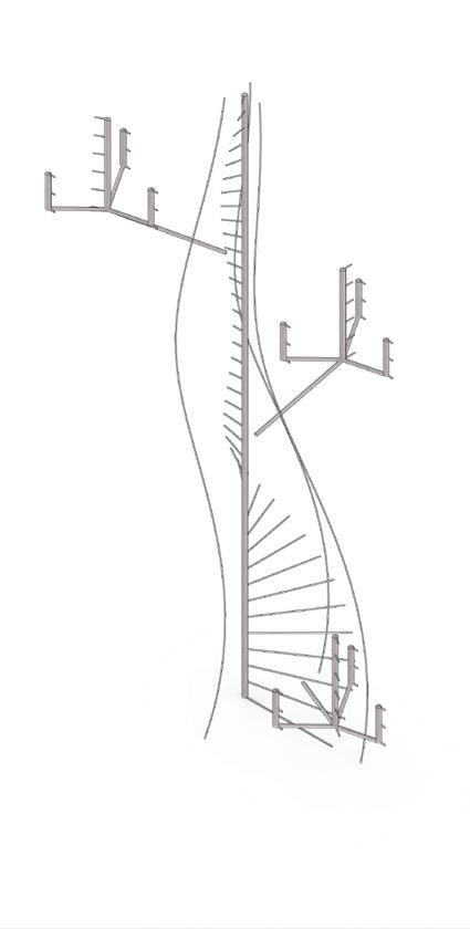
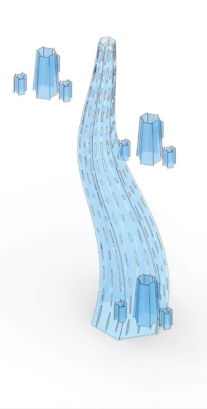
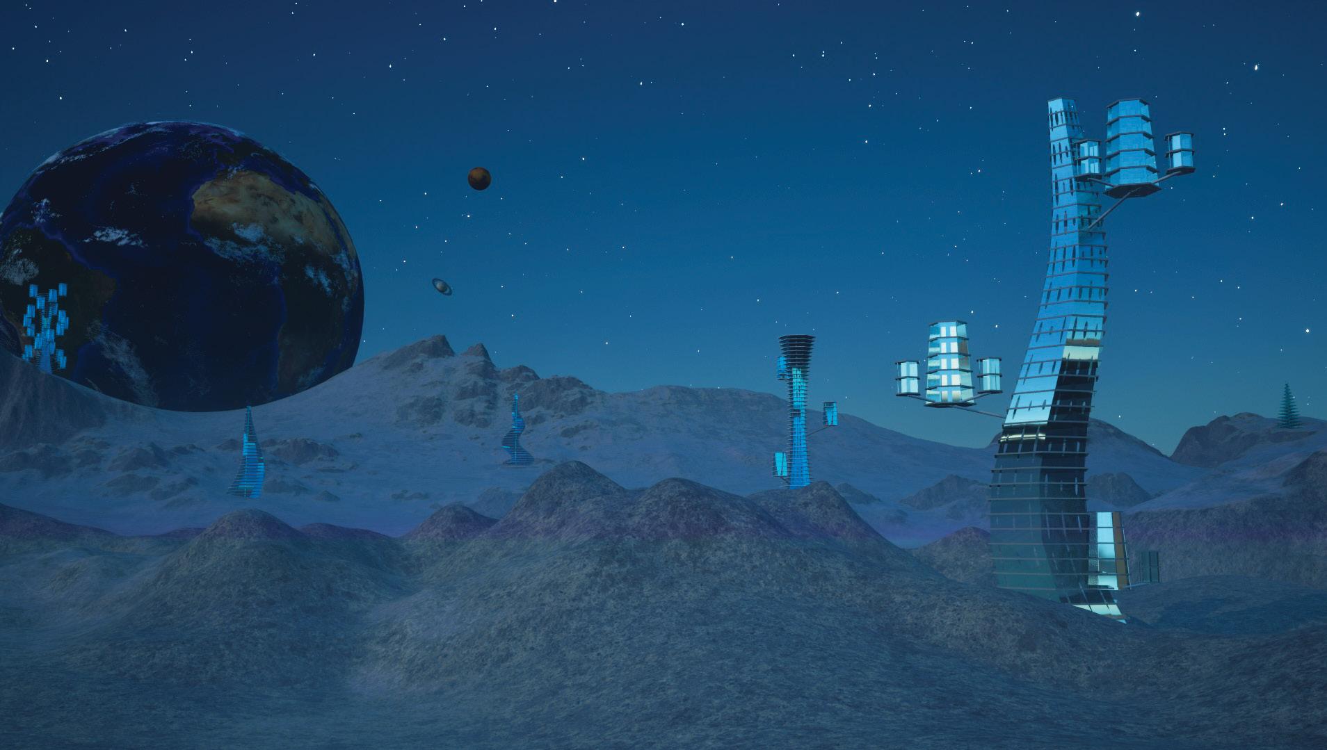
The set of towers is a collection of theoretical structures designed for inhabiting the moon, drawing inspiration from Earth’s plants incapable of survival in the moon’s climate. Tower 1 takes on a winding shape, reminiscent of a sapling that has just sprouted from the ground and winds upward toward daylight.
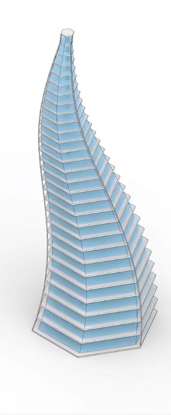
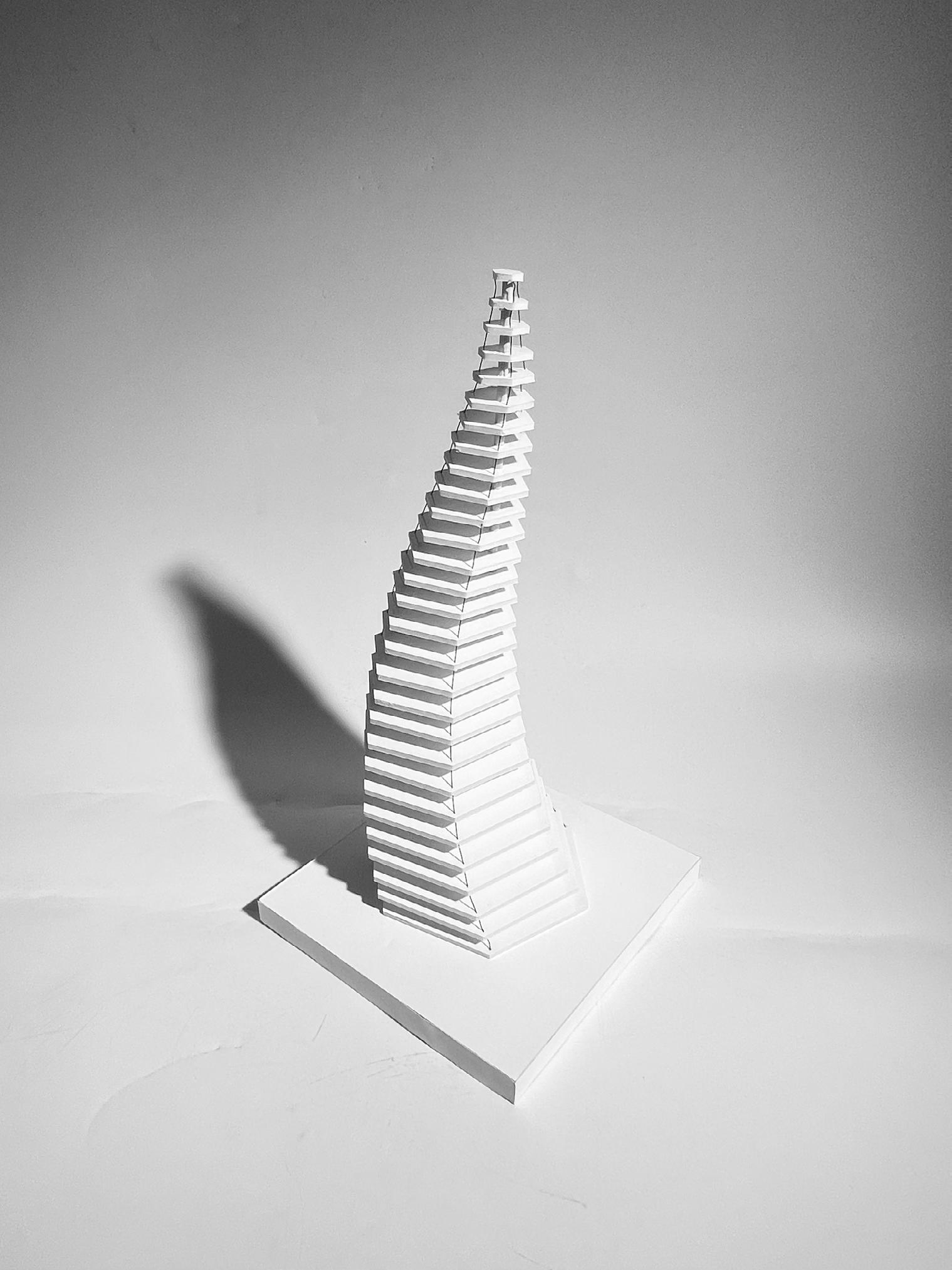
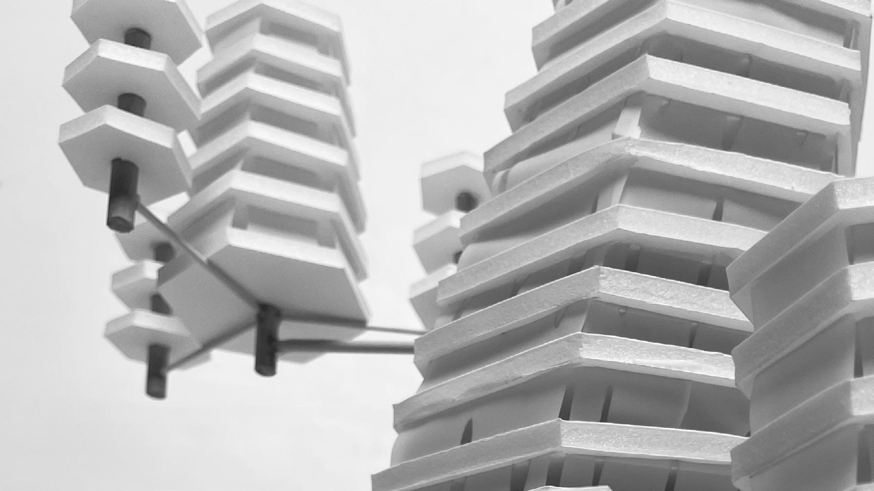
Tower 2 continues to push the boundaries of what would be practical to design on Earth, with miniature branching towers extruding from the main core. The inset building facade features elliptical windows that mimic the chloroplast cell structure within leaves, while the small tower arms directly mirror tree branches extending from the trunk.
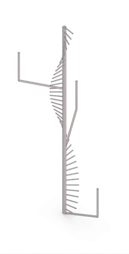
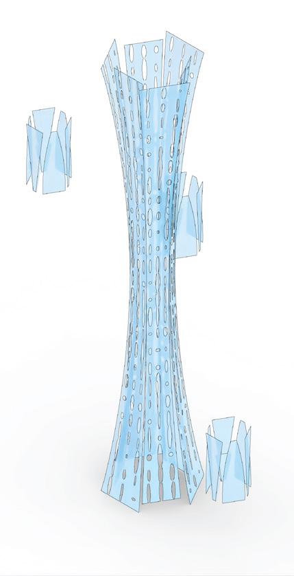
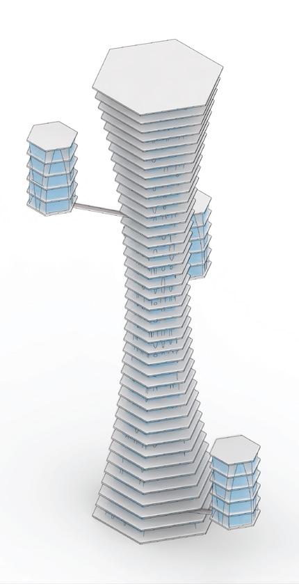
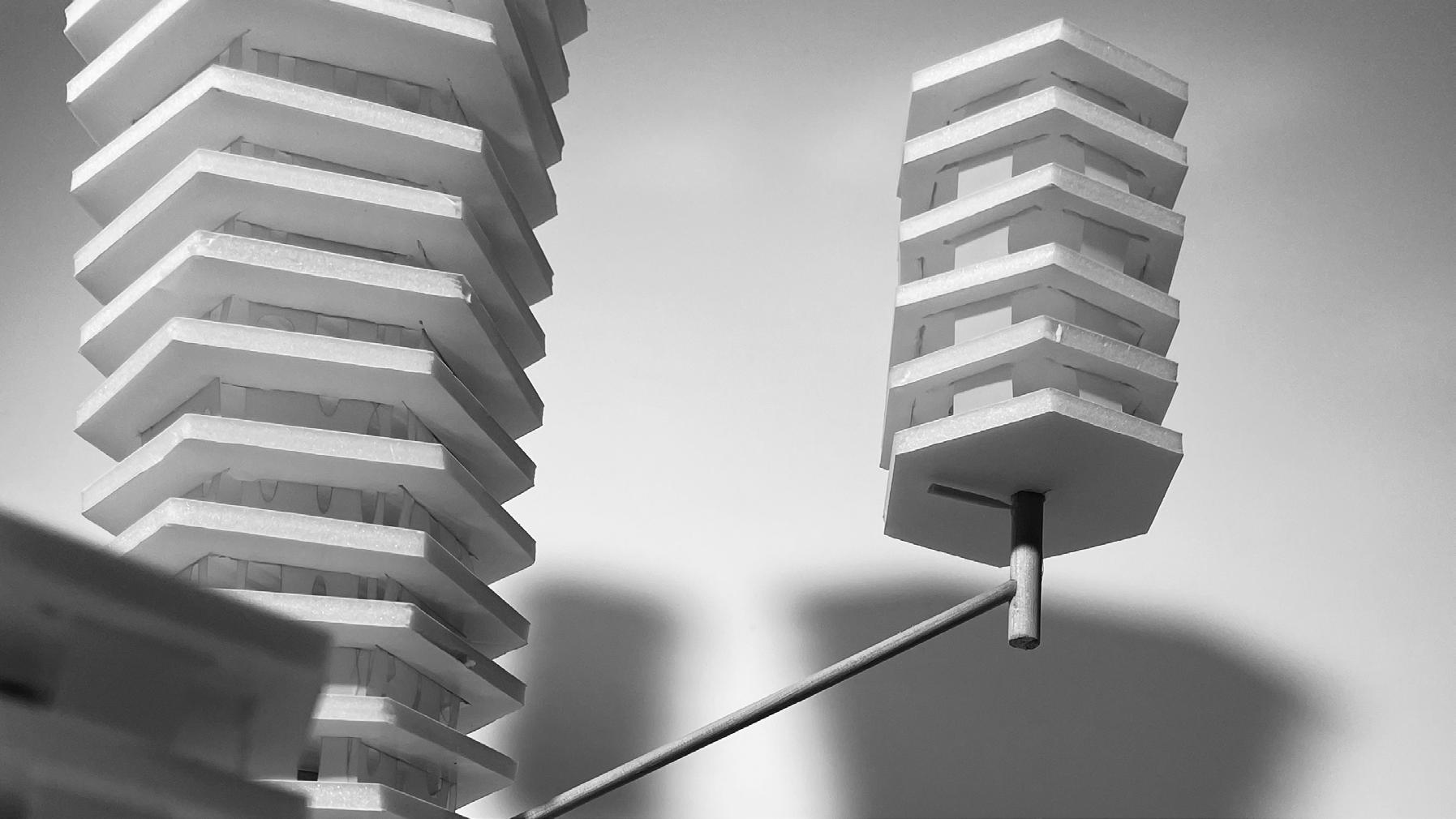
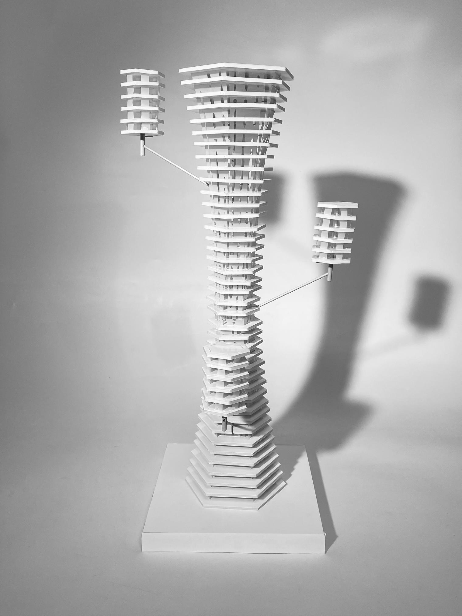
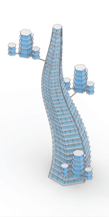
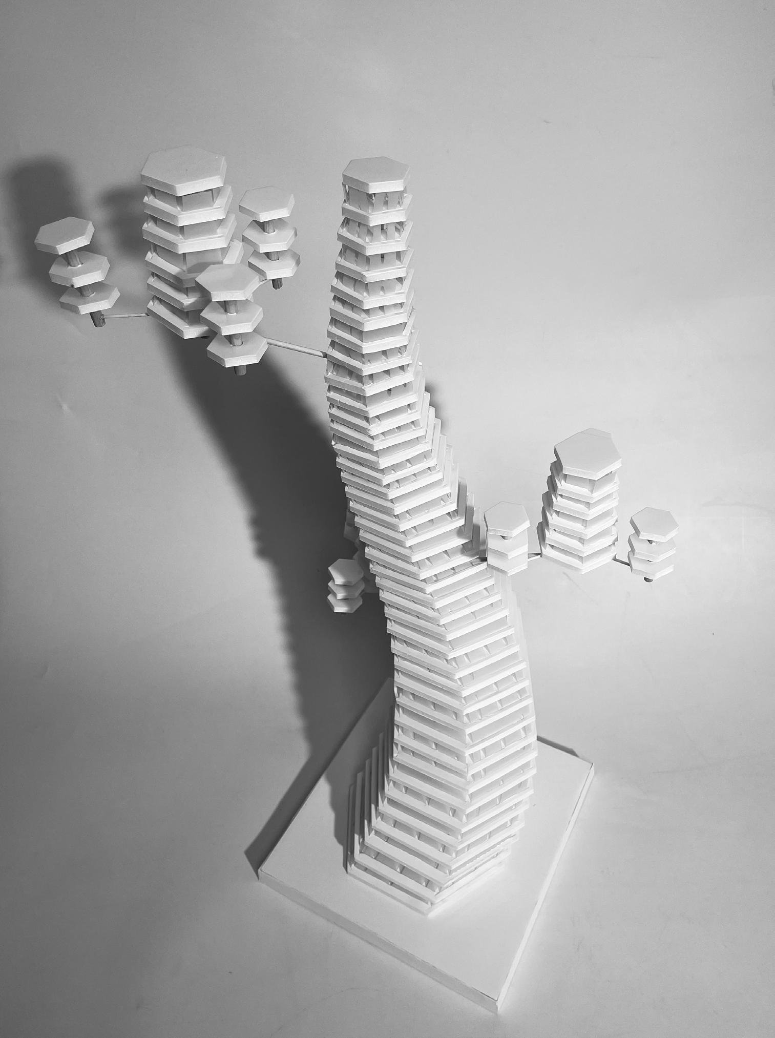
Tower 3 combines the features of both Tower 1 and Tower 2. A similar facade is employed; however, the branches have branched again, with a total of nine miniature towers branching off the secondary branches. The main tower core spirals upward, similar to the growth pattern of Tower 1. All three towers could never exist on Earth, but each would thrive on the moon.
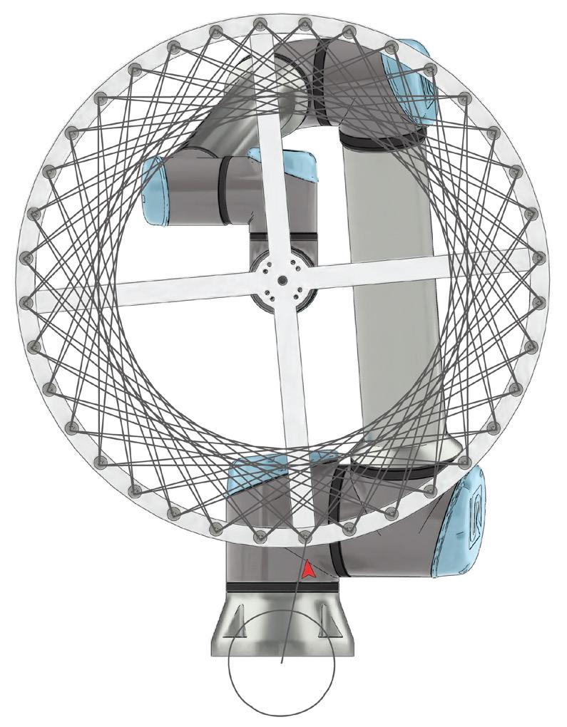
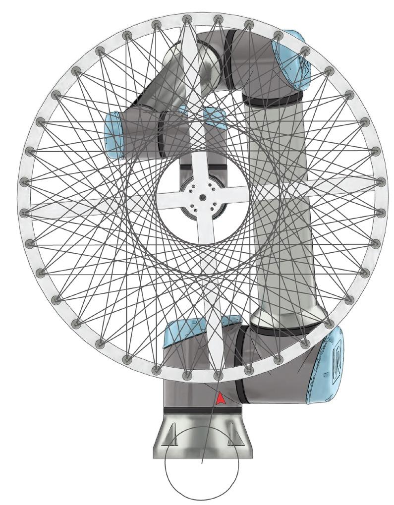
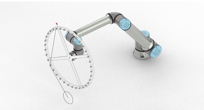
The steepness of the wedge and the interior angle dictate the central aperture of the final wind.
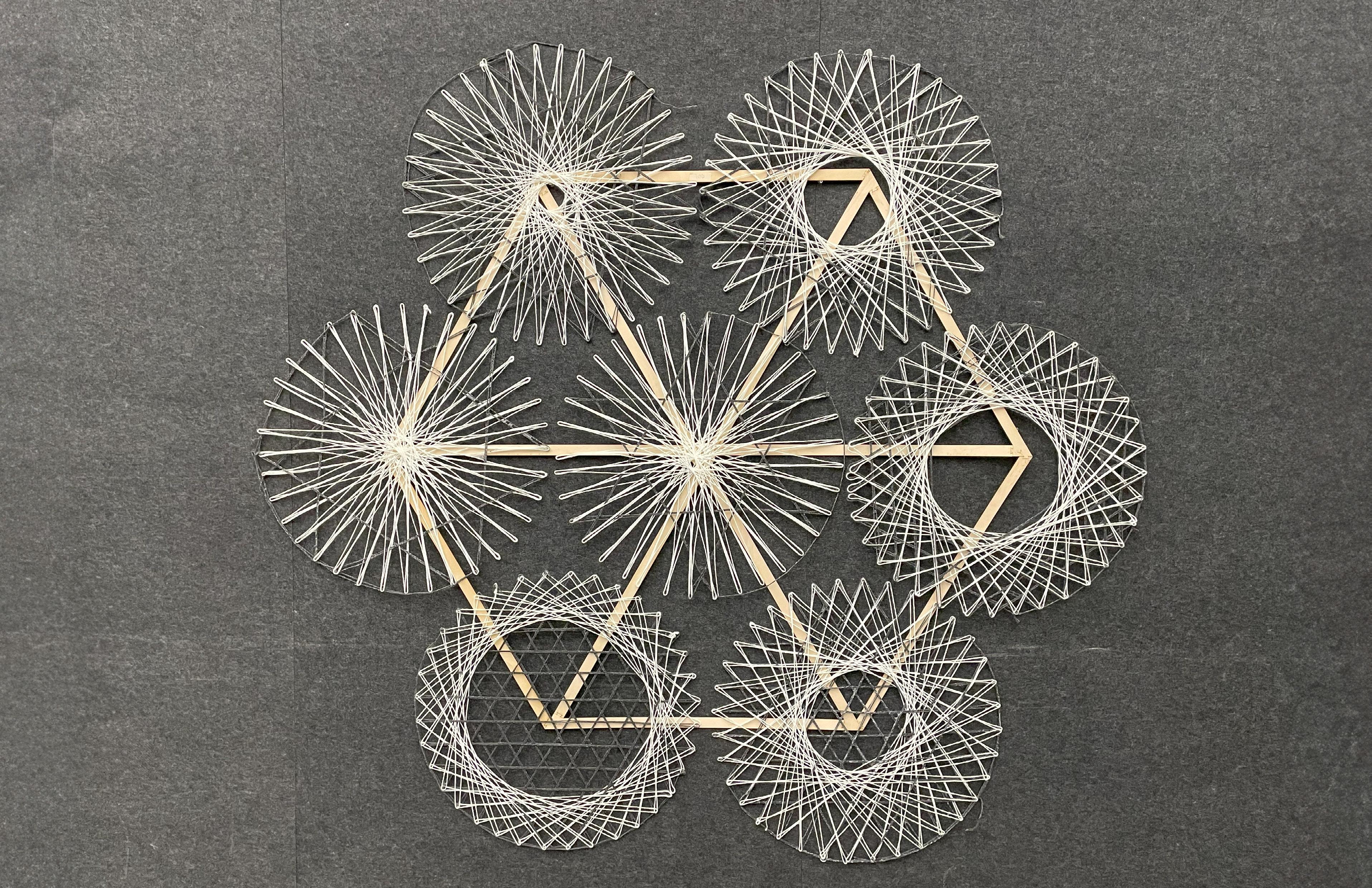
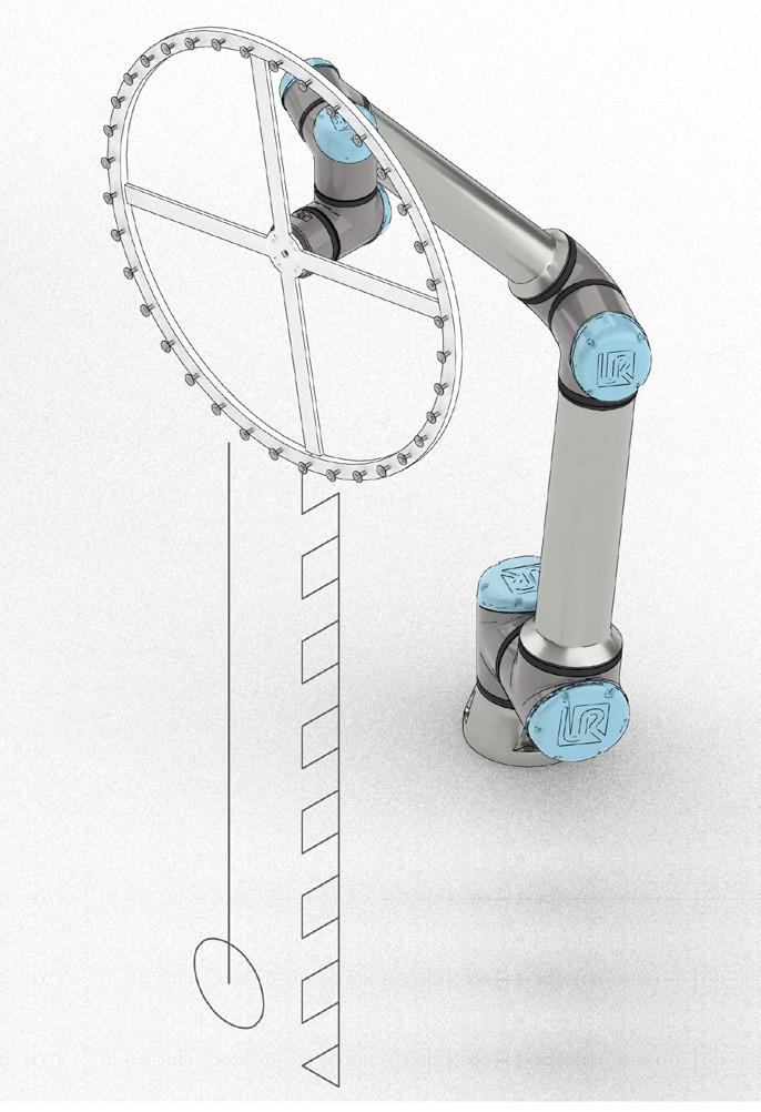
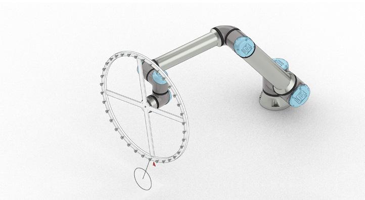
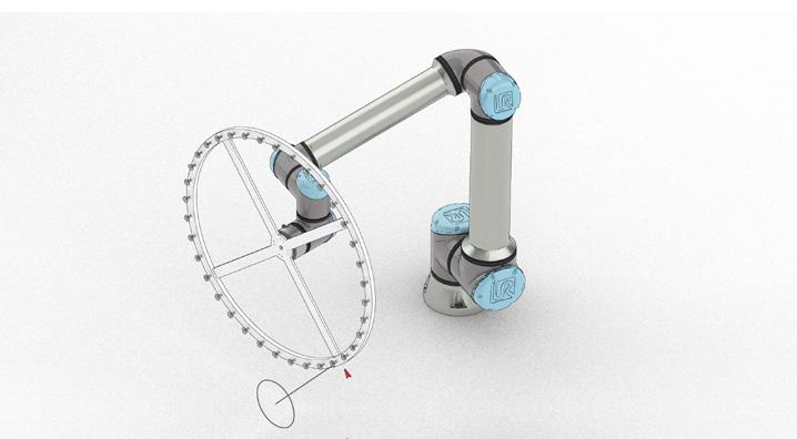
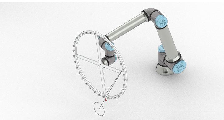
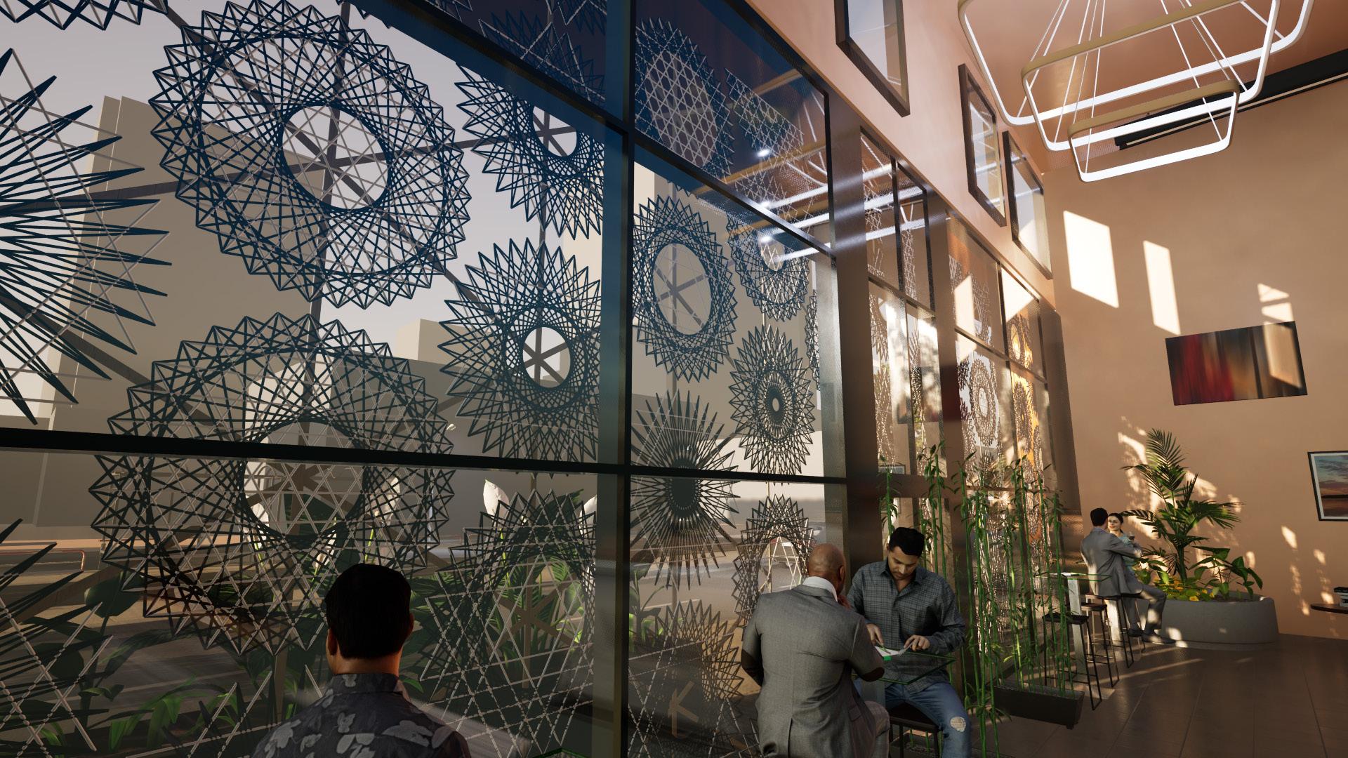
The Wind and Weave employs a UR10e robot arm to fabricate modular disks to be mounted over large window spans and act as solar shaders.
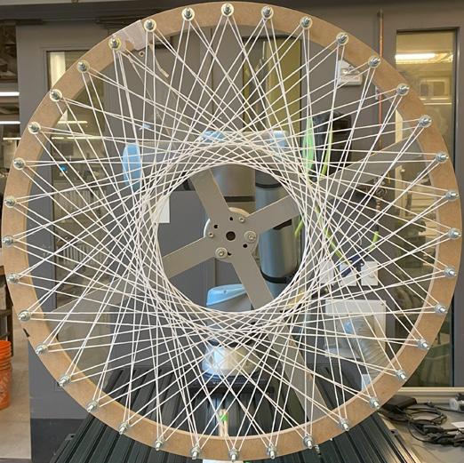
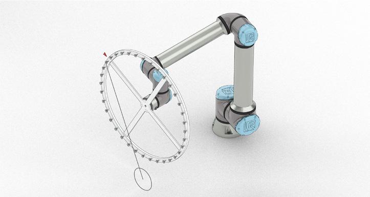
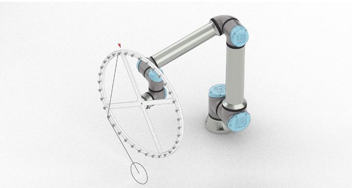
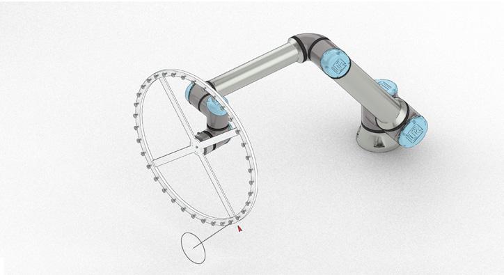
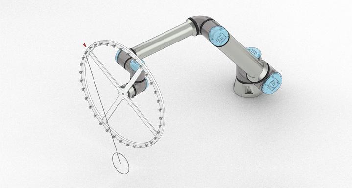
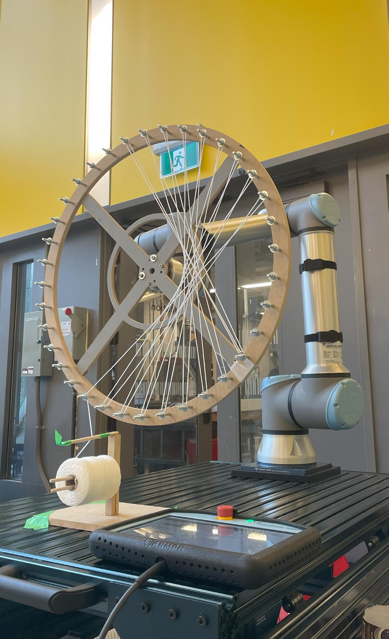
The wind is the first of two steps in creating one of the circular shader disks. First, a custom circular mount is attached to the end of the UR10e robot. String is tied off on the frame, and the 9 step pattern repeats until the entire frame has been wound into the desired pattern. The aperture in the center of the wind is variable and can be controlled by manipulating the degree of rotation that occurs in the winding process. After the wind is complete, the frame is ready for the second step, The Weave.
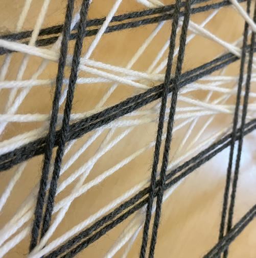
The weave is the second step and acts as the tensile strengthener to support the wind, ultimately allowing the disks to be hardened and removed from the frame. The disks are individually hardened in a glue bath, and after fully soaking and drying, they can be removed from the frame while retaining their shape. The weave process is much simpler than the wind, moving back and forth horizontally, while the frame moves vertically to feed the string between the wind. The process is repeated across the frame until the desired number of weaves is reached.

Each wedge is the result of the 9 step process, which is repeated 72 times.
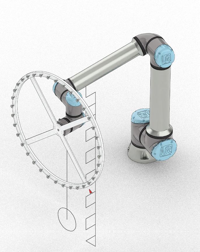
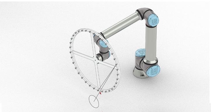
Step 1
String starts tied off on bottom bolt, arm is in forward position past the string feeder
Step 4
Bracket rotates 175° clockwise to form first edge of the wedge
Step 7
Arm retracts to be able to freely rotate without hooking string
Step 2
Bracket rotates 15° counter clockwise to hook string
Step 3
Arm retracts to be able to freely rotate without hooking string
Step 5
Arm moves back forward in preperation to hook more string
Step 6
Bracket rotates 15° clockwise to ensure string is hooked
Step 8
Bracket rotates 170° degrees counter clockwise to form second edge of the wedge
Step 9
The arm moves the bracket directly above the string feeder marking the end of the loop, and is ready to repeat
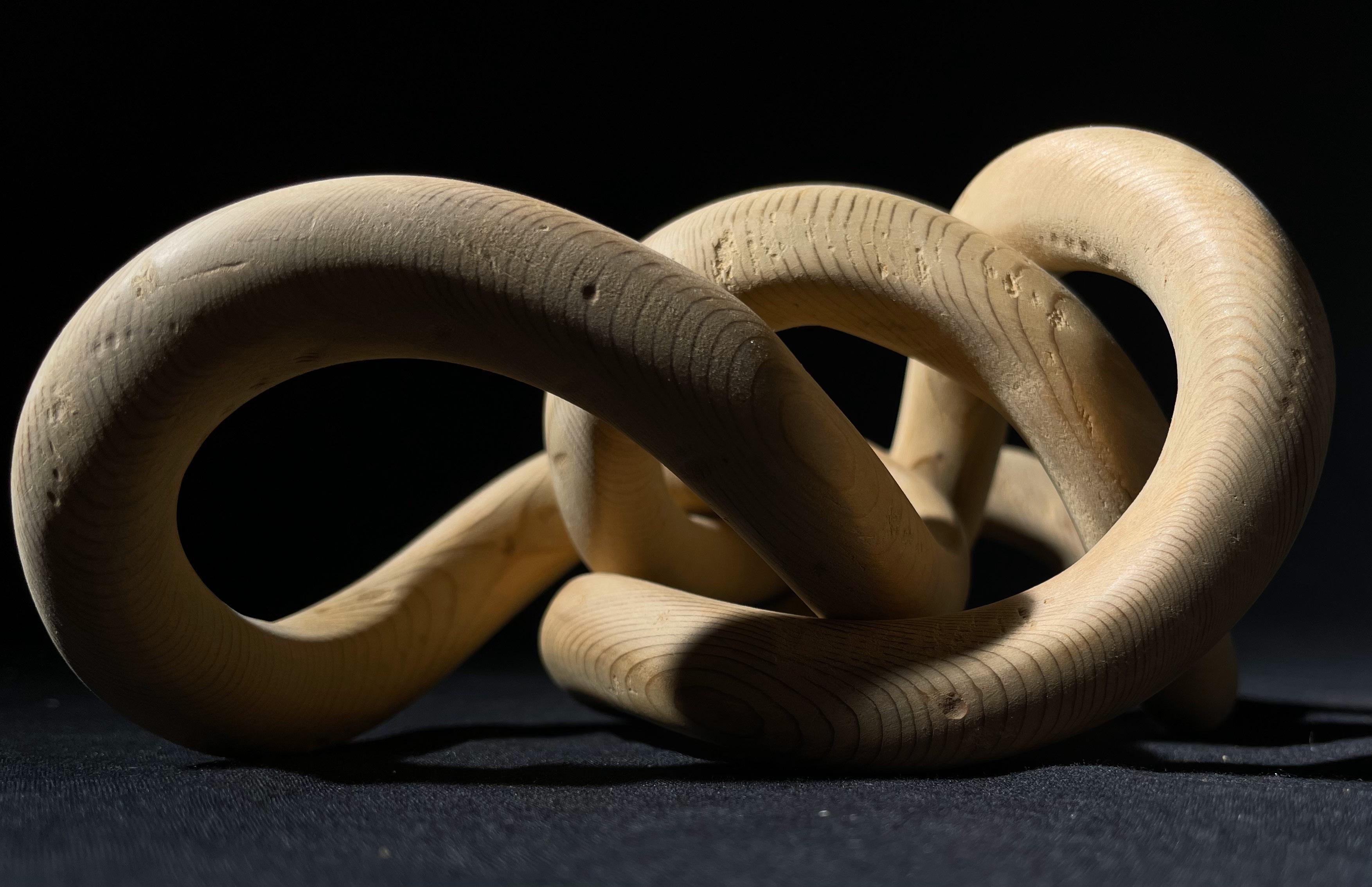
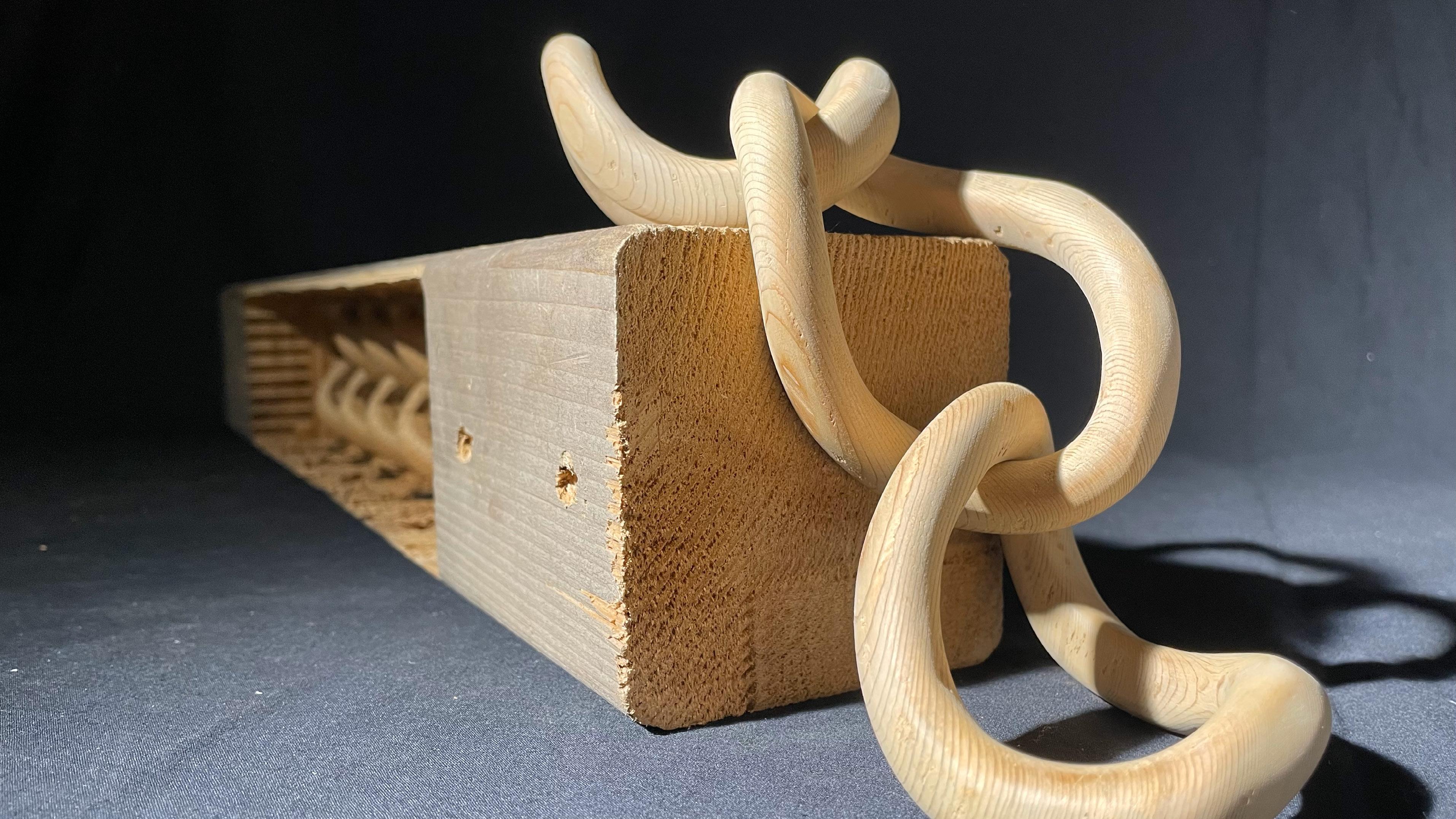
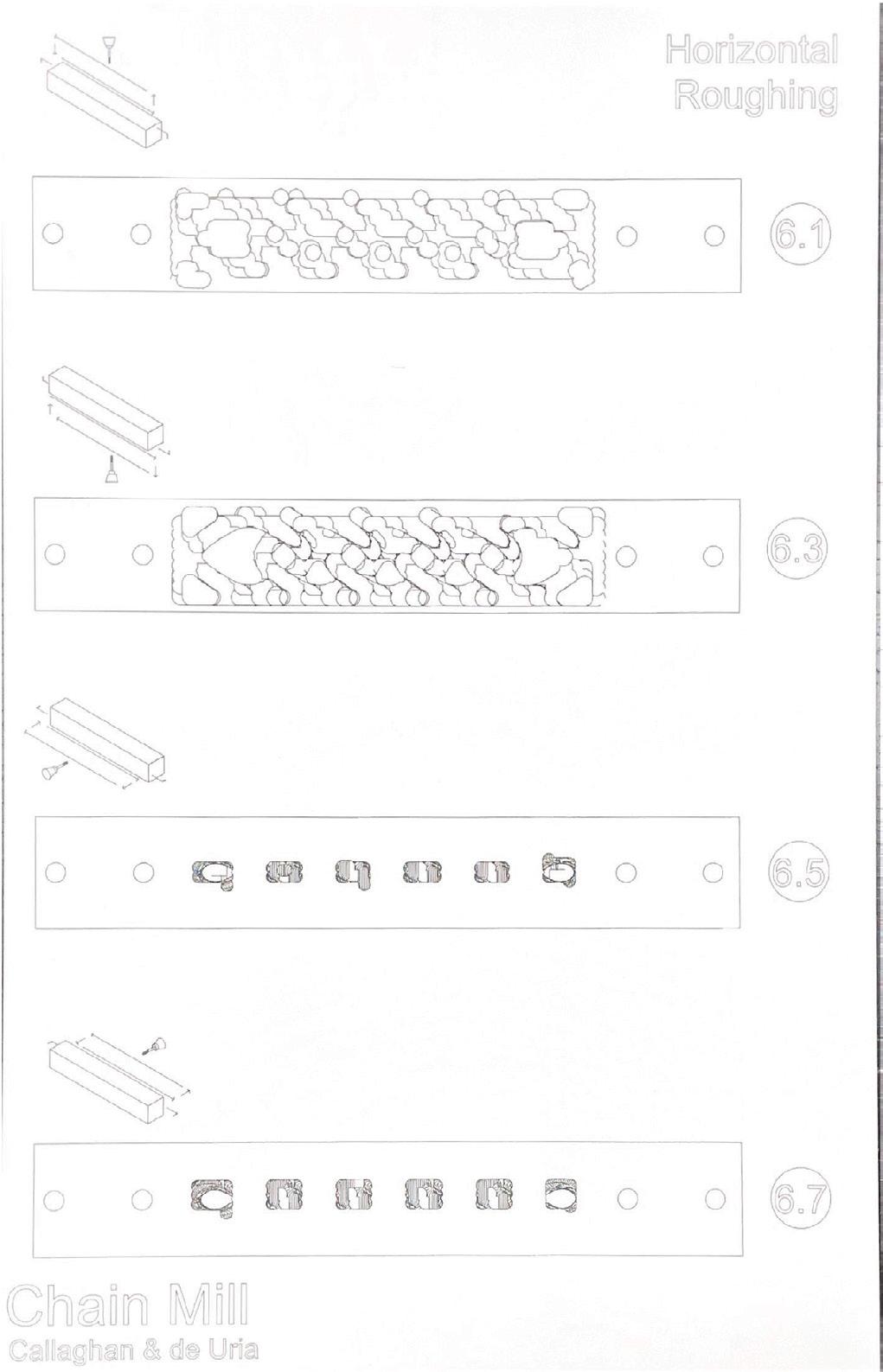
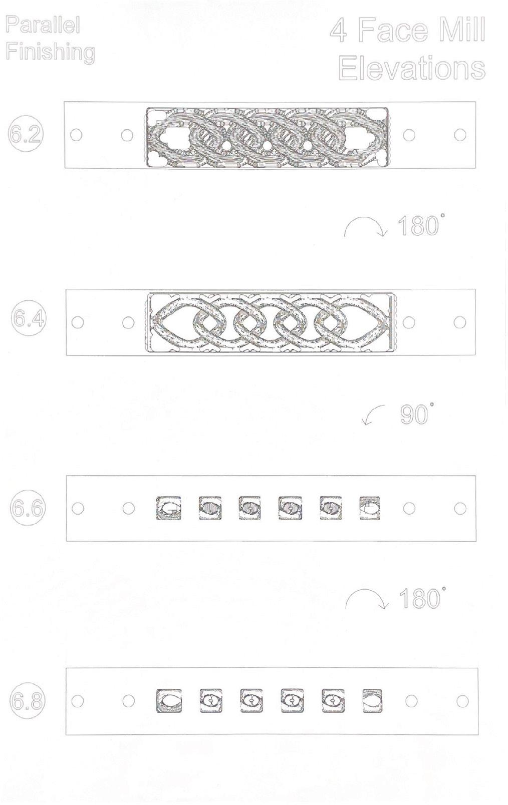
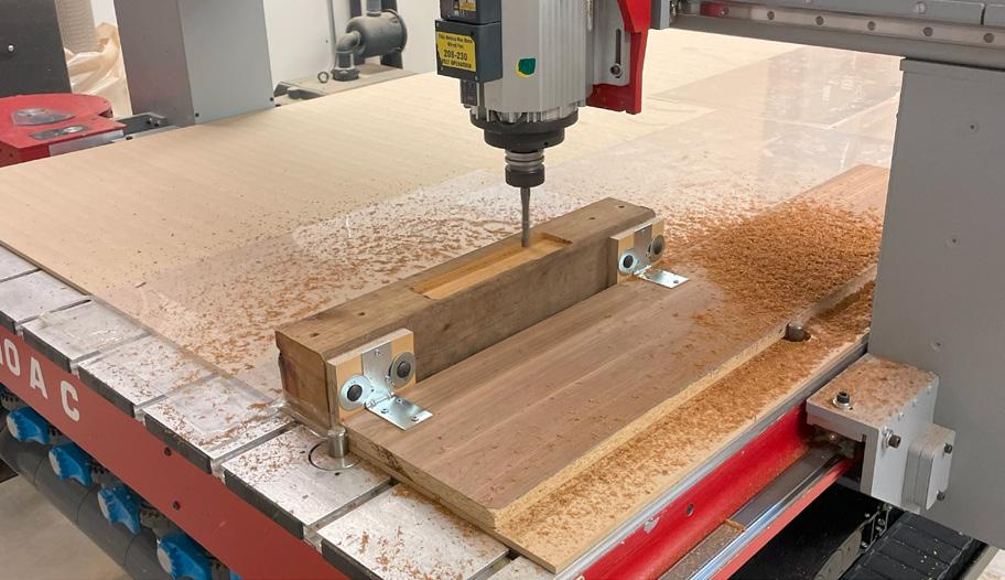
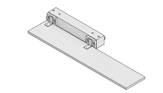
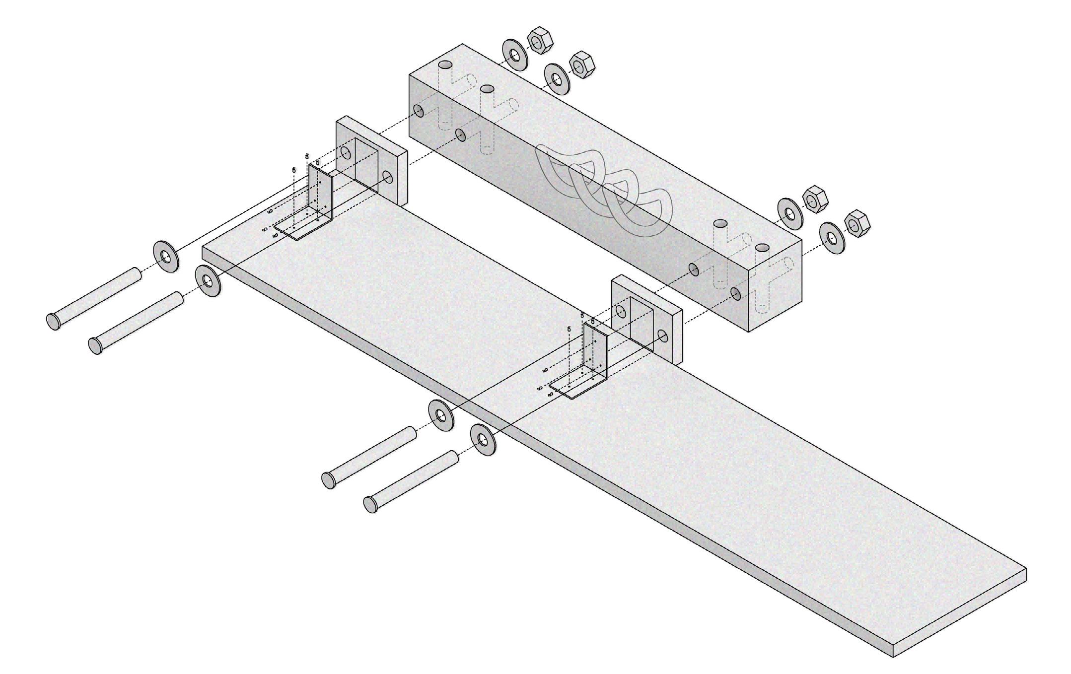
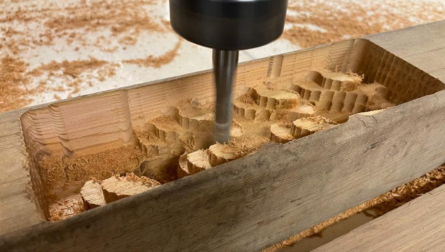
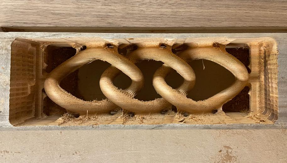
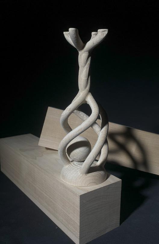
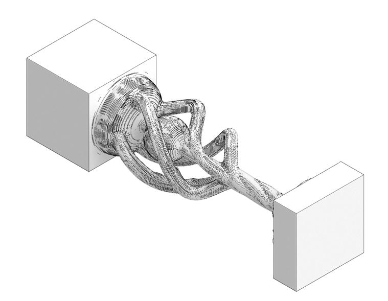
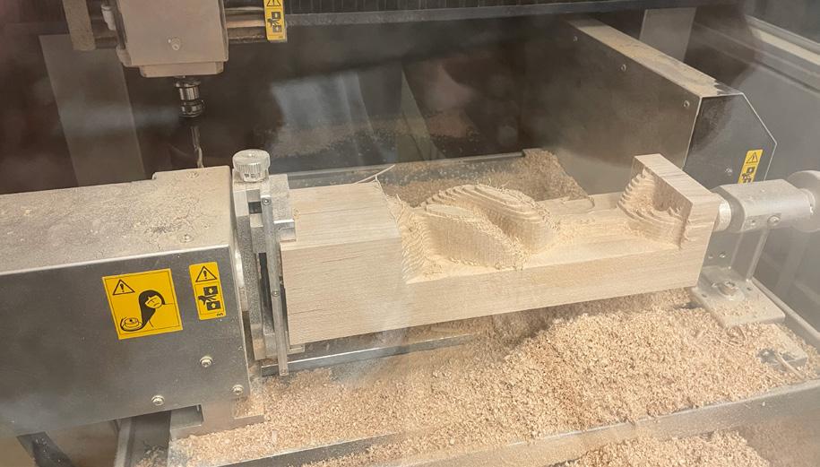
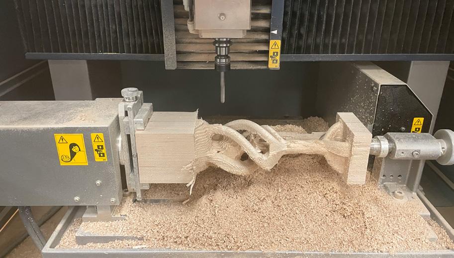
The chain employs a CNC mill to cut into a 4x4 cedar post and form the resulting chain. A custom jig was designed to hold the post during the milling process and allowed the post to be turned so all four faces could be milled. After the CNC is finished, the chain is still attached to the post and needs to be removed and finished by hand.
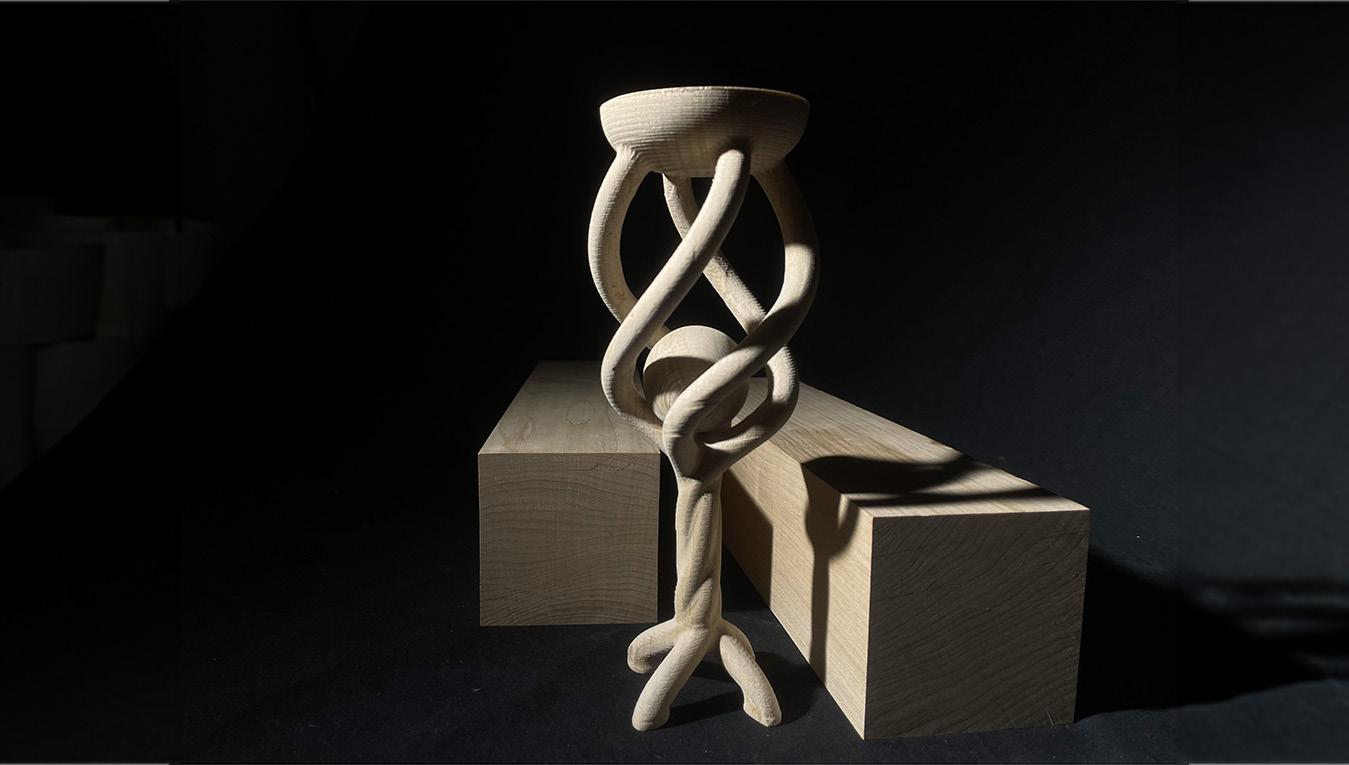
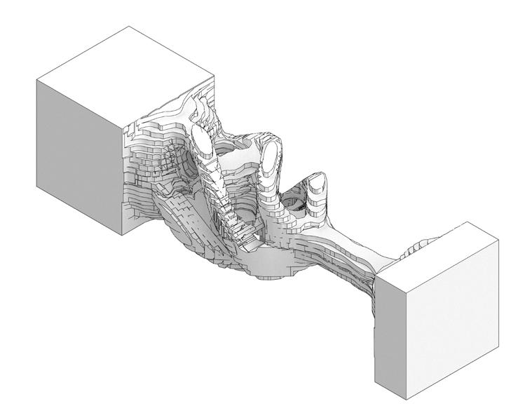
The sphere utilizes a 3-axis CNC mill. The machine allows the stock to be milled on any face without the use of a jig. This made it possible to mill the ball inside the cage from a single piece of maple, where the entirety is unbroken and originates from a single stock. A single support rod was needed to ensure the ball was stable during milling, and it was carefully removed by hand afterward to leave the ball loose but still encaged. The top and bottom blocks were also removed by hand after milling, as they are needed during the process to hold the stock.


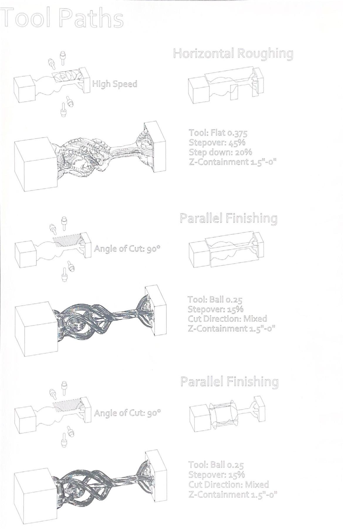
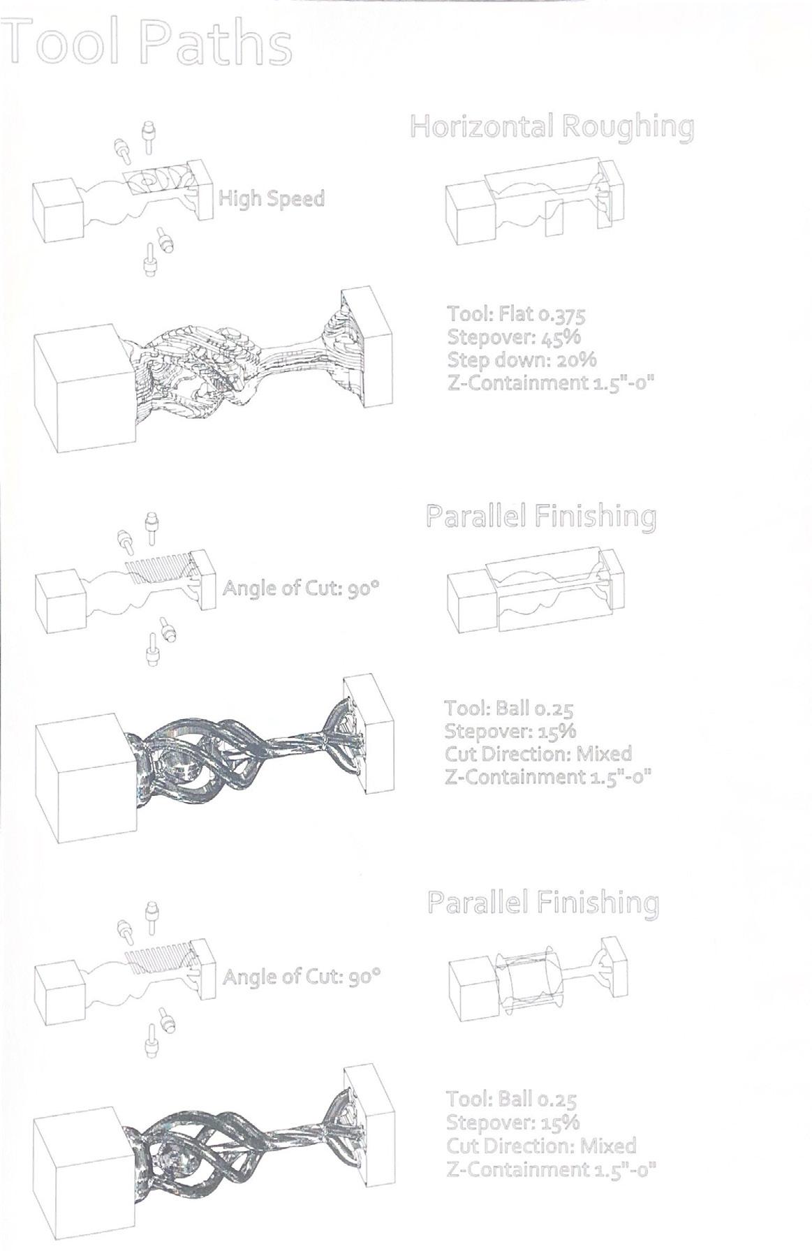

Parallel Finishing Tool: Ball 0.25
Stepover: 15%
Cut Direction; Mixed
Z-Containment 1.5”-0”
Parallel Finishing Tool: Ball 0.25
Stepover: 15%
Cut Direction; Mixed
Z-Containment 1.5”-0”
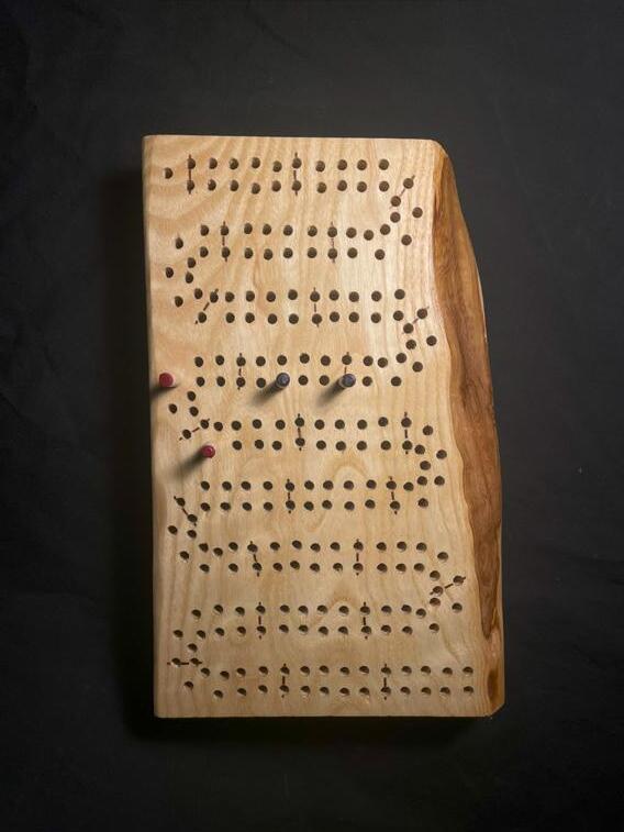
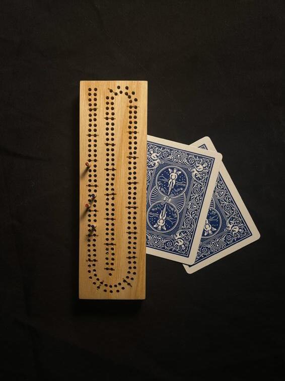
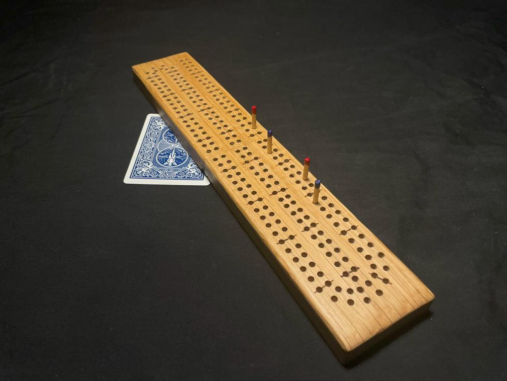
Each of these woodworking pieces is a personal project I undertook in my free time.
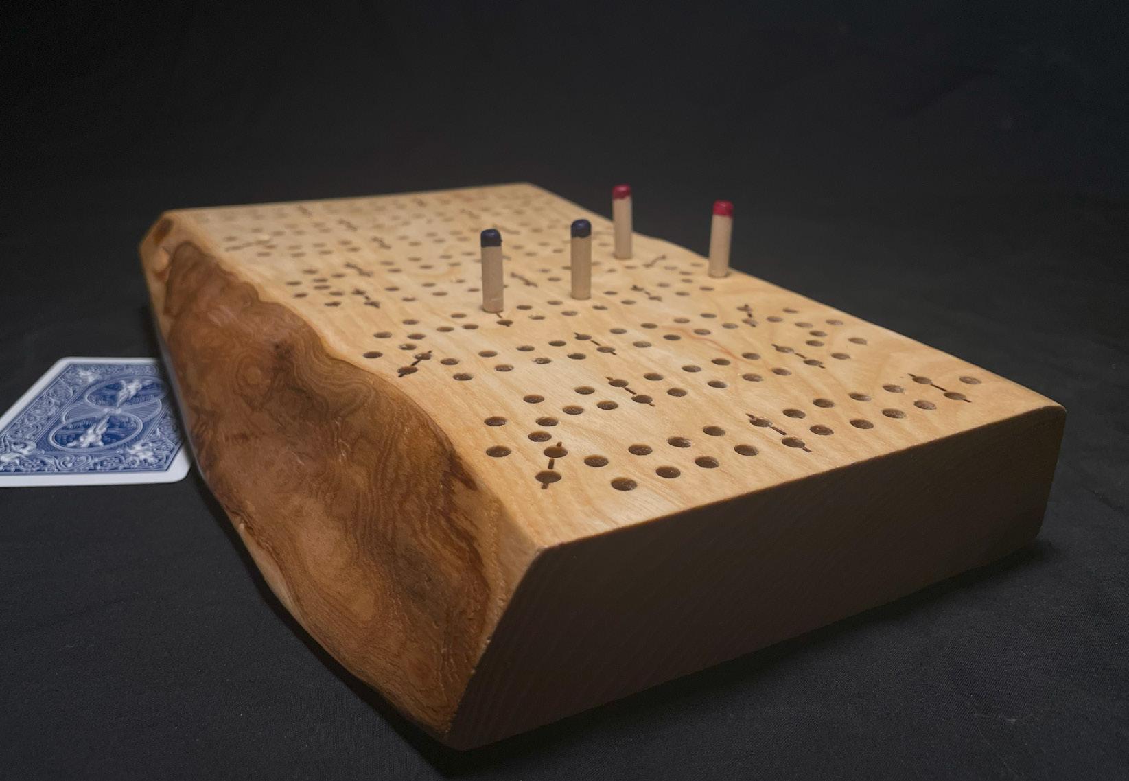
Boards:
The cribbage boards are made from offcut pieces of wood I found discarded, and all 241 holes on each board were drilled by hand on a drill press.
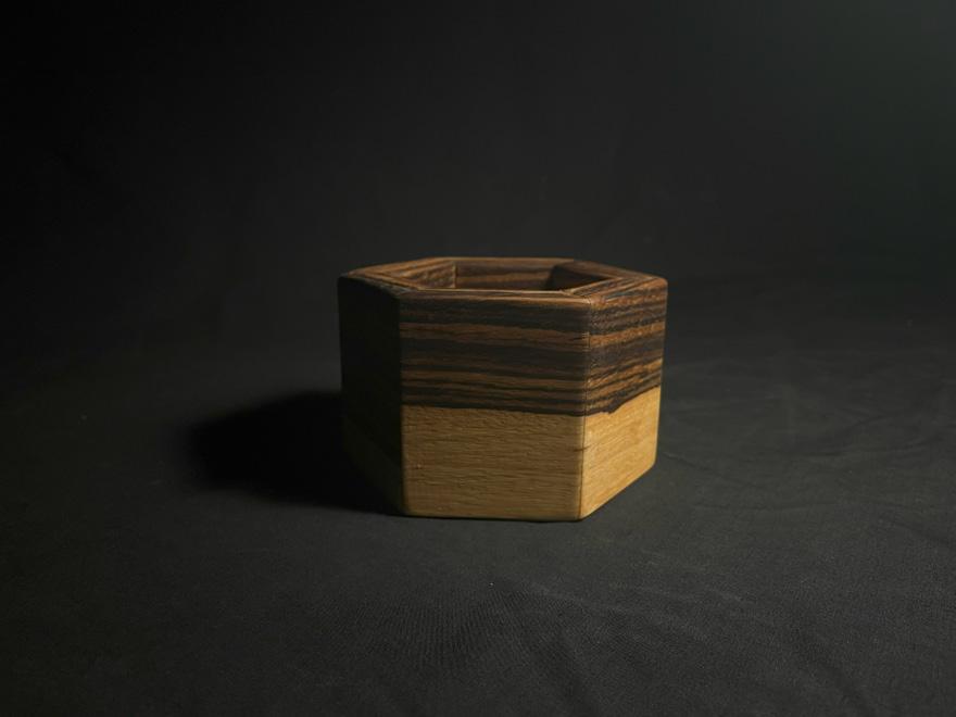
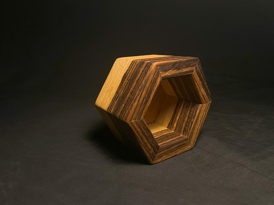
Pot:
The pot is made from zebra wood, with consideration taken to ensure the grain runs continuously around the exterior.
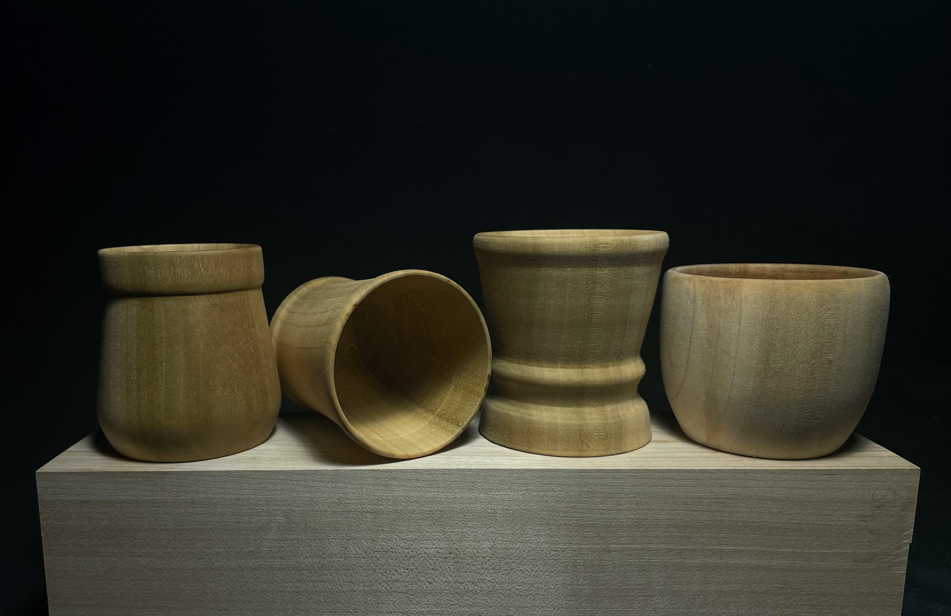
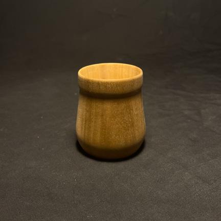
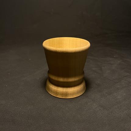
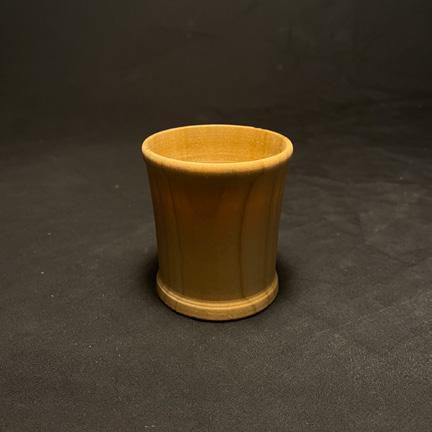
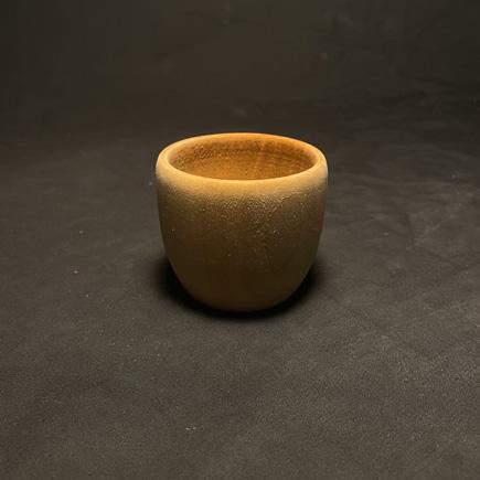
Cups:
The cups were made from a single stock of white oak. A lathe was used to turn each cup, each of which now serves as a vessel for espresso.
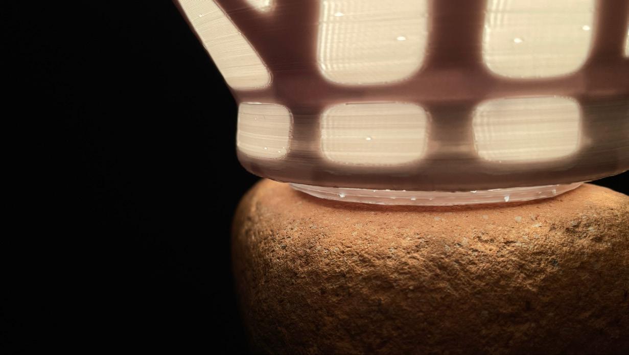
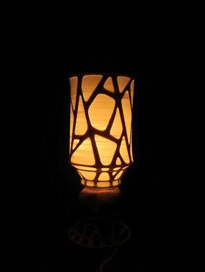
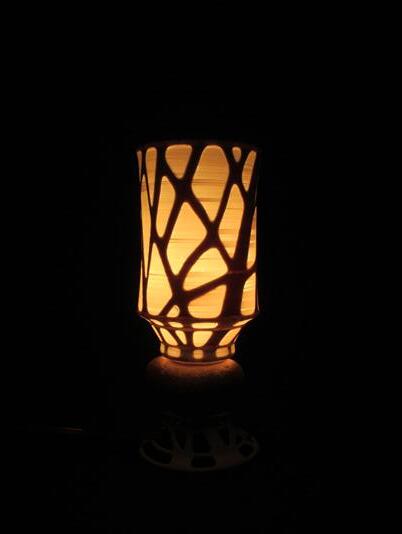
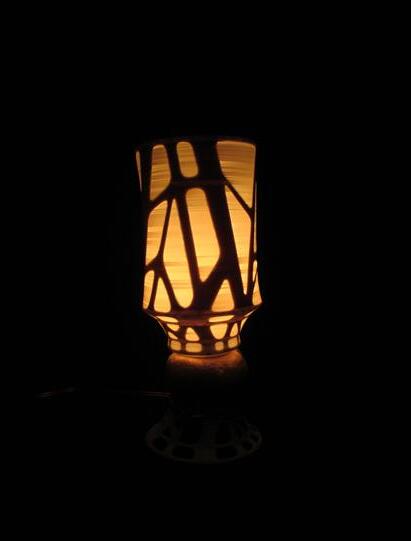
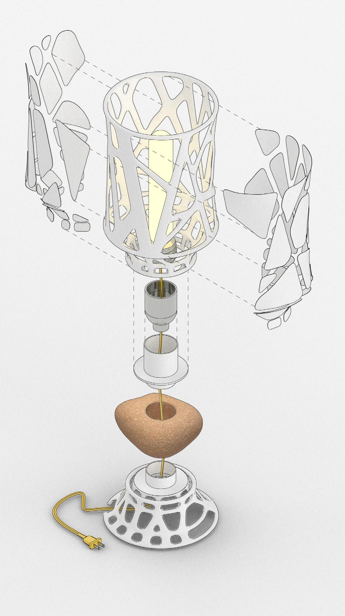
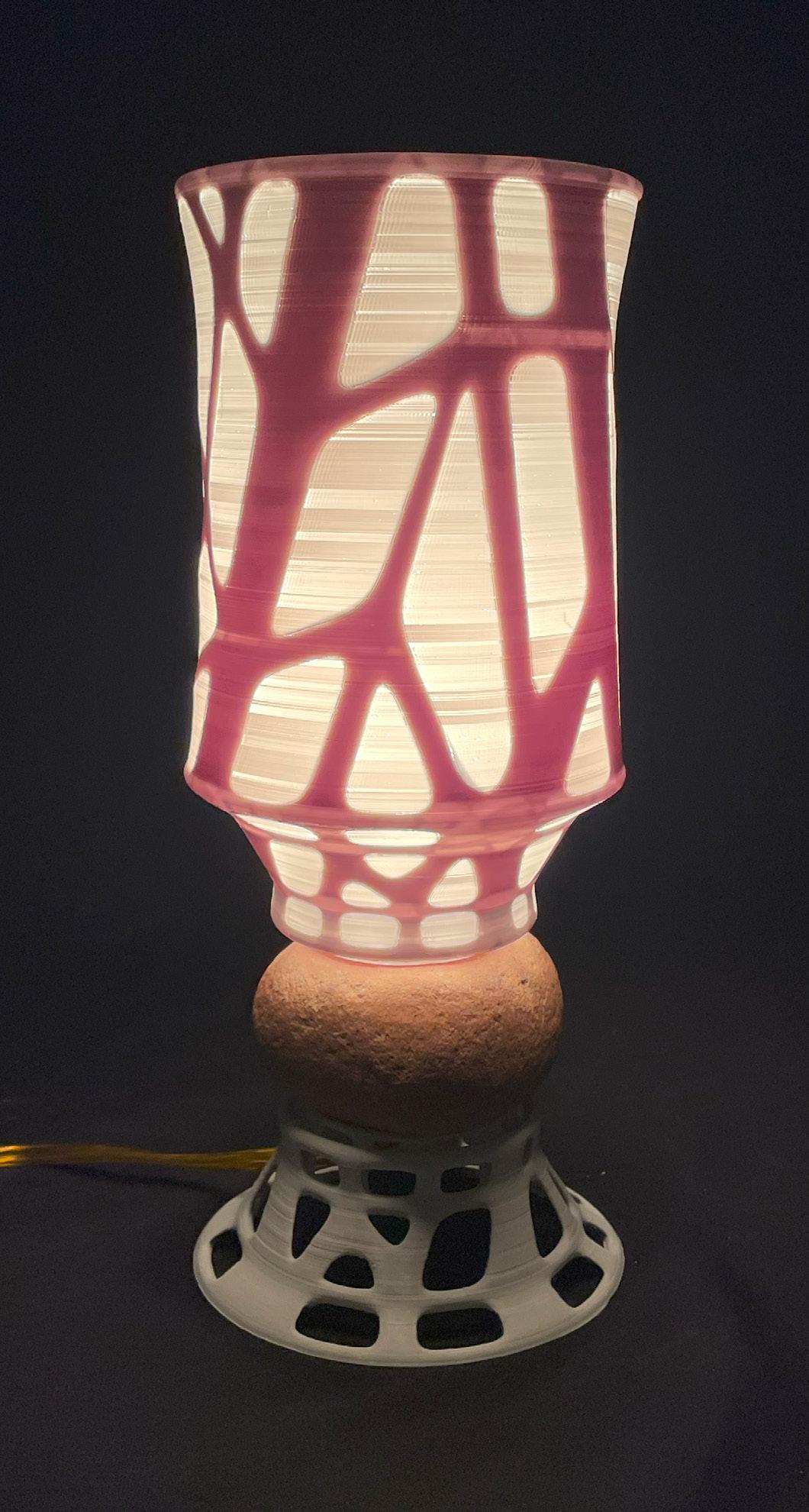
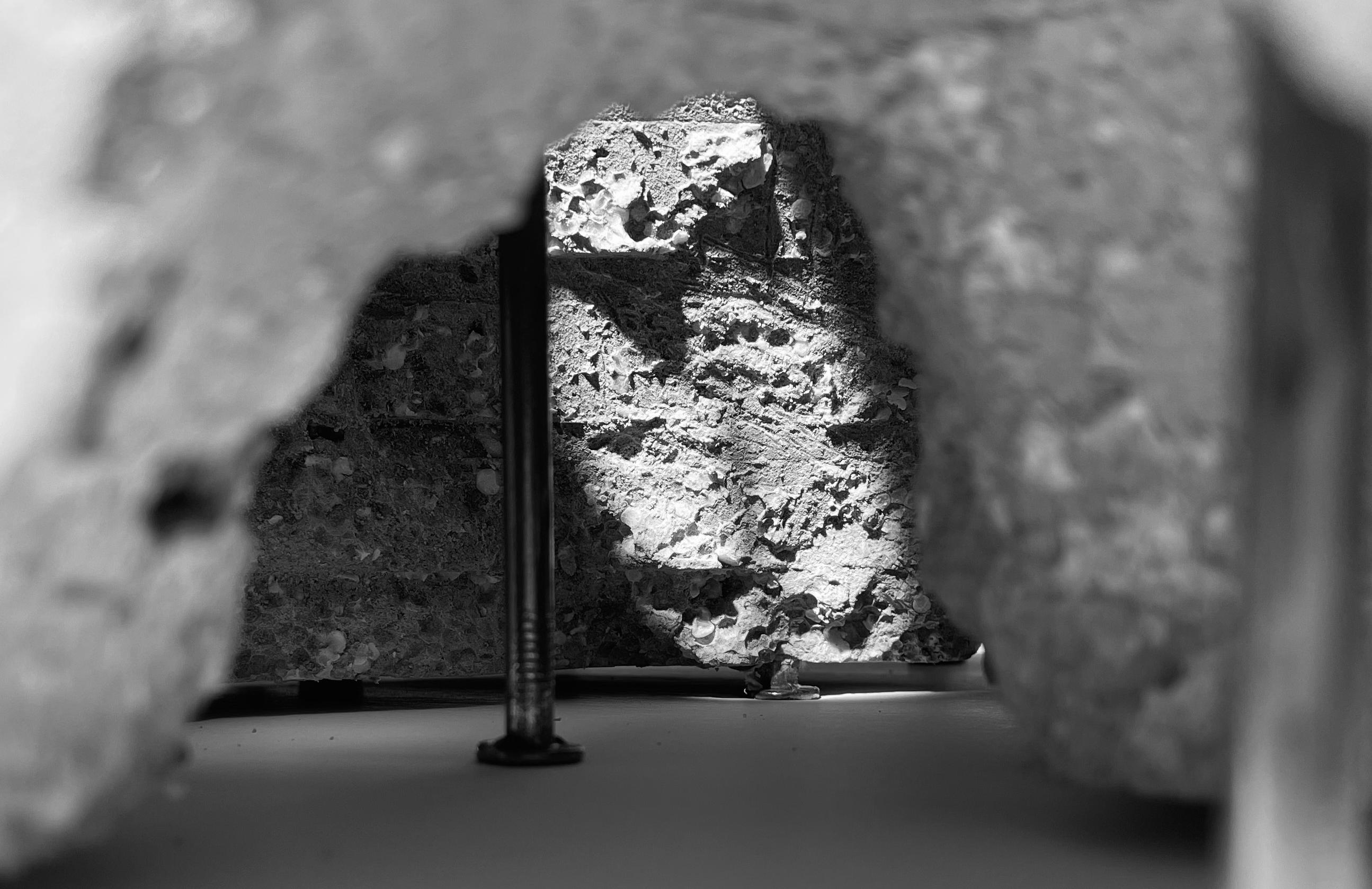
The brick lamp is also a personal project, completed in my free time.
The lamp leverages modern technologies alongside natural elements. Both the shade and base were 3D printed, with extra consideration given to the shade to ensure the difference in print width would allow light through. Printed in white PLA, these two plastic components contrast with the worn brick that sits between them. I found the brick on the shore of Tommy Thompson Park, where it had been washed over by the water, resulting in the smooth, rounded brick. The central hole made it perfect for a slotted assembly through which the wiring could run.