Lucas Talbot
Project A - The Edge
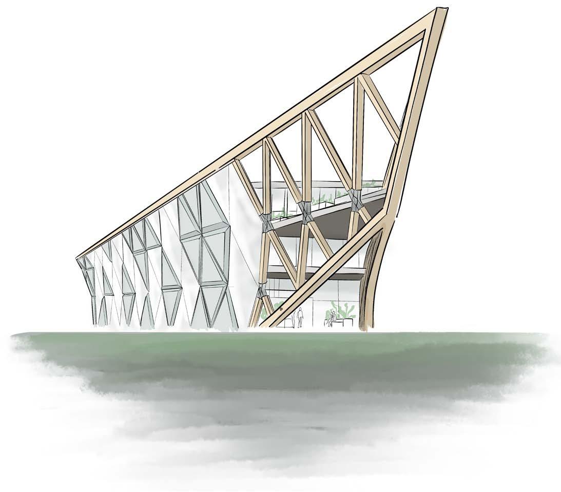
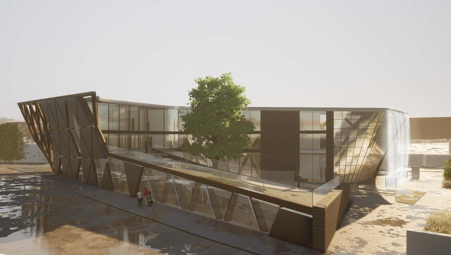
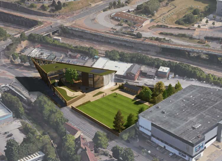
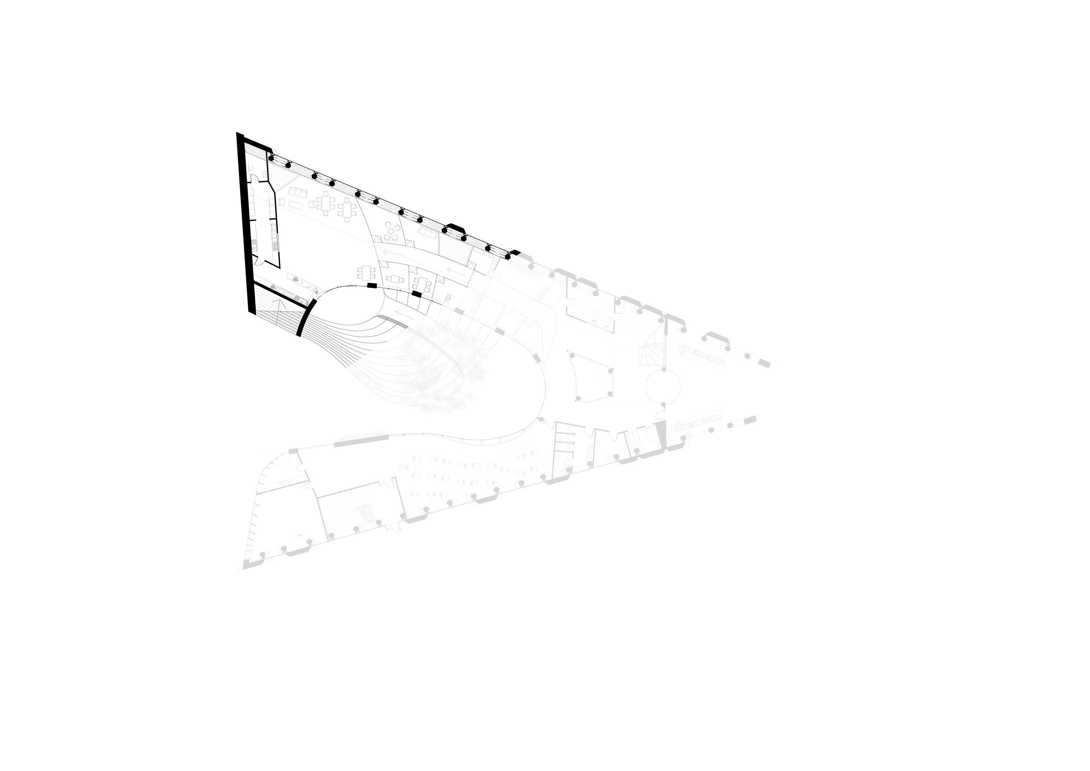
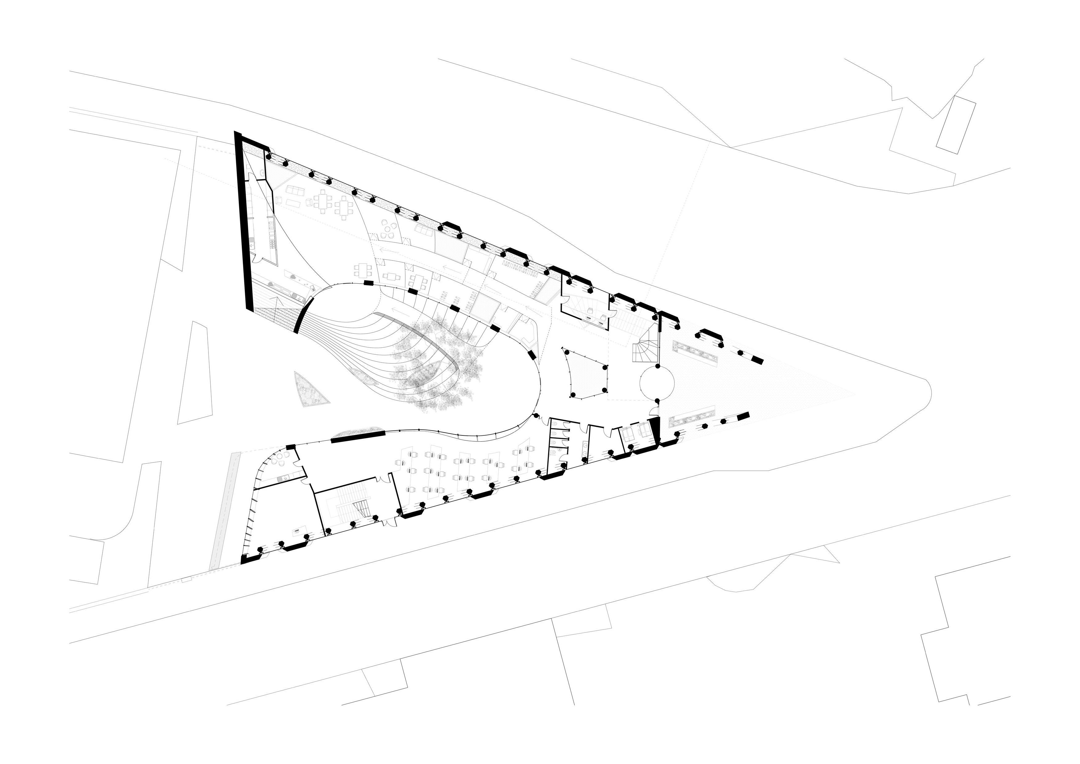
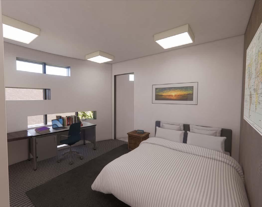
The proposed development is a new multi-use facility to serve as the new Age UK headquarters. Not only providing office spaces for Age UK staff, this building will function as a central hub for elderly people in the area as well as charity shops, a cafe and other social facilities promoting physical and mental well-being. The building will also accommodate a small number of residents. The design integrates green spaces throughout and includes plans to refurbish the derelict bowls court located to the south of the site.
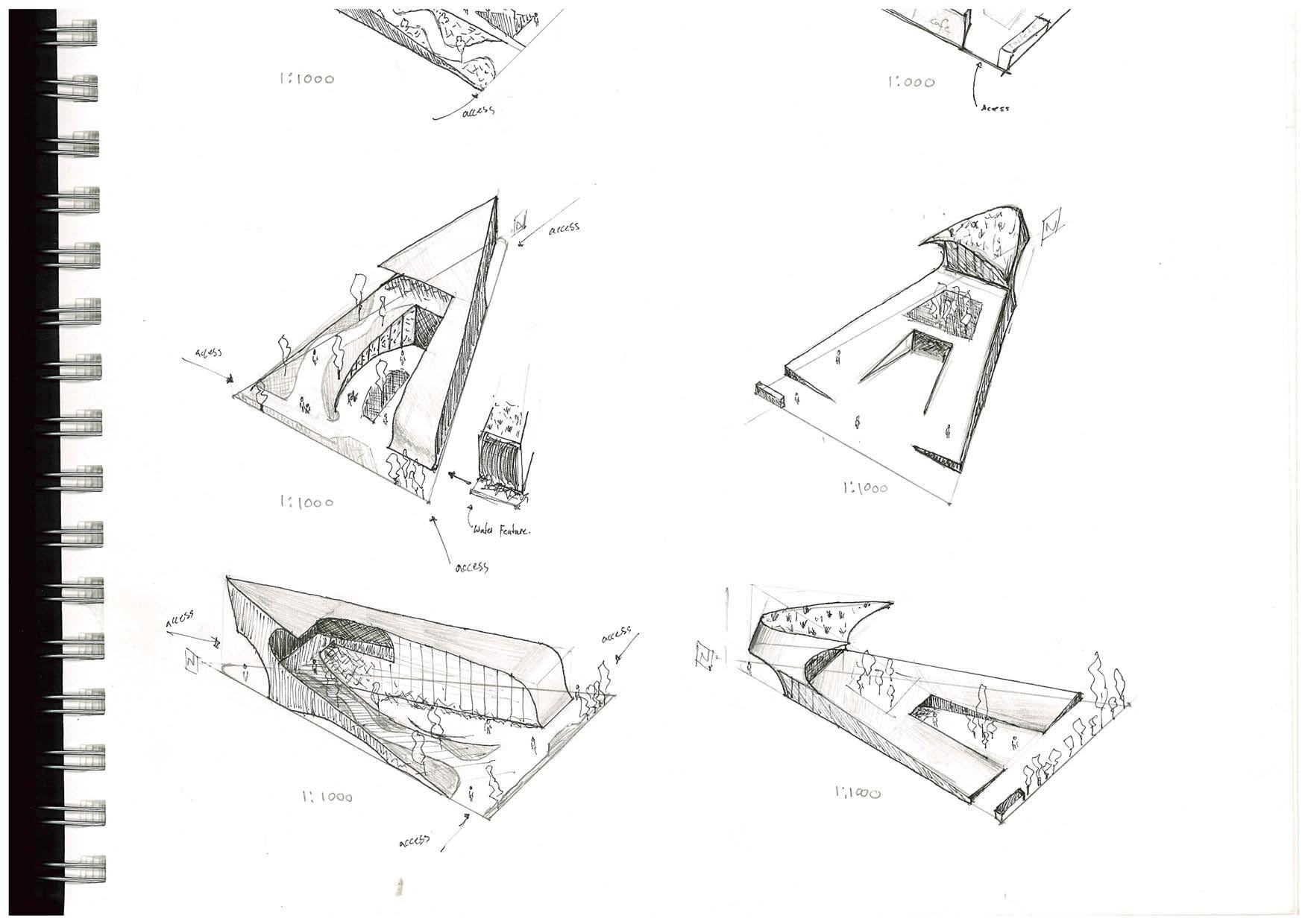
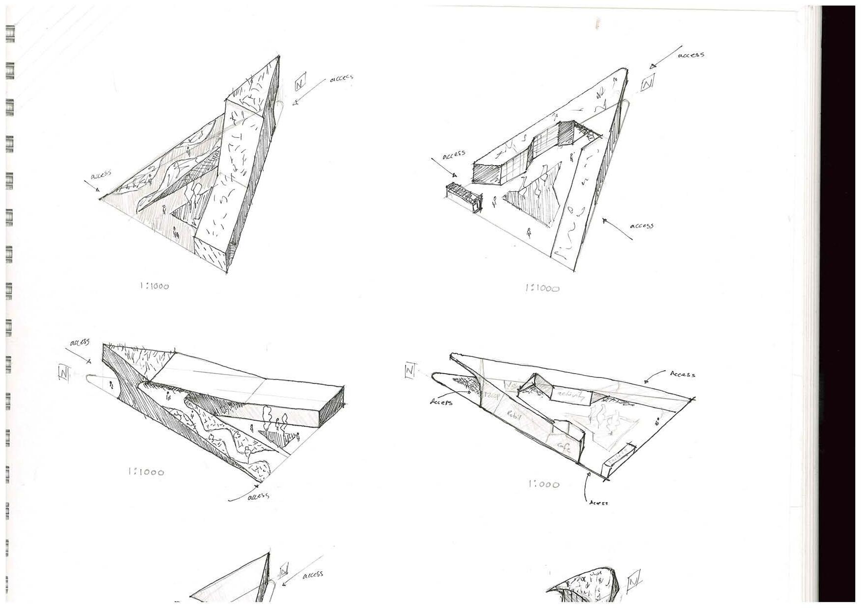
Concept Sketches
Concept Sketches
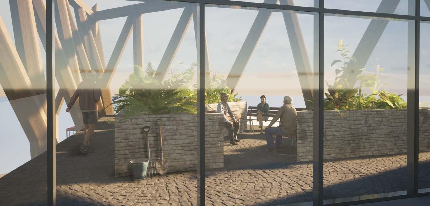
Rooftop Garden Proposed
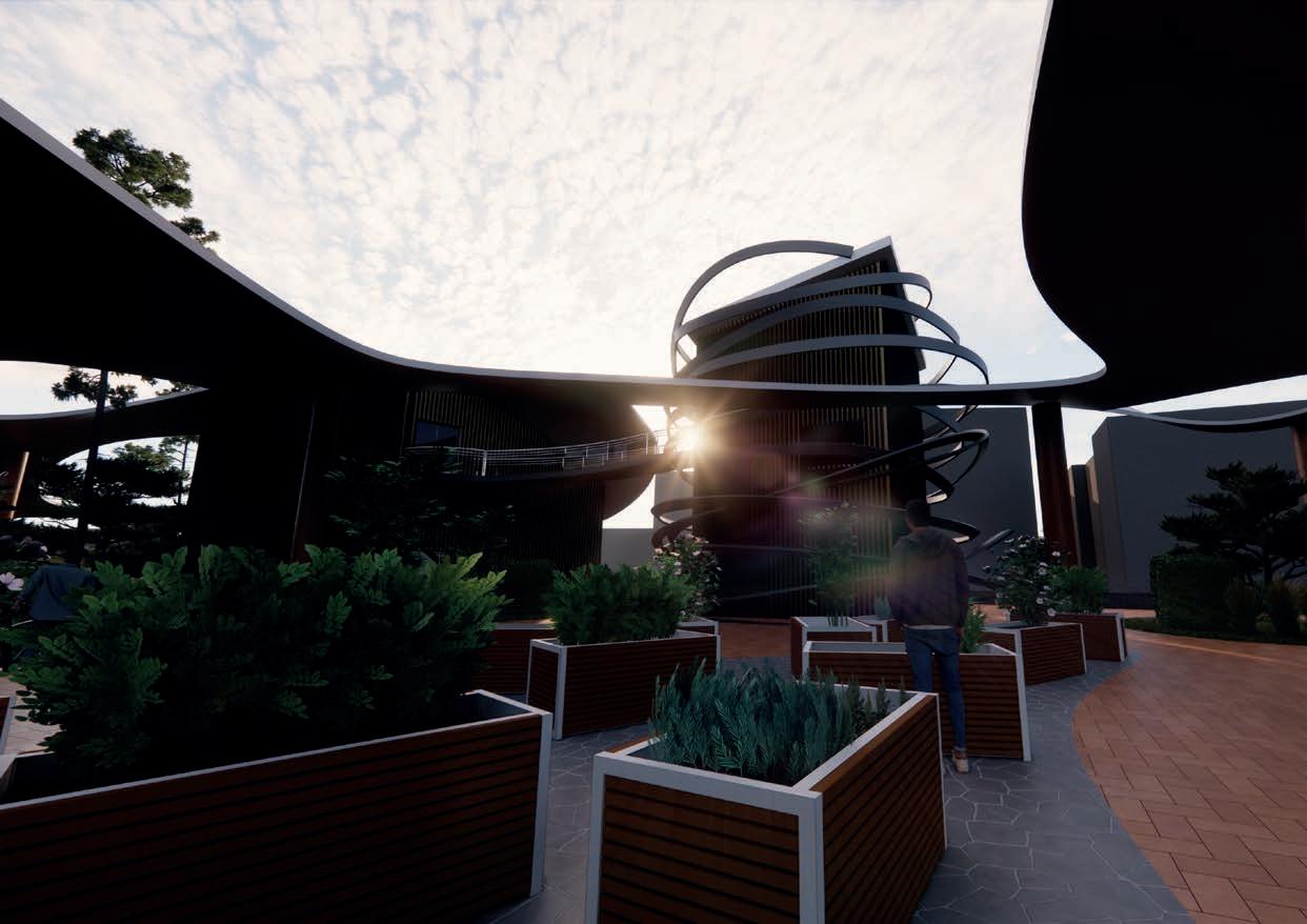
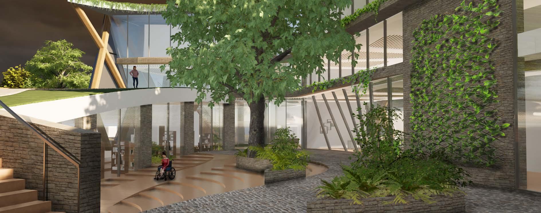
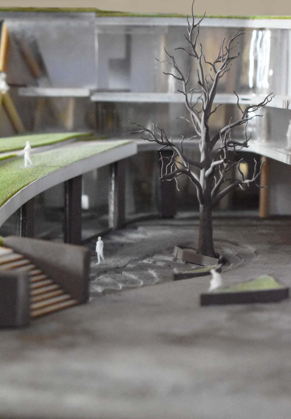
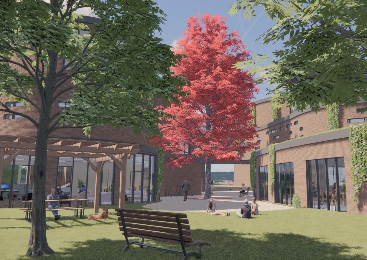
Courtyard
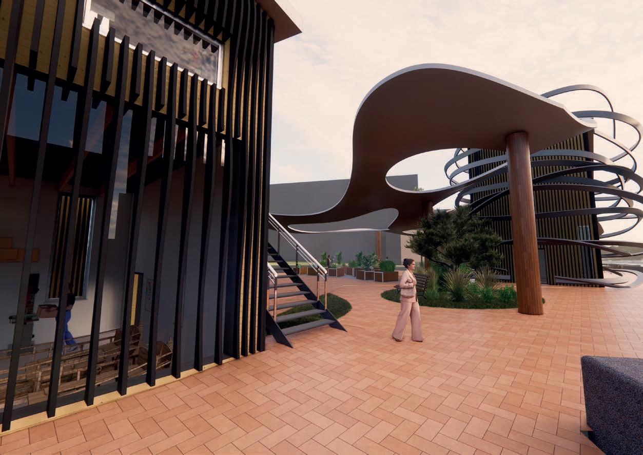
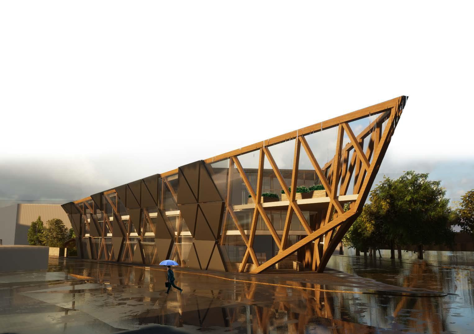
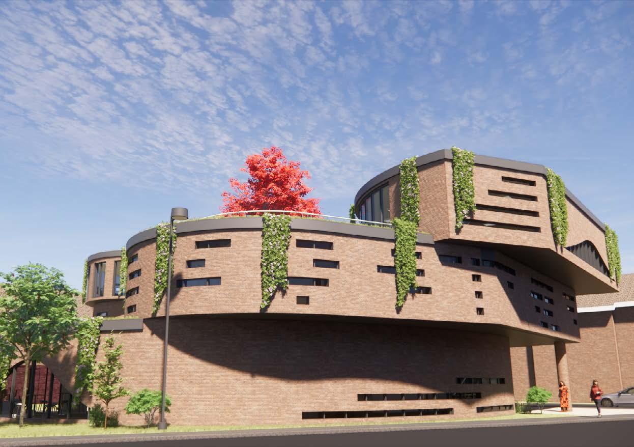
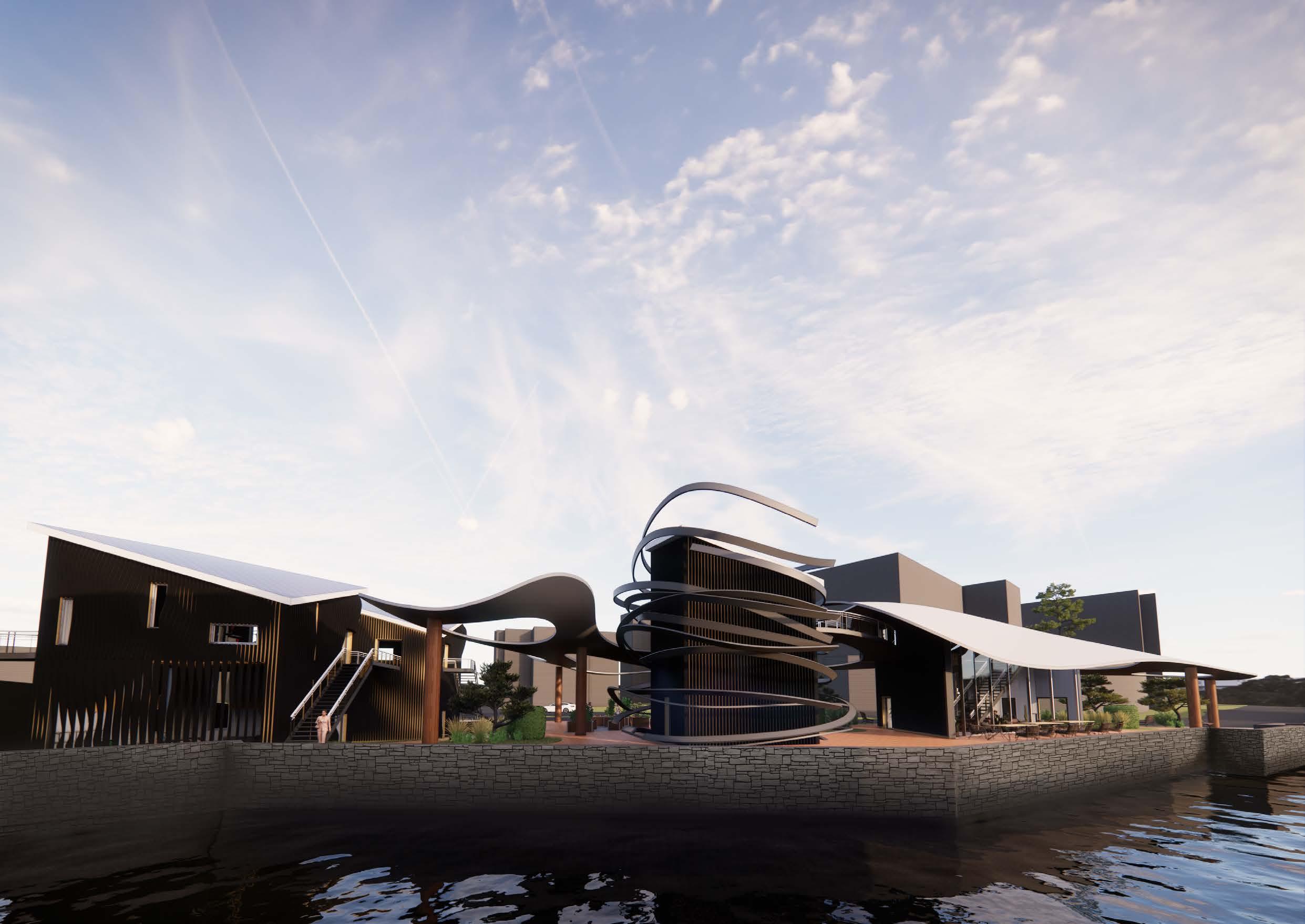
Exterior
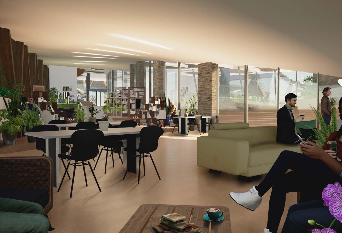
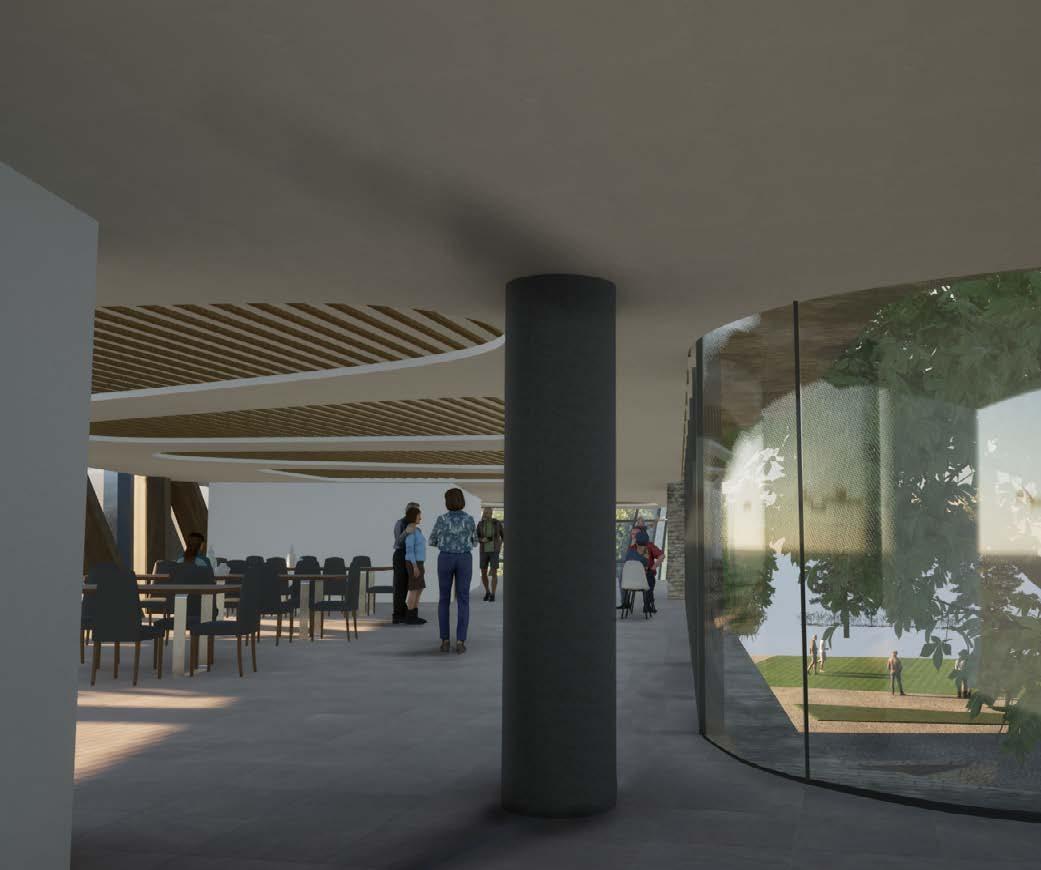
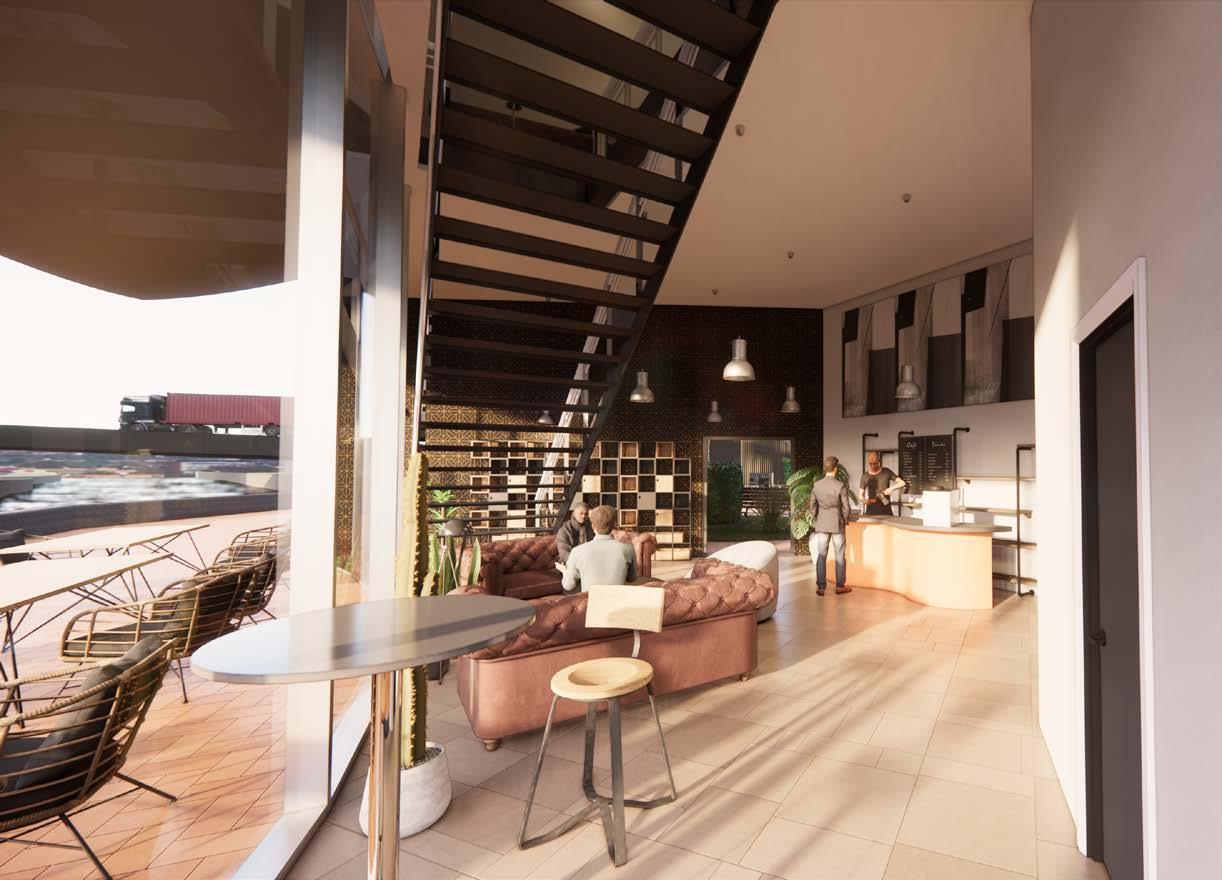
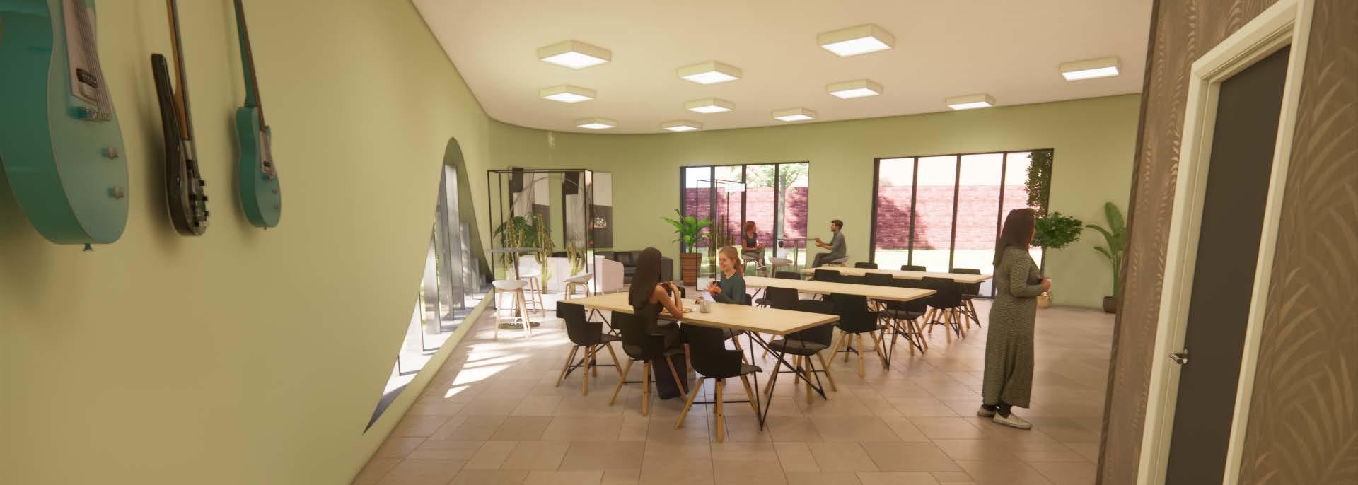
Cafe and Charity Shop
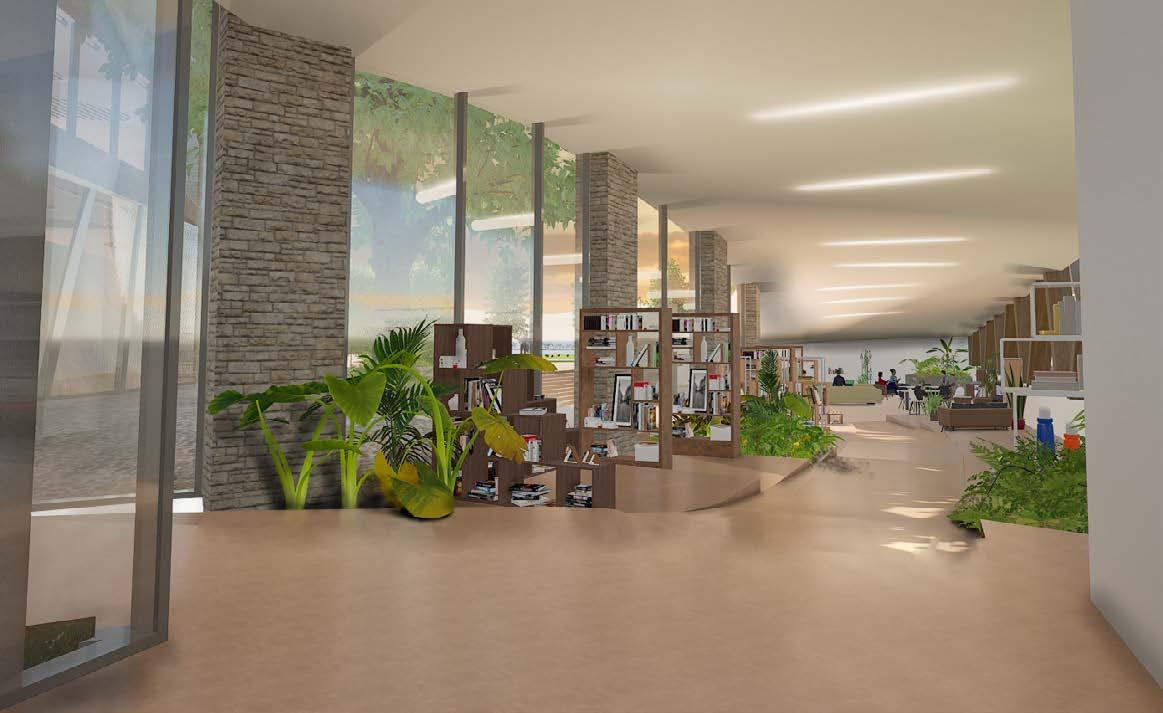
Charity Shop
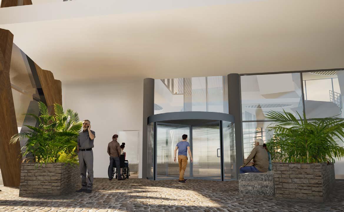
Main Entrance
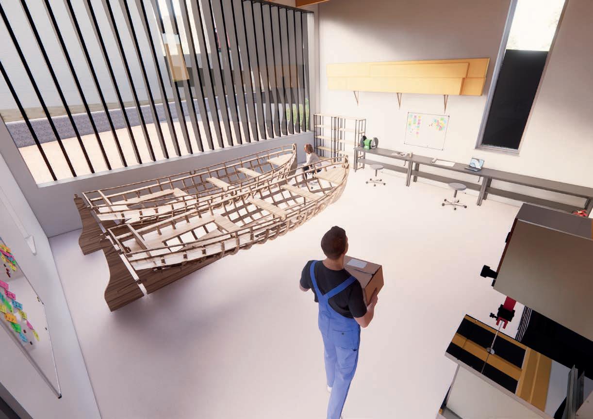
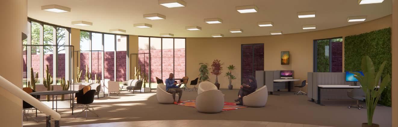
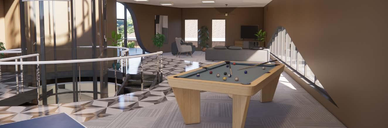
First Floor Workshop
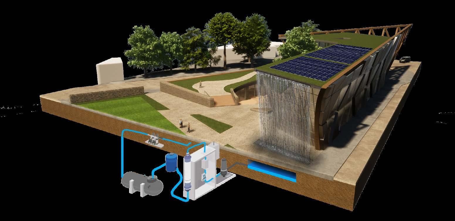
The building incorporates a grey-water system that recycles and purifies grey and rainwater back into usable water for flushing toilets and irrigation.
Solar thermal used to heat water for underfloor heating and hot water, water temperature is topped up using electricity if required.
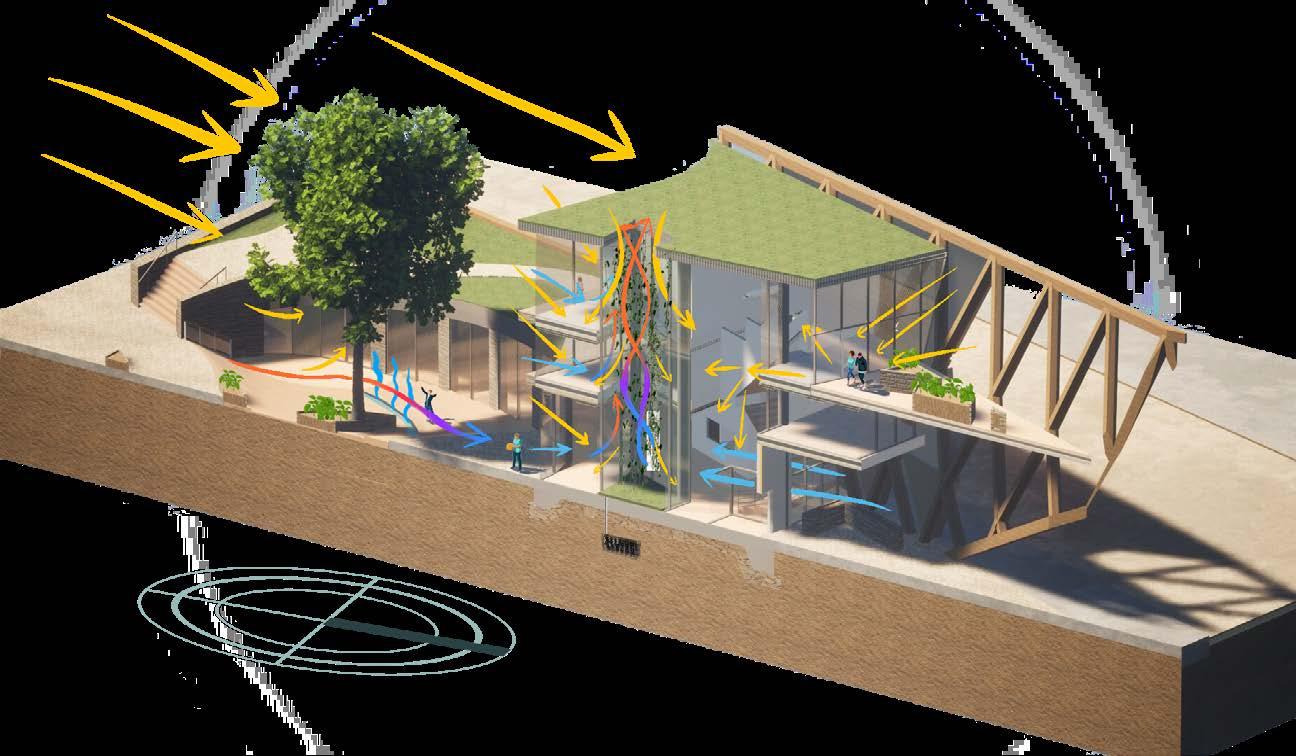
Water Management and Sustainability Passive Design
Solar panels used in conjunction with batteries to provide 24hr electricity in the building.
Rain water passes through water feature into the greywater tank where it is pumped through the system or back through the water feature.
ventilation through
Treated Water Tank
Grey-water Tank
Water Pump
Sodium Hypochlorite Dosing
Seasonal foliage of deciduous trees provides shading for the building from the south
Evaporative cooling from water feature provides cooling in the summer
Soak away for central green space.
Stack
the centre of the building can be used to cool the building.


Green Roof
Steel Centre Connection
Column Free Interior
Reverberation Reducing Ceiling
Insulated Steel Panel
Timber Structure Fixing
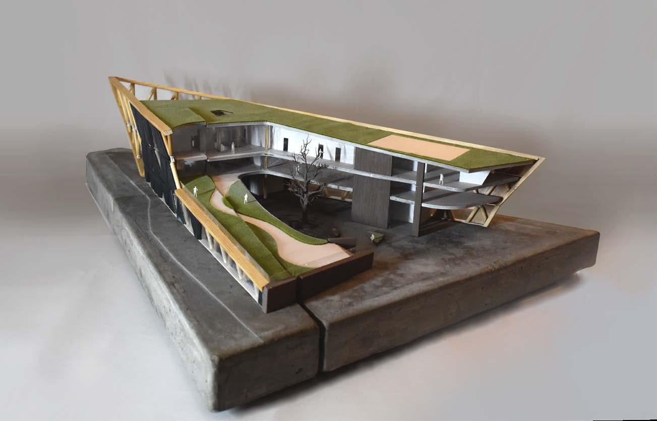
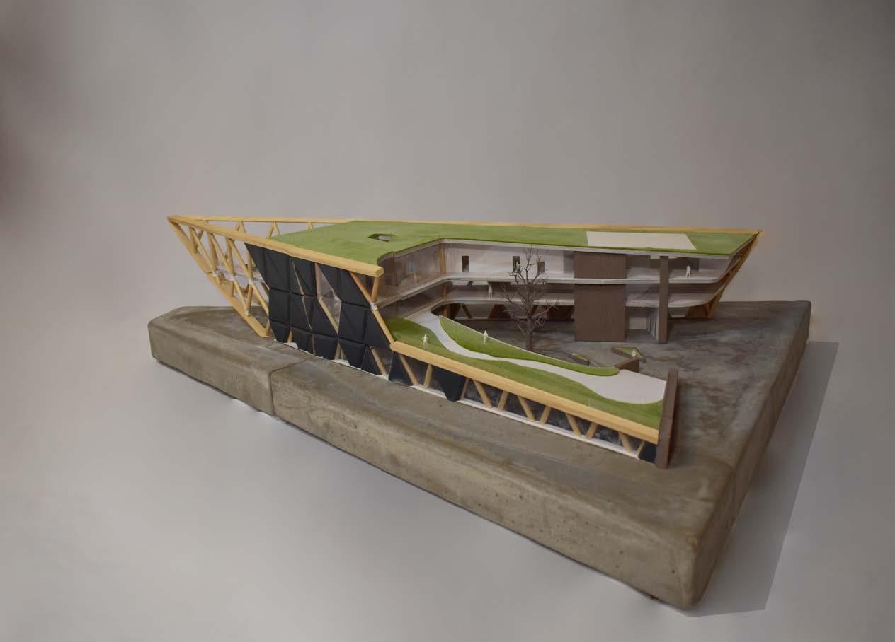
Section and Elevation
Planting
200mm Growing Medium
Filter Fleece
Drainage Element, Water Reservoir, Root Barrier Waterproof Membrane
2 Layers of 140mm Kingspan
Vapour Control Layer
Concrete Slab to Structural Engineers Calculations 200mm
Glulam Beam 300 x 150mm
Reverberation Reducing Suspended Ceiling
Rubber Sealing Component
Spider Fitting
Triple Glazing

kingspan Insulation
Mineral Wool Insulation
Plywood Internal Finish
Vapour Control Membrane
Timber Support
Low Density Fibreboard
3mm Steel

Construction
Systems
Used in the Building
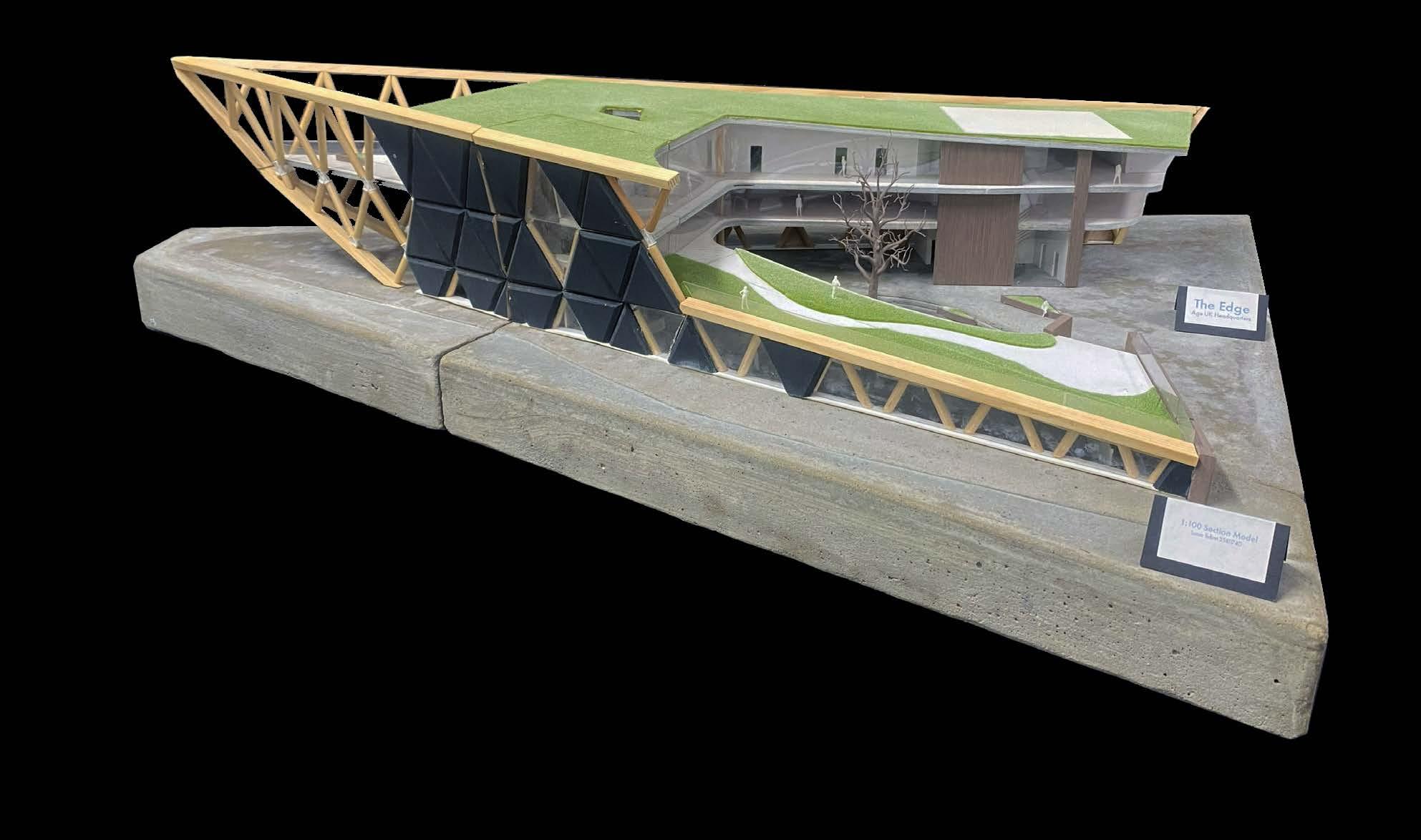
Some of the construction systems that will be used within the building are green roofs; two types of green roofs will be implemented within the building: an extensive system that will be inaccessible to the public, and a semi-intensive roof that will provide access to the first floor from the south of the site.
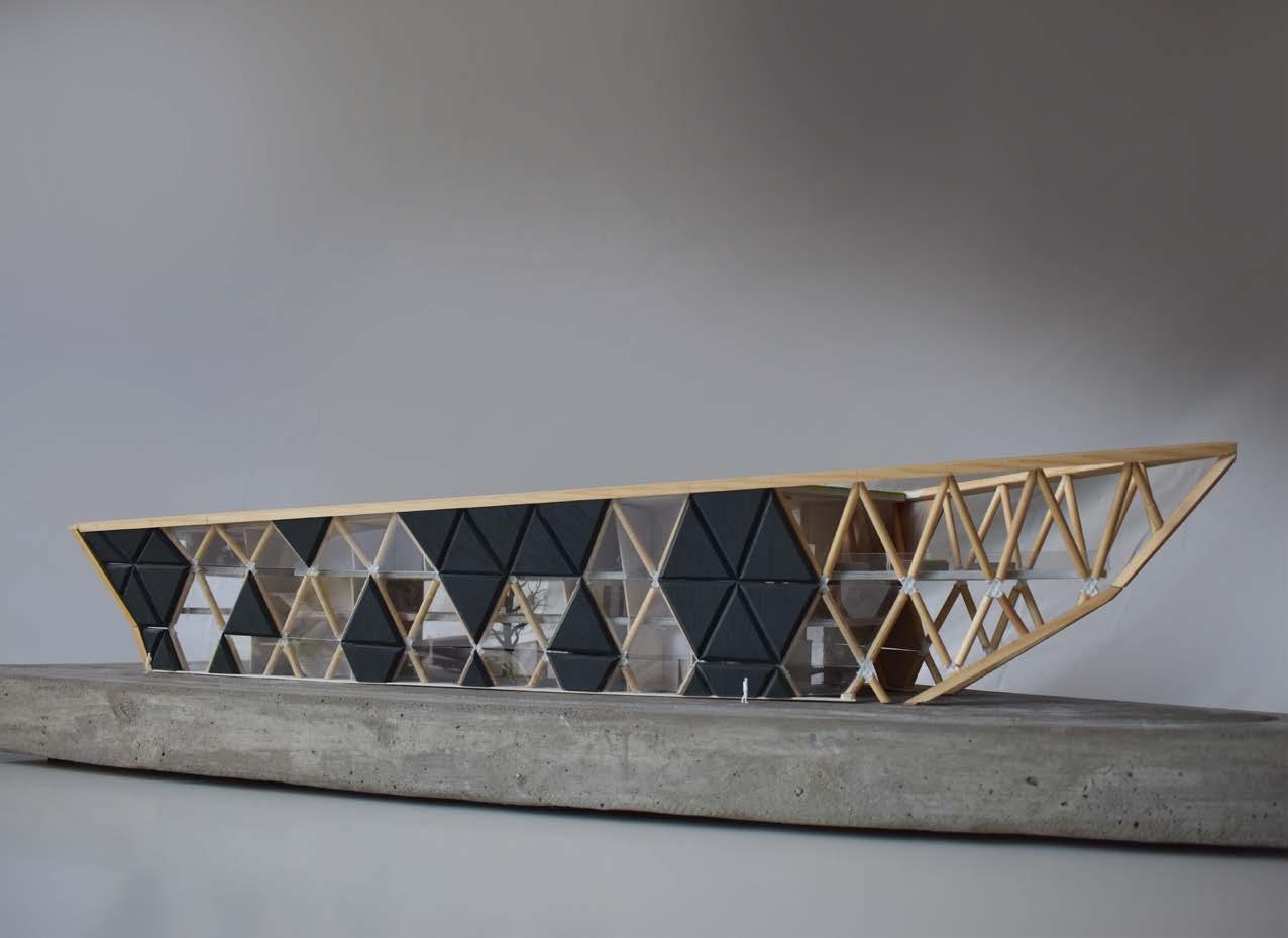
The building will also incorporate a glass façade system that will connect onto the wooden structure, via a steel spider connection which will allow the structure to be visible from the exterior of the building whilst still maintaining an air-tight building membrane. This airtight membrane will reduce heating and cooling costs, mechanical and natural ventilation can be used to cool the building and solar gain can be used to help heat the building in winter.
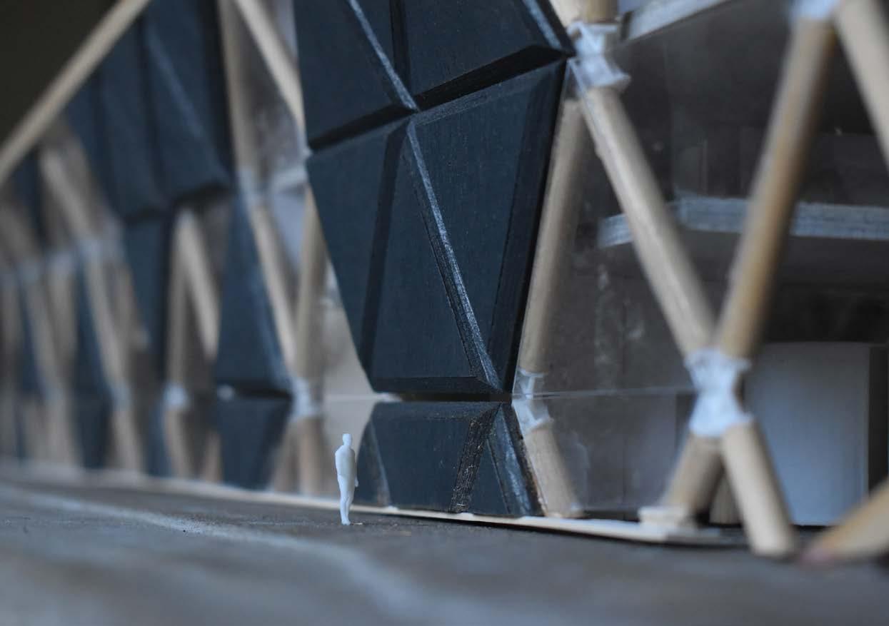
The façade will also incorporate sections clad with insulated steel panels which will maintain the shape of the structure using bevelled edges.
Section of Spider Fitting 1:10
Section of Insulated Steel Panel and Connection, 1:20
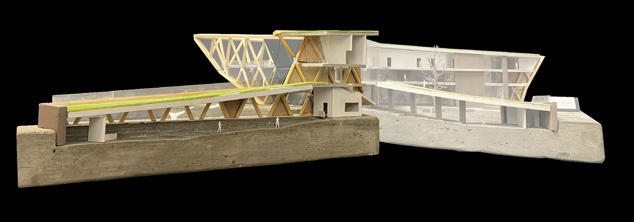
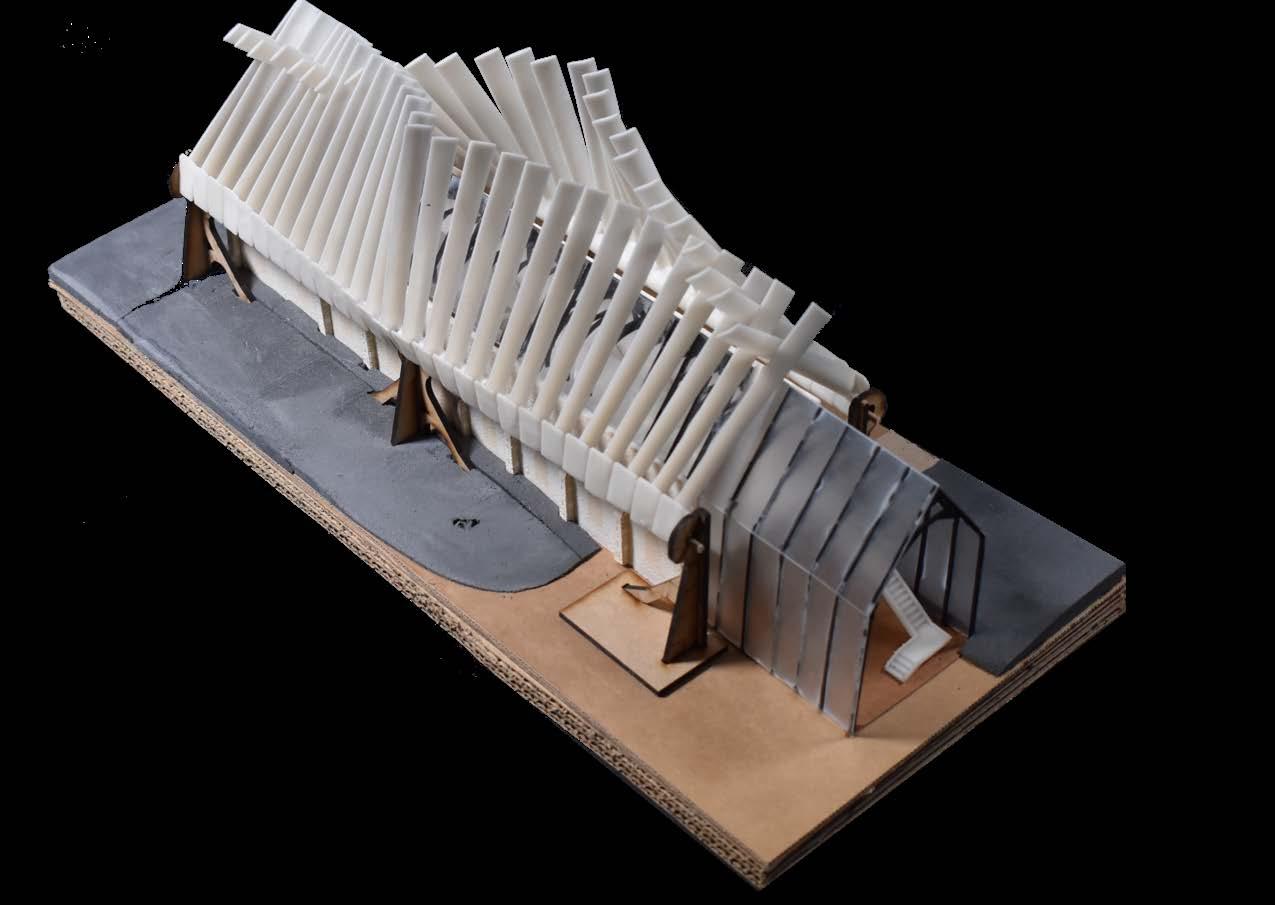
This model was made using a variety of processes. First a mould was made for the concrete to be poured into, which contained reinforcing rods and also the raised profile to produce the stairs and lower ground floor. The Intermediate floors and roof were laser cut and spray painted, and the triangular panels were laser cut and then sanded to create the bevelled edge, then painted. The dowel representing the diagrid system was chopped to length and then sanded and assembled with 3D printed centre pieces, all the interior walls were made from mount board and cut by hand.
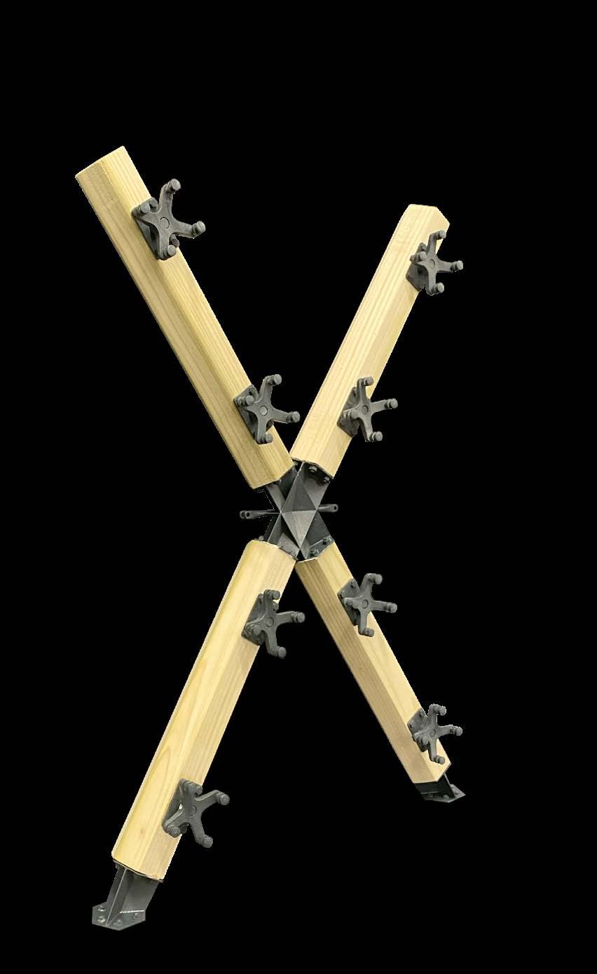
1:10 Scale Model of Diagrid Structural System
1:100 Scale Section Model of Full Building
Created from 3D printed parts designed on Autodesk inventor, wood sawn and sanded into a hexagonal profile.
Physical Models
Physical Models
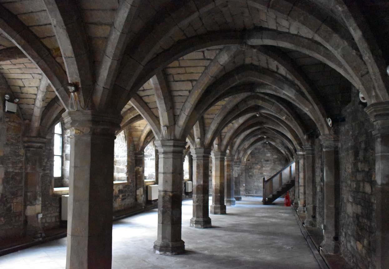
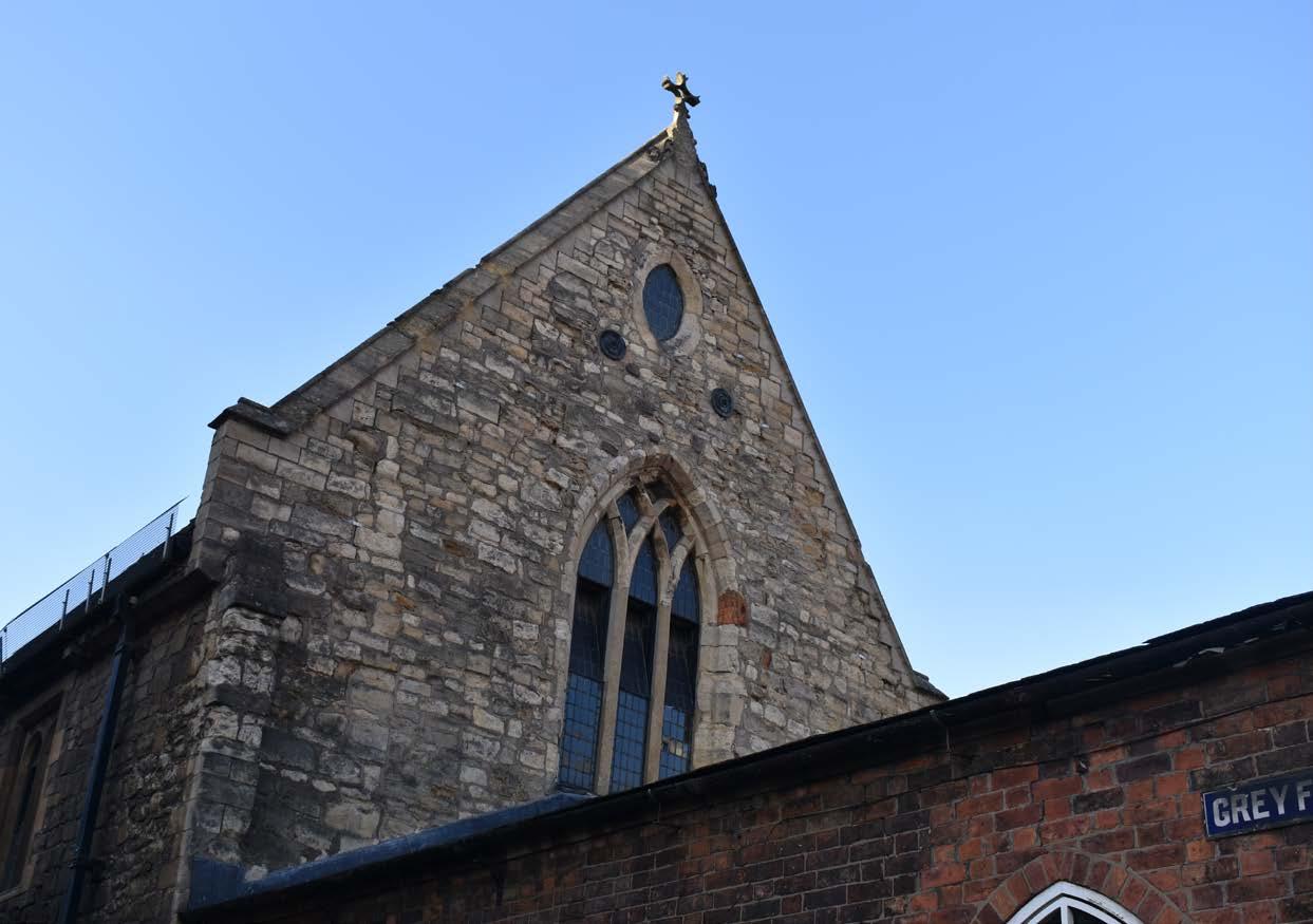
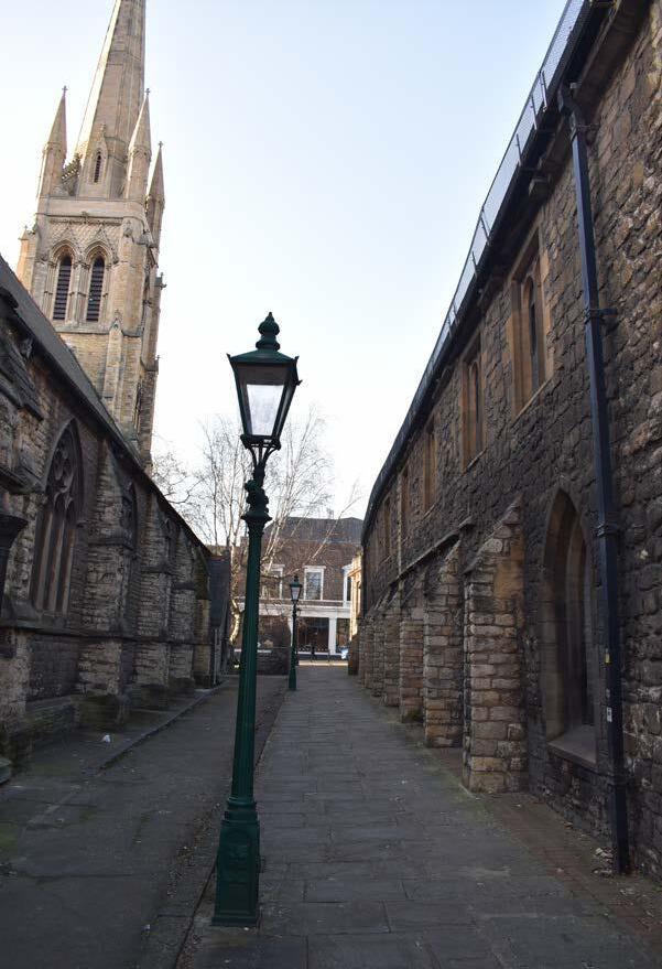
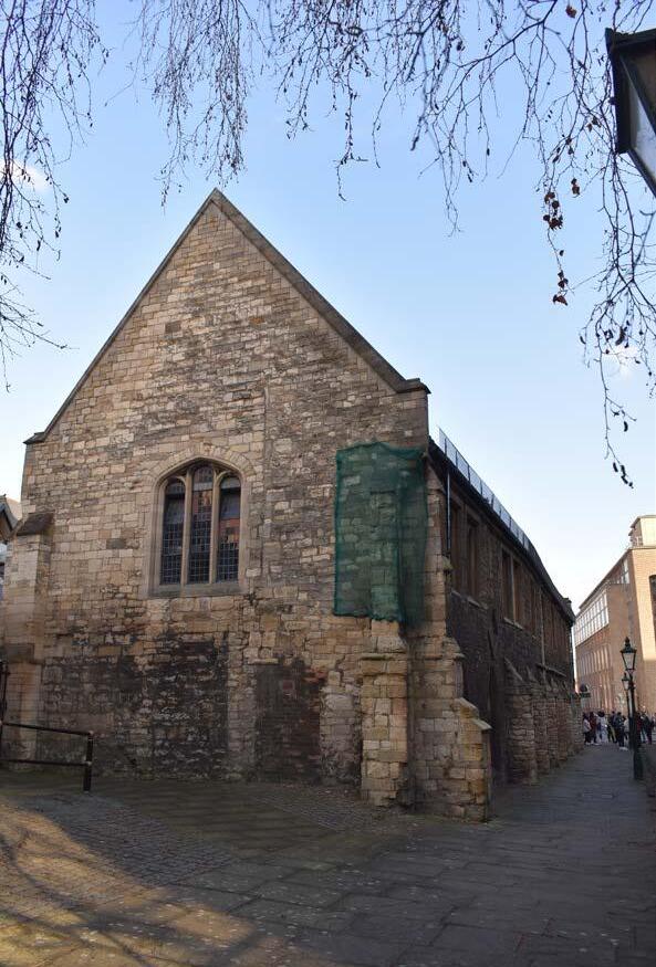
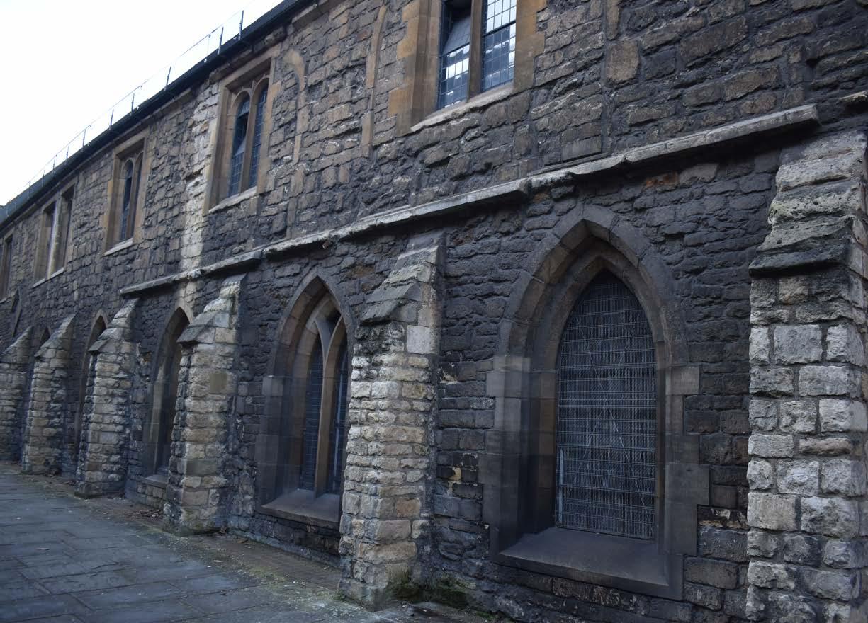
Project B - Greyfriars Redevelopment
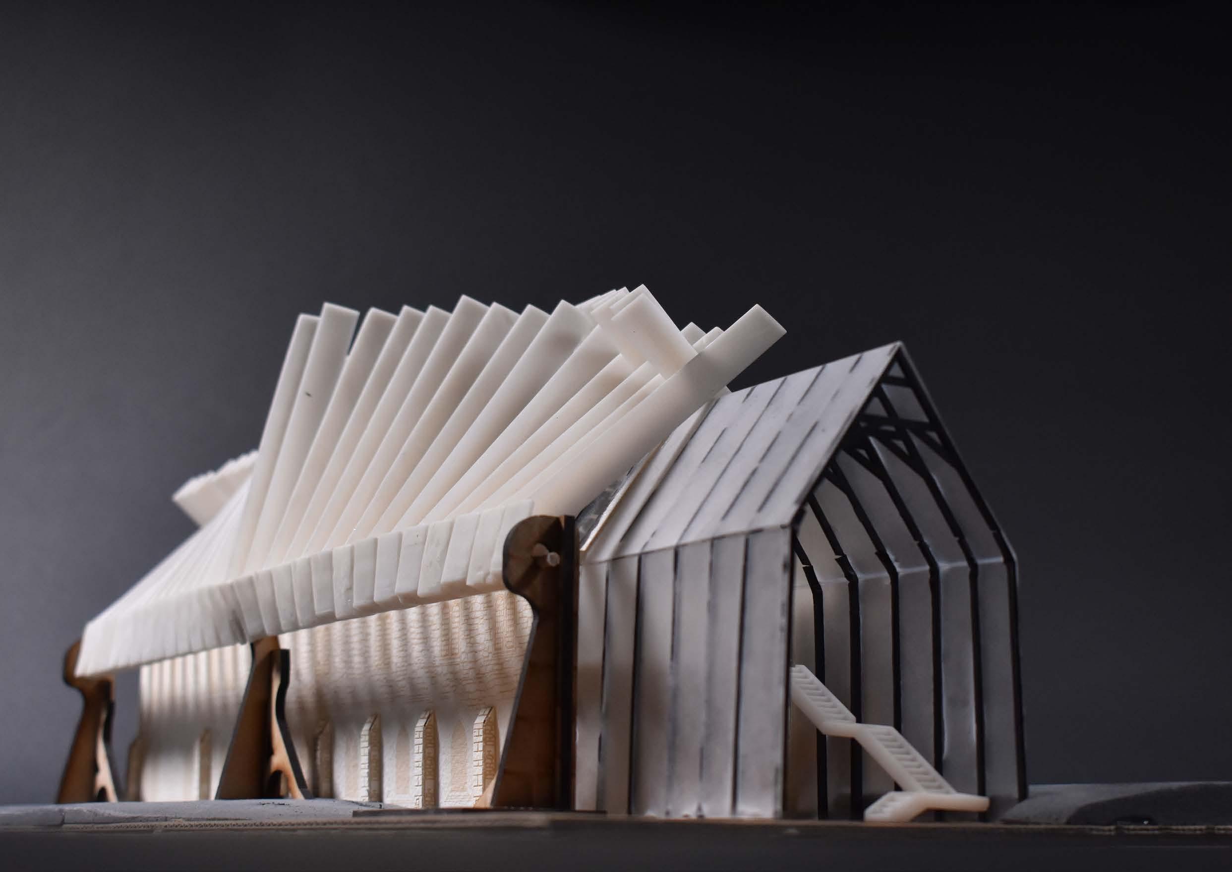
This Brief for this project was to re-purpose an existing building in Lincoln called the Greyfriars into a visitor centre with the theme of a historic event in Lincoln. The historical event I chose to work with was the Turbojet Engine, developed by Sir Frank Whittle while a cadet at RAF Cranwell.
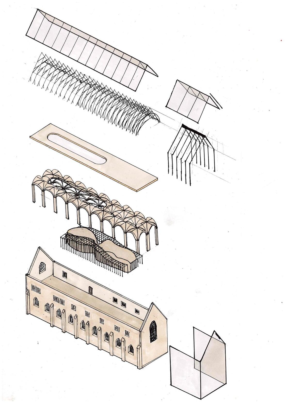
The response to the project involved adapting the roof to glass to allow light into the first floor of the building where there would be a cafe and an exploded gas turbine, as well as information and other models about the evolution of the gas turbine. Above the glass roof a shading structure would be able to move made from scaled up gas turbine blades which could be seen throughout the building. The ground floor would house an interactive gas turbine experience which would help people understand how they work, utilising the human senses to represent air passing through the gas turbine.
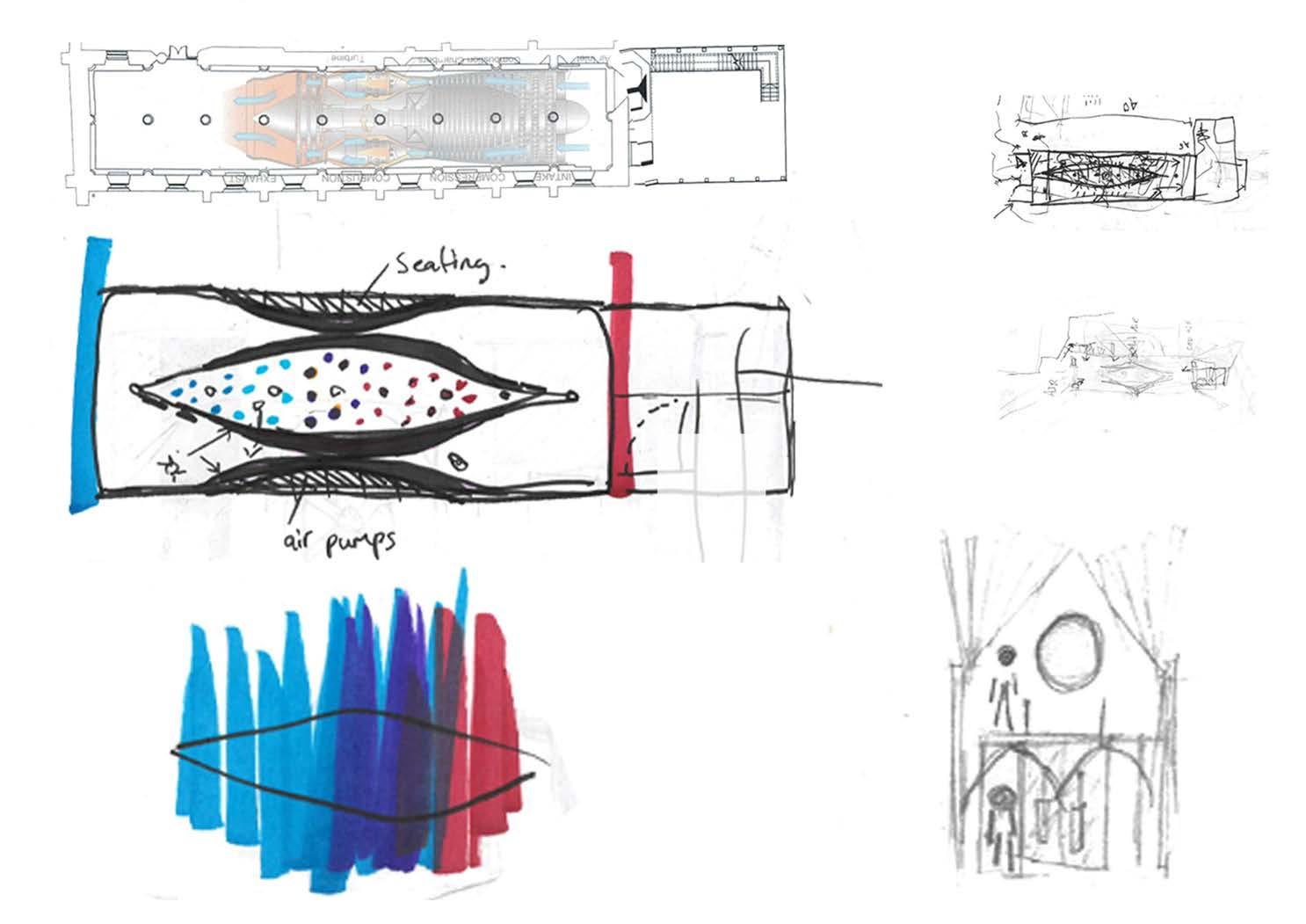
Concept Development

On the top floor a cafe will be situated with information posters and displays and a centrepiece exploded gas turbine, suspended over a void in the floor so that it can be viewed by people both up and downstairs.
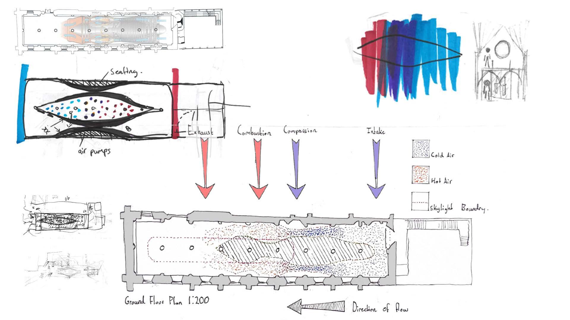
Development of the ground floor showing areas of hot and cold and also the areas of contraction and release. As well as showing the skylight and the open space underneath which can be used to pause and view the exploded gas turbine and roof structure from below, connecting the upper and lower spaces.
The concept for the ground floor is to make people experience what a gas turbine does.
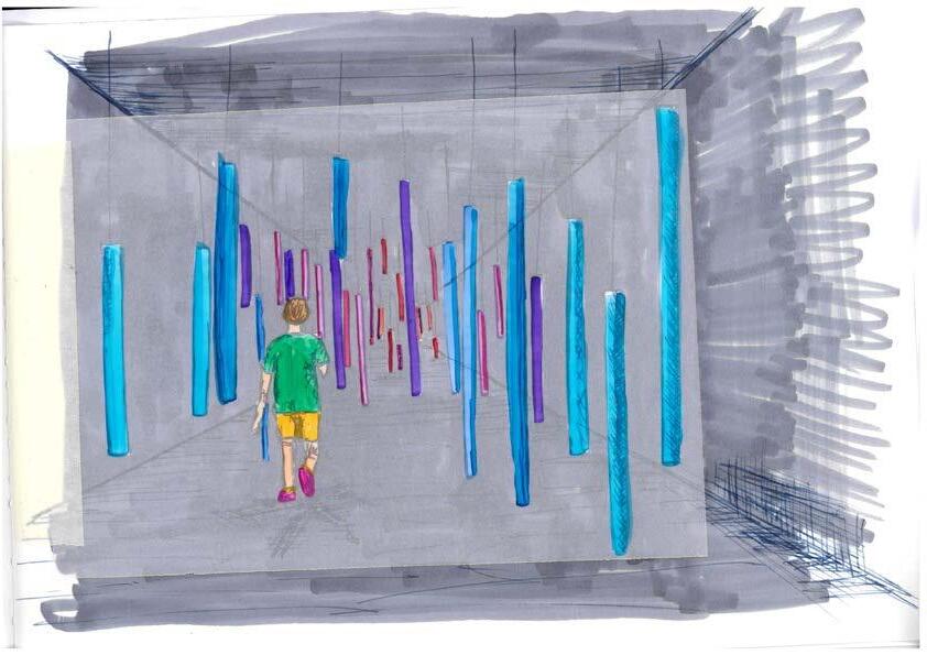
The idea is to make people feel as though they are the molecules of air flowing through a turbine through hot/cold air and compression and expansion of spaces. A light display with fluorescent tubes, changing from red to blue in the centre, is another interactive experience.
The model was made from a combination of processes, the turbine blade shading on the roof and the barrel vaulted ceiling were designed on Autodesk inventor and 3D printed.
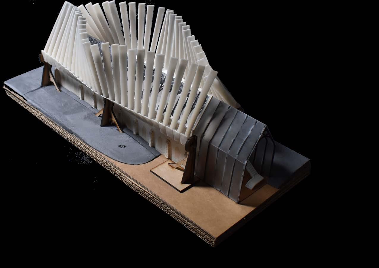
The supports for the blades were drawn on Autocad and laser cut along with the trusses and walls of the building.
The turbine blade shading can be seen open at different angles in the two above images.
Arches varying in size to create feelings of compression and release, whilst changing in colour to match the change in temperature through heat lamps and cold air blowers. Disabled friendly toilets.
Disabled friendly toilets.
Arches varying in size to create feelings of compression and release, whilst changing in colour to match the change in temperature through heat lamps and hot and cold air blowers.
Outdoor storage.
Outdoor storage
Stairs descending down to ground floor lobby from extension.
Stairs descending down to ground floor area from extension.
A light display accessible through curtains to keep it dark inside, with a skylight at one end looking up to the above gas turbine.
A light display accessible through curtains to keep it dark inside, with a skylight at one end looking up to the above exploded gas turbine.
Main entrance.
A large turbine blade embedded into the floor under glass, illuminated with leds.
A large turbine blade embedded into the floor under the glass, illuminated with LEDs.
Main entrance.
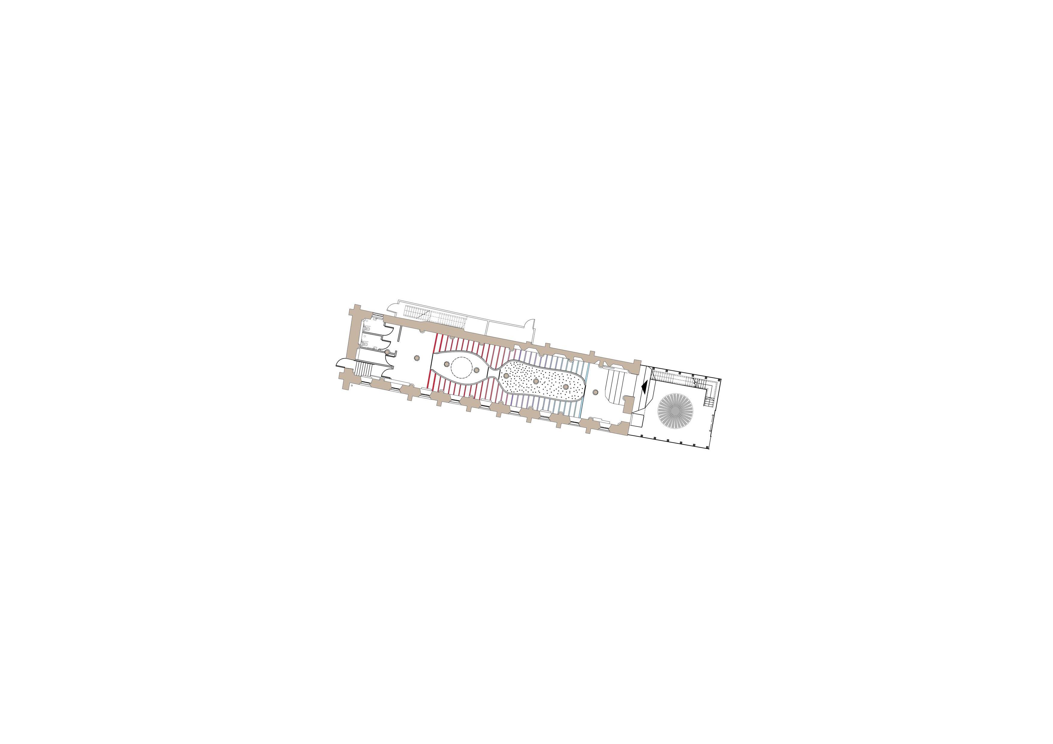
First Floor Plan 1:200
Dotted line showing the elevated exploded gas turbine.
Cafe area with tables and chairs
Storage cupboard for cafe.
Display boards surrounding the upstairs walls
Dotted line showing the elevated exploded gas turbine.
Storage cupboard for cafe.
Display boards surrounding the upstairs walls.
Cafe area with tables and chairs.
Section Showing the downstairs and upstairs displays as well as access to the upper floor.
Section showing the downstairs and upstairs displays and cafe, as well as access to the first floor .
Extension - housing the emergency staircase and storage areas, constructed from reclaimed stone from other areas of the
A
in
to
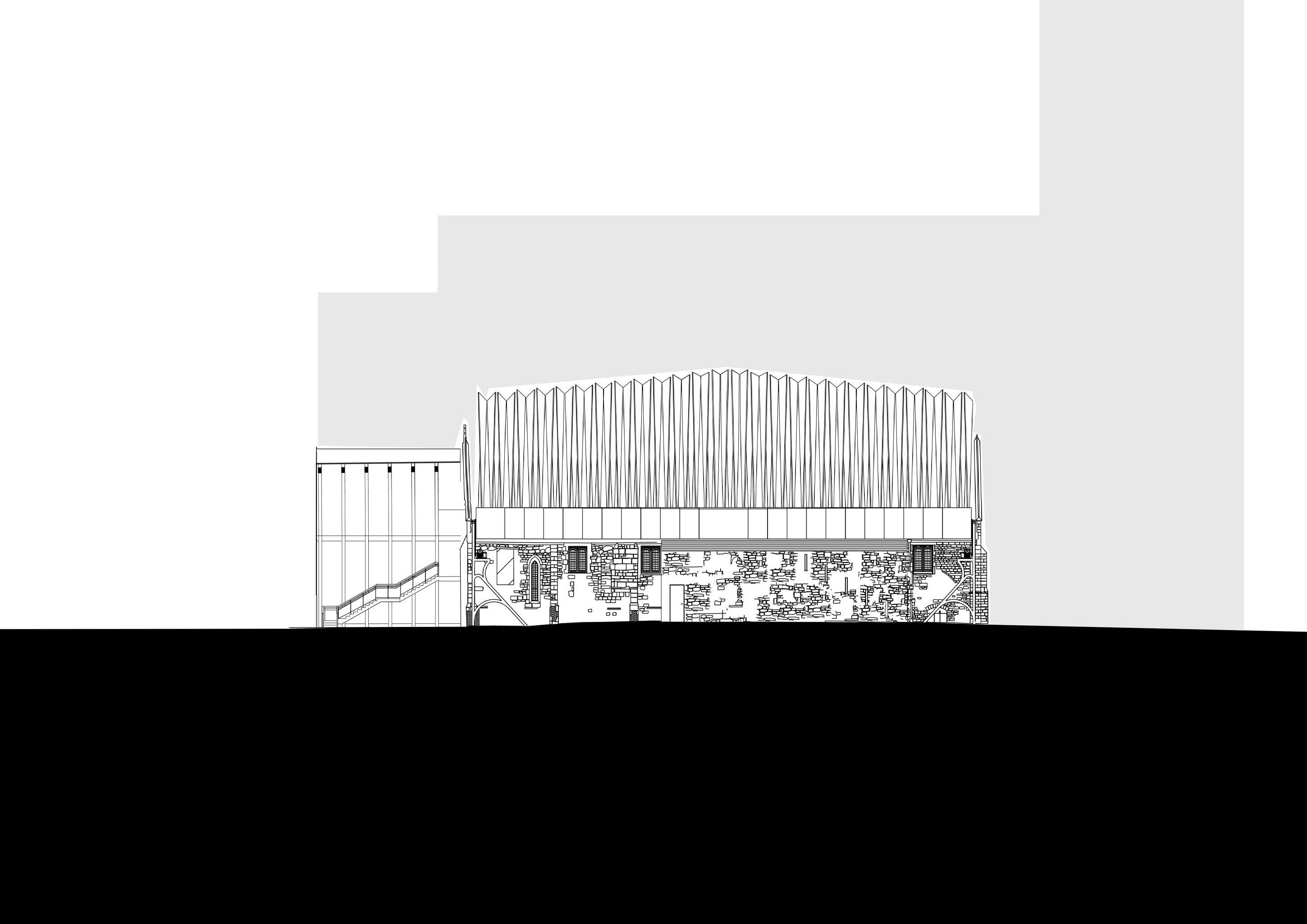
Extension housing the emergency staircase and storage areas using removed stone from other areas of the building and locally sourced limestone, shallow angled pitched roof and slotted windows similar in shape to that of the very first greyfriars before the use of large glass panes.
and
and
building
locally sourced limestone.
shallow pitched roof
slotted windows similar
shape
that of the original Greyfriars before the use of large glass panes.
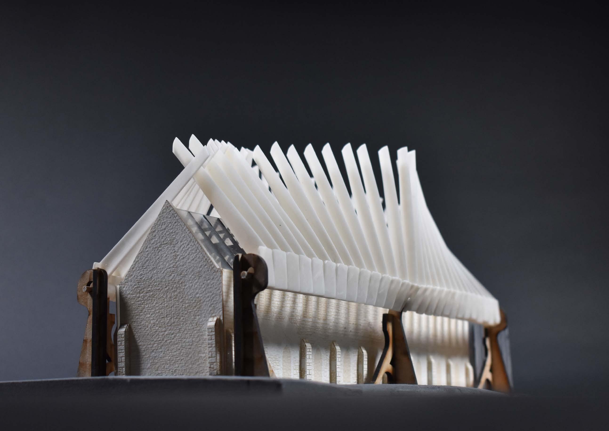
Model Photo
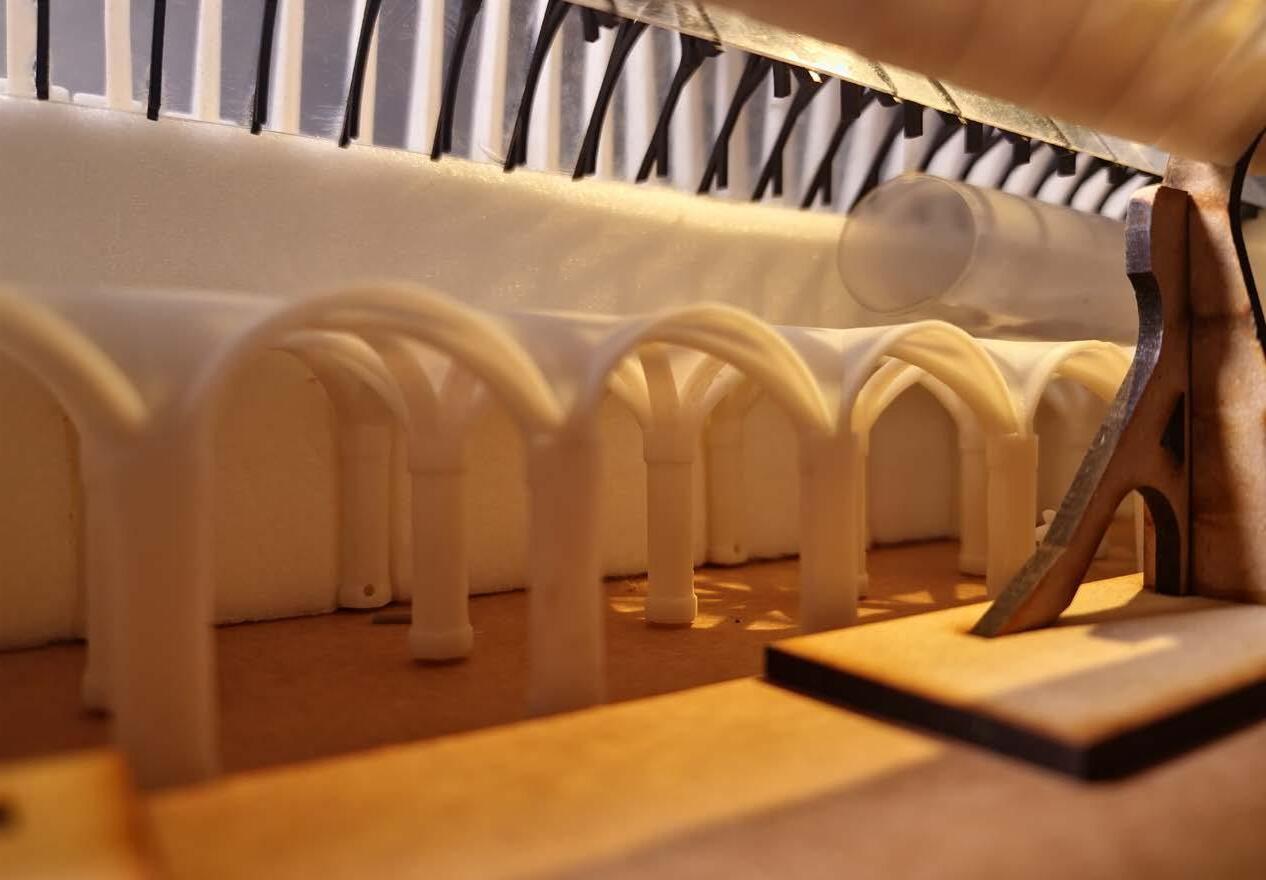
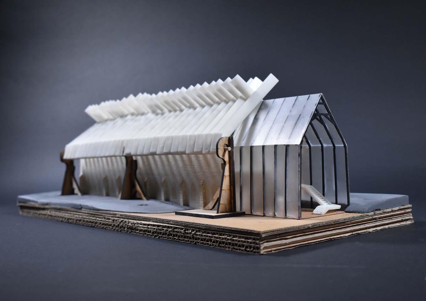
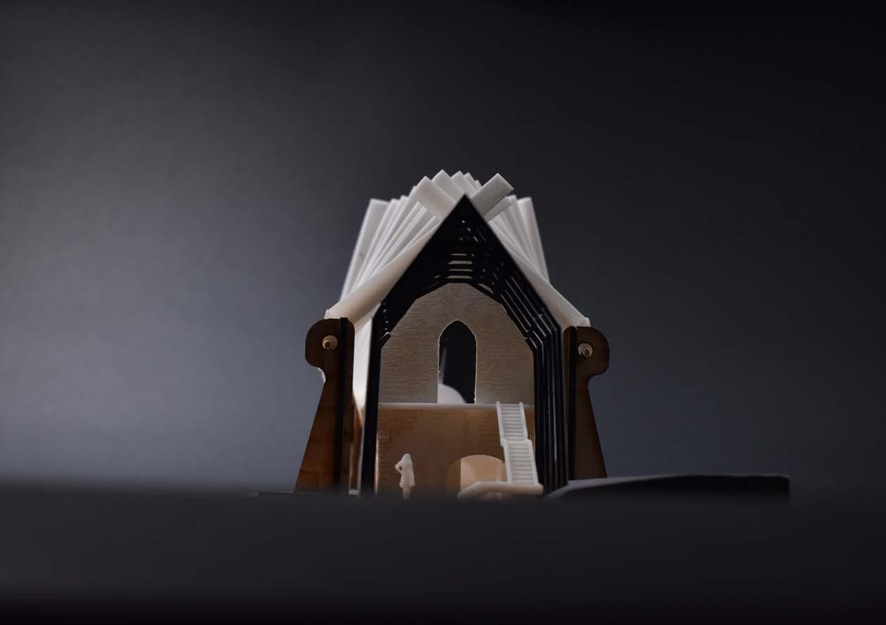
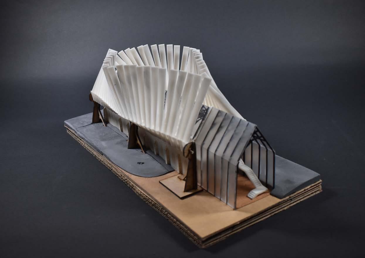
Model Photos
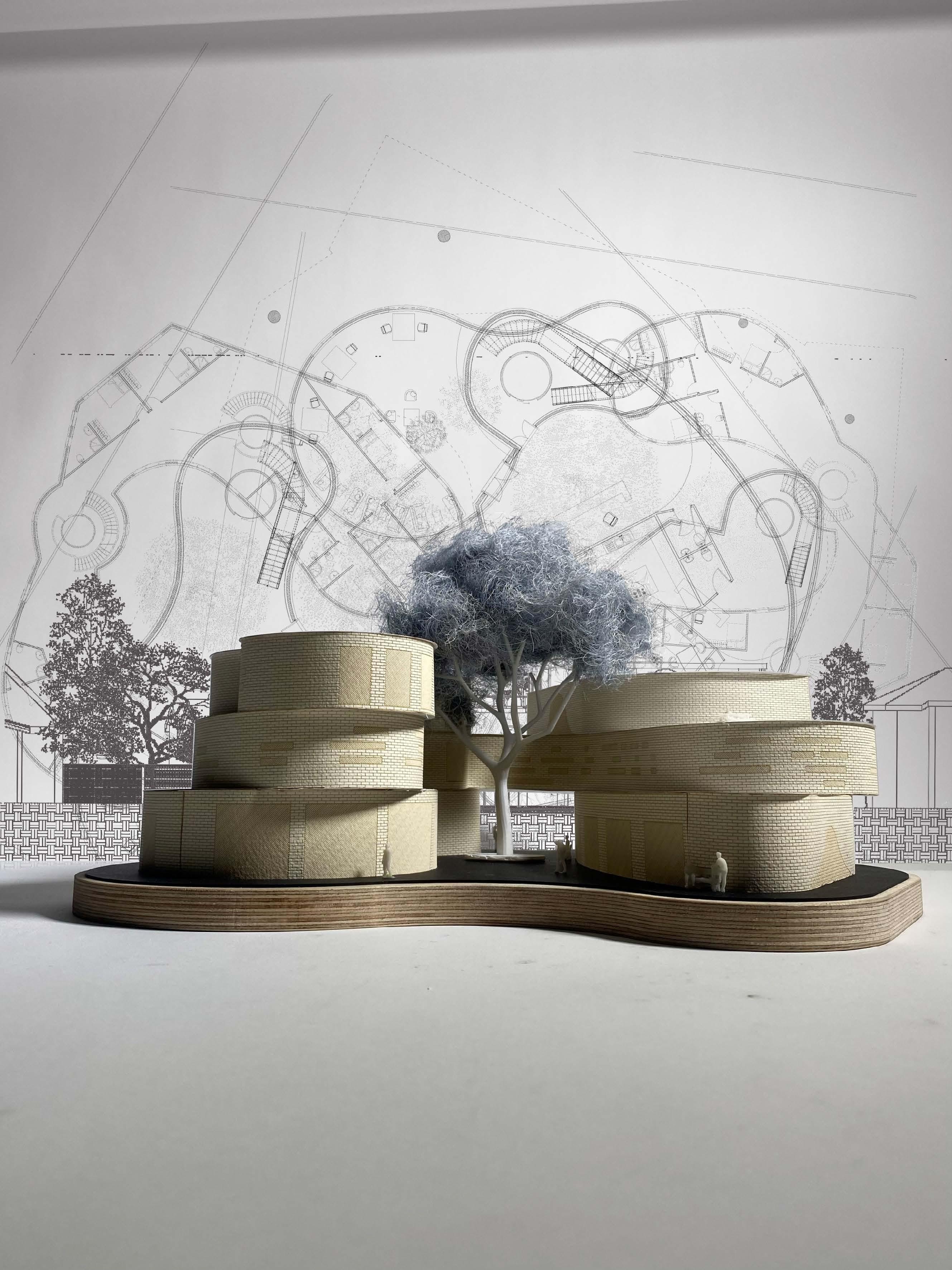
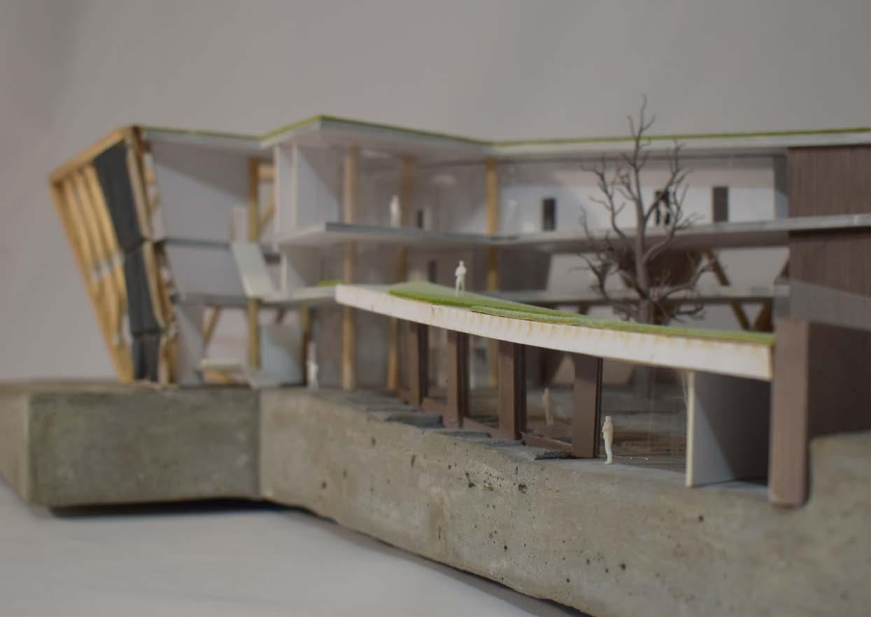
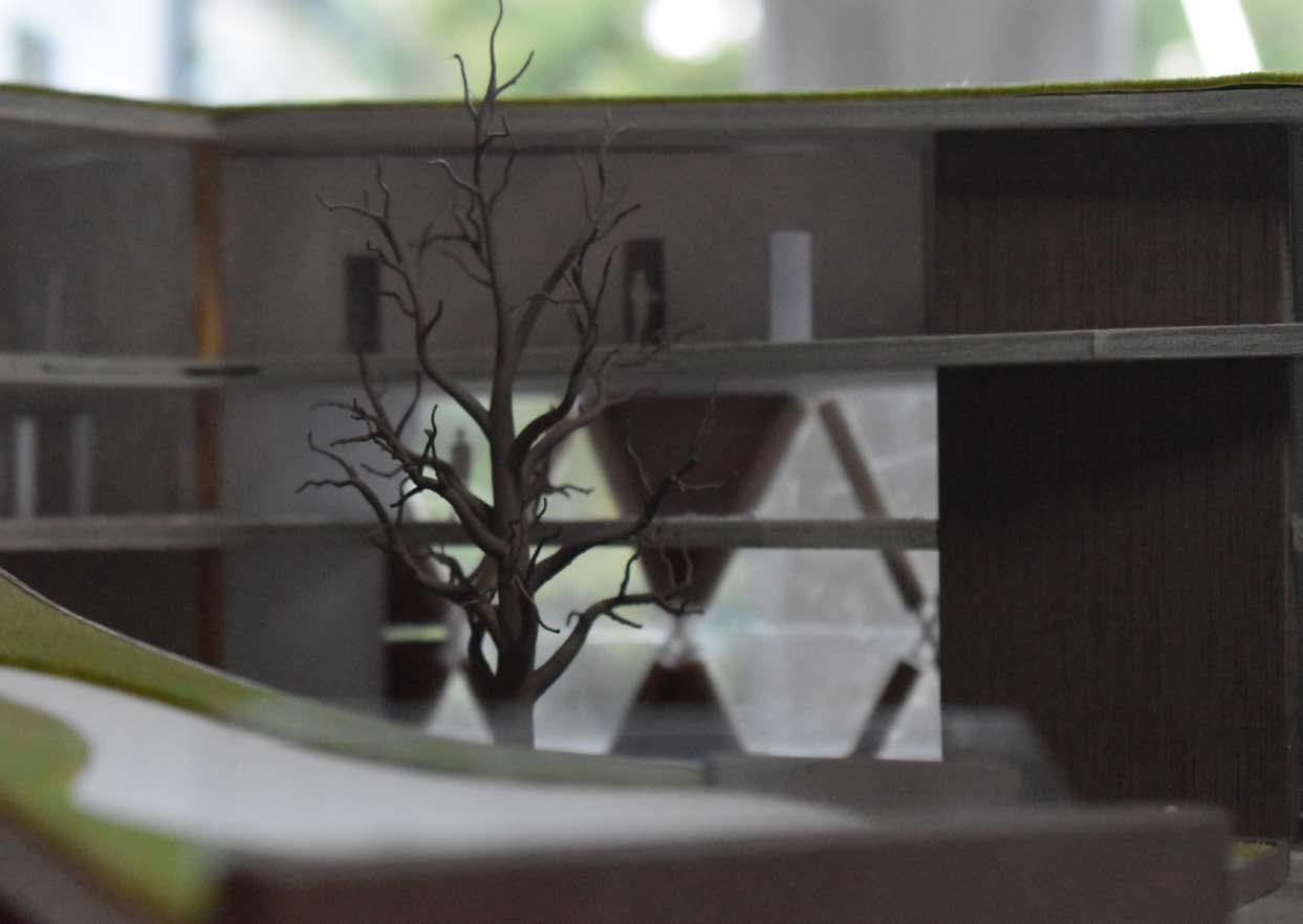
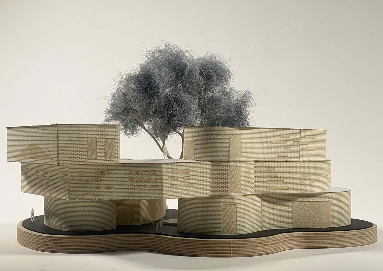
Project C - Horseshoe House
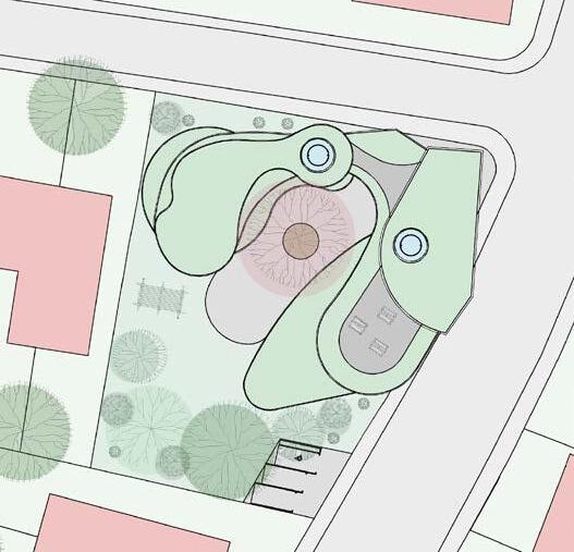
The brief for this project outlined a building that both young and elderly could be co-housed. The building responds architecturally to this by having social spaces for both parties and also having separated accommodation to help with differing sleep schedules and lifestyles.
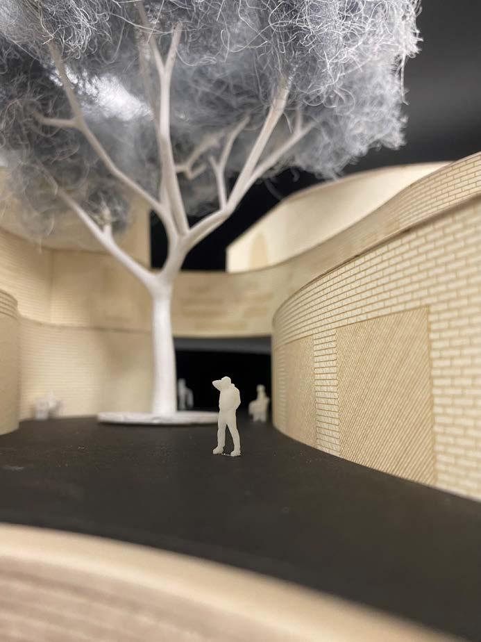
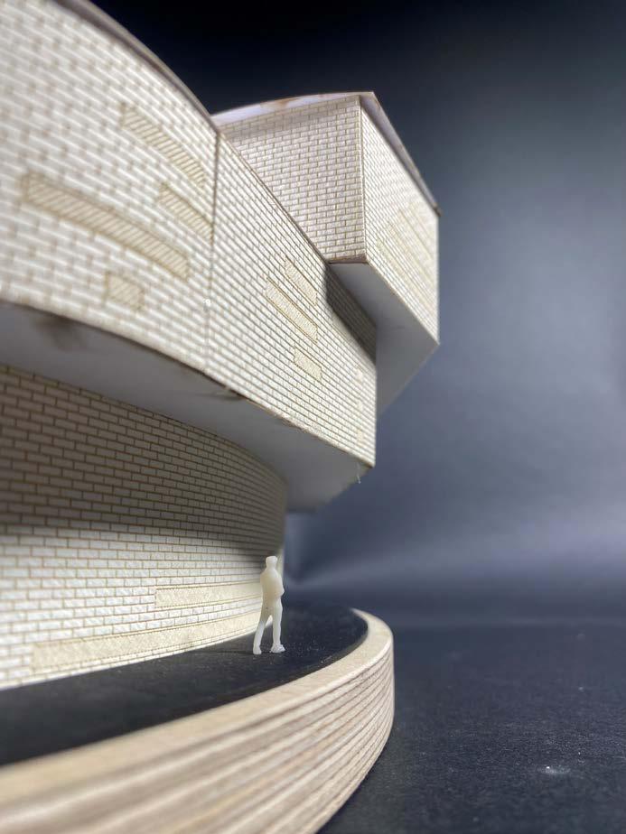
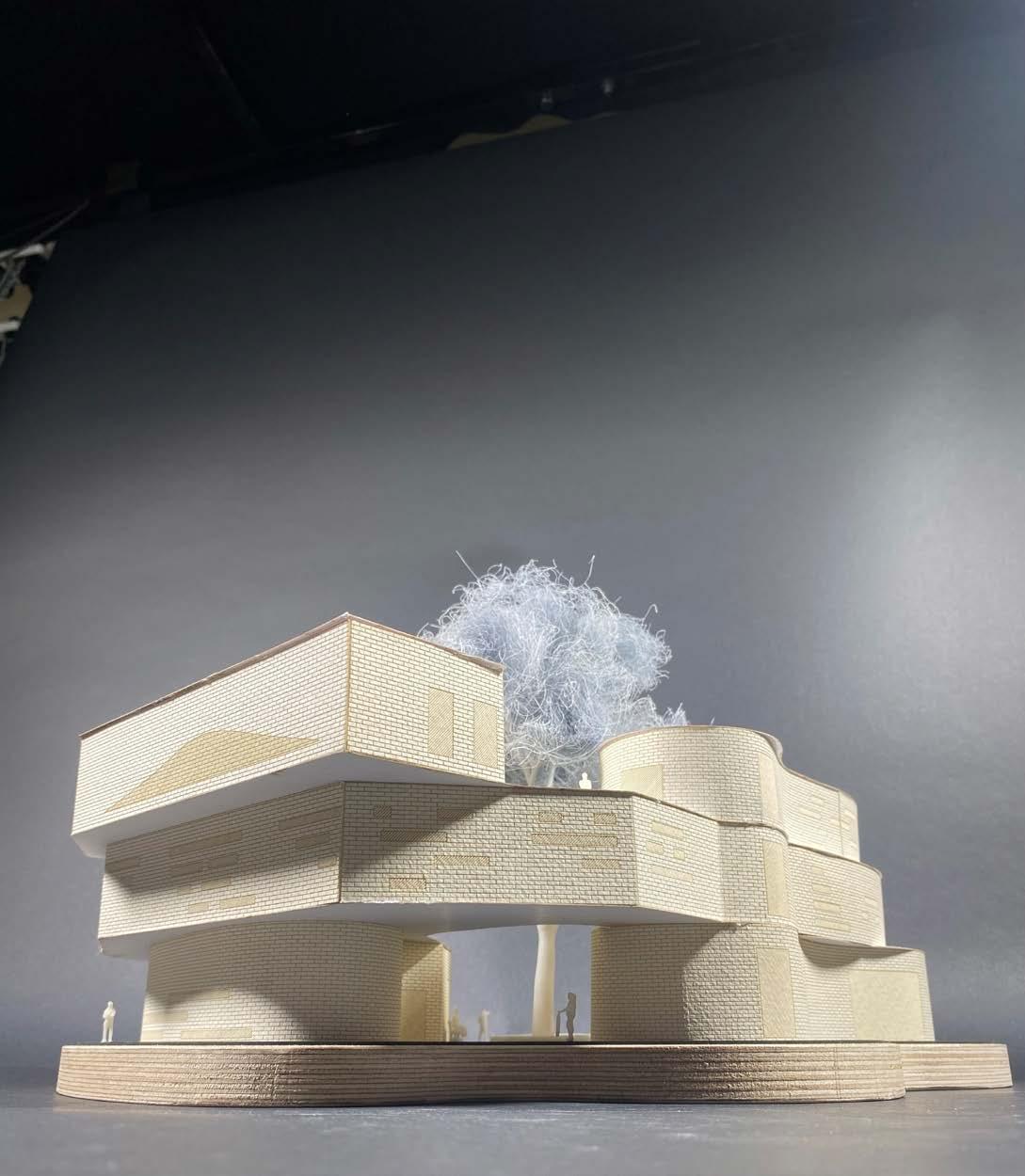
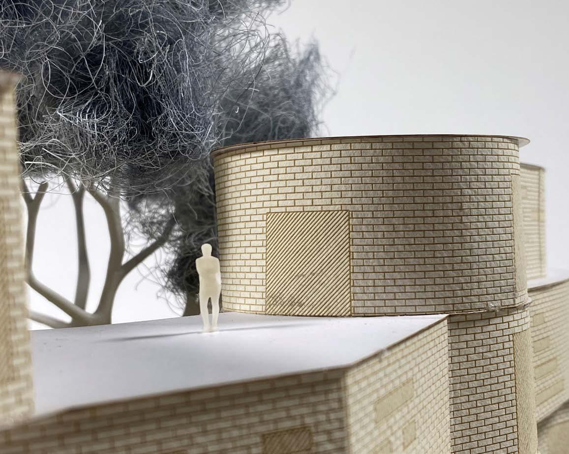
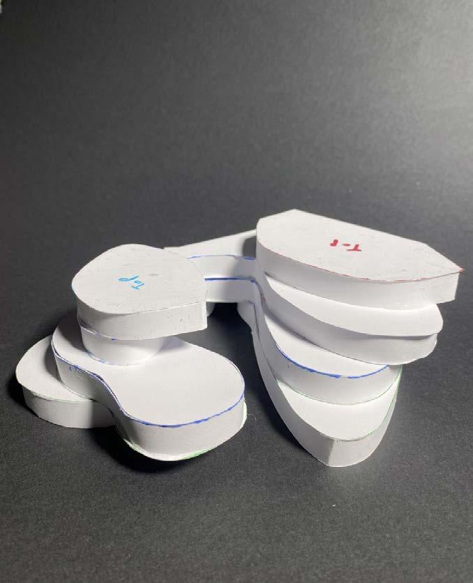
Models were used to progress this design and play with forms, helping to see how the building interacted with the site and its surroundings. The final model, pictured in the bottom left, was created from a Revit model by unfolding the walls on a software called Pepakura, cleaned up in Autocad and then laser cut. The base was CNC routed and the tree and people were 3D resin printed, with the foliage being made from steel wool.
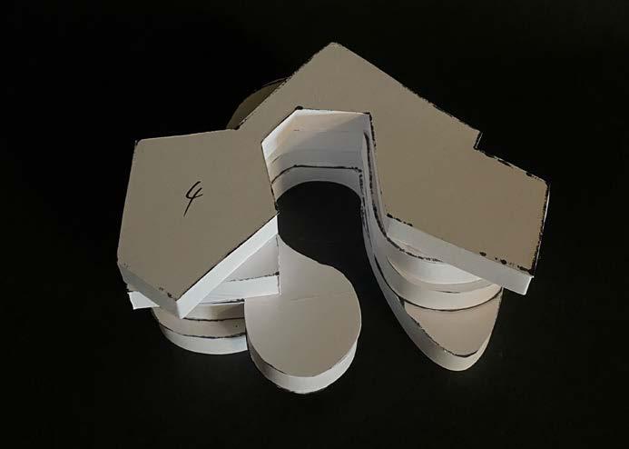
Physical Models
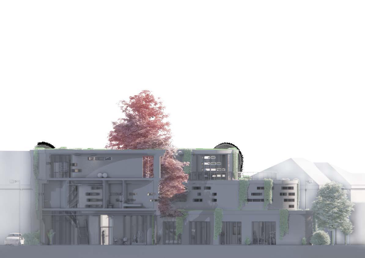
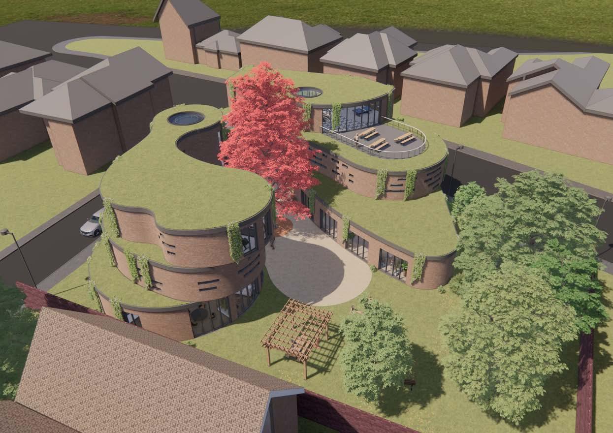
Exterior Visualisations
Project D - Brayford Hub
The brief for this project required a boat building workshop, together with a cafe and other workshop spaces for people to learn about crafts.
The response to the brief was to split the site into several buildings retaining the walkways which are used frequently. The buildings also incorporate a wave style facade representing the water, which is closely linked to the site.
Section Map