commentary serves as a tool of personal reflection to give further context to the work.
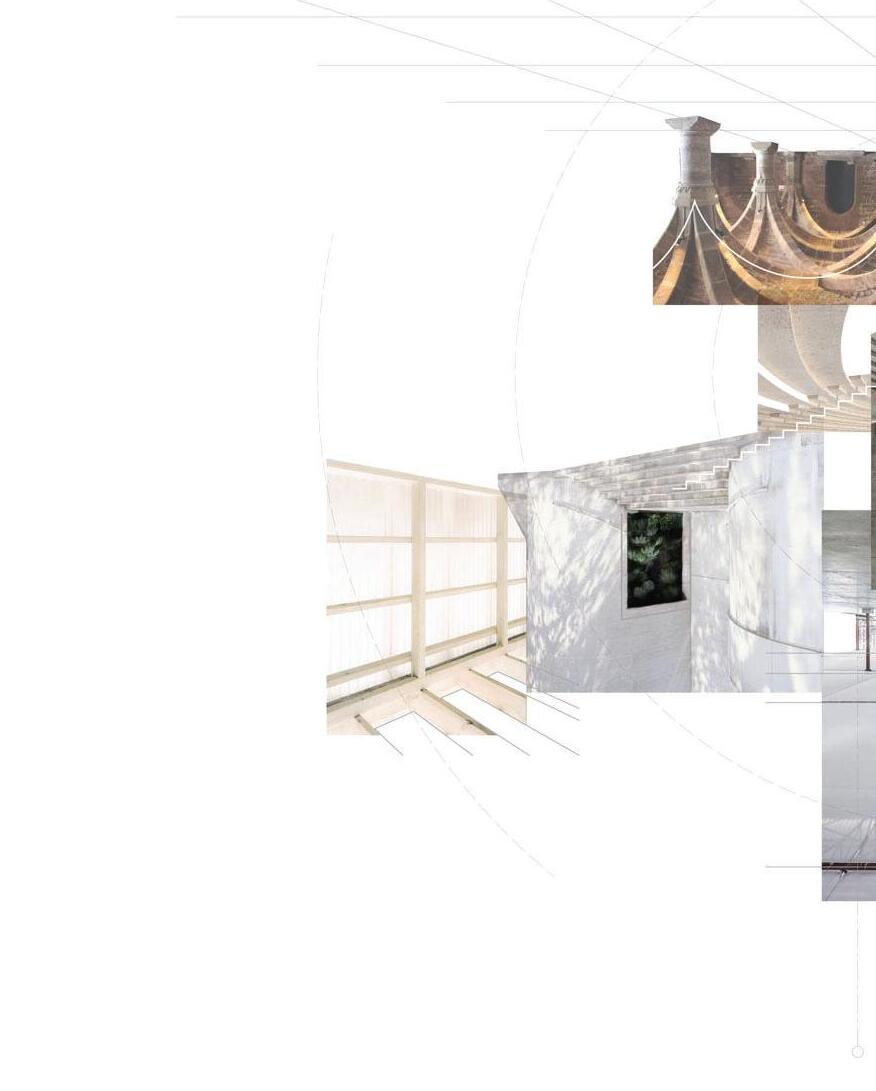
PORTFOLIO Luke Blair Work from 2017 - 2023 CONTENTS 01 Cover 02 I.C.H. 07 Comprehensive Design 11 Circular Construction 16 Phenomenology 19 Assembly 23 Strap Table 24 Appendix A 25 Appendix B with commentary!
1
My first semester in graduate school at Rice University, I was fresh to Houston and its brutal summer humidity.
I.C.H.
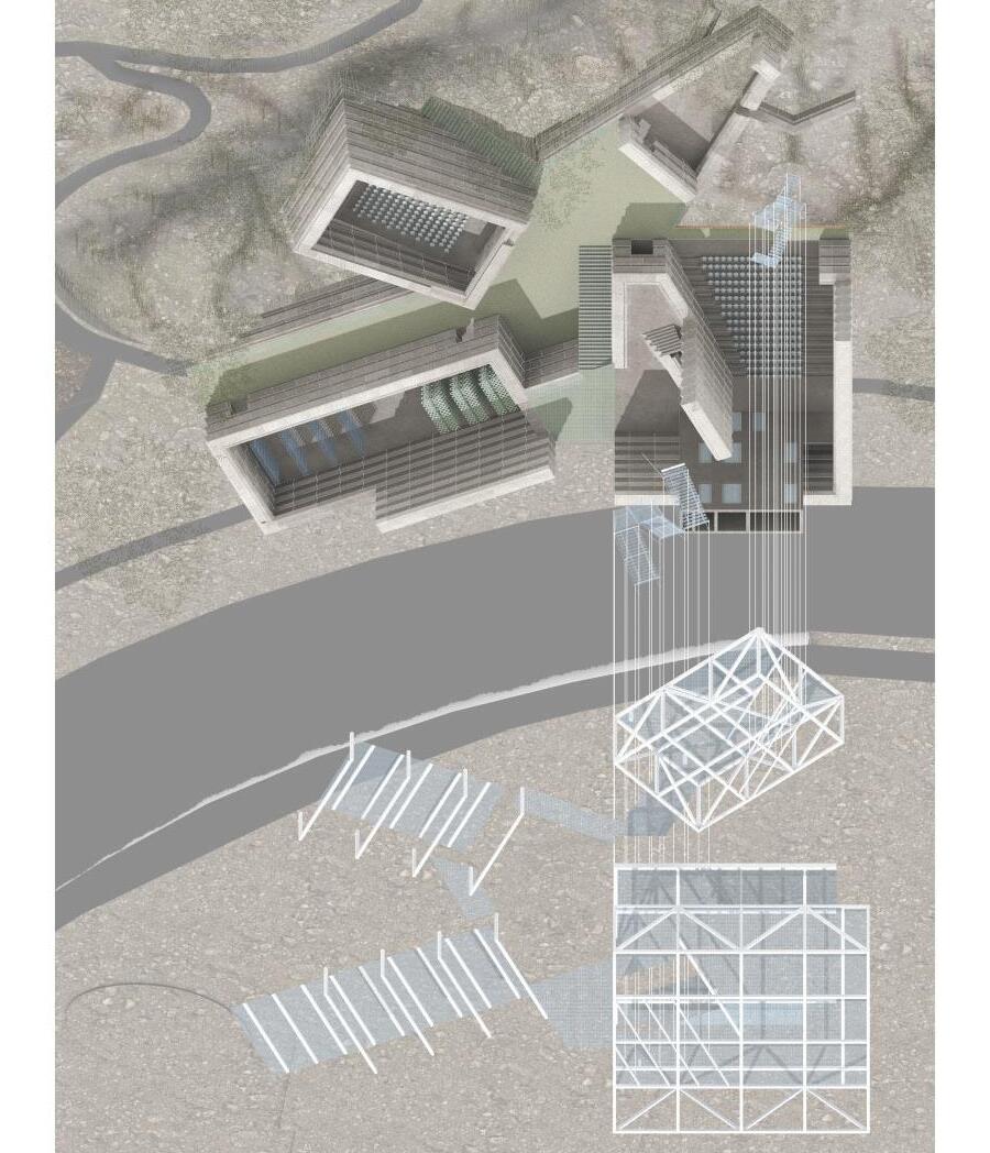
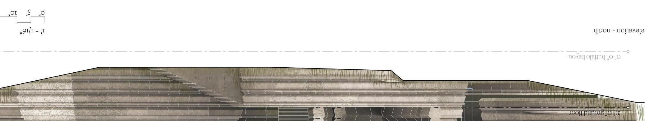
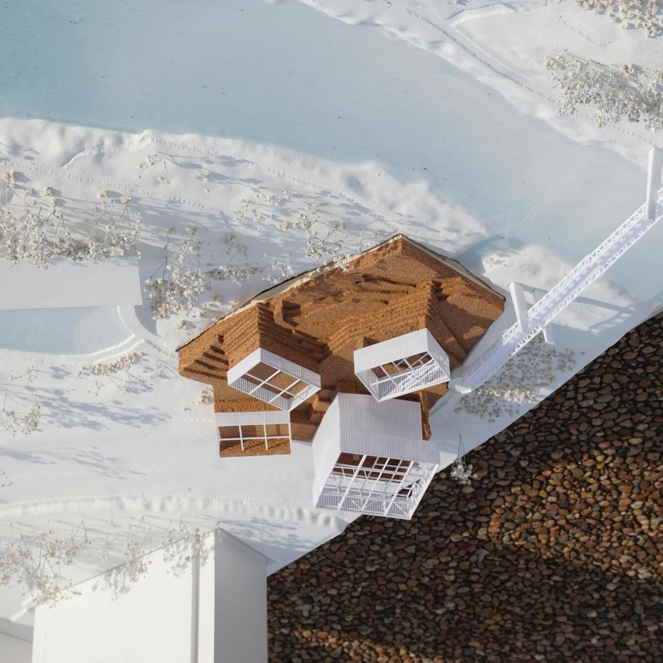
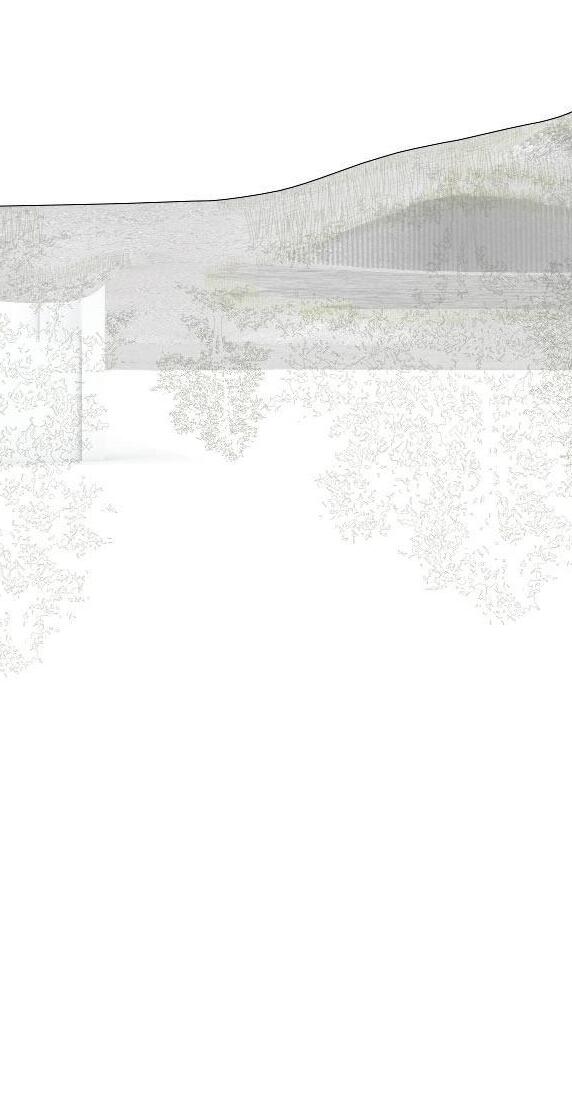
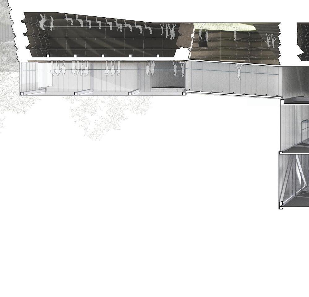
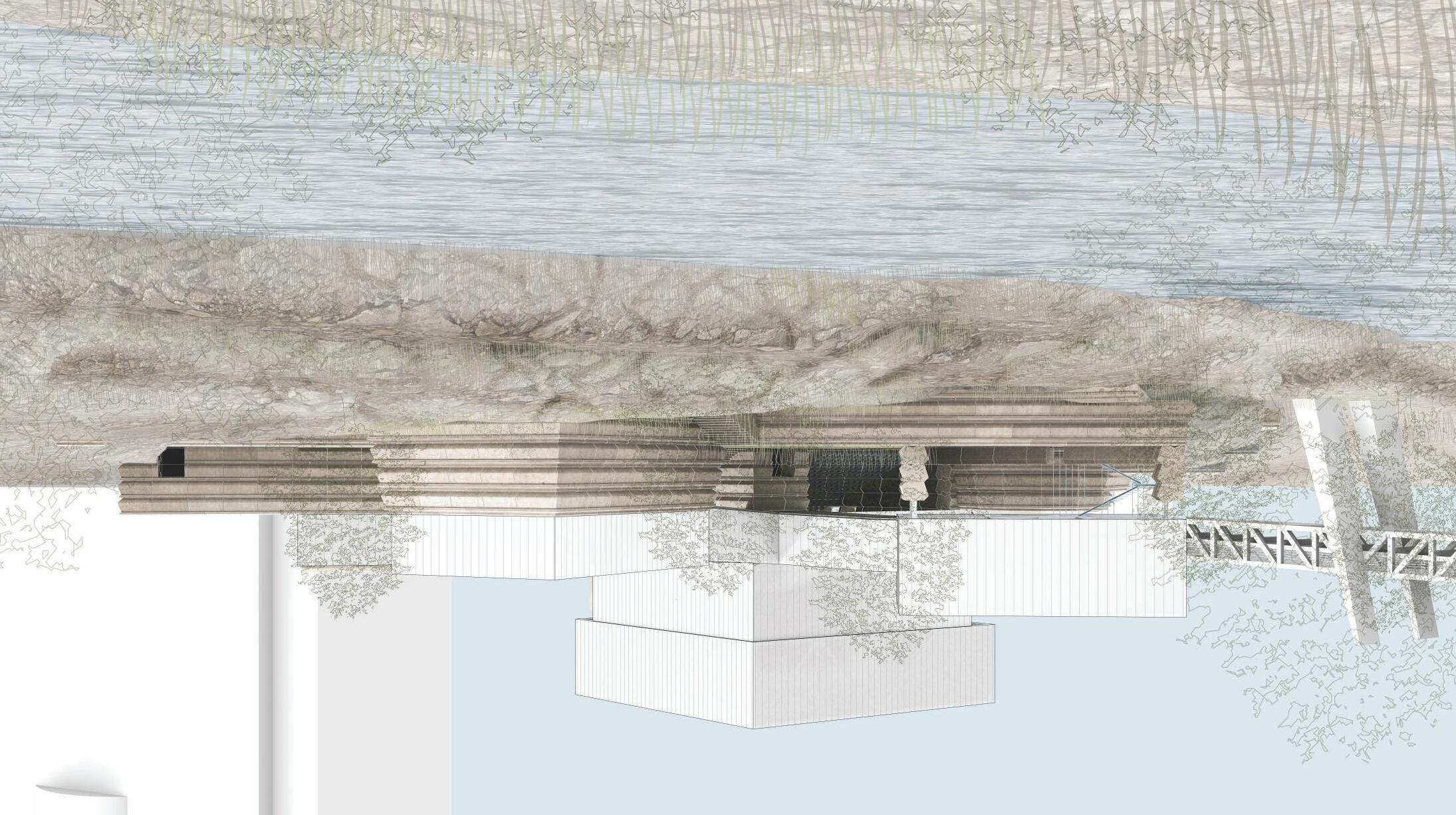
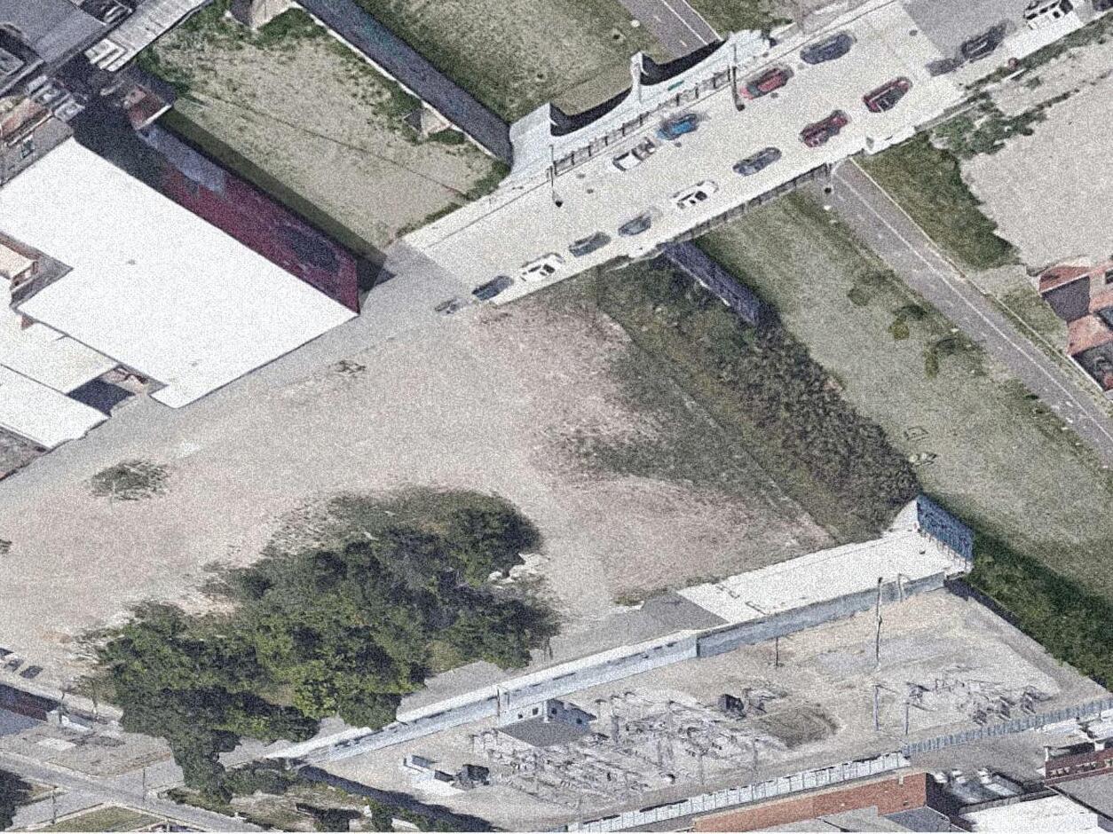
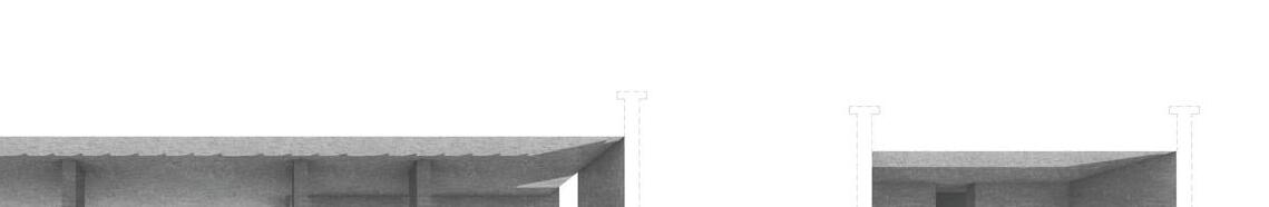
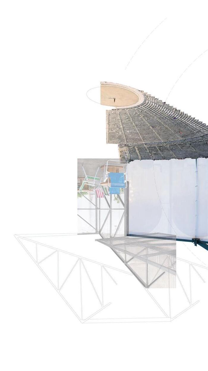
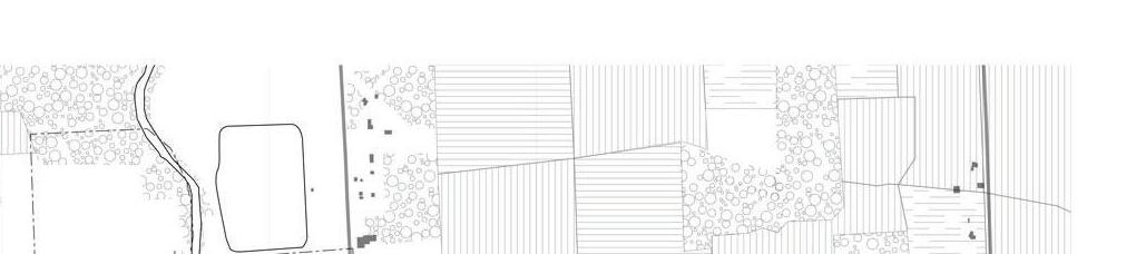
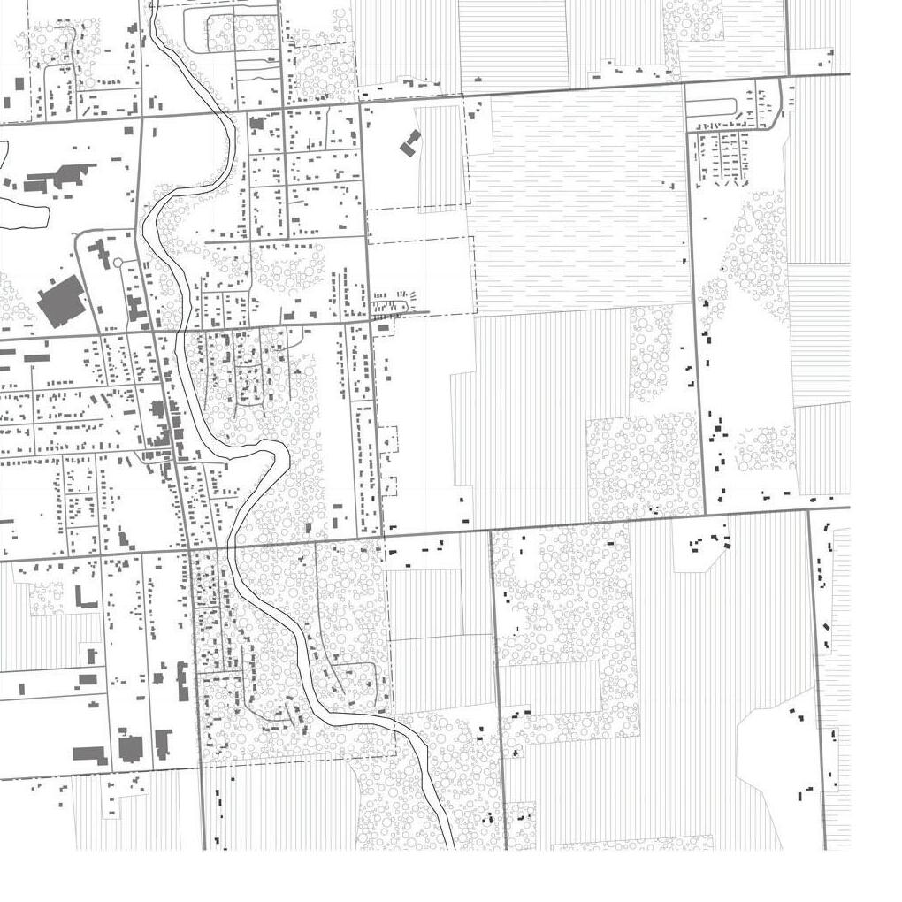
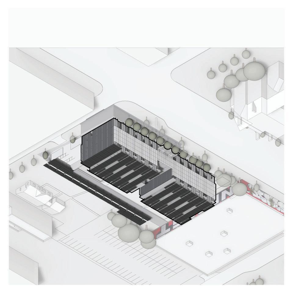
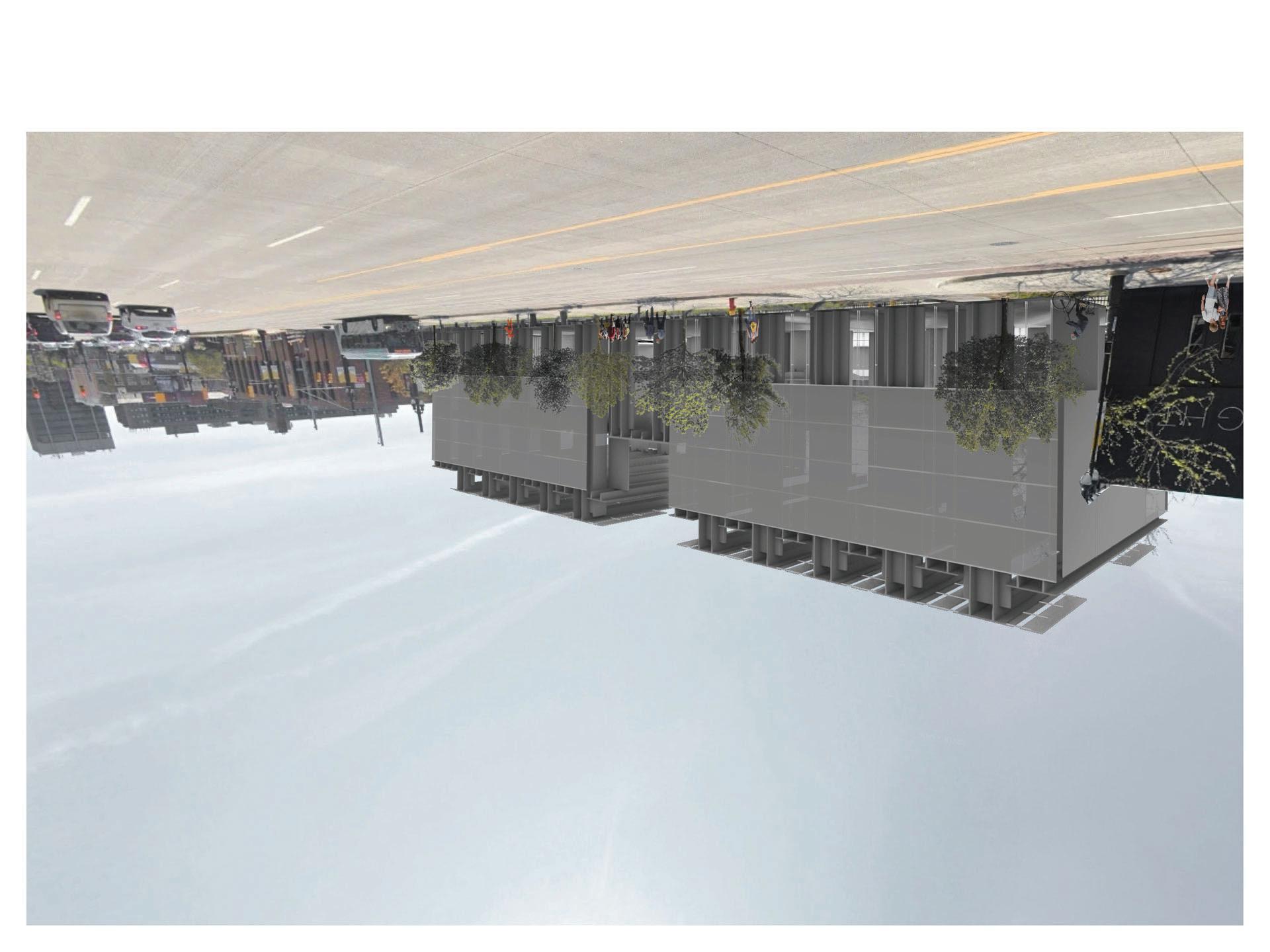
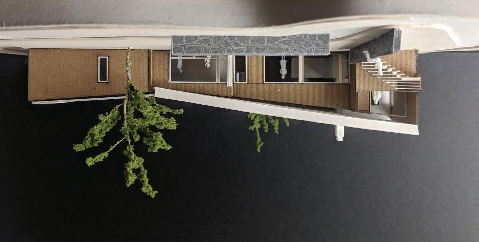
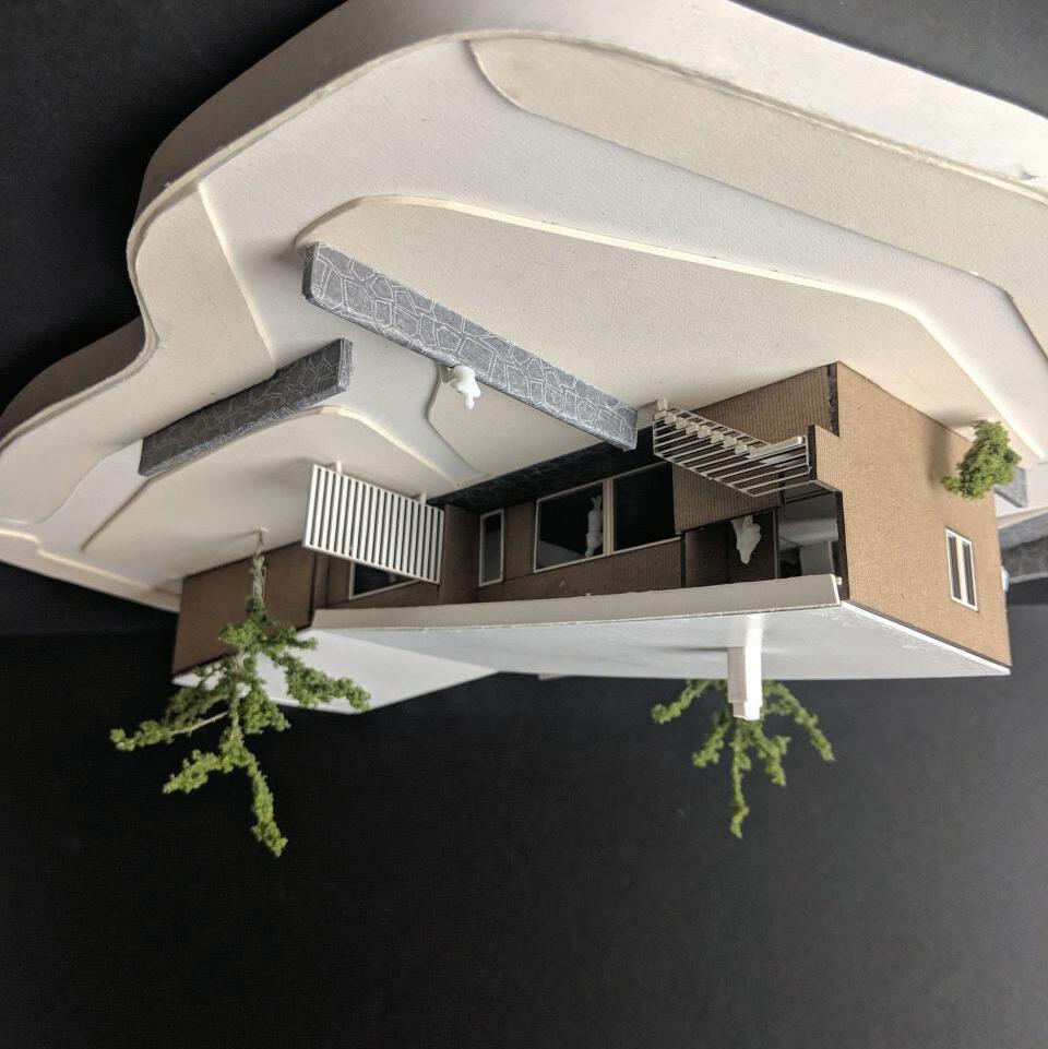
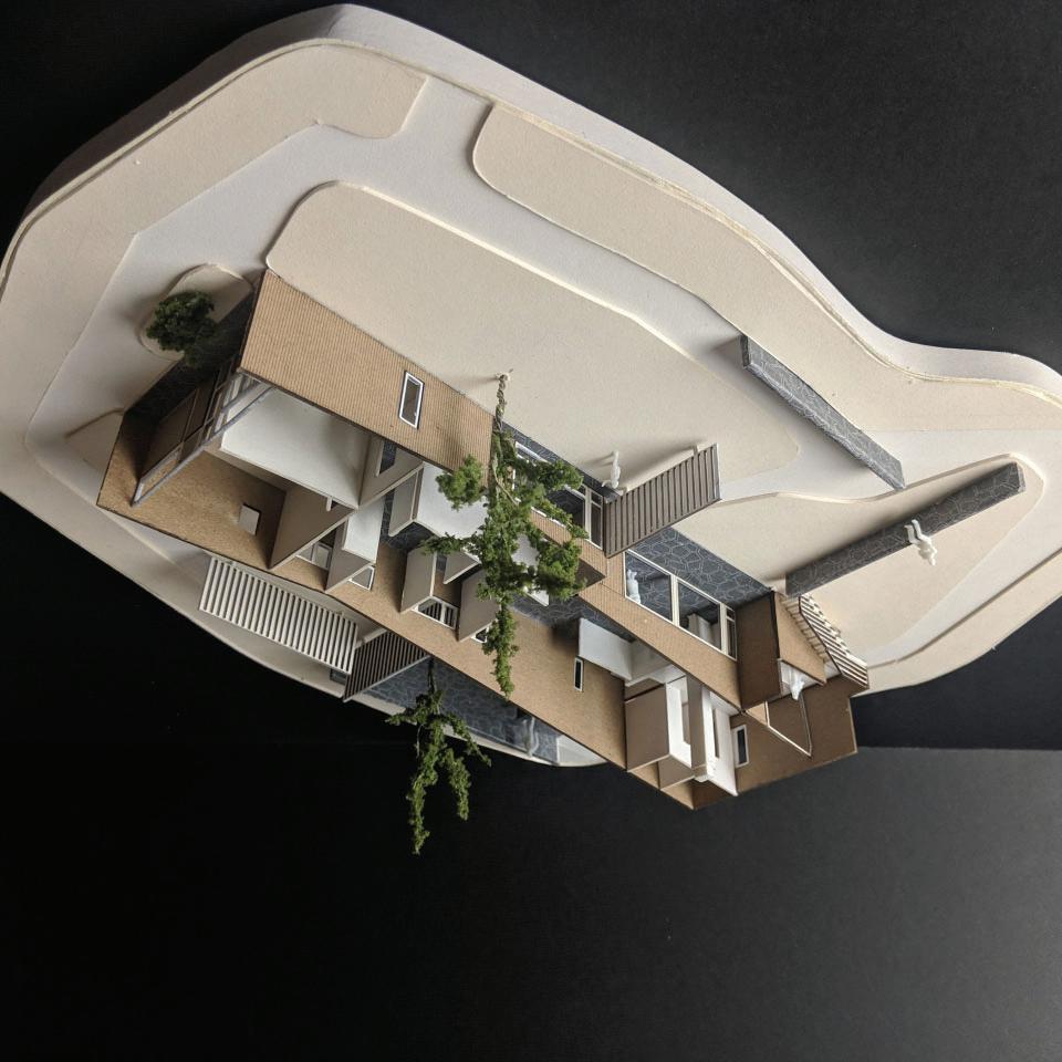
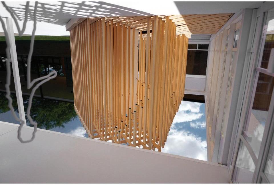
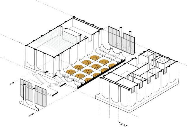
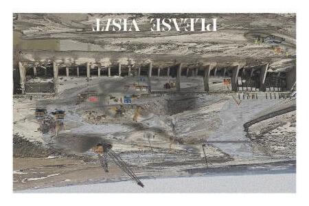
Houston Texas sits within Harris County whose area is largely flat sans the bayous that scar the landscape, providing rare moments of shifts in elevation. This is a natural border in the city, which the urban landscape accepts, a snapshot of the bayou in time, which is petrified by the Army Corps of Engineers’ concrete gutters. The geometry of this gutter is absorbed into the city’s fabric, futhur emphasizing this border. This project sits on this atypical condition, straddling the city and the bayou which often floods. ‘I.C.H.’, Immigration Center Houston, is a place of celebration for all that immagrants to America provide and achieve.
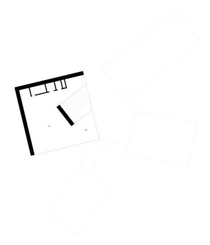
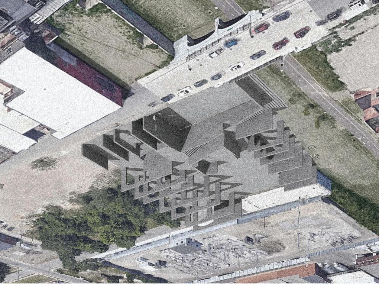
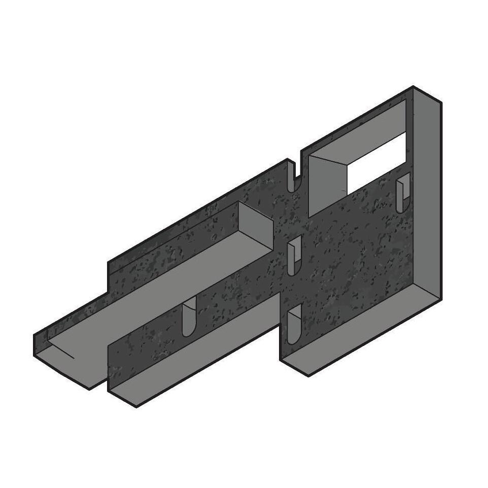
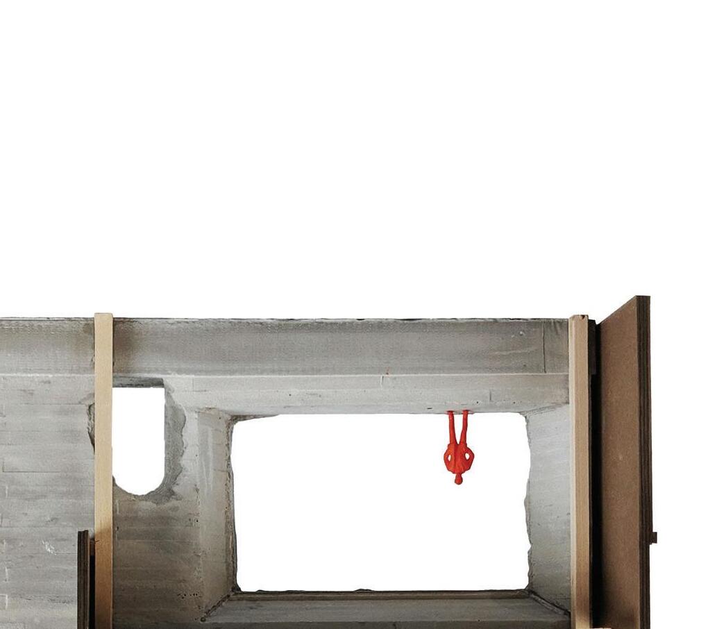
← AXO / PLAN ↑
A Wall is built up, to formalize this break and distinguish itself from the city. In plan, the building strategically folds out onto the landscape. These footprints are supported by retaining walls below, and provide a secure place to build up upon, and rise up to divide and define the form above.
 Core Studio 3 - 2022 - Prof. Carlos Jimenez
2
↑
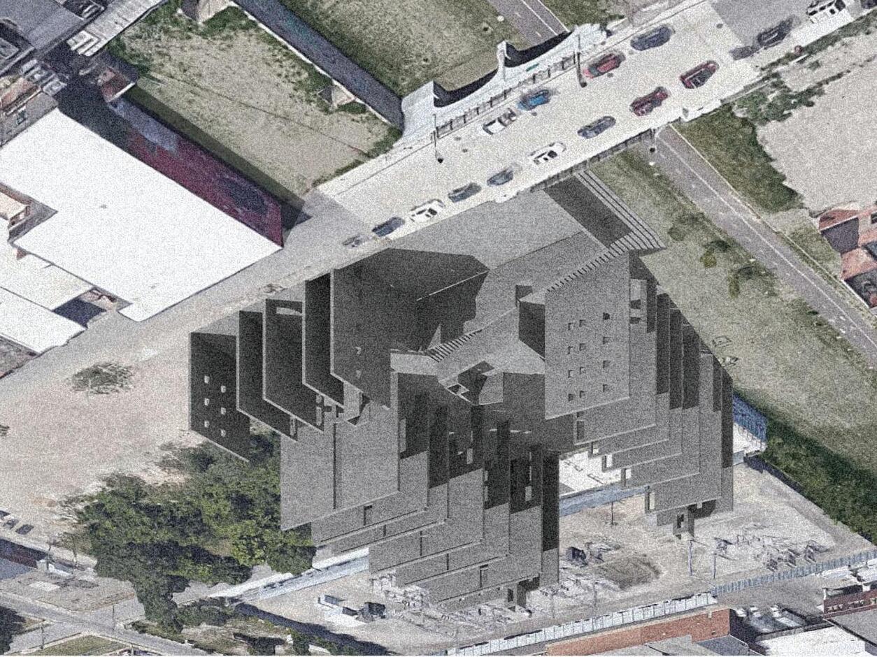
S ELEVATION / N ELEVATION →
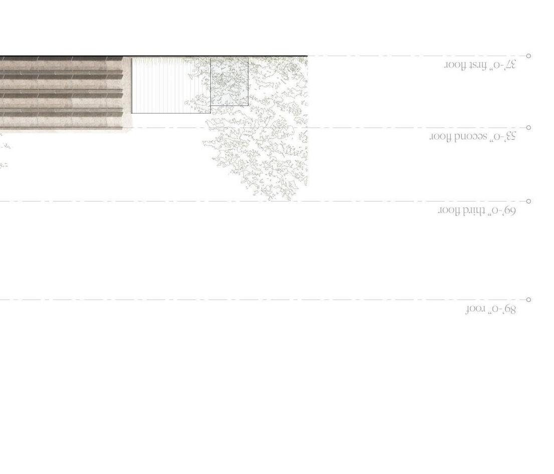
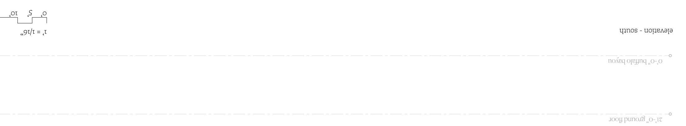
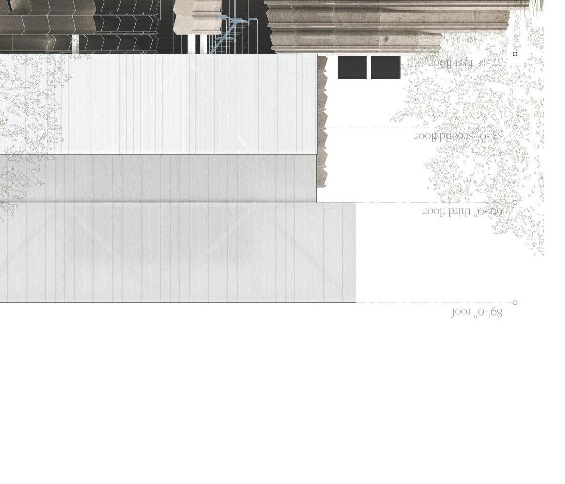
The wall that breaks the building from the city reads simply from the southern side, where you would approach the building from the city. From the Bayou in the north, the buildings formal reading is more porous and fragmented. The singular entrance from the street is contrasted by the multiple paths down to the Bayou.
3
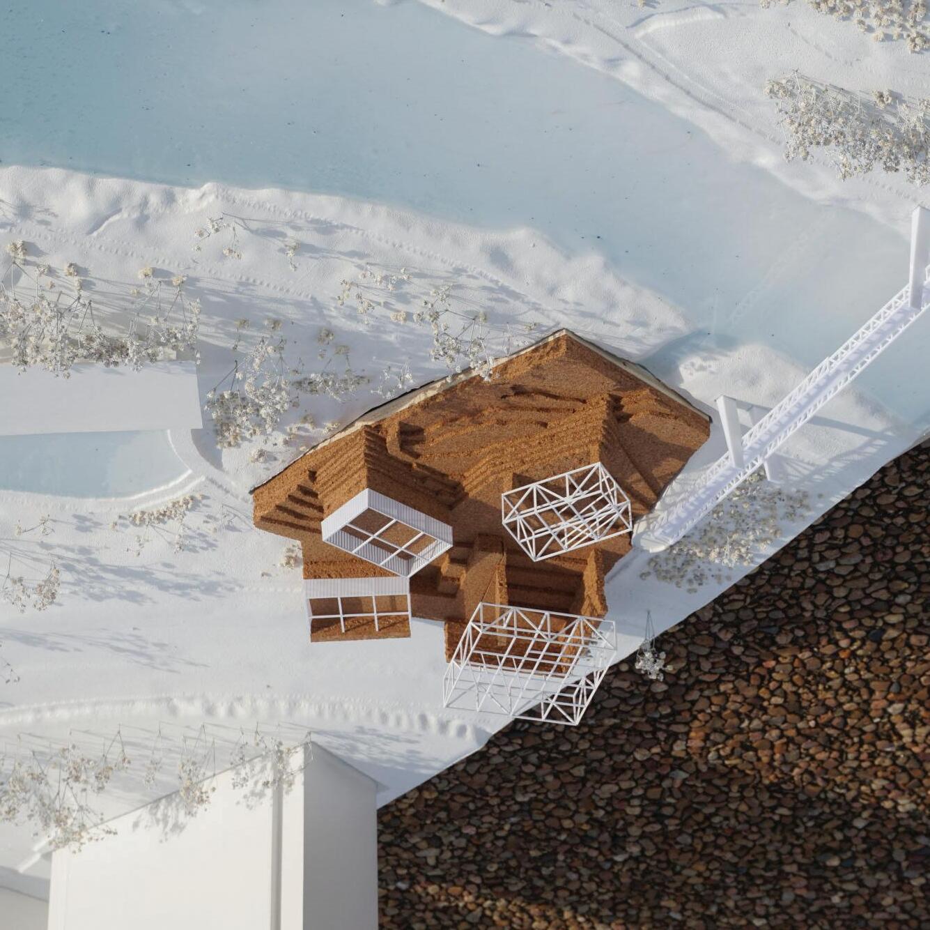
The site model was built as a class, with the site itself taken out, for our own individual models to be placed into. Those who contributed to building the class’ site model are Nino Chen, Juliet Hollister, Dana Kim, Vinati Kokal, Wenjie Ma, Feyza Mutlu Bailey Stevens, and Jeremy Thorn
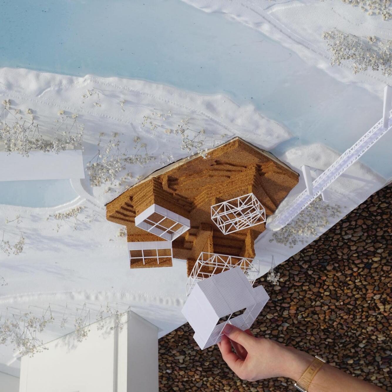
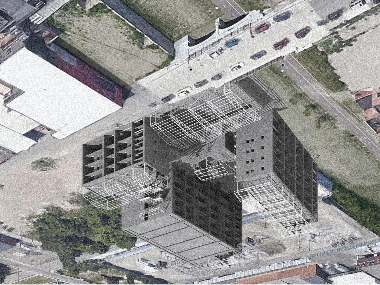
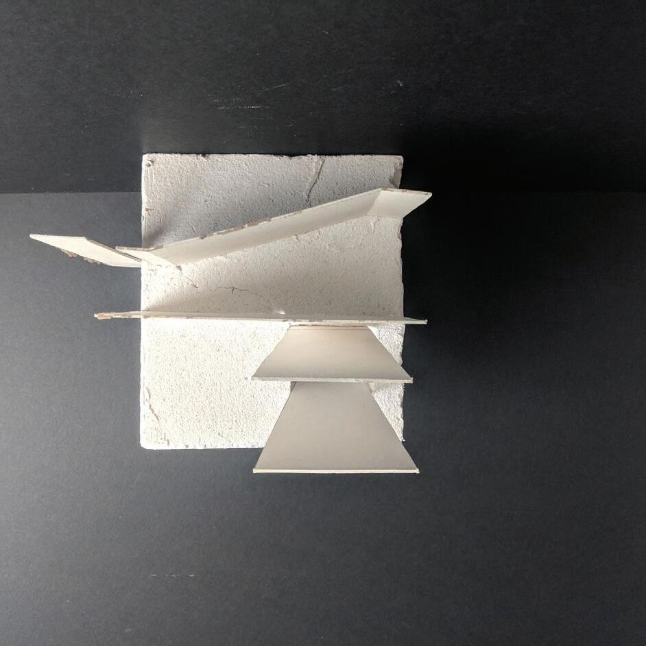
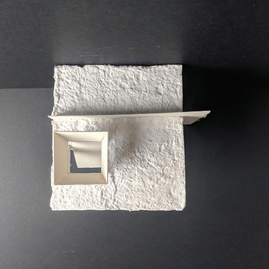
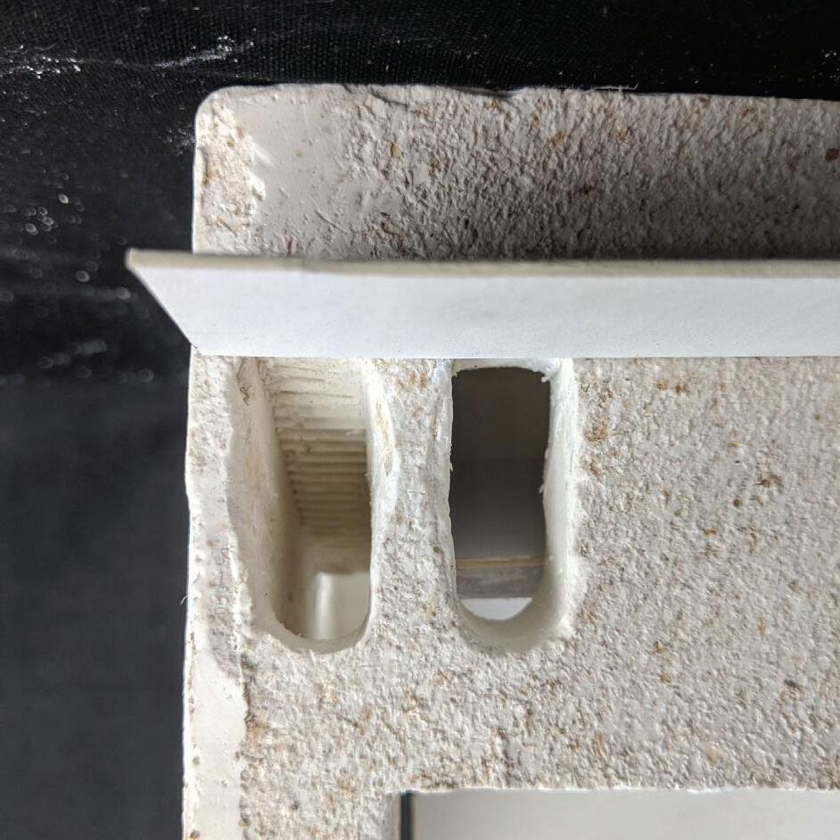
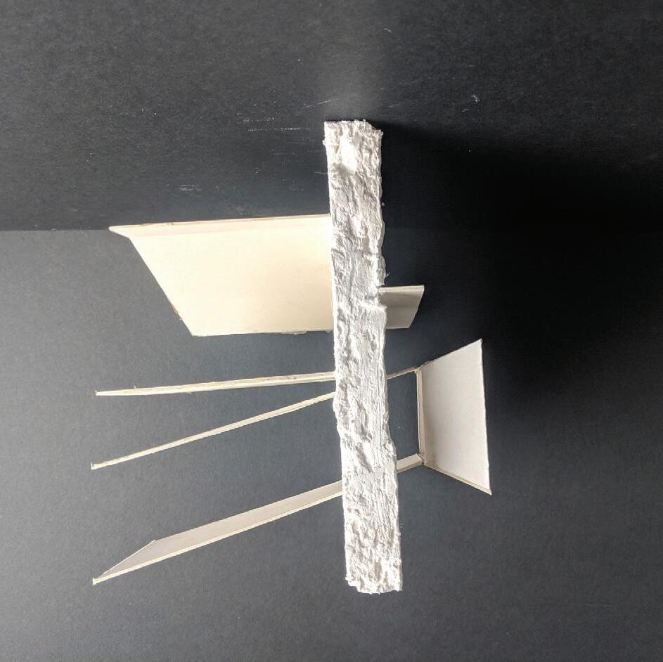
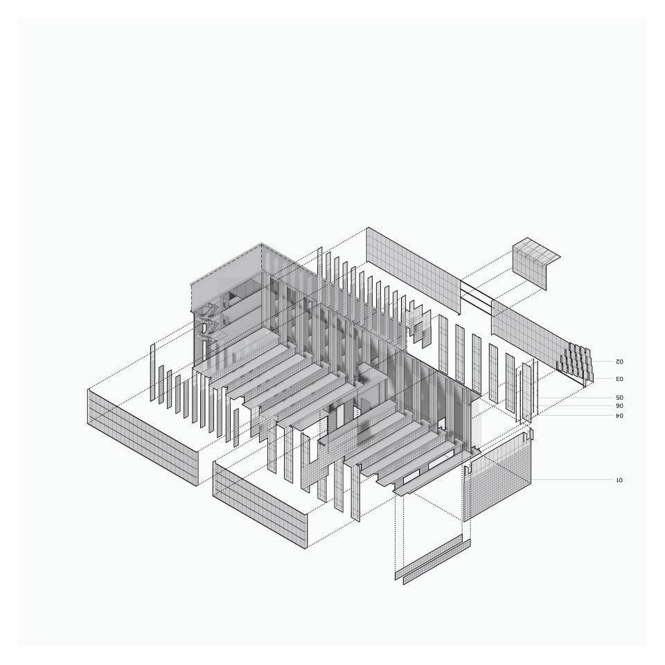
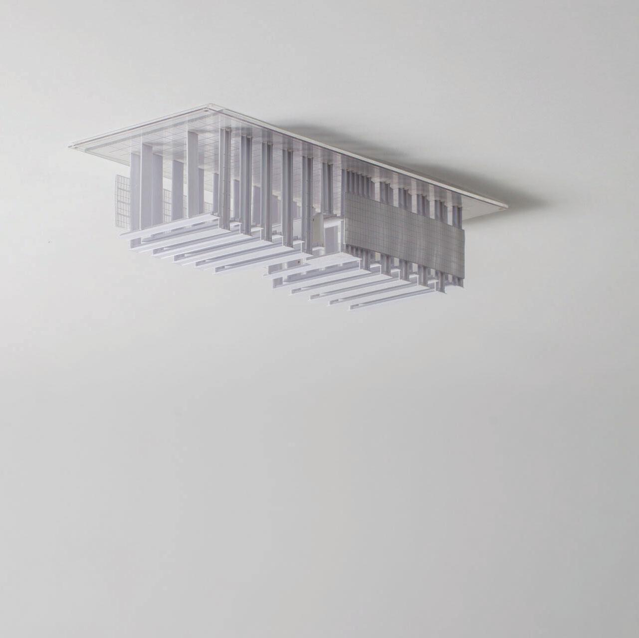
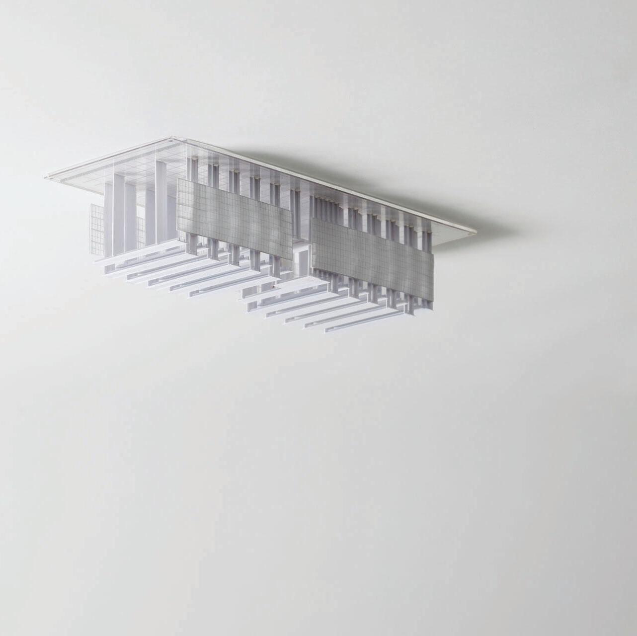
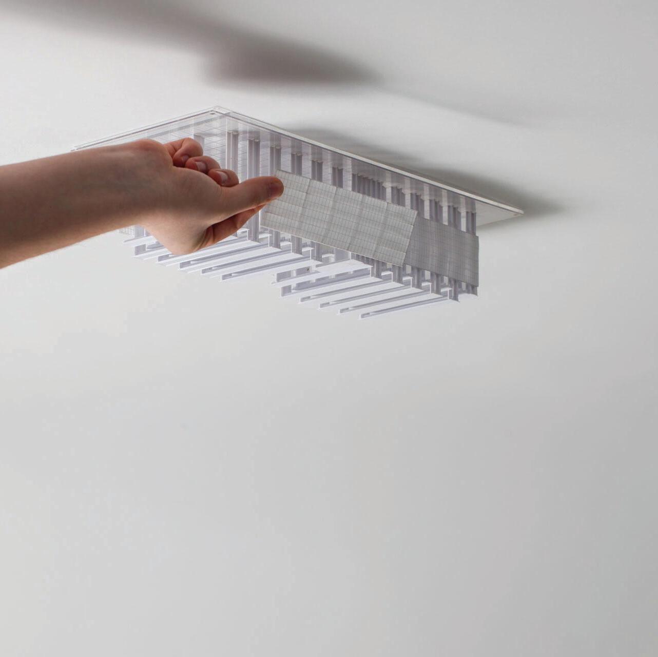
← BLOCK LOGIC / SYSTEM MODEL ↑
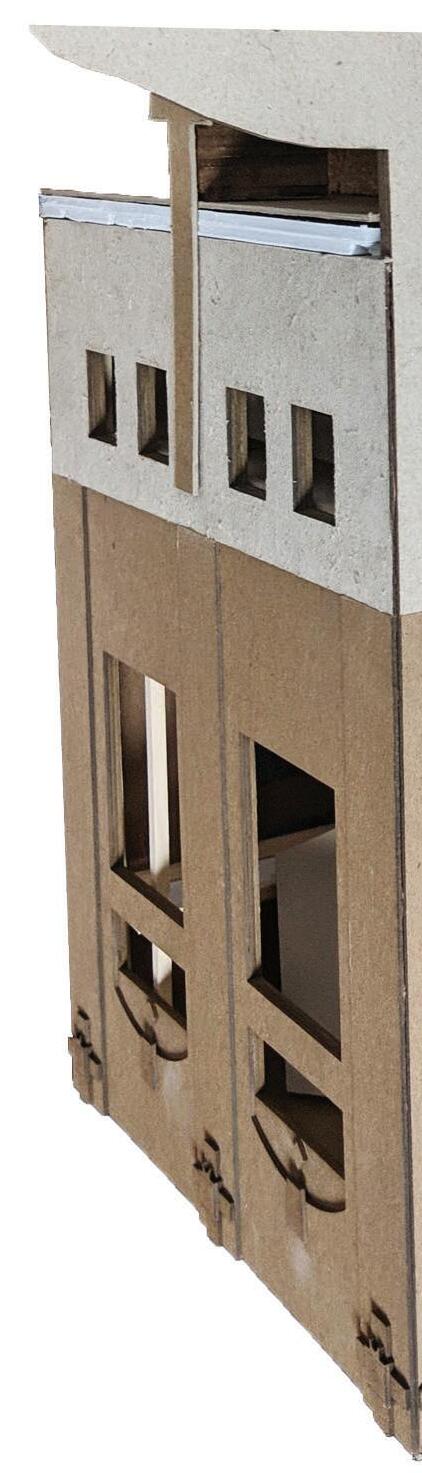
The model clearly delineates the ground and building conditions, accepting some of the occupiable space as part of the ground. Both the ground and the walls are read as the same material, while the steel structure that sits upon those walls is a light skeleton, resting on top. The building is then lightly clad, providing further contrast in these two building tectonics.
01 1 0 02 0 2 0 03 3
4
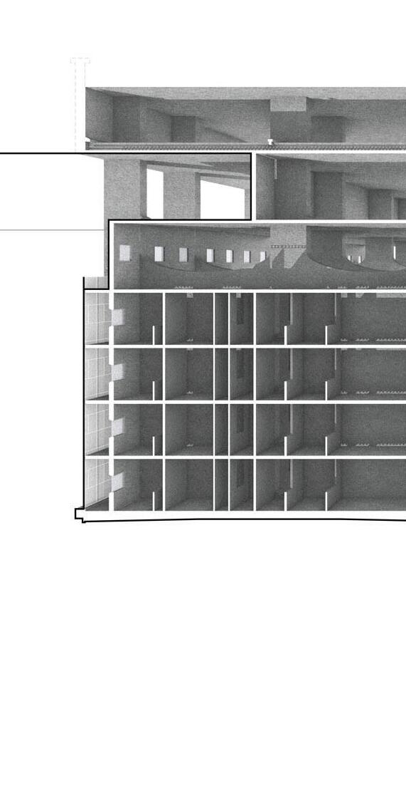
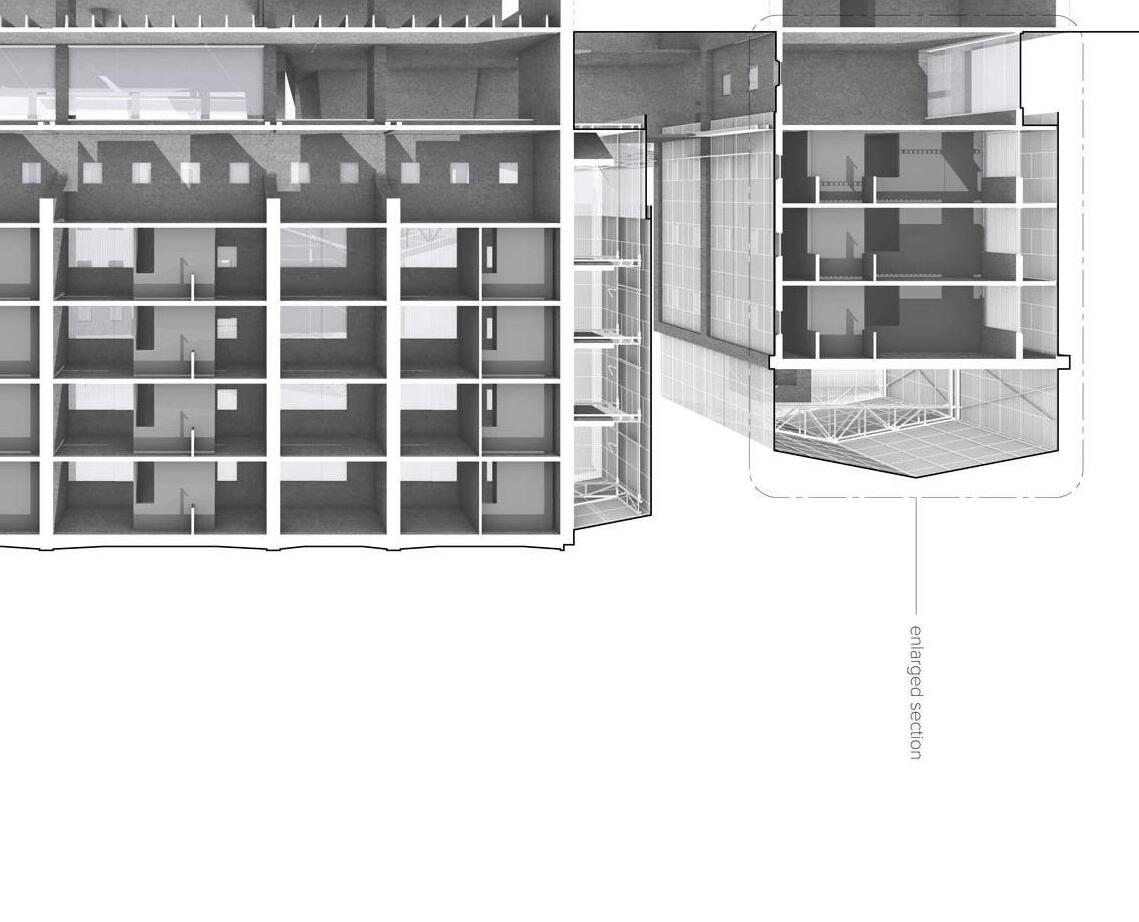
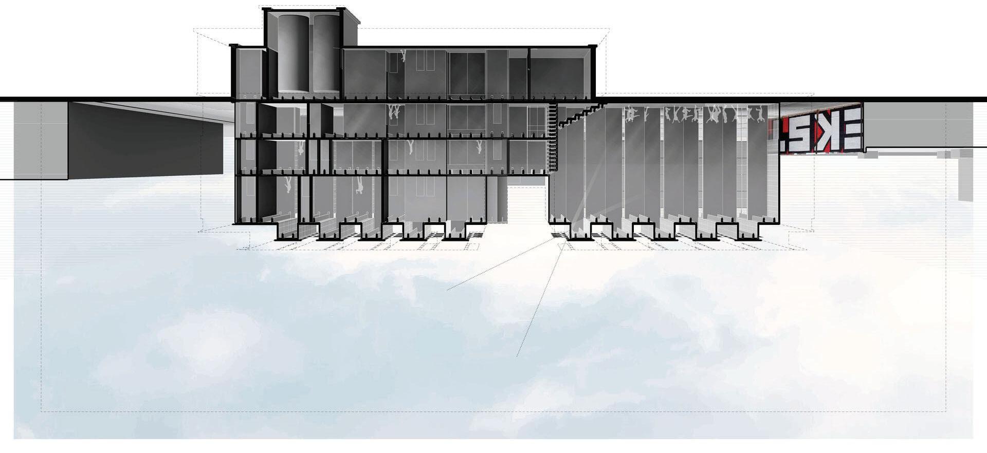
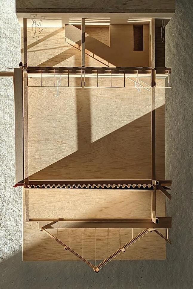
W-E SECTION / E-W SECTION →
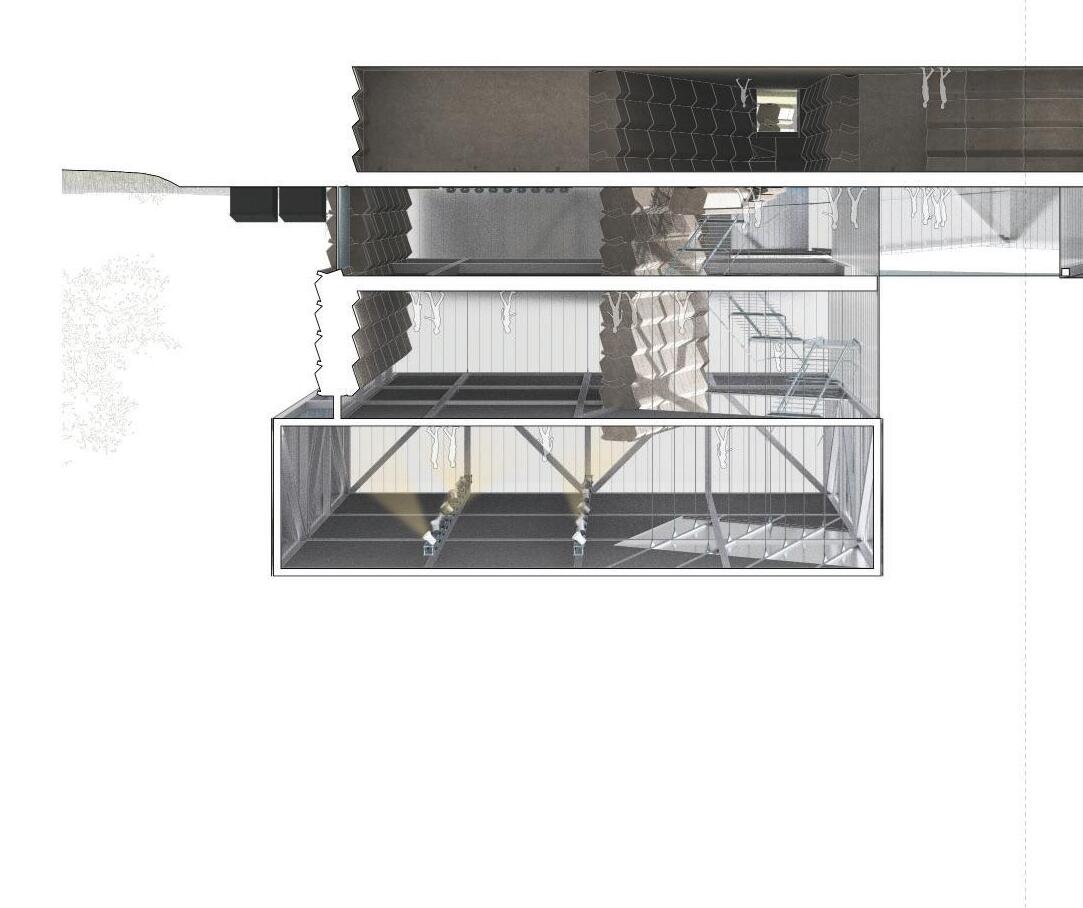
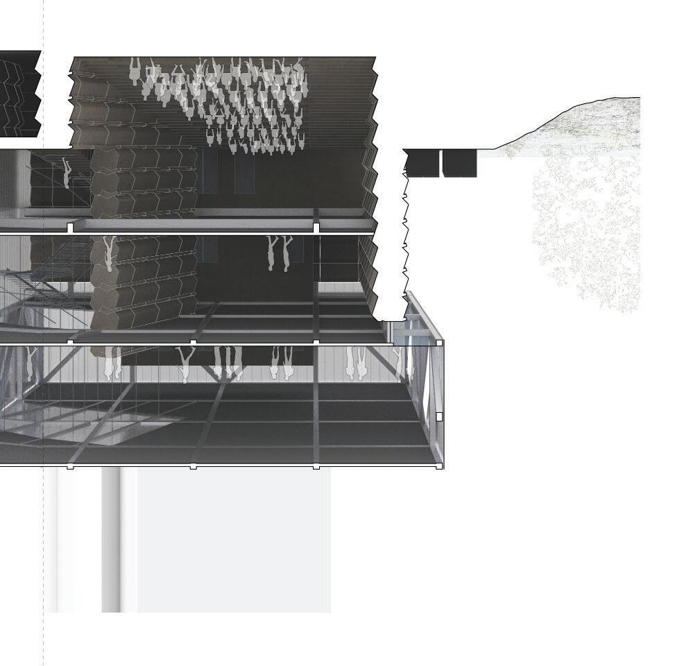
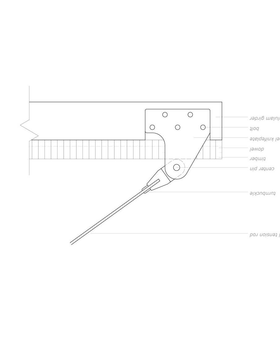
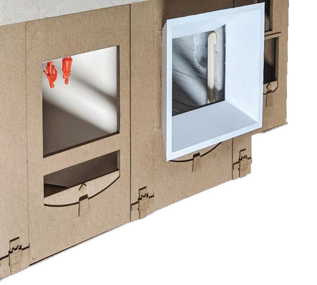
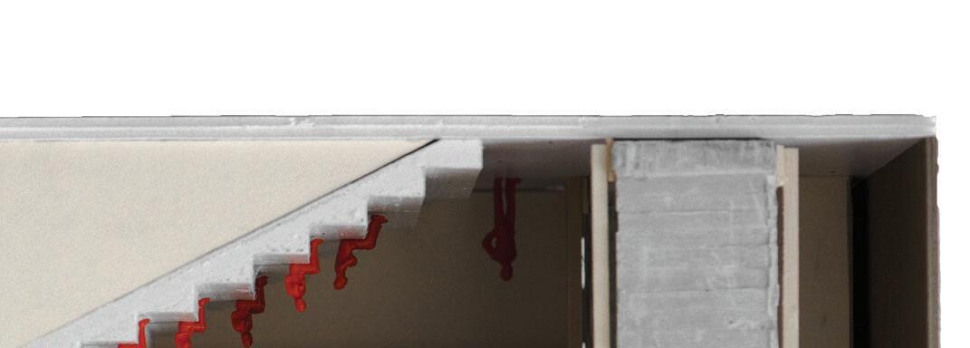
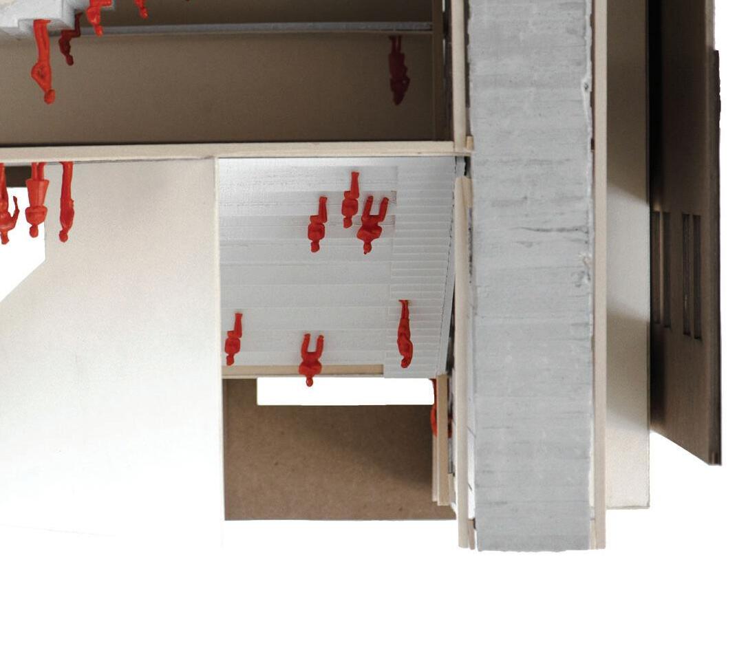
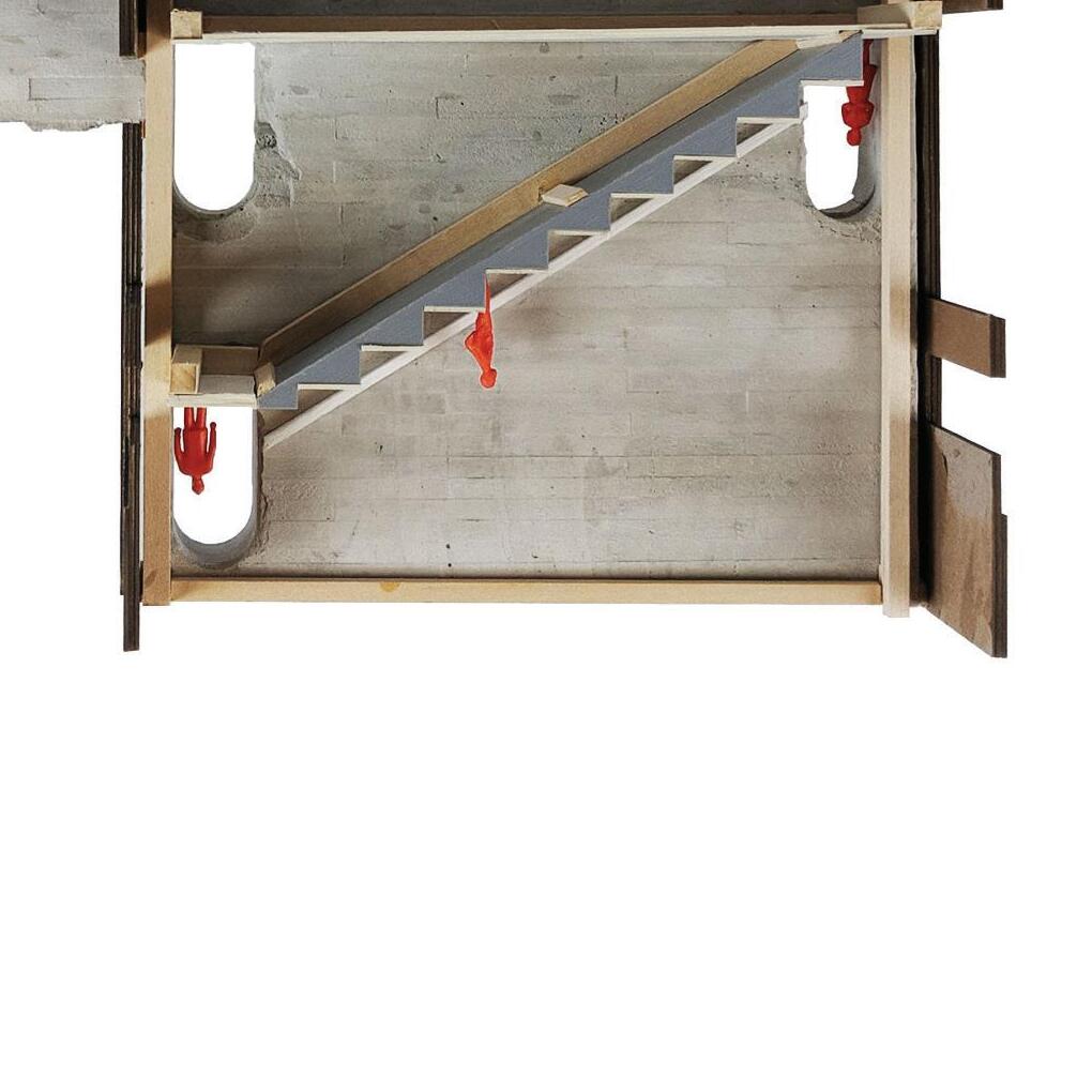
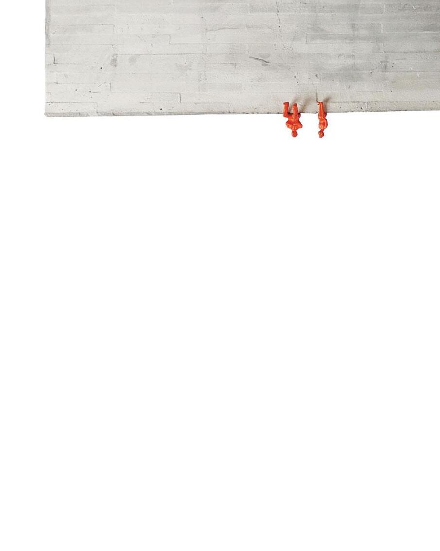
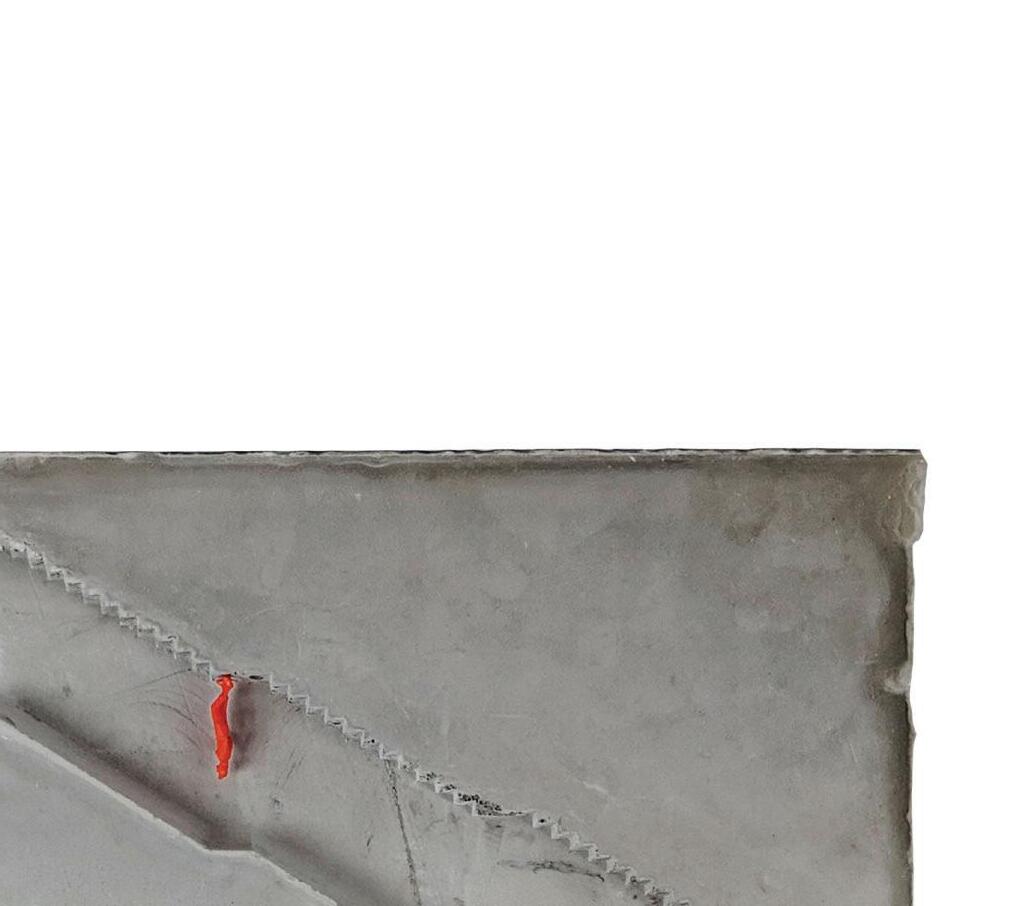
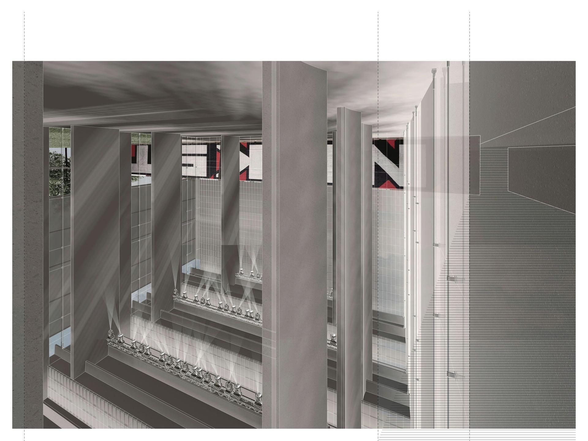
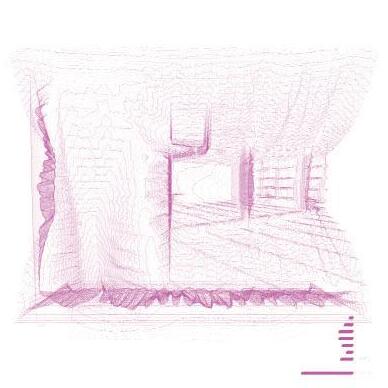
The distinction between concrete wall, and steel structure and its divide in elevation is more subtle than a singular line. The inital idea was to align this division with the 100 year floodplain to secure program below the floodplain, but allow program above it to be open. The 100 year floodplain however, is arbitrary and as of late, has been broken much more often than every 100 years. Thus, the line is blurred. Walls break above this plane, and steel structure begins much higher than the floodplain. Steel only exists on top of concrte however. That is to say, when steel elements are below the walls they sit upon, they hang from the steel above rather than secure themselves to concrete that it shares elevation with.
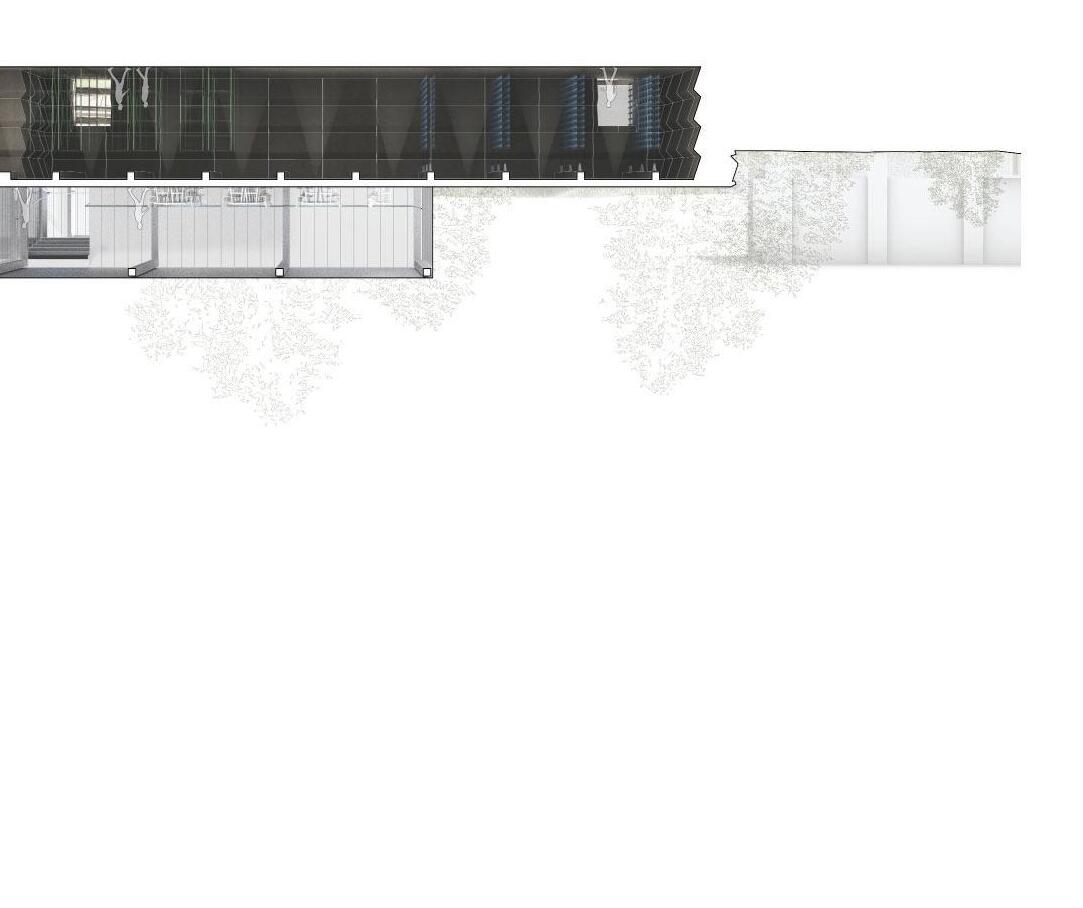
See the stairs in these sections for example. They hang from the top most sets of trusses and extend down to the lobby, where the last riser is missing creating a gap between the concrete and steel, distinguishing what is resting on the earth, to be flooded, and what is hanging from above, to be spared from the damages.
↑
5
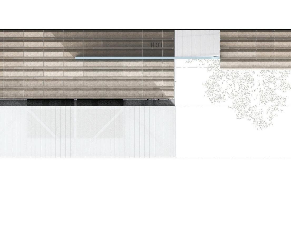
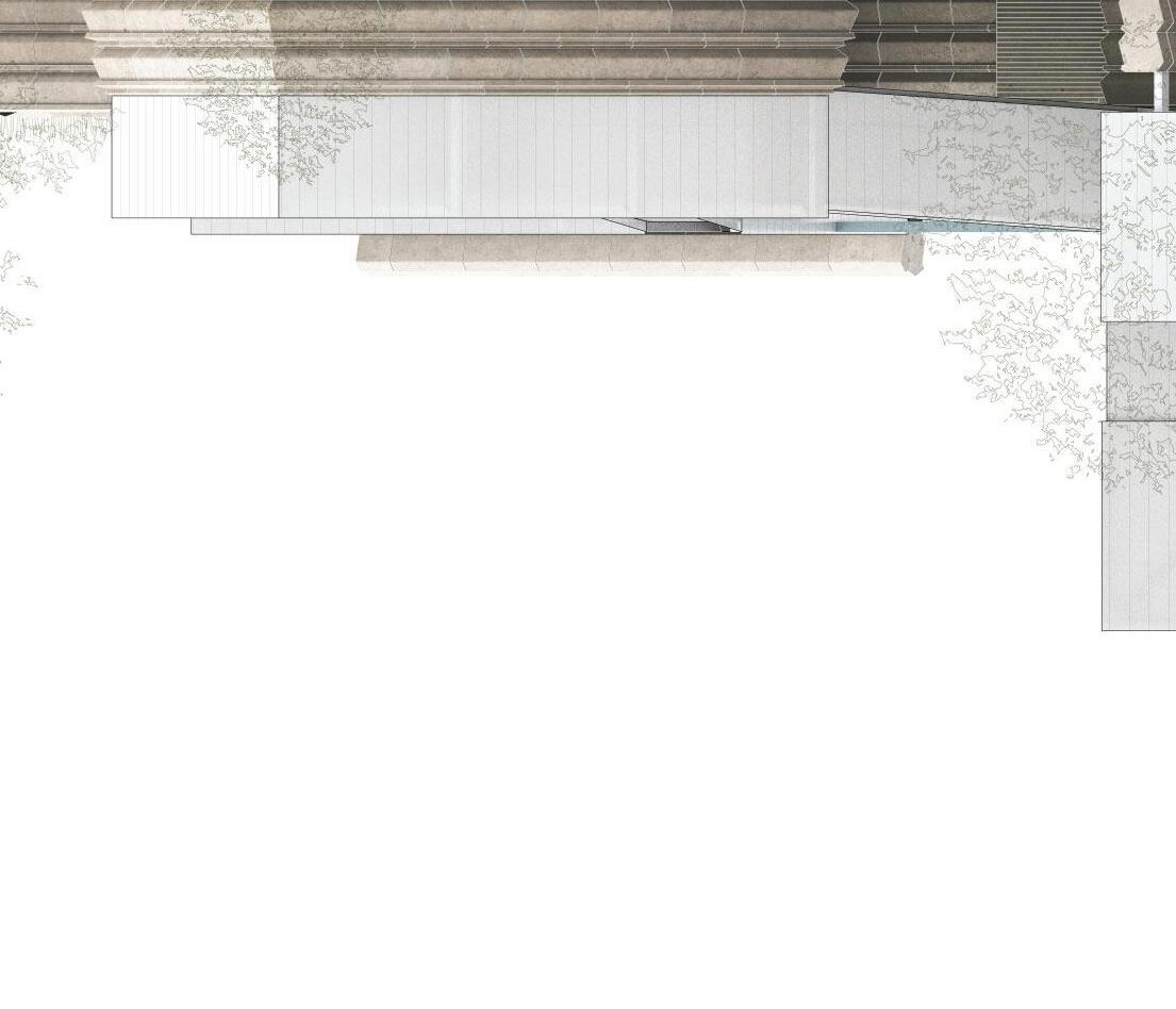
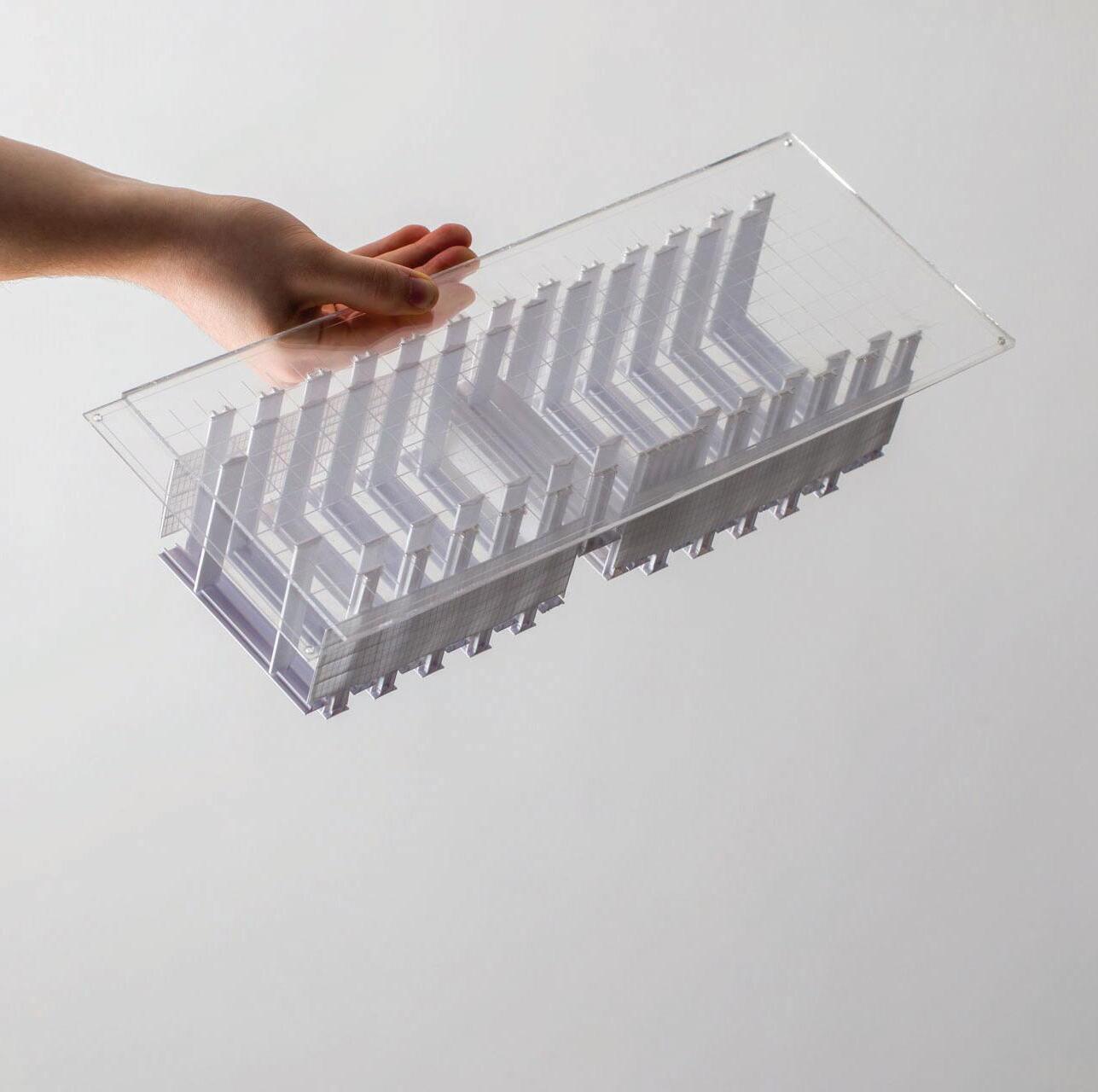
The primary cladding of the building is made of polycarbonate and kalwall materials, all translucent, with varying levels of transparency, however on the exterior they are mean’t to be read as a singular, light and airy material to contrast the heavy gestures made by the concrete.
 ↑ AROSS BUFFALO BAYOU
6
This was the last studio in the sequence, and served as a ‘comprehensive’ review of the different facets of the architectural dicipline explored in previous studios.
COMPREHENSIVE DESIGN
Comprehensive Design - 2021 - Prof. Daniel Faoro
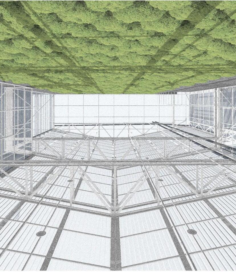
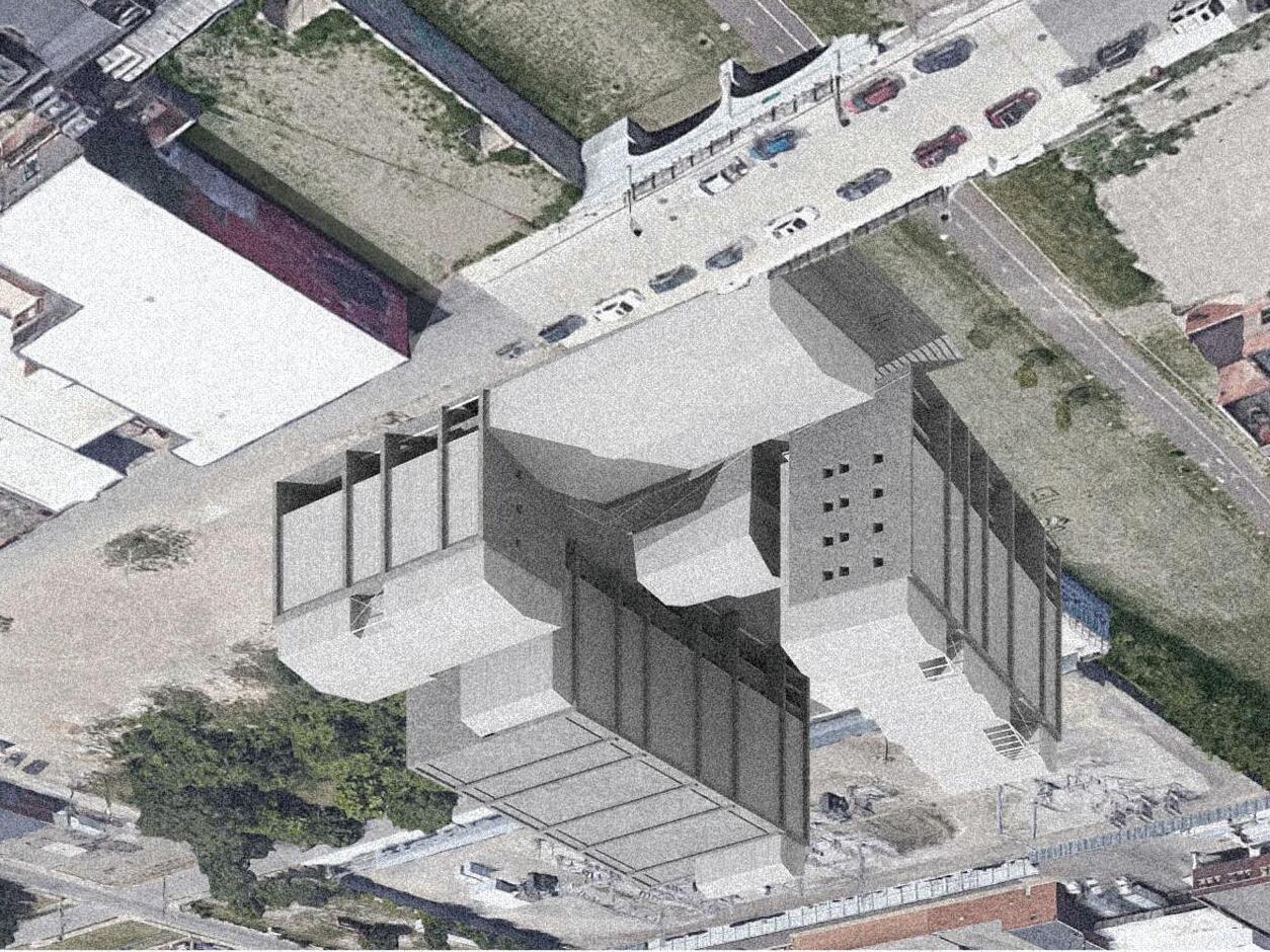
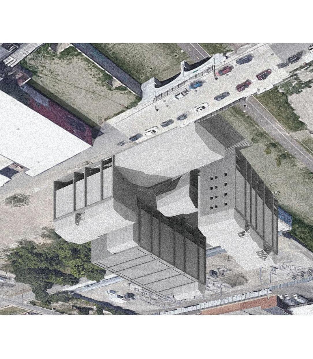
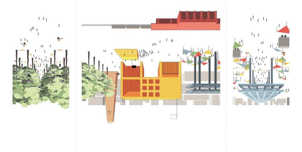
An objective of this project is to situate a large building with many programs into a unique contexutal environment, to maintain sustainable building and construction systems, and to facilitate existing conditions both economic and cultural. The given program is vast and complex, calling for a large floor to area ratio relative to the given context. An elemental building approach is taken to break up the large mass into an understandable, readable building mass allowing for nuanced formal relationships to be made.
 ← FROM GREENHOUSE / SITE ↑
7
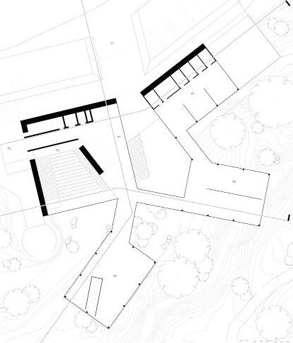
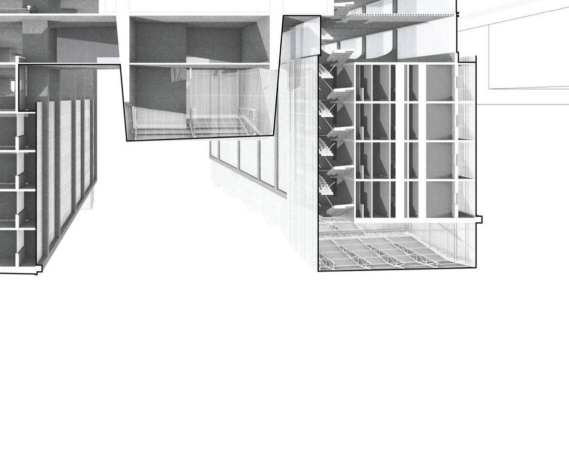
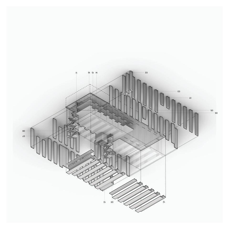
FLOOR PLAN / SEQUENTIAL DIAGRAMS →


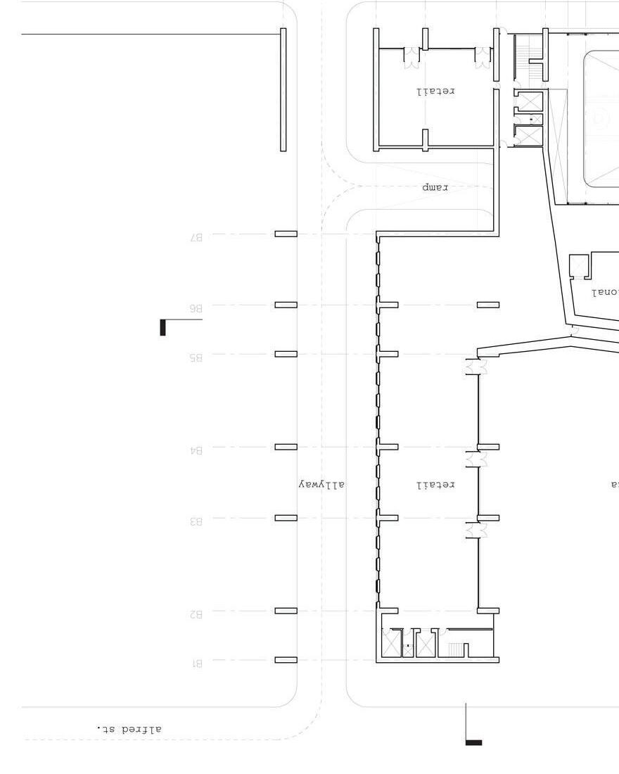
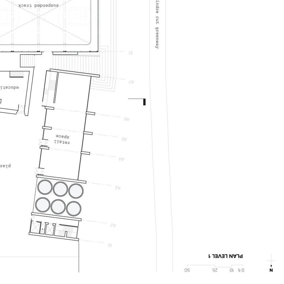
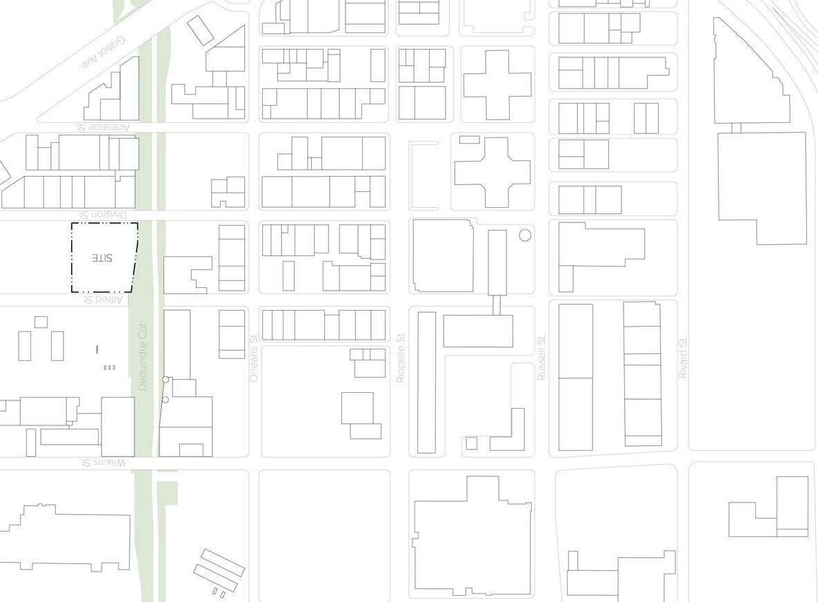
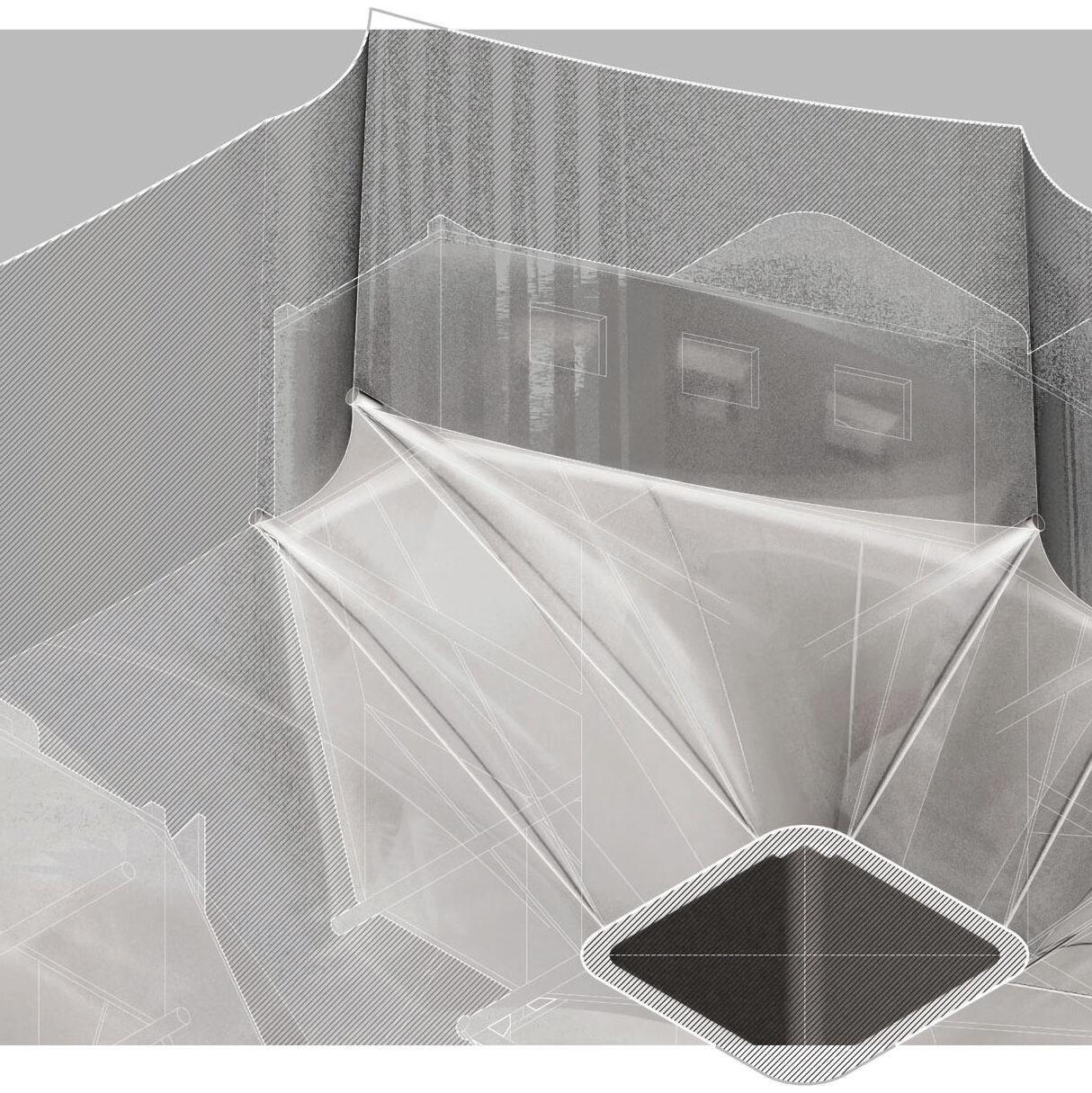
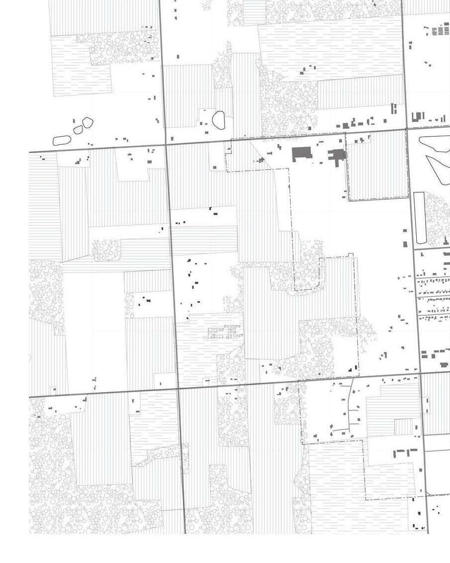
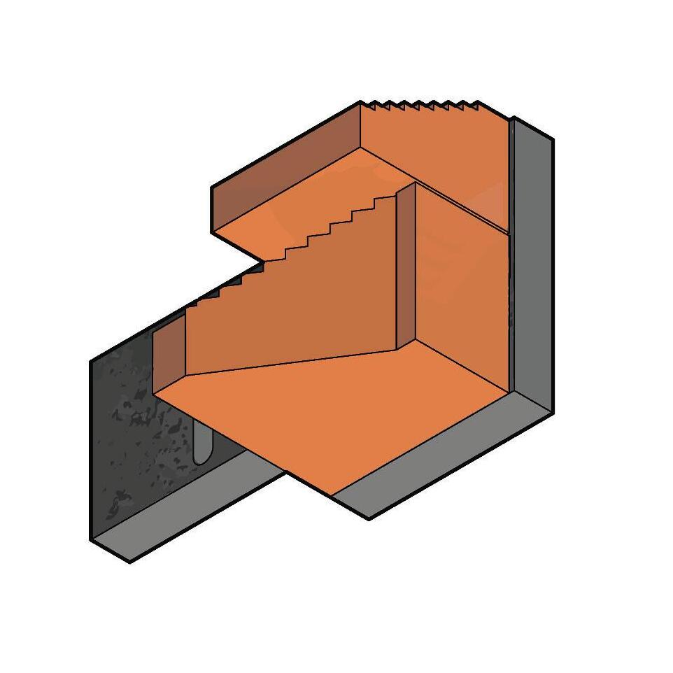
The existing site’s most significant conditions include its sharp elevation change on the west side, shallow elevation change on the east side, and the immidiate adjacency to the Dequindre cut. Both of these factors need to be negotiated by the proposal’s strucure. It should also be recalled the Eastern Market District’s extensive use of masonry shear wall structures and the subsequent mural culture that these walls help to facilitate. The ability and neccesity for retaining walls and the canvas-esque nature of shear walls should determine the formation of the proposal’s structures.


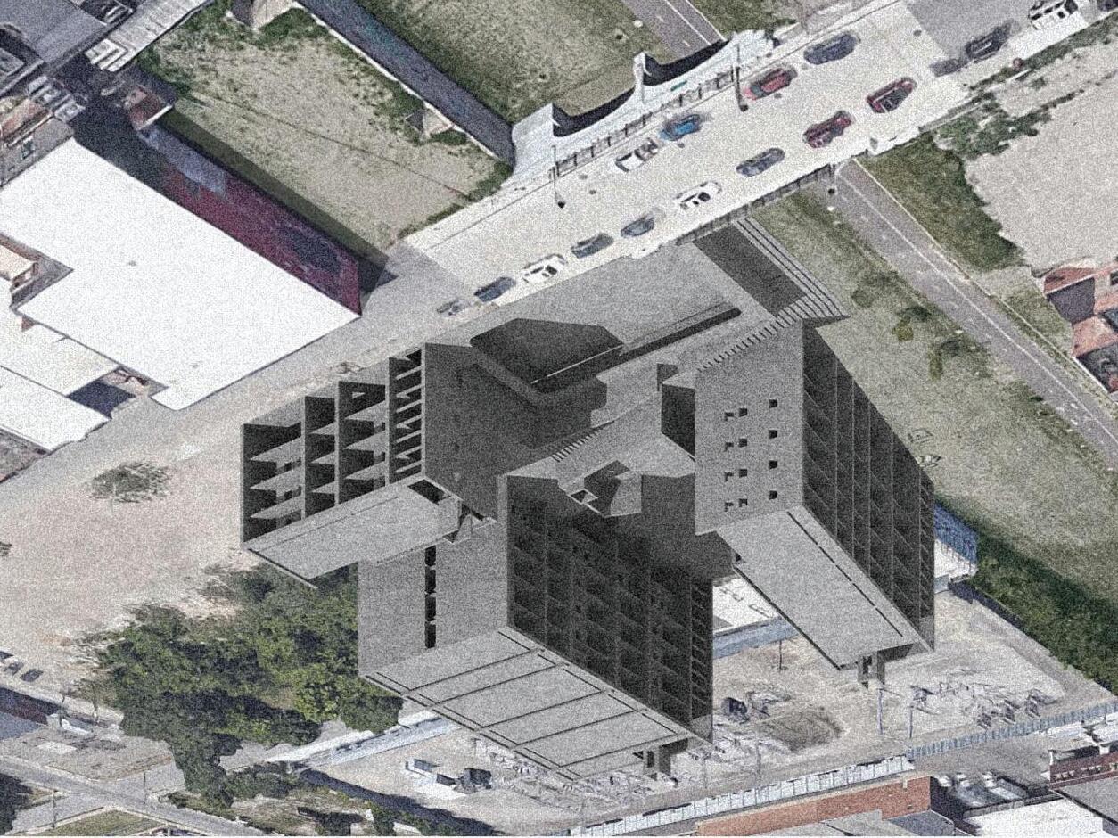
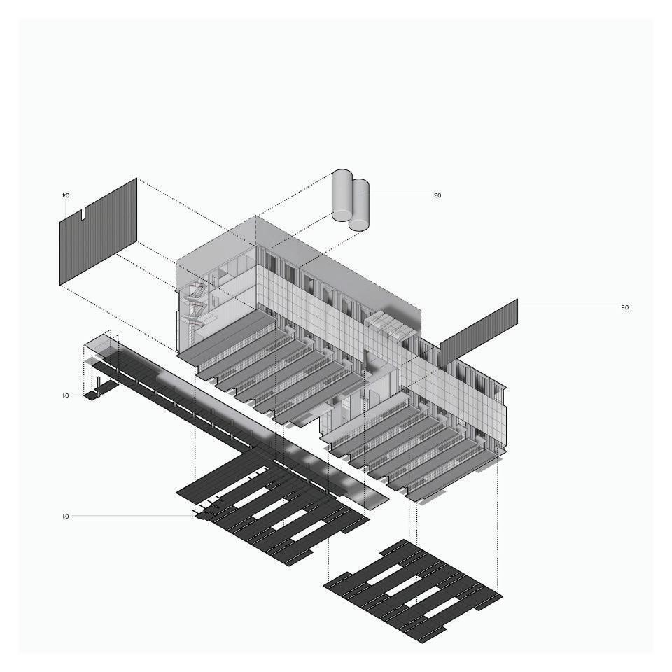
The first stage of construction, after site preparation and excavation is the pouring of the primary site cast concrete massing. This stage firstly retains earth, sets up the shear wall system’s rythym that will be repeated above, and creates the unique shapes to define elements such as the educational space in the center, and gym space in the south west quadrant. The walls’ rythym is determined by the residentials spaces above, and their spacing is determined by what size of unit is above. In order to reconcile the more modular residential units with the larger footprint, open space retail and office spaces, the walls are punctured by large archways whose profile is taken from the multiple bridges that span over the Dequindre cut. Lastly, the site cast massing includes the monumental stair that connects the Dequindre cut grade to the street level grade, and terrace grade on level two.
↑ FIRST
03 3 0 05 5 0 02 2 0 04 4 0 06 6 0 8
← FROM DEQUINDRE CUT / UNIT PLAN ↑
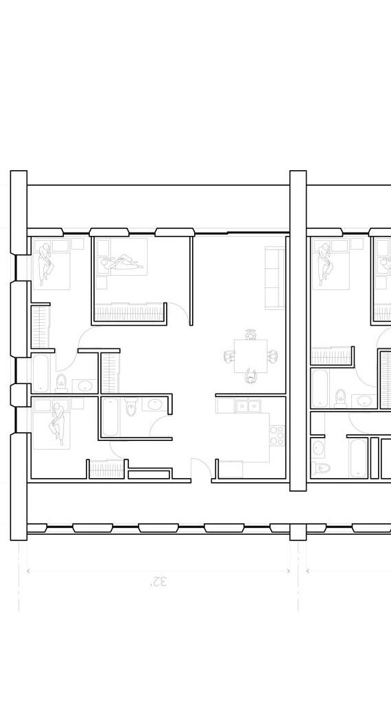
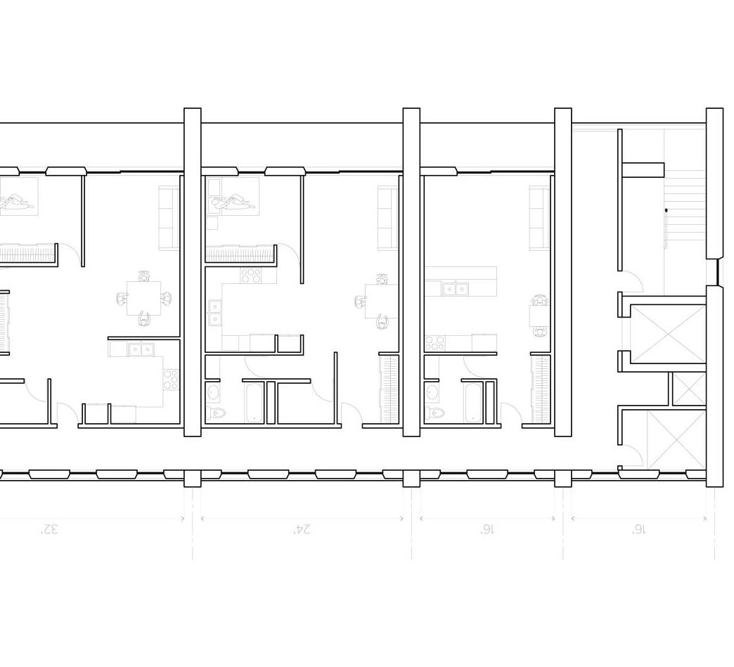
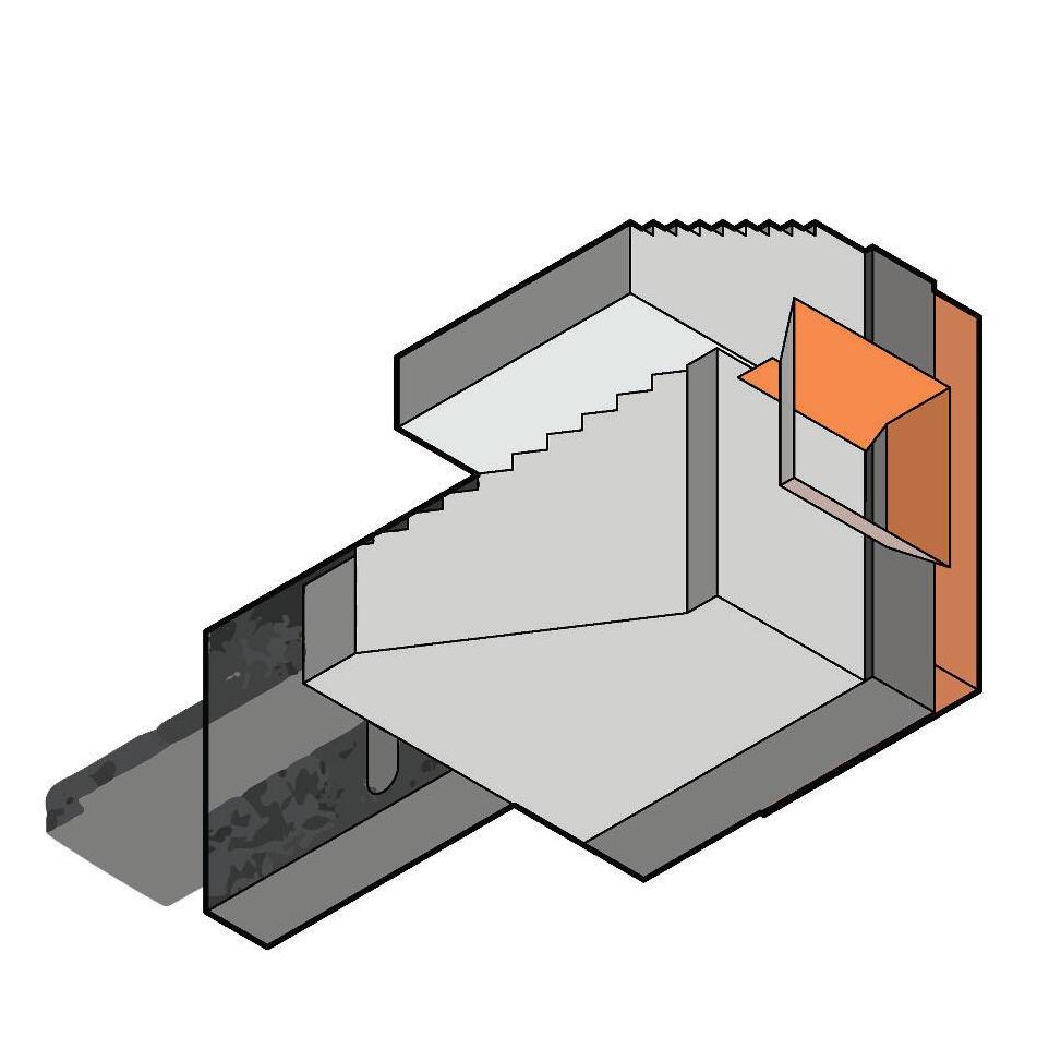
Pre-cast hollowcore concrete slabs are installed next, spanning perpendicular, and between the previously erected site-cast and pre-cast concrete walls. The slabs also vary in length given the rythym of the walls, but still maintain an economy of scale because of the typical 16’, 24’, and 32’ spacings determined by the residential units. Similarly, pre-cast beams are spanned between the walls in order to support slabs which run parallel to the walls in spaces like cores where precast stair units and typical hollowcore slabs sit. Similarly in the core are pre-cast elevator cores which extend above the wall height to provide access to greenhouse and rooftop spaces for general access and maintenance.
9
E-W SECTION / N-S SECTION →
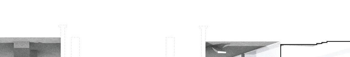
The primary cladding of the building is made of polycarbonate and kalwall materials, all translucent, with varying levels of transparency, however on the exterior they are mean’t to be read as a singular, light and airy material to contrast the heavy gestures made by the concrete. This polycarbonate is of most use on the greenhouse spaces above two of the residential masses, however their profile extends downward to enclose the balconies of the residential units, but remain operable at viewing level to give the occupant the ability to bring in direct light or not, and subsequently increasing or decreasing the heat gain of the space.
↑
10
This project began as an exploration in permanance, and to what degree each element of a building required permanance. Three approaches were made, each delineated by how many axes the permanance existing on. These approaches were expressed through loose collage of photos of existing architecture that expresses this permanance.
CIRCULAR CONSTRUCTION

Integrated Design 5 - 2020 - Prof. Rachel Kowalczyk + Scott Shall w/ Zain Alkhalifah, Bryce Cox, Josh Morin, Dominic Vigliarolo
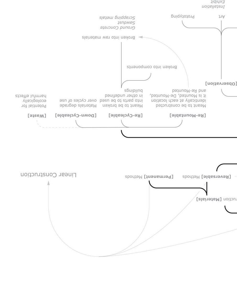
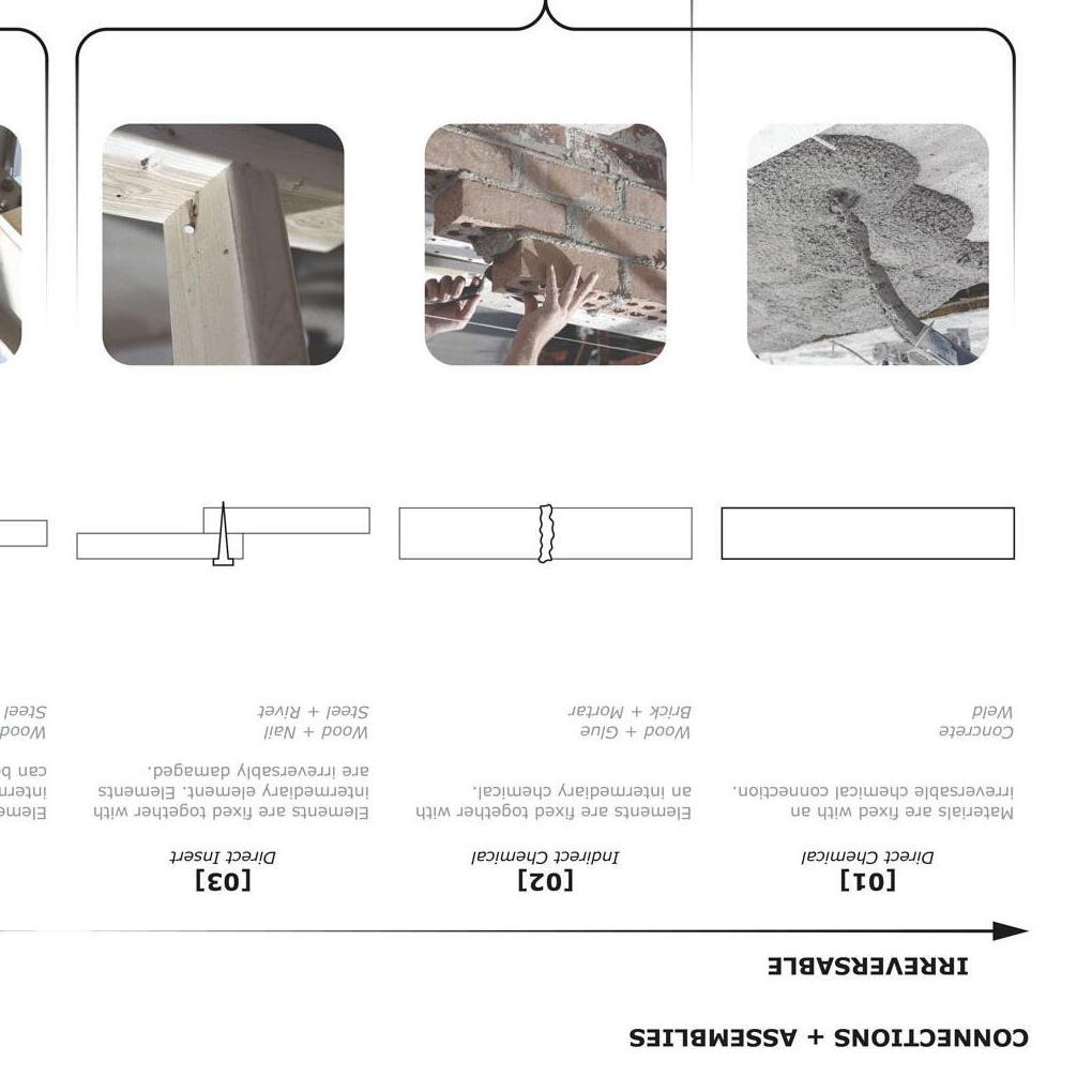
Circular construction should be present in all parts of a building’s lifespan, from material supply to eventual waste, where materials and elements are recycled and reused throughout. These methods must also be utilized at the scale of connection details and within the process of recycling materials. The presence of irreversible chemical connections, however, creates a contradiction regarding the ecological performance of an individual building and the amount of circular construction utilized. The ecological performance standards of the construction industry can be successfully met with passive techniques and differing levels of complexity in demountability.
SINGLE AXIAL BIAS →

The single axis proposal is expressed on the site as tower or island extrusions. These points of extrusion act as the basis for a permanent vertical conviction that has its own horizontal systems implemented within the structure. The degree of permanence on the site radiates from each of these tower or island extrusions which are separated by factors such as program and modularity. each of the islands independently operate, allowing for change on one island without affecting the other, thus promoting modularity in the structures. It also allows for nearly all of the secondary horizontal structure to be impermanent and flexible.
← DOUBLE AXIAL BIAS
The double axis proposal is expressed as a wall extruded from a single line that provides a vertical framework that can also extend its permanence across a single horizontal axis. All vertical convictions are held within lines and become forms such as walls and chases, while the horizontal convictions radiate out from these structures. These same linear forms act as the permanence on the site.
TRIPLE AXIAL BIAS →
The triple axis proposal represents an extruded plane that is expressed as a field or grid-based, redundant foundation. This grid extends to all sides of the building while providing vertical convictions as needed. The redundancy of the foundation gives it tremendous strength allowing for the removable structure above to remain nimble, flexible, and easily demountable to the point that the program itself can be entirely adaptable.
11
Circular construction is possible through a circular economic model. This means most of what impacts circular construction feasability is often adjacent to architecture and its representation is not through drawing but rather diagramming.
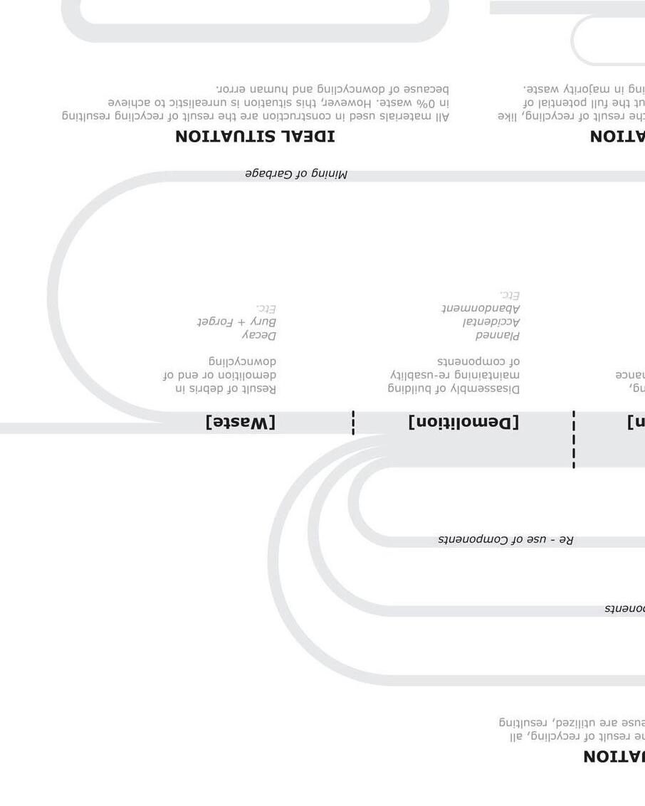
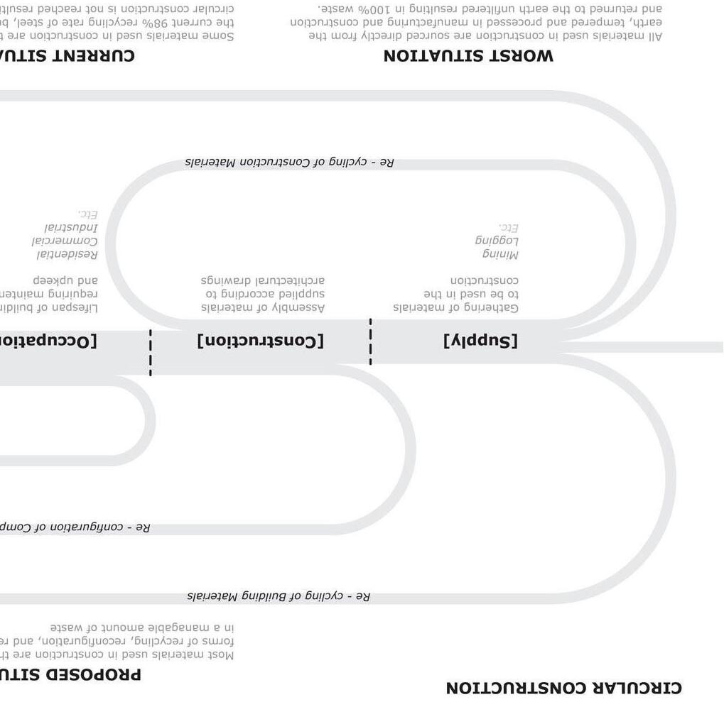
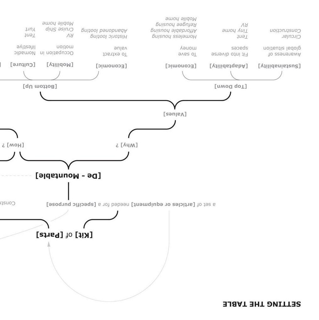
WHY IS IT ? ↑ / WHAT IS IT ? →


All architecture is de-mountable as it is eventually demolished or abandoned. All architecture is also made from a kit of parts which are prescribed by architects with instructions on how make them whole. De-mountability implies re-mountablity. This dichotomy is the essence of circular construction which requires energy that is only exerted when its outcome has value. Therefore, the kits of parts and their subsequent instructions that architects prescribe should be in service of re-mountability which can exist within the current set of economic and cultural values. Some outcomes of circular construction have value which is not immediately obvious. Circular construction which is beneficial to the environment is a much larger and longer idea whose benefits are not always clear to those who are short-sighted or ignorant. The eagerness to replace and demolish architecture for new lies partly in the excitement of experiencing a new building and partly in
the cost of demolition. In some sense, the power of architecture and the experiences it creates is like a gift which you cannot unwrap quick enough. However, the true driving force of quick demolition is to be efficient and keep labor costs down. (Would we waste so much wrapping paper on Christmas if we carefully removed the tape and unfolded the paper without tearing it for reuse? Is a circular Christmas possible?) A careful demolition ensures proper recycling techniques where materials remain virgin and, dependent on the material, reusable.
12
HOW IS IT ? ↑ / CITY OF CROSSWELL, MI →


Irreversible manufacturing and construction techniques prevent certain architecture from being disassembled and in most cases, render materials un-recyclable. These techniques are often chemical, and in service of building performance. While the welded steel joints perform better than the reversable bolted joint, they can at least be melted down and re-used, as 98% of American steel does. To give the current construction industry credit, steel is a beacon of recycling and reuse. Other chemically bonded and treated materials are not as lucky, as their chemical transformation not only prevents disassembly, but prevents reusability if broken down into their raw materials. In some sense, the ecological performance of an individual building is at odds with the ecological performance of the construction industry. It is then imperative that these performative aspects of a building are cherished for more than just their performance, and that rather than
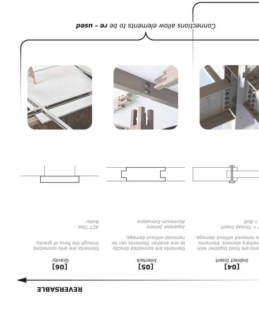
breaking them down and reusing them as raw materials like recyclable materials (which is not possible), they are reused as a complete assembly and constructed to be as easily removable and reusable as possible. In lieu of an economic revolution, it is the architect’s responsibility to strive towards a circular construction by defining how far materials can break down and still be usable, and develop techniques and assemblies to ensure their future usefulness.
13
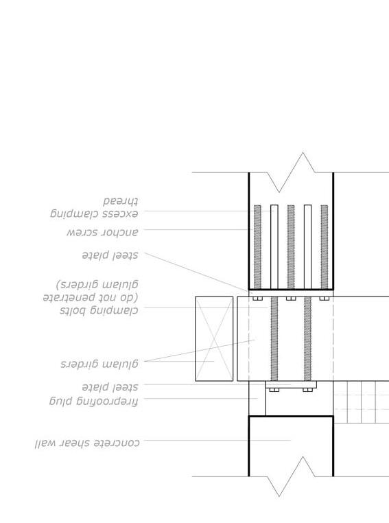
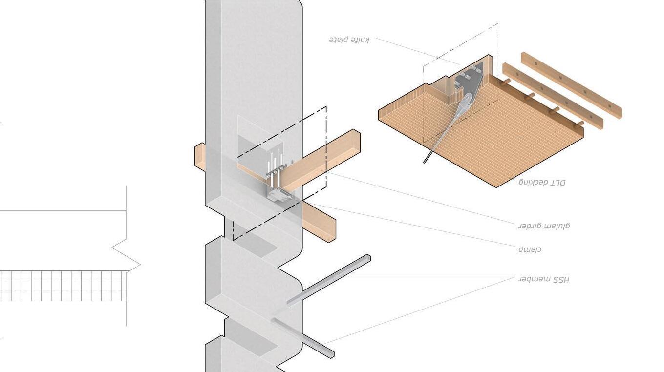
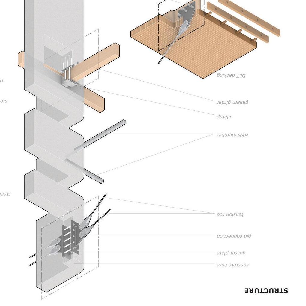
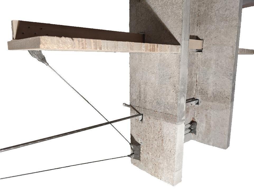
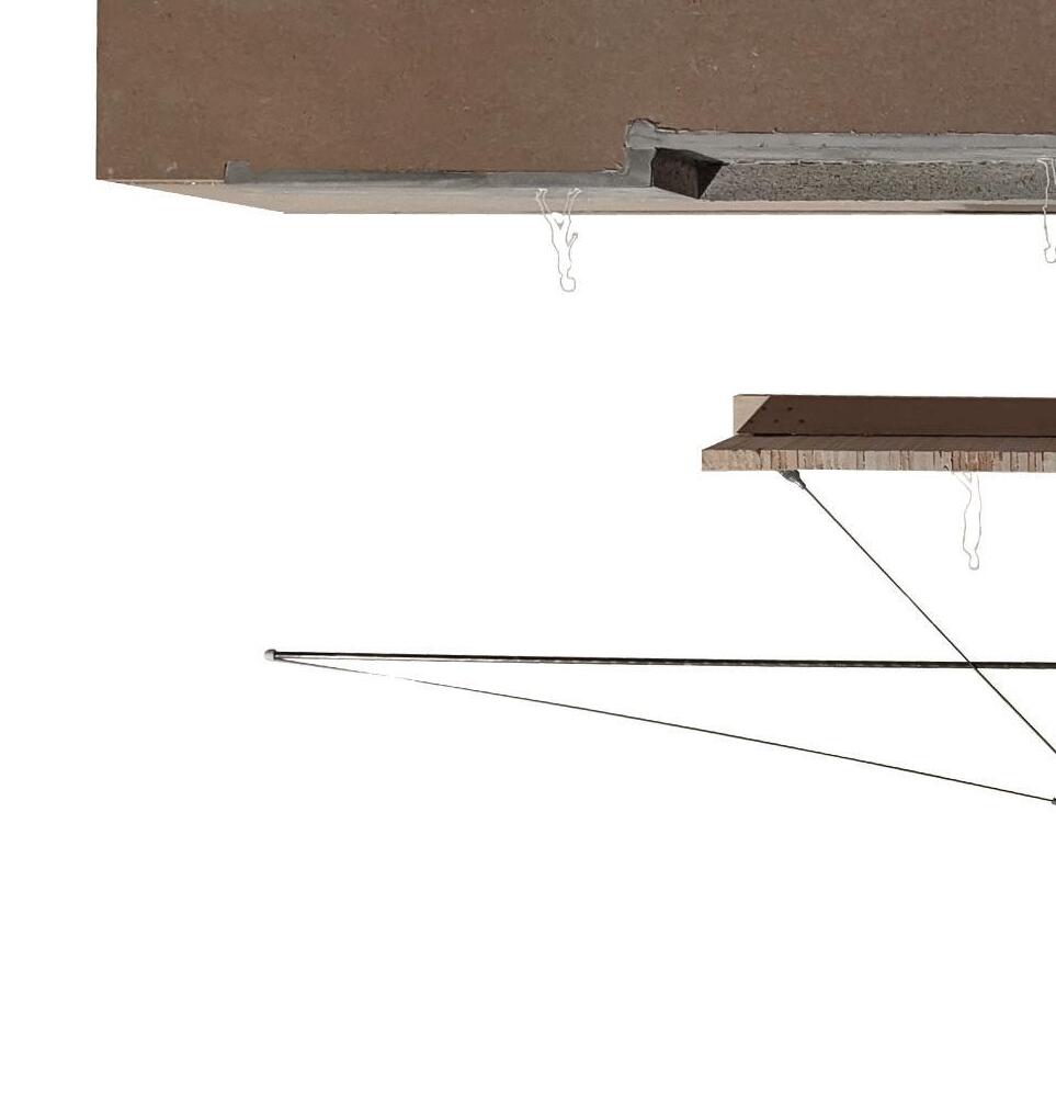
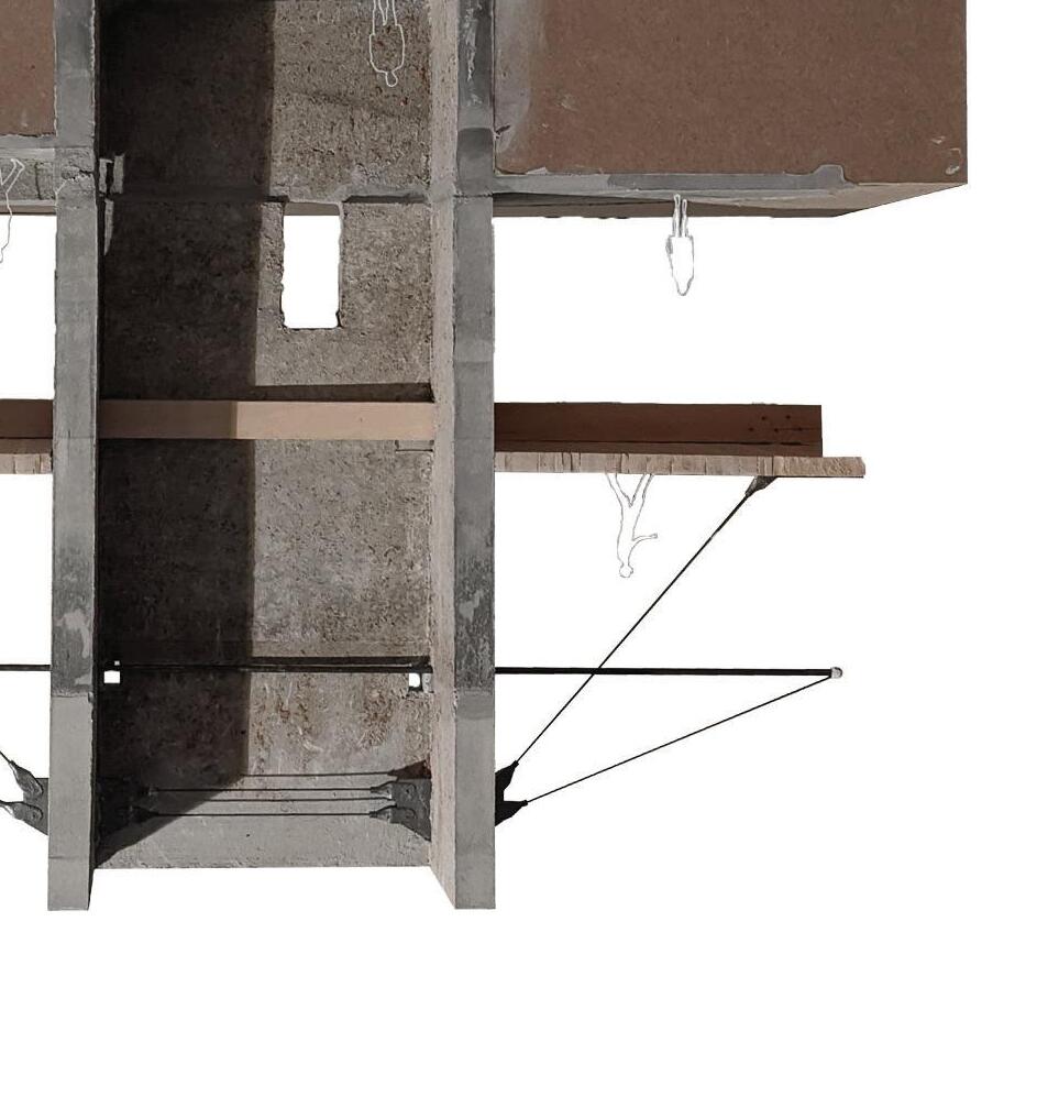
← STRUCTURAL DETAIL / CORE DETAIL ↑


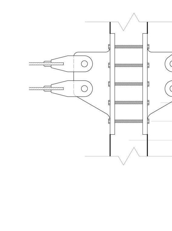
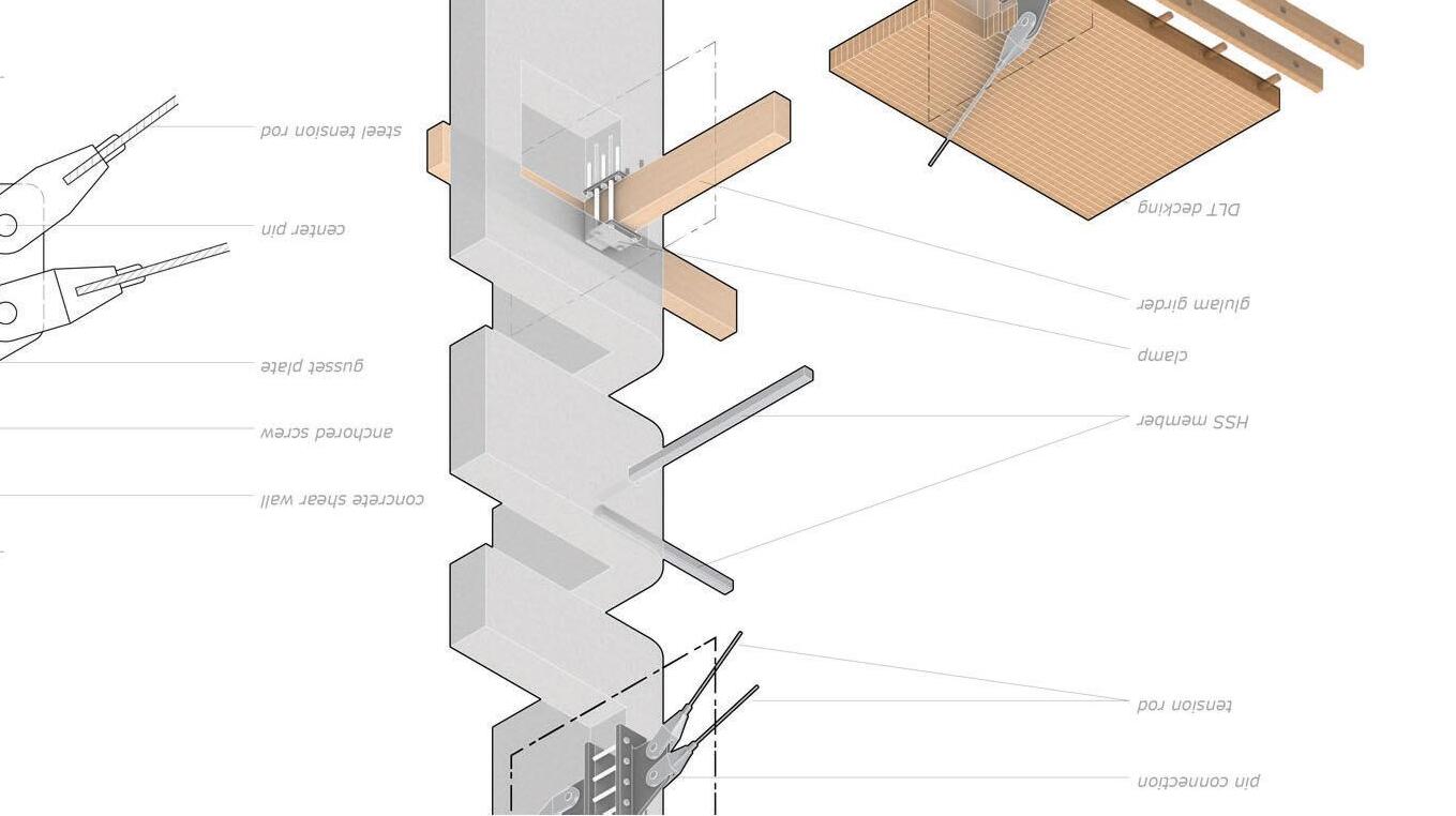

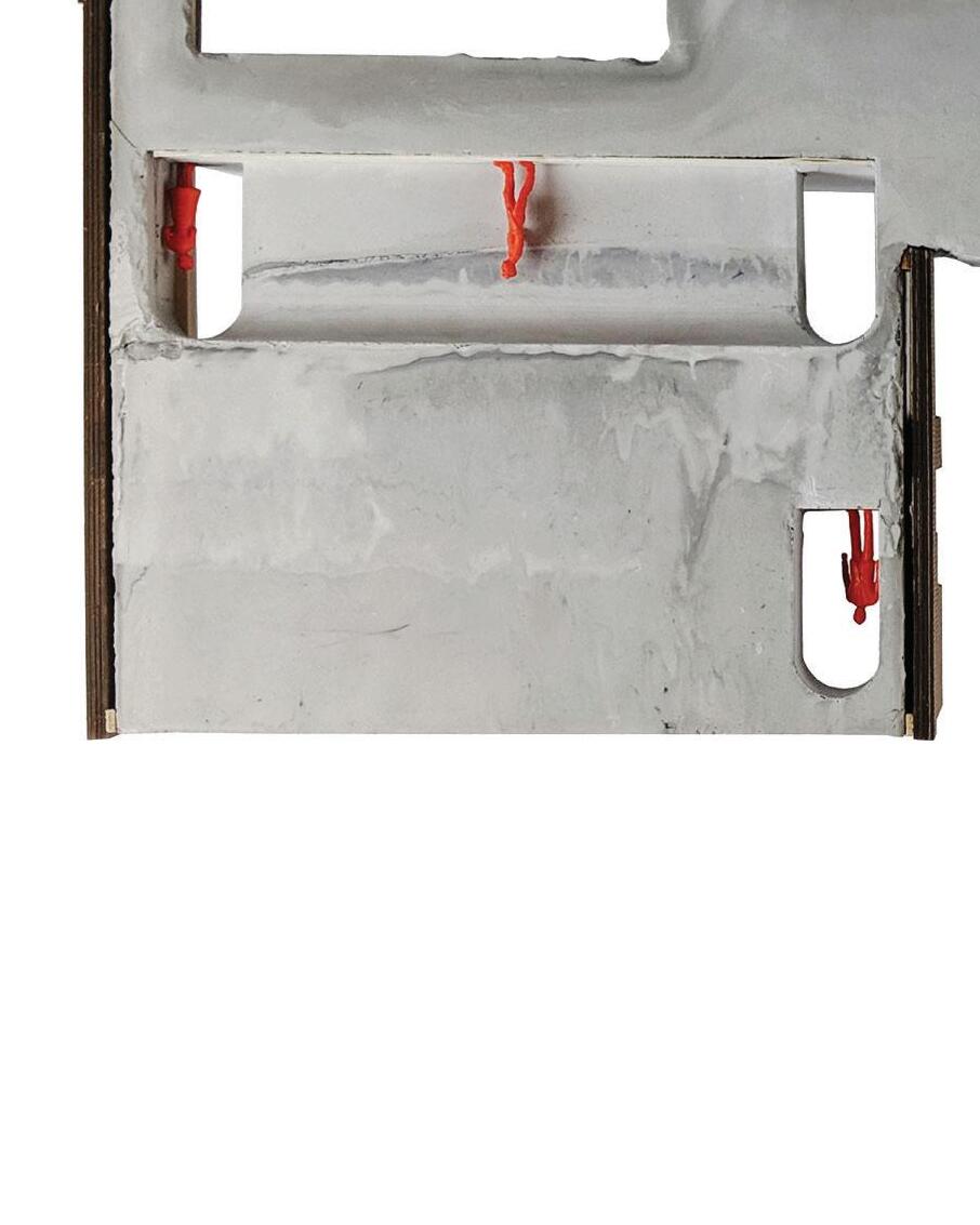
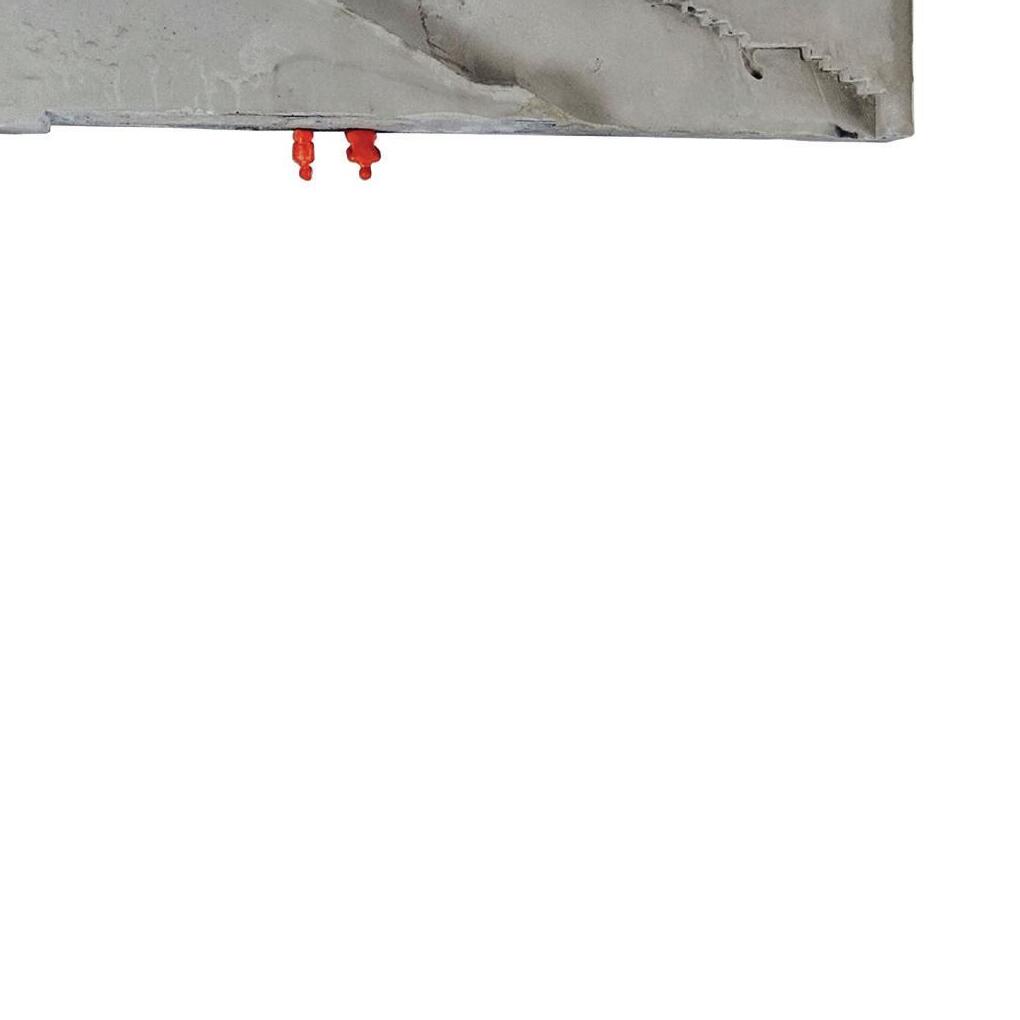
The core of the building is its most permanant gesture, and hosts all of the major systems, acting as an anchoring point for mechanical, structural, and circulation systems. It is constructed out of concrete and is meant to be a useful remainder after the building is occupied and the site is reconfigured.
14
Although this project took place in the depths of the COVID-19 Pandemic, and a model was not a studio requirement. The semesters before similarly had no physical deliverables and this built up an eagerness to build.
Starting over Thanksgiving, I transformed my parents garage into a model building studio fit with heaters as winter began. This model was one last hurrah to model building during my undergraduate studies.
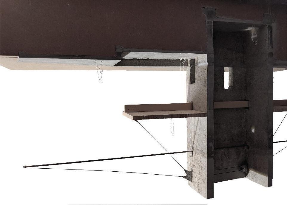
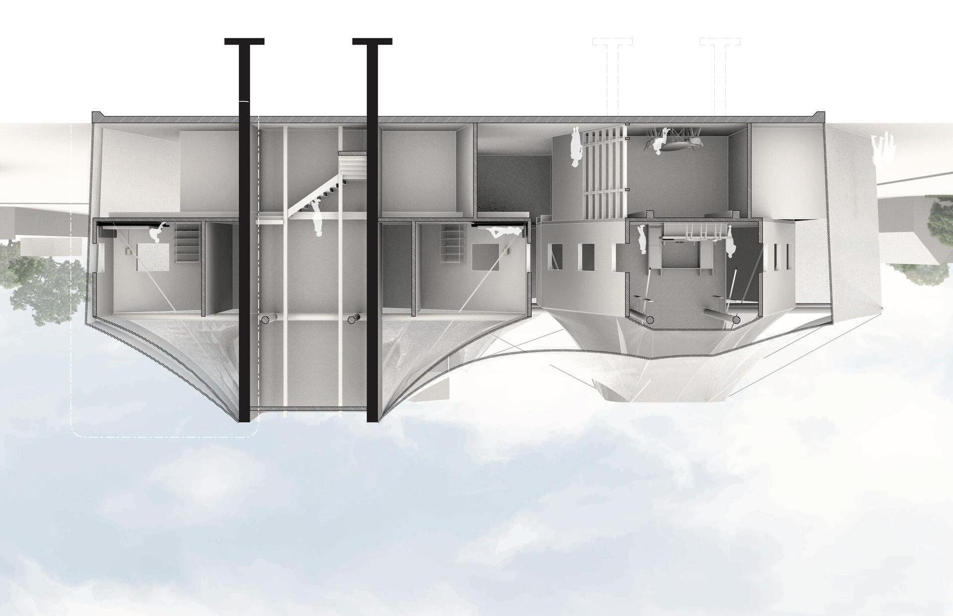
← BIG MODEL / PERSPECTIVE SECTION ↑
The unique composition of architectural systems can best be seen in together cohesively in section, where the gradient of permanance radiates from the core, with its systems fanning out, most dramatically being the suspended cantelever of the second floor. The model reflects these systems and materials at an equally dramatic 1/4” = 1’-0” scale.
15
The title of this work is much broader than the project itself. As one of the first architecture studios, the assumption was made that the building would exist ‘off the grid’ and we would only contend with natural forces.
We were encouraged to work physically. Making formwork and casting with plaster or rockite captured what could not be digitally and the photography of the model existed as the sole representation of the project.
PHENOMENOLOGY


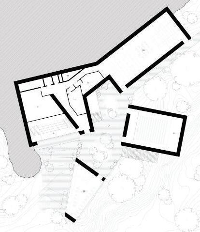
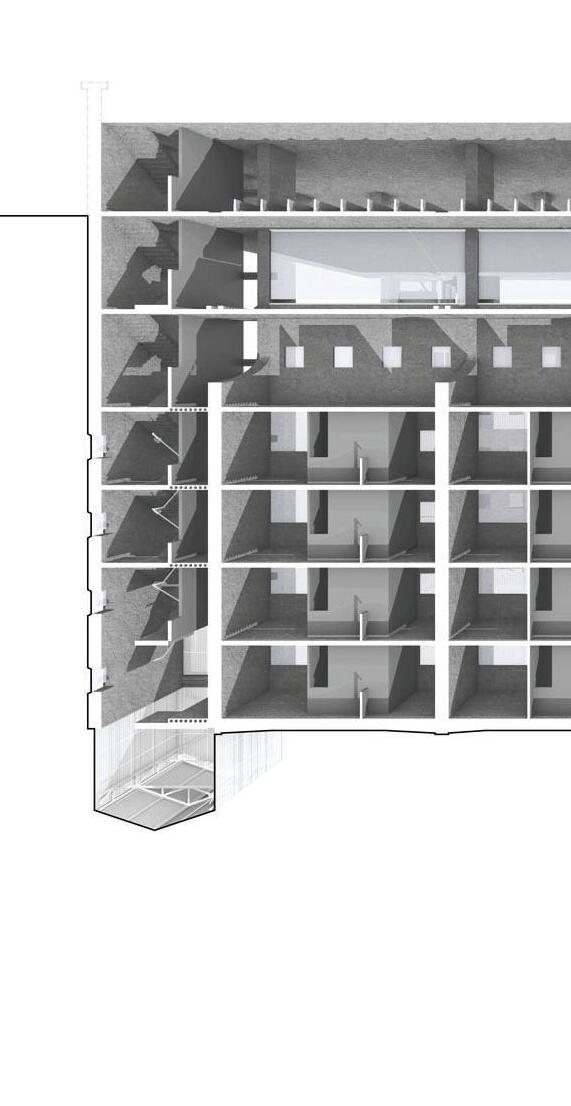
This Project is composed around a unique site, taking advantage the nearby water fall and outward views. Inside are two theater spaces, one audio, one visual. The visual theater is accompanied by a secondary audio experience which is the sound of the water fall, amplified by a truncated square. In contrast, the audio theater is accompanied by a natural light, brought in by a large light well that extends from the top of the building to the lowest floor. These two theaters are connected, divided, and organized by a monumental concrete wall. This wall reflects sound, diffuses light, and encases all major circulation routes. These encased routes creates a distiguished processional walk between each space, as to make sure each sensory experience doesn’t bleed into one another.
← FINAL MODEL / SEQUENTIAL DIAGRAM ↑
A cut through the monumental wall, exposing the interior circulation routes, and its various entrances and exits. These lead into and out of the theaters, the first that spans from the first to second level, and the second that spans from the second to third level.
 Integrated Design 2 - 2019 - Prof. Jim Stevens
01 03 02 04
16
← FINAL MODEL / STUDY MODEL ↑


Both theaters are exposed and occupied. The final model represents the culmination of many study models experimenting with thin planes intersecting or penetrating a monumental wall.
01 0 03 3 0 02 2 0 04 17
SECTION MODEL ↑
A cut through the monumental wall, exposing the interior circulation routes, and its various entrances and exits. These lead into and out of the theaters, the first that spans from the first to second level, and the second that spans from the second to third level.
A key transition in the model making process was the introduction of ‘Rockite’. A concrete looking, plaster acting mixture that renders the materials it is casted against.
Early study models used a basic plaster of paris, and were cast against tin foil, cork board, and acrylic. Final models were cast using rockite against balsa wood.
18
This studio was taken simultaneously with the technical courses offered at Lawrence Tech, and the focus on detail and tectonics is reflected in this work.
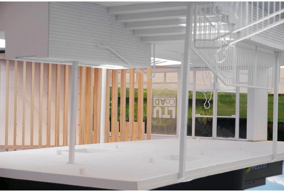
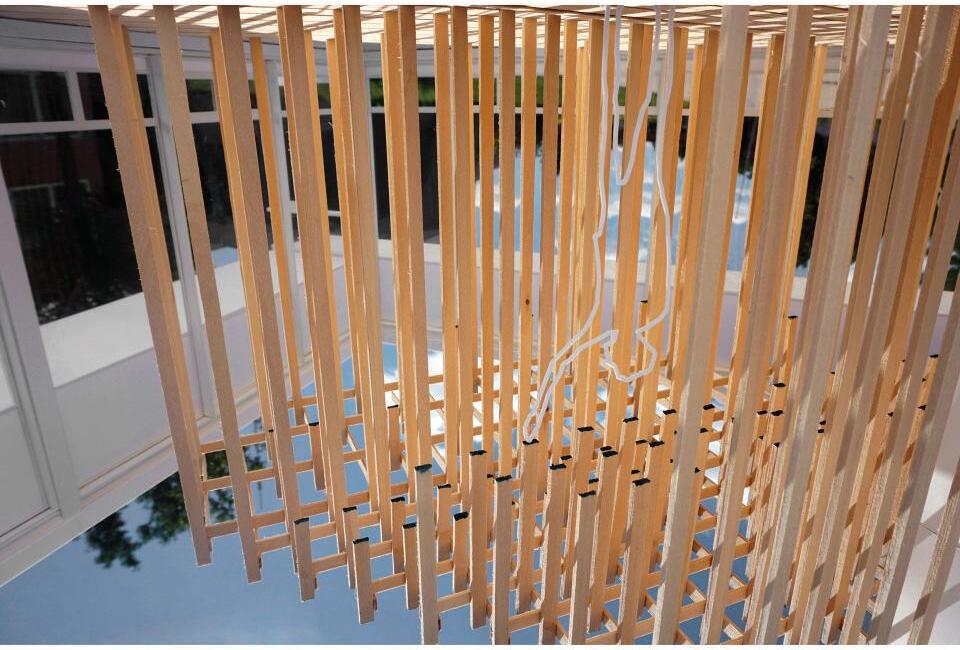
ASSEMBLY
This project is a system based approach to architecture, which includes structure, enclosure, and energy. These systems and their relationships with eachother and the sites context guided the majority of the design decisions. These technical and measured decisions were made in pursuit of an immesurable phenomenological space.
← SYSTEM MODEL / SEQUENTIAL ASSEMBLY ↑


The morphology of the project optimizes the spanning capabilities of double tee slabs and bearing walls. Light is introduced to the space by pushing and pulling walls and slabs to create windows and monitors. Walls pushed out are double tee bearing walls, and walls pushed in are custom cast solid walls. The light is further manipulated by the stems of the double tees, acting as vertical fins on the east and west facades, While the form of the custom cast solid walls distribute light into the space.
Integrated Design 3 - 2019 - Prof. Daniel Faoro
0 1 03 02 04
19
PERSPECTIVE SECTION ↑
The building’s program is split into three parts, which is reflected in the building’s form. The north section is main assembly space, where the wall panels are pushed in far enough to accomodate a hallway. The south is vertically split into 3 levels of ‘back of house’ space, and the wall panel offset is there to allow light in. The center is also split into 3 levels and is pinched. The top of the pinch is an open to sky gathering space, where the bottom is the lobby. This pinch identifies the entrance to the building as well as a direct connection to the sculpture garden behind.
The studio was split into the layers of construction systems. It began with development of structural morphology, the enclosure of the structure, and finally energy systems.
20
SYSTEM MODEL ↑
The model is meant to act as a clear and readble expression of the structure and enclosure. The sturcture sits on a clear base, allowing for a view of the interior conditions. The double facade enclosure sits on the vertical double tee fins and remains removable to demonstrate the sequence of assembly.
0 1 02 03
21
Lawrence Tech brought in a professional photographer and these photos reflect that decision.
ACROSS WOODWARD AVE. / INSIDE ASSEMBLY SPACE →
By pushing and pulling the wall panels, an inbetween space is created. This slippage allows light into the space, and the interior wall panel profile distributes this light further. The inbetween space provides a circulation route, and secondary space for the main event space. Within the render shown, the interior most space, inbetween space, and exterior to Woodward Ave. can all be seen.
↑
22
I had just moved to Detroit after graduation and was in need of furniture. This table was made out of neccesity and is the desk I am currently making this portfolio on.

I plan to carry it out just as I carried it in to accompany me in a new home.


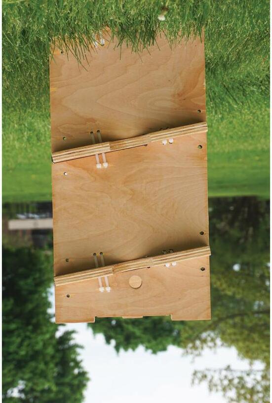
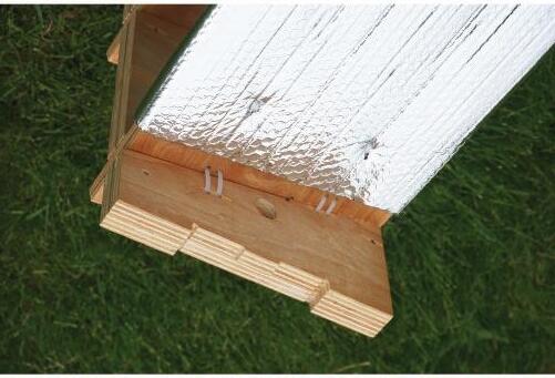
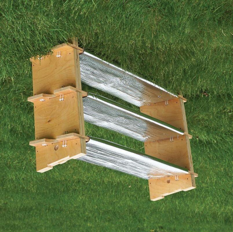
STRAP TABLE
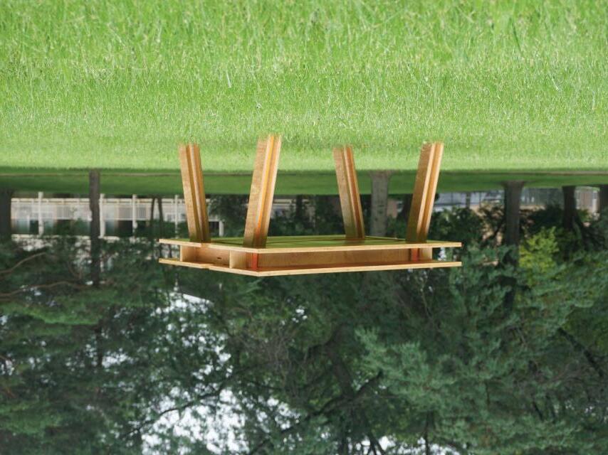
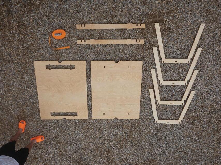
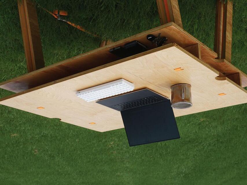
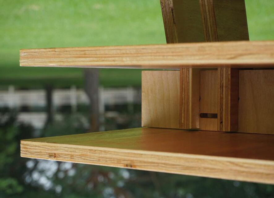
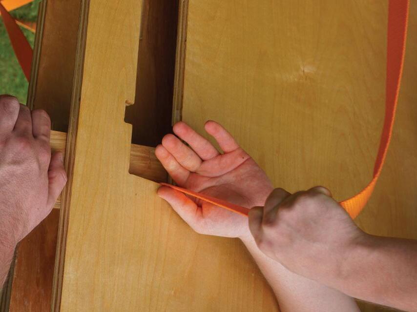
The Strap Table is made for working, dining, entertaining and moving. The table is made to move with a nomadic and uncertain lifestyle and remain useful. The table is friction fit and can be disassembled, packed flat, carried, and reassembled. The table is held together by a continuous ratchet strap which is used as a shoulder strap when moving making all parts of the table useful all of the time.
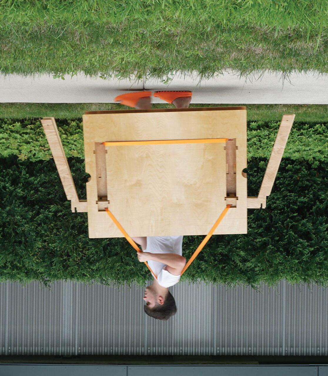 2021 - w/ makeLab
03 3 0 05 0 5 02 2 0 04 0 4 6 06
23
APPENDIX A - MODEL + OBJECT


2018-2022 ↑ crit prax - 2019 ↑ MOMA house - 2019
↑ Maison du Pueple, Clichy - 2022
24
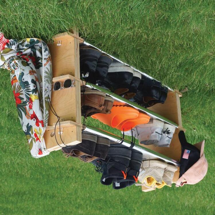
↓ Shoe Shelf - 2022
APPENDIX B - DRAWING
2017-2023 ↑ Sheldon
- 2019 ↑
↑ places of memory - 2022 ↑
↑ postcard futures - 2023 25
Museum
Civic Imaginary - 2022
Affleck House - 2017
