

All the iron is only the edge of those people.
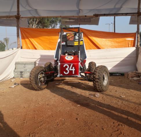
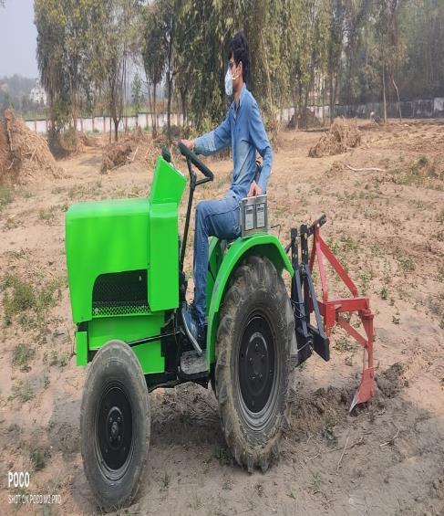
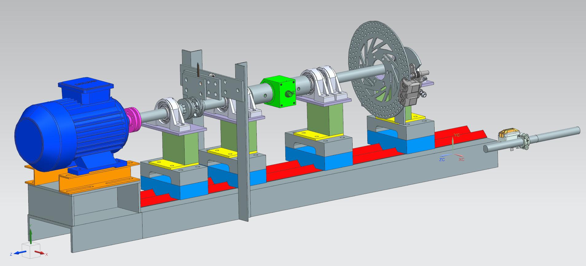
The test-rig was developed to test the dog-clutch having a modified teeth profile. The project of development of E-tractor led to significant challenges in terms of electrical system, including electrical motor that unable to deliver the power on the old tractor chassis. The project idea was risen when difficulty was observed in the losses in power transmission at wheels. It confirmed that the sliding mesh transmission won’t work and the quick shift is necessary especially when pulling heavy load or while farming. The solution was to develop the constant mesh transmission and replace it on the same casing. According to the motor specification and weight of the vehicle, designed the dog-clutch with the modified profile and developed the testrig to verify the results with different torque application.
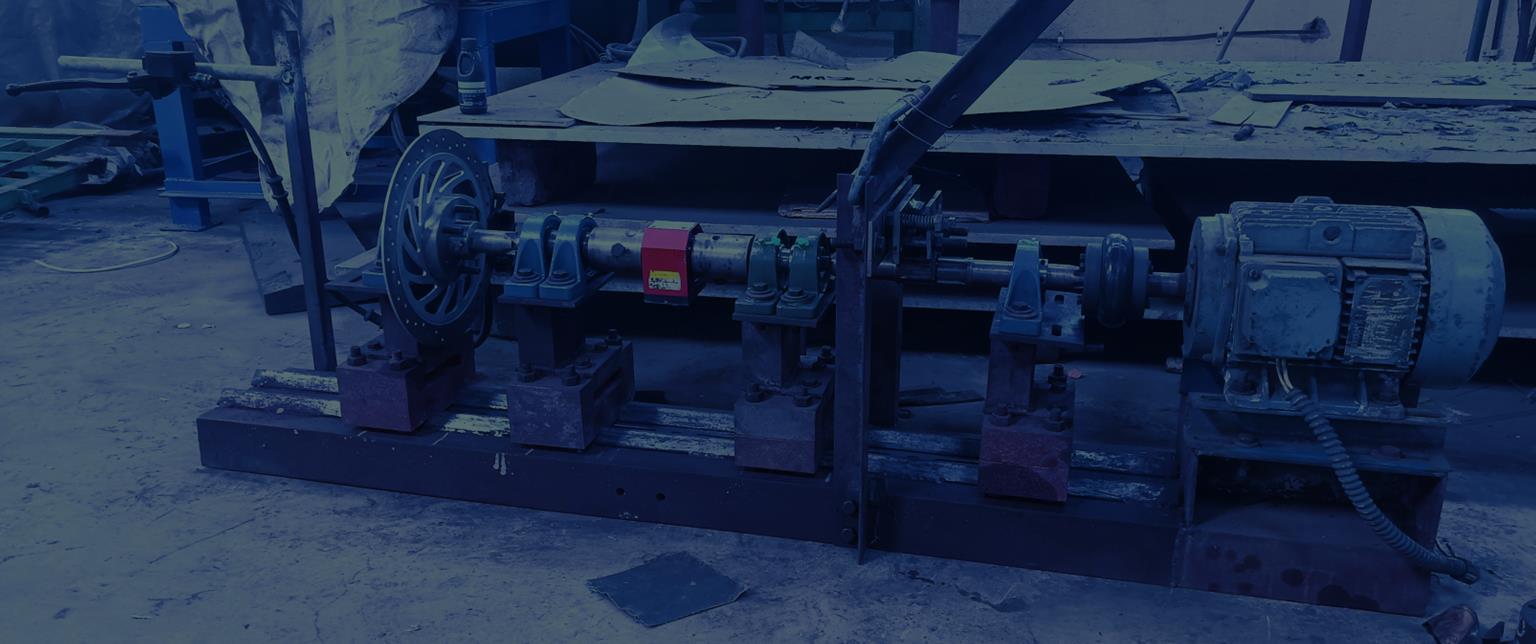
The manufacturing of test rig begin with its base, various parts gone through different conventional machine to achieve the required tolerance and surface finish.
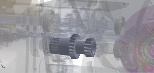
The clutch on the other hand was manufactured in five-axis CNC m/c (DMG Mori)
The base structure is a key for any test-rig, similar to the machine tools as there damping ability provides excellent workability upto the precision. The property of cast iron enhances the stability during the various operations.
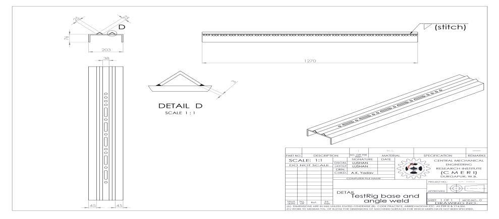
To make the test-rig compact, the C-section made of die steels was used having similar properties to the cast iron, hence named as the test rig base.
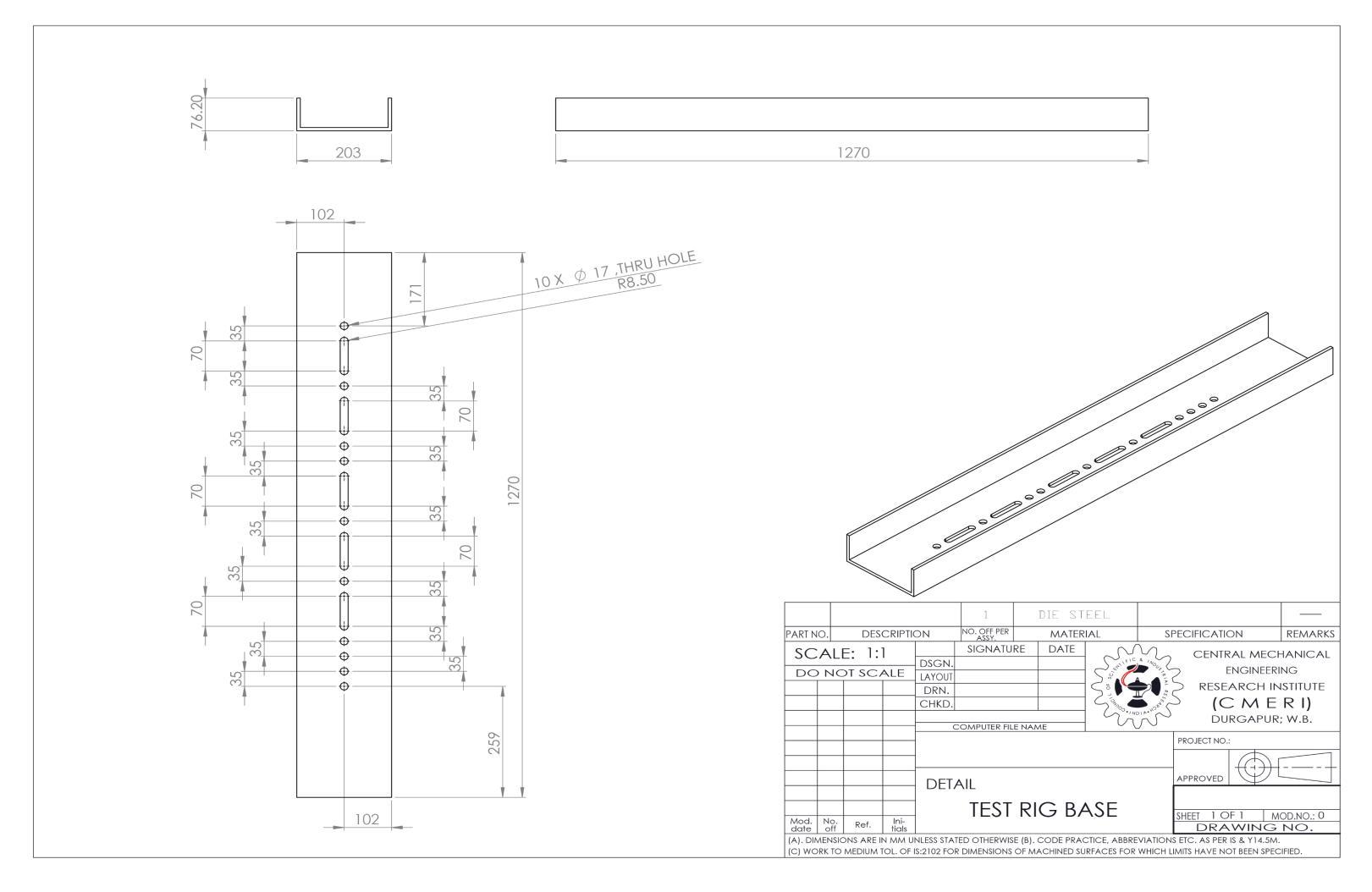
Making the base ready was the key objective to have the foundation for the project. The whole assembly was prepared on the siemens NX software and analysed and finalised the dimensions.
The operations were drafted accordingly, by drilling the holes of the specified size and spacing between them.
The angle rods were welded to act as the guide for the base carrier to make the adjustments for to and forth which provides flexibility perform the tests having different length of shafts or the diameter. It can be also used for the different kind of test like torsion.
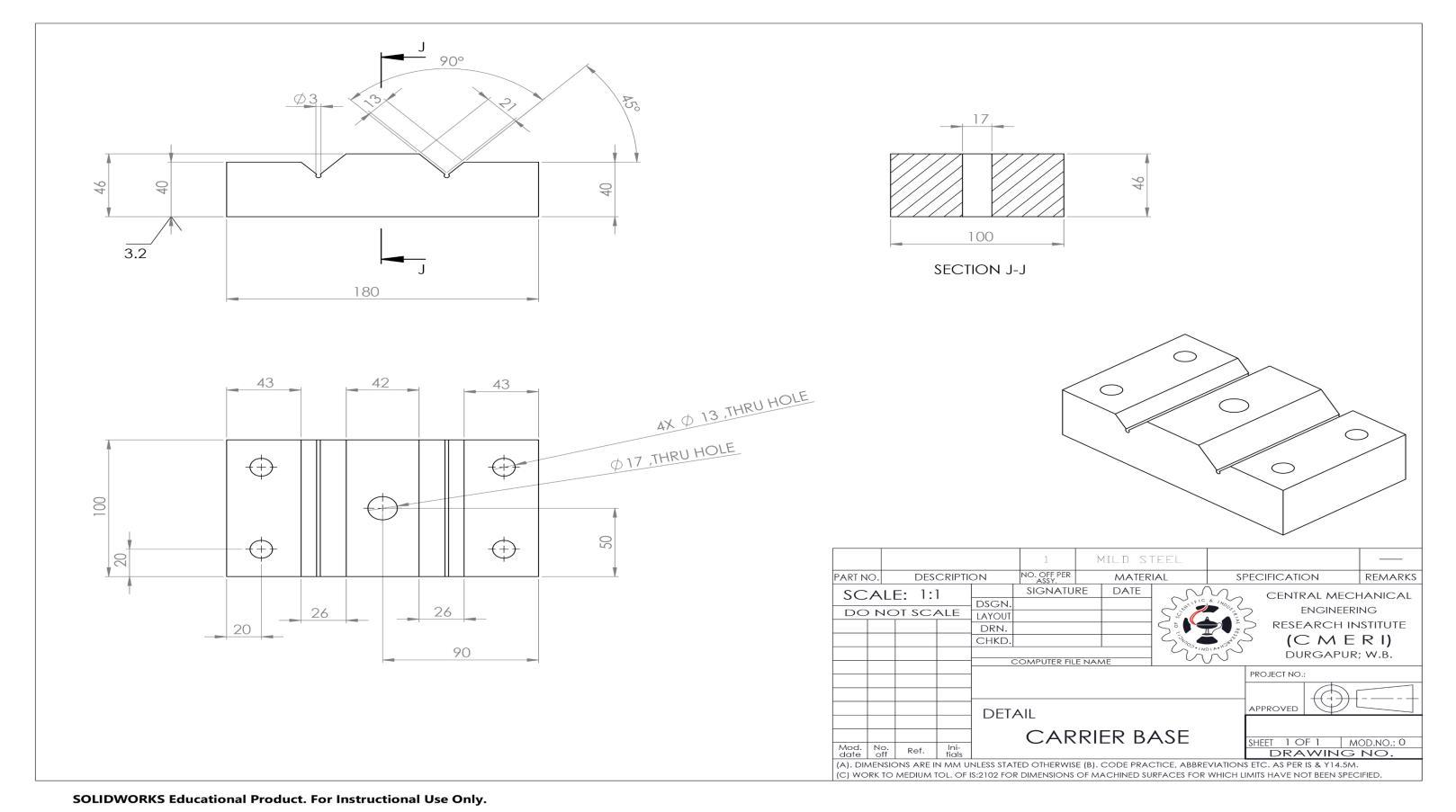
Base carrier and bearing carriers are the to provide the structural rigidity and the damping effects during the test.
The base carrier is the lower most component which sits on the guide.
The V-shaped groove is machined by conventional vertical milling (VMC) machine by setting the work piece at an angle on the work.
The diameter of 3 mm at the notch is performed by the wire cut EDM machine.
Similarly, the part bearing carrier was achieved by VMC ( vertical milling centre) at all the sides along with the drilled through holes. The filler of the radius 10mm was provided by the ball nose milling cutter.
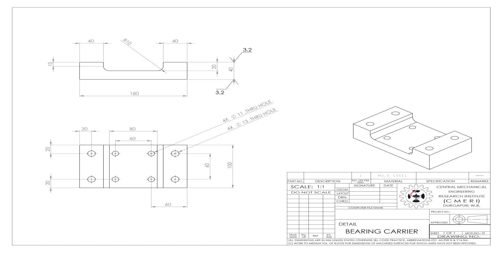
Overall, the surface finish was achieved by the surface mill to achieve the surface finish of 3.2 micrometers.
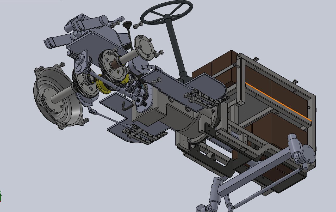
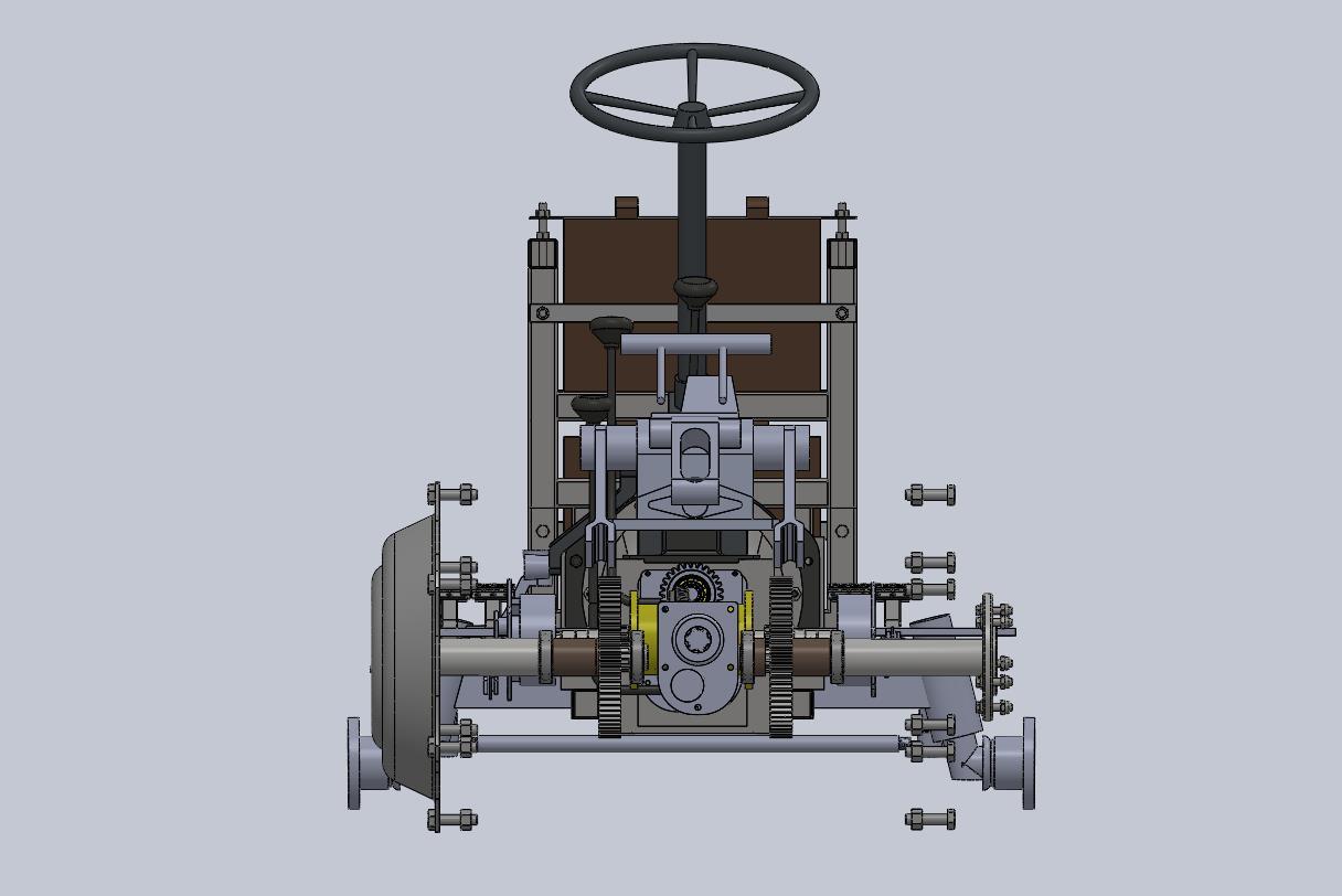
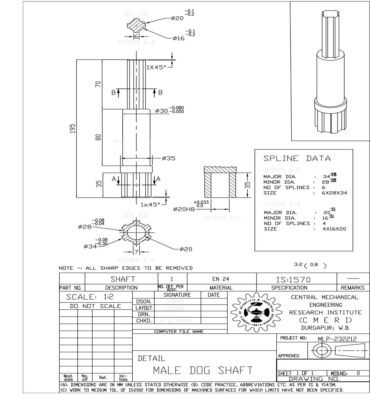
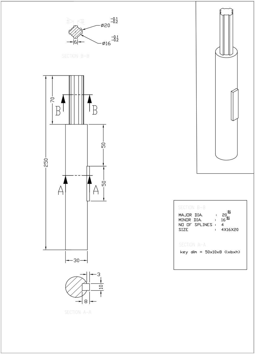
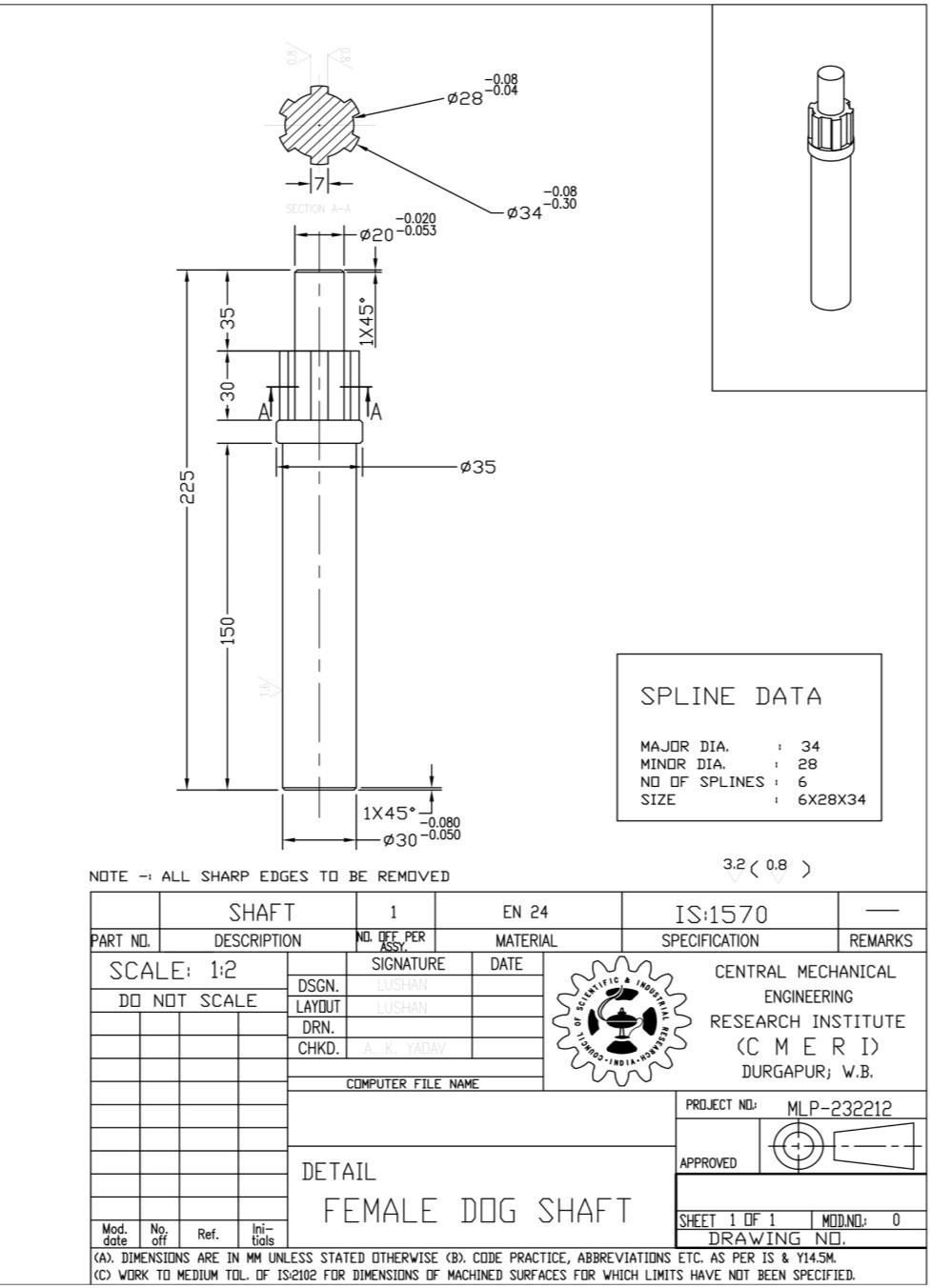
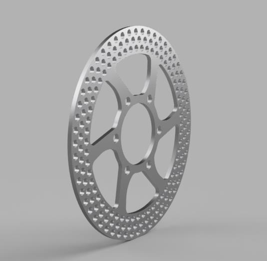
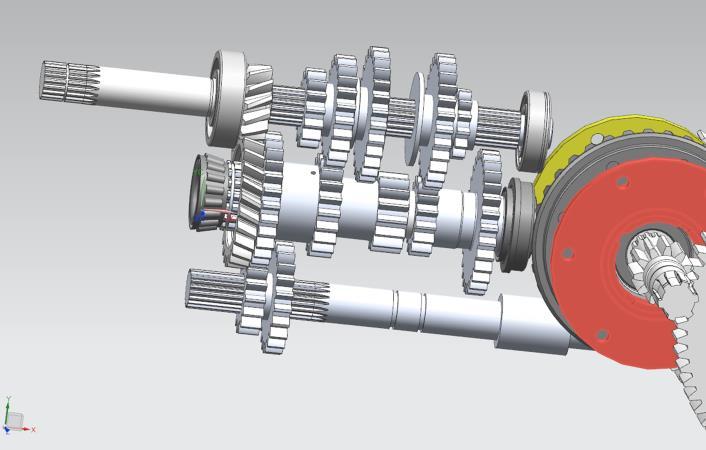
Shafts are the dynamic components to mimic the vehicle drivetrain in the testrig, all shaft are connected in series. The torque will be applied through the disc brake. The splines on the shaft and internal splines were decided on the basis of numerical calculations. The manufacturing of those splines were depended on the machine tool.
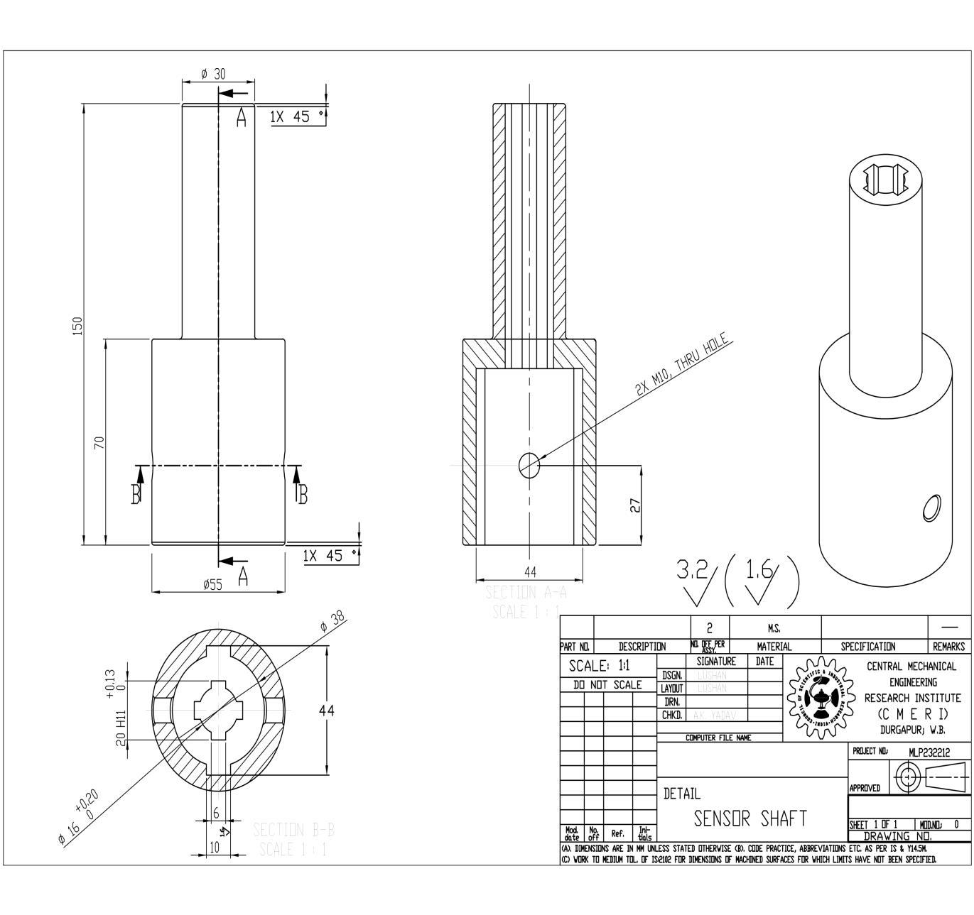
The internal splines were done on broach machine and the external splines on shaper. There is common diameter in all the shafts of 30 mm to be fitted on to the plummer block bearings.
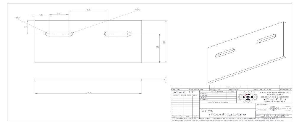
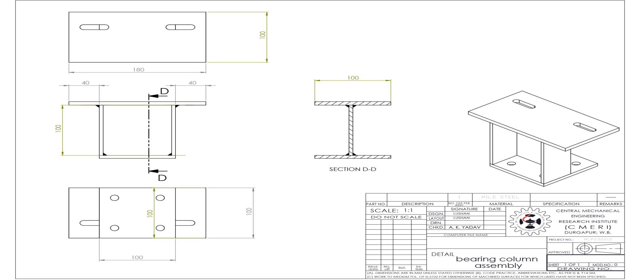
The plummer block bearings are to be rested on the rigid platform which should resist the torsional and axial forces. Hence the slab of 5 mm of thickness was enough to bear the loads on the small area and the torque generated by the electric motor. The bearing column assembly comprises C-section as the vertical column and is welded by the electric arc mounting plate and the base plate. The tolerance was achieved by the machine grinding treatment.
With the technical considerations and the consultation with technical staff the tooths of the clutch were designed and drafted. The detailed heat treatment tolerance was in the provision of the deformation and the dimensional changes after the heat treatment process (oil quenching).
All the conventional machining processes were performed before the heat treatment as the machine tools were not capable to machine the hardened materials due current tool specifications.
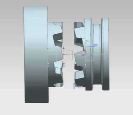
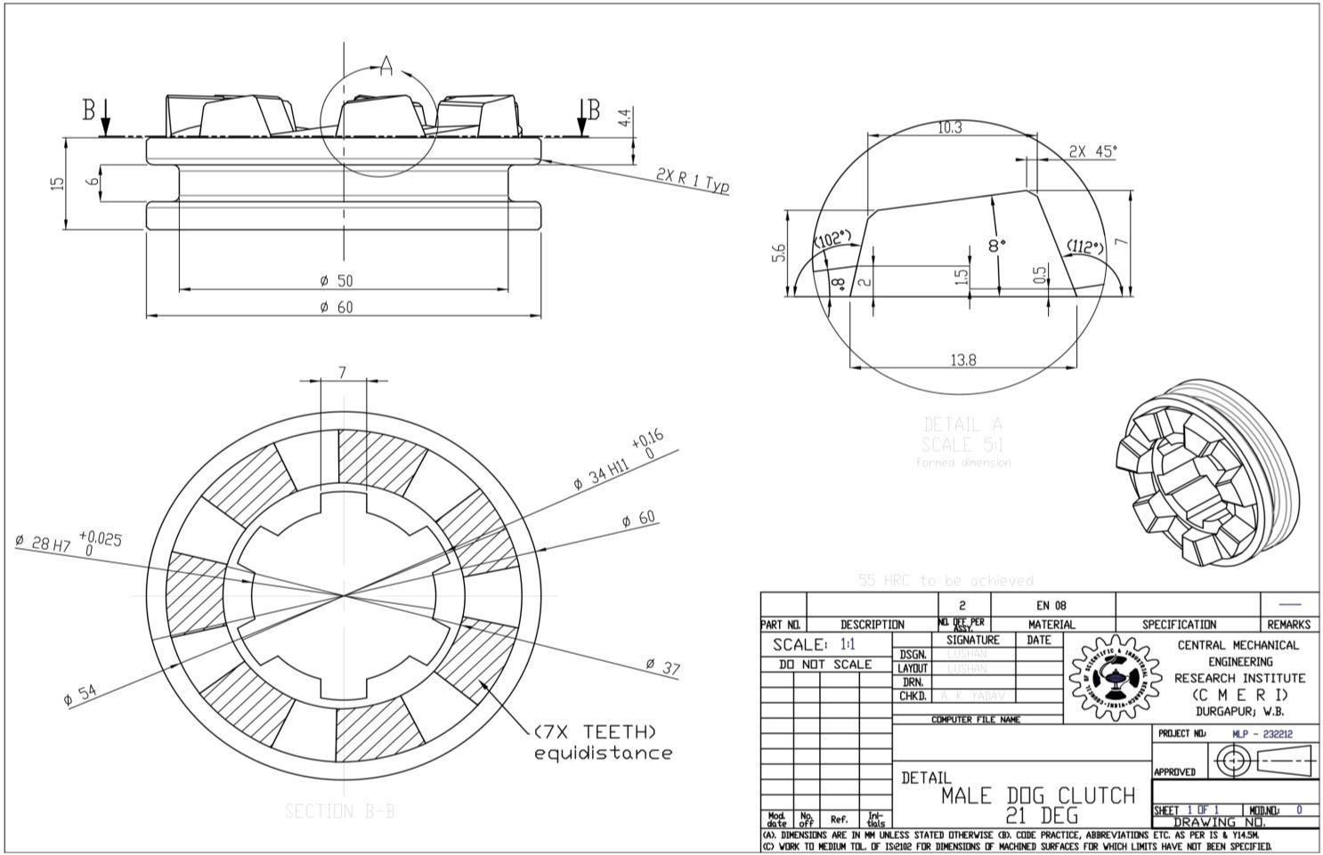
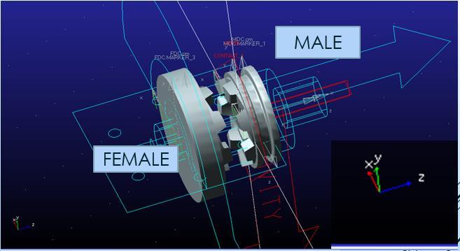
To analyse the behaviour between the simple dog clutch and trapezoidal dog clutch the iterations by decreasing the angle of one face were created in the 3d models and then imported to the MBD software.
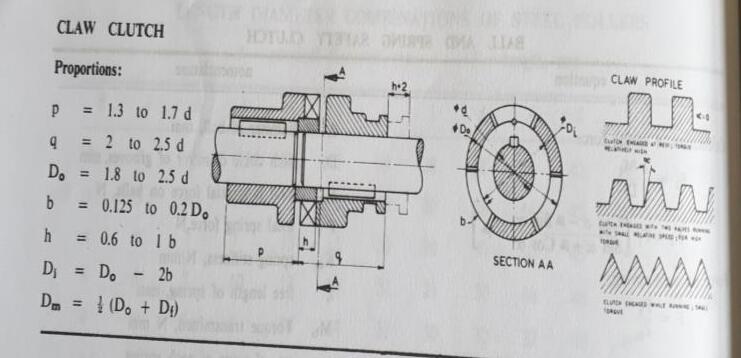
Literature of machine design from the “PSG Kalaikathir”
Ordinary differential equation → induces DOF Auxiliary equations → induces constraints
A mathematical model can be highly complex, and its relationship between inputs and outputs
A sensitive analysis is done to see how material stiffness, damping and coefficient of friction, affect the dog clutch engagement time in the simulation.
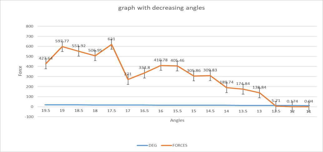
Iteration on the dog clutch was done To analyse the behaviour between the simple dog clutch and trapezoidal dog clutch the iterations by decreasing the angle of one face
The spline in the dog clutch was performed through the wirecut EDM.
The broaching option was excluded due to the treated material and tools are expensive as compared to the operation itself.
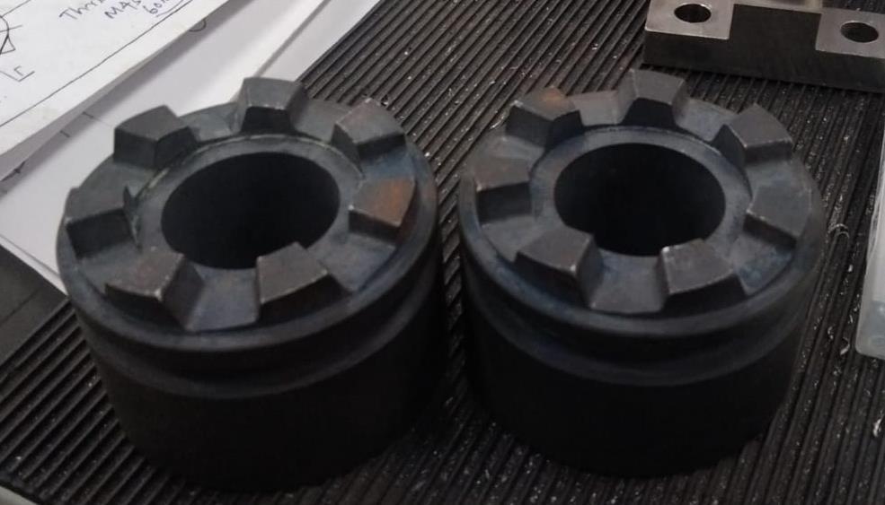
On heat treatment the hardness was achieved to 35 HRC which was enough for the operation. The old sliding mesh gears were near 32 HRC when performing the hardness test.
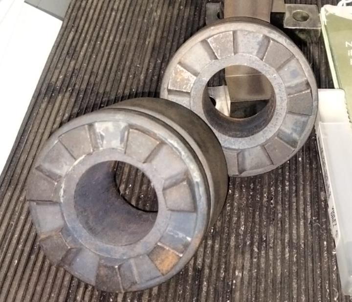
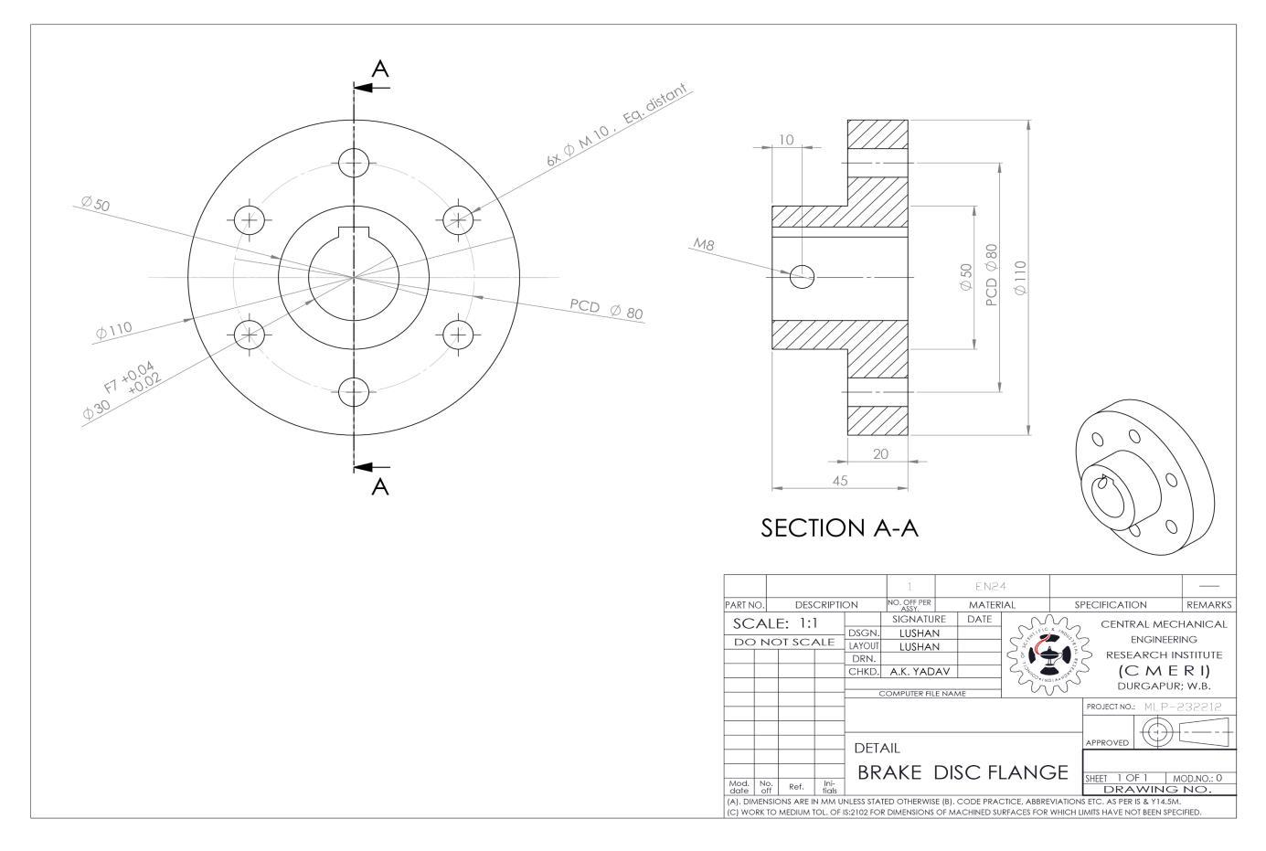
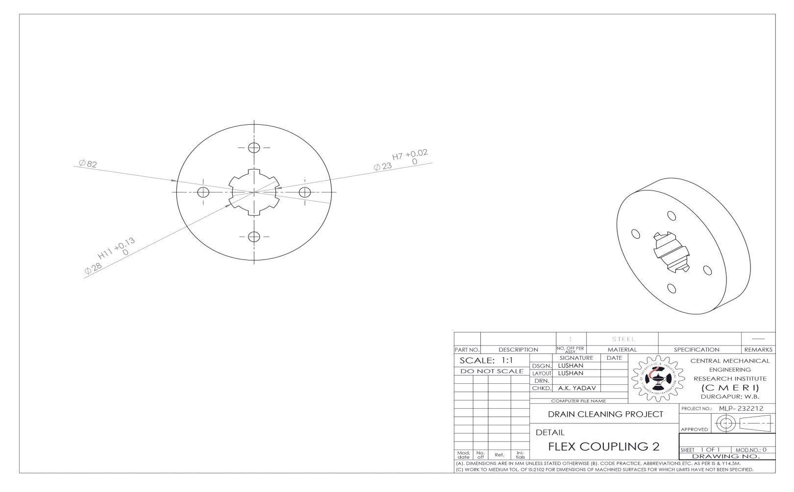
There is the need of standard components which can be used due to their trusted performance, reliability, compatibility and warranty. To make it performs well the ideal mounts are necessary. The flange was designed for the rotor disc to avoid any kind of wobble ( axial or lateral) during the operation.
The flange was provided with the internal key with standard for safety. The peripheral mount or pitch circle diameter of holes (PCD) was measured as accurately by the help of profile projector and confirmed by the inbuilt CMM ( coordinate measuring machine)
The flex coupling (T4) was dismantled and went through the wirecut (EDM) for mating with the shaft within the specified tolerances.
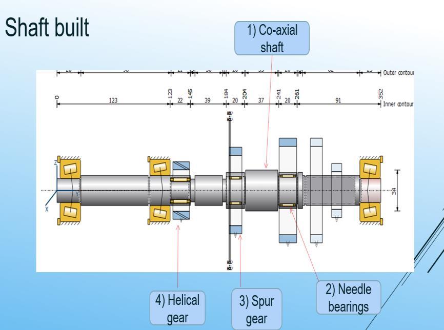
The shaft analysis begins with the some of the basic necessary elements like needle bearings, stepped shaft according to needle bearings, the gear locations, spline locations, locations of the co-axial shaft.
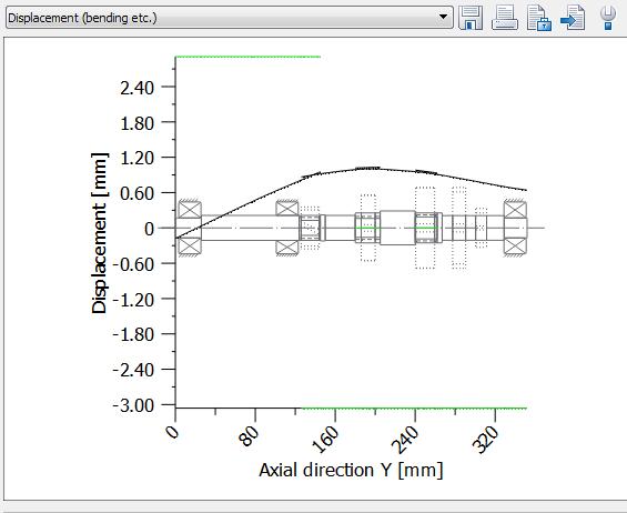
The torque of 85 N-m and the RPM of 1300 as at the input shaft.
Result comparison on with profile shift and without profile shift
A profile shift or addendum modification can be made to have an influence on tooth shape and tooth thickness. According AGMA 908 the factor is called addendum modification coefficient according AGMA 913 and newer ISO standards profile shift coefficient is used.
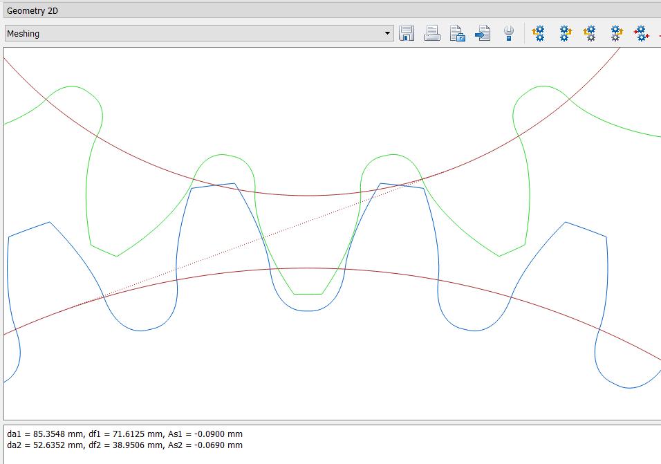
gear teeth may have modified addenda of 0.27 in order to avoid undercut, to balance the bending stresses in the pinion and gear, or to vary the relative amounts of approach and recess action This profile shift, as it is called in newer standards, is expressed in terms of a profile shift coefficient or an addendum modification
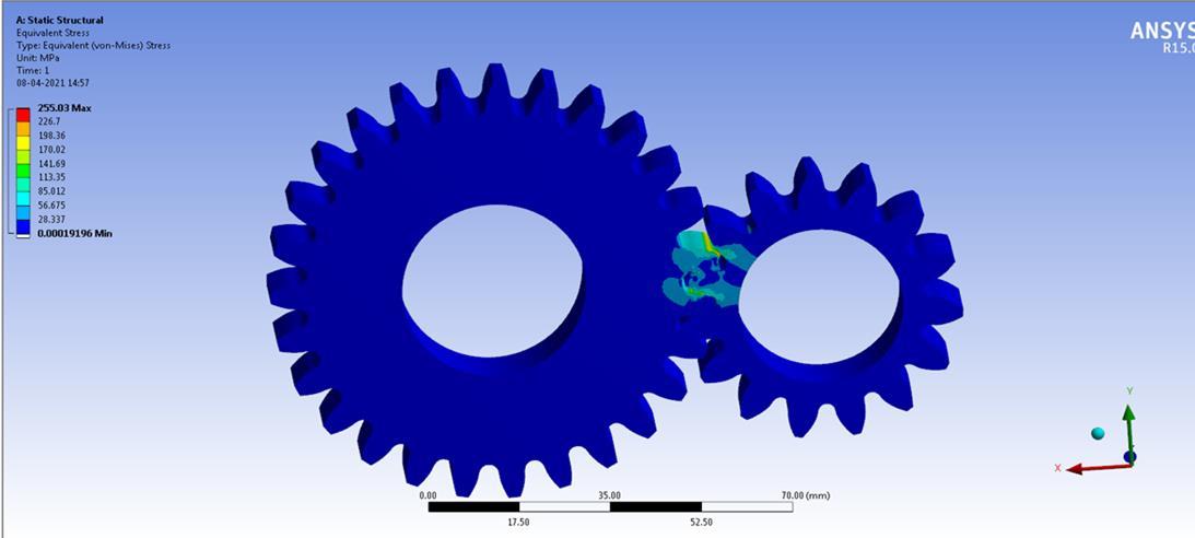
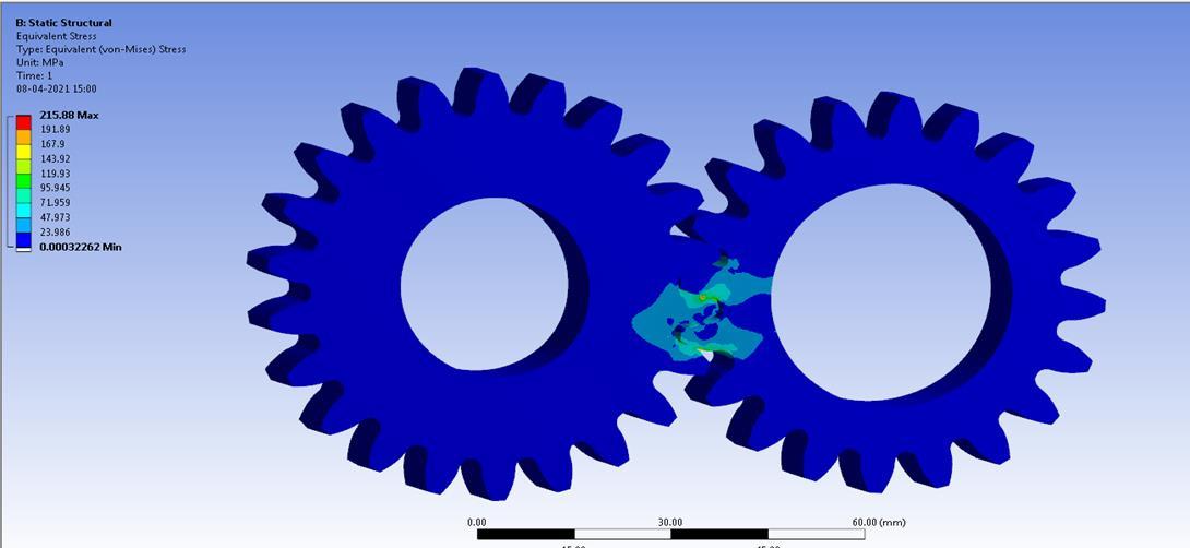
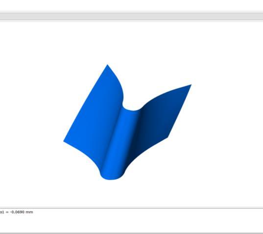
The analysis of the second gear that is analysed with the same torque as the analysis on the first gear.
The first gear analysis was done by considering the material (EN 24) and the heat treatment properties along with the tooth modifications, Furthermore, the earlier tests results from nondestructive testing were studied to carryout the accurate simulation.
The stress distribution of the first gear with the max. stress of 255 MPa was matching with the theoretical value.