
How the hyperloop system can revitalize the public realm in Toronto
Scuola di Architettura Urbanistica Ingegneria delle Costruzioni MI (1217) Architecture and Urban Design
DOWNTOWN TO WATERFRONT THROUGH INTERMODALITY
Gabriele Sacchi - 943003 a.y. 2021-2022

Lisa Sabiucciu - 942735
Supervisor Univ.-Prof. Arch. Carlo Alberto Maggiore Co-Supervisor
Univ.-Prof. Dipl.-Ing. Architekt Roger Riewe Autors
Politecnico di Milano
DOWNTOWN TO WATERFRONT THROUGH INTERMODALITY
How the hyperloop system can revitalize the public realm in Toronto
MASTER'S THESIS
BSc Progettazione dell'Architettura, Politecnico di Milano
Co-Supervisor: Univ.-Prof. Arch. Carlo Alberto Maggiore Department of Architecture and Urban Studies (DAStU) Politecnico di Milano Graz, month and year
Lisa Sabiucciu
to achieve the university degree of
Master's degree programme: Architecture submitted to Graz University of Technology Univ.-Prof. Dipl.-Ing. Architekt Roger Riewe
Institute of Architecture Technology
Master of Science Supervisor
PAST
A “fifth mode of InterviewToronto-Ottawa-Montréaltransportation”corridorwithTransPod p. 21 p. 27 p. 31 p. 37 p. 37 p. 38 p. 42 p. 44 p. 31 p. 32 p. 33 p. 35 p. 27 p. 28 p. 18 p. 16 p. 11
The introduction of the high-speed rail
ON CITIES introduction
The first railway development
PRESENT
1. 1.21.31.1
The London-Paris-Brussels corridor
A paradigm shift for railways
Problems and opportunities
FUTURE
The train station: a new architectural typology
CONTENTS
New environmental approaches
NEW TRANSPORT SYSTEMS
THEMETHODOLOGIESINTRODUCTIONABSTRACTIMPACTOF
THE UNON STATION HERITAGE CONSERVATION DISTRICT THE UNION STATION p. 48 p. 57 p. 67 p. 69 p. 70 p. 70 p. 59 p. 60 p. 60 p. 77 p. 79 p. 80 p. 81 p. 87 p. 93 p. 96 p. 101 p. 101 p. 102 p. 103 p. 104 p. 107 p. 108 p. 115 p. 121 p. 137 p. 142 p. 153 p. 147
2. 2.52.42.22.32.1 3. 4.23.23.14.
Long-distance travels in North America
CITY EVOLUTION
4.1
ATOCHA STATION - Madrid Urban framing Effects on the urban quality Project highlights
THE HYPERLOOP HUB SYNOPSYS
Relationship with Lake Ontario
THE INTERMODAL HUB - CASE STUDIES introduction
PENN STATION - New York City Urban framing Effects on the urban quality Project highlights
The railway system in North America Interest in a hyperloop development Toronto’s current growth
WHY TORONTO?
UNION STATION AND ITS INFLUENCE IN TORONTO introduction
The city beneath Toronto Unbuilt projects: what Toronto could have been Toronto’s reappropriation of the waterfront area
TORONTO introduction
HAUPTBAHNHOF - Berlin Urban framing Effects on the urban quality Project highlights
URBAN FOCUS
Site visit: a fragmented transport hub Impressions, issues and new challenges
Toronto’s first and second Union Station
TERRITORIAL FOCUS
The Entertainment
DESIGN PROJECT REPORT
Building over an existing structure and between the rail Coveringtracksthe rail corridor
The current Union Station
The Hyperloop Station structure p. 154 p. 156 p. 157 p. 164 p. 165 p. 187 p. 188 p. 222 p. 243 p. 249 p. 249 p. 251 p. 257 p. 260 p. 264 p. 270 p. 273 p. 273 p. 318 p. 318 p. 321 p. 321 p. 324 p. 324 p. 334 p. 336 p. 338 p. 346 p. 171 p. 240
TECHNICAL AND STRUCTURAL STRATEGY
Introducing a new transportation system
The Hill
ON-SITE EXPERIENCE
Downtown-Waterfront connection Public MultilayerRealmcity
Union Station as National Historic Site The Union Station Revitalization Plan Architecture and accessibility features
Hyperloop as a promising answer to global problems Choosing the right area of intervention
LISTSOURCESAKNOWLEDGEMENTSCONCLUSIONOFFIGURES 5. 4.44.35.45.25.35.1
ARCHITECTURAL FOCUS
The Hyperloop Station
AN OUTSTANDING DISTRICT
The subject of this thesis is the elaboration of a design strategy for the enhan cement of the modal interchange at Toronto’s Central Station (Union Station) wi thin a dual perspective of integrating mobility systems at different scales and, at the same time, urban regeneration of the fragmented and residual areas separa ting Downtown from its original relationship with Lake Ontario.
The project moves from the transformative opportunities offered by the de velopment of a new mass transit system based on the innovative technology of “Hyperloop”. This system, currently under development, involves the movement of passengers in “pods” that travel inside tubular vacuum structures at 1000 km/h. Among the most discussed proposals is the connection between the Canadian ci ties of Toronto, Ottawa, and Montréal. Interest in the Toronto node is supported by the city’s record as the fastest-growing urban center in North America since 2015.
ABSTRACT
Through an in-depth study of some exemplary redevelopment projects among
major intermodal nodes in European and American contexts (Madrid-Atocha, Ber lin-Hauptbahnhof, and New York-Penn Station), the peculiarities of a large contem porary urban railway station and its positive effects on the redevelopment of pu blic space were examined. The investigation was also extended to some Hyperloop station proposals, in which, by contrast, little attention was paid to the relationship with the context.
English11
The design phase was preceded by an extensive analysis of the various aspects of the problem (from the technical-travel aspects to the urban, architectural, and structural ones) and by an on-site survey, which took place in the fall of 2021, in which it was possible to become aware of the complexity of the context and its potential also through interviews.
By intercepting and integrating interstitial spaces and multi-level pedestrian pathways, the project aims to recover the available areas between the buildings that compose the crowded skyline near the rail yard, establish a continuous and articulated system of public spaces that can implement permeability and restore the city’s relationship with the lake, overcoming the current barriers constituted by the rail corridor and the Gardiner Expressway.
The area where the new station of the Hyperloop system is hypothesized to be located is endowed with a particular strategic value for the city, not only because of its high concentration of infrastructure terminals but also because of its poten tial connective role as a hinge between the dense central core of Downtown and the disused areas of the Waterfront on which an initial regeneration process has already begun, albeit in a still fragmented way.
This aim is pursued mainly through the creation, above the level of the tracks and behind the old station building, of a continuous plate, where the existing pu blic-use infrastructure is connected both by indoor pathways and by a linear sy stem of gardens that can be walked outside, providing outstanding viewpoints over the city.
Il progetto muove dalle opportunità trasformative offerte dallo sviluppo di un nuovo vettore per il trasporto collettivo basato sulla tecnologia innovativa del si stema “Hyperloop”. Questo sistema, attualmente in fase di sviluppo, prevede lo spostamento dei passeggeri su capsule che viaggiano all’interno di strutture tu bolari sottovuoto a una velocità di 1000 km/h. Tra le proposte più discusse, spicca la proposta di collegamento delle città canadesi di Toronto, Ottawa e Montréal. L’interesse per il nodo di Toronto è sostenuto dal primato che la città detiene dal 2015 quale centro urbano a maggiore crescita nel Nord America.
12
Oggetto della tesi è l’elaborazione di una strategia progettuale per il potenzia mento del nodo d’interscambio modale della stazione centrale di Toronto (Union Station) entro una duplice prospettiva di integrazione dei sistemi della mobilità alle diverse scale e allo stesso tempo di rigenerazione urbana delle aree frammentate e residuali che separano la Downtown dal suo originario affaccio sul lago Ontario.
ABSTRACT
Intercettando e integrando tra loro gli spazi interstiziali e i percorsi pedonali a più livelli, il progetto si propone di recuperare le aree disponibili tra gli edifici che compongono l’affollato skyline nei pressi dello scalo ferroviario per dar vita ad un sistema continuo e articolato di spazi pubblici che possa implementare la permea bilità e restituire alla città il suo rapporto con il lago, superando le attuali barriere costituite del corridoio ferroviario e della Gardiner Expressway.
La fase progettuale è stata preceduta da un’estesa analisi sui vari aspetti del problema (da quelli tecnico-viabilistici a quelli urbanistici, architettonici e struttu rali) e da un sopralluogo sul campo, avvenuto nell’autunno del 2021, in cui è stato possibile prendere coscienza della complessità del contesto e delle sue potenzia lità anche attraverso interviste.
Attraverso uno studio approfondito di alcuni progetti esemplari di riqualifica zione tra i principali nodi intermodali in contesto europeo e americano (Madrid-A tocha, Berlino-Hauptbahnhof e New York-Penn Station), sono state esaminate le peculiarità di una grande stazione ferroviaria urbana contemporanea e i suoi ef fetti positivi sulla riqualificazione dello spazio pubblico. L’indagine è stata estesa anche ad alcune proposte di stazioni Hyperloop, nelle quali, di contro, si è eviden ziata una scarsa attenzione al rapporto con il contesto.
Tale obiettivo è perseguito principalmente attraverso la realizzazione, sopra il livello dei binari, di una piastra continua, alle spalle del vecchio edificio della stazione, dove le infrastrutture di uso pubblico esistenti sono collegate sia da per corsi al chiuso che da un sistema lineare di giardini pensili percorribile all’esterno, garantendo punti di vista inediti sulla città.
Italian13
L’area in cui si è ipotizzato di insediare la nuova stazione del sistema Hyperloop è dotata di un valore particolarmente strategico per la città, non solo per l’alta concentrazione di terminali infrastrutturali, ma anche per il suo potenziale ruolo connettivo di cerniera tra il denso nucleo centrale di Downtown e le aree dismesse del Waterfront su cui si è già avviato, se pure in modo ancora frammentario, un primo processo di rigenerazione.
14
Das Projekt geht von den transformativen Möglichkeiten aus, die sich durch die Entwicklung eines neuen Massentransportsystems auf der Grundlage der in novativen Hyperloop”-Technologie bieten. Bei diesem System, das sich derzeit in der Entwicklung befindet, werden die Fahrgäste in Gondeln befördert, die sich mit 1000 km/h in röhrenförmigen Vakuumstrukturen bewegen. Zu den am meisten di skutierten Vorschlägen gehört die Verbindung zwischen den kanadischen Städten Toronto, Ottawa und Montréal. Das Interesse am Knotenpunkt Toronto wird durch
Gegenstand dieser Arbeit ist die Ausarbeitung einer Entwurfsstrategie für die Verbesserung des Verkehrsknotenpunkts am Hauptbahnhof von Toronto (Union Station) mit zweierlei Perspektivn: Der Integration von Mobilitätssystemen auf verschiedenen Ebenen und der urbanen Regeneration der fragmentierten und verbleibenden Bereiche, die die Downtown von ihrer ursprünglichen Beziehung zum Ontariosee trennen.
ABSTRACT
German15
die Tatsache gestützt, dass die Stadt seit 2015 das am schnellsten wachsende urbane Zentrum Nordamerikas ist.
Der Entwurfsphase ging eine umfassende Analyse der verschiedenen Proble maspekte voraus (von den verkehrstechnischen bis hin zu den städtebaulichen, architektonischen und strukturellen Aspekten) sowie eine Begehung vor Ort, die im Herbst 2021 stattfand und bei der es möglich war, sich der Komplexität des Kontexts und seines Potenzials auch durch Interviews bewusst zu werden.
Das Gebiet, in dem sich die neue Station des Hyperloop-Systems befinden soll, ist von besonderem strategischem Wert für die Stadt – nicht nur wegen der hohen Konzentration von Infrastrukturterminals, sondern auch wegen seiner potenziel len Verbindungsfunktion als Scharnier zwischen dem dichten zentralen Kern von Downtown und den brachliegenden Flächen der Waterfront, auf denen bereits ein erster, wenn auch noch fragmentierter Regenerationsprozess begonnen hat.
Durch das Integrieren von Zwischenräumen und mehrstufigen Fußgänge rwegen zielt das Projekt darauf ab, die verfügbaren Flächen zwischen den Gebäud en, die die volle Skyline in der Nähe des Bahnhofs bilden, zurückzugewinnen und ein durchgängiges und gegliedertes System öffentlicher Räume zu schaffen, das die Durchlässigkeit und die Beziehung der Stadt zum See wiederherstellen kann, indem es die derzeitigen Barrieren, die durch den Eisenbahnkorridor und den Gar diner Expressway gebildet werden, überwindet.
Durch eine eingehende Untersuchung einiger beispielhafter Sanierung sprojekte an großen intermodalen Knotenpunkten im europäischen und ame rikanischen Kontext (Madrid-Atocha, Berlin-Hauptbahnhof und New York-Penn Station) wurden die Besonderheiten eines großen zeitgenössischen städtischen Bahnhofs und seine positiven Auswirkungen auf die Neugestaltung des öffentl ichen Raums untersucht. Die Untersuchung wurde auch auf einige Vorschläge für Hyperloop-Bahnhöfe ausgedehnt, bei denen aber der Beziehung zum Kontext vergleichsweise wenig Aufmerksamkeit geschenkt wurde.
Dieses Ziel wird vor allem durch die Schaffung einer durchgehenden Plattform verfolgt, die sich oberhalb der Gleise und hinter dem alten Bahnhofsgebäude befindet. Auf dieser wird die bestehende öffentliche Infrastruktur sowohl durch überdachte Wege als auch durch ein lineares System von Gärten, die im Freien begehbar sind, verbunden und bietet so hervorragende Aussichtspunkte über die Stadt.
16
INTRODUCTION
17
With this new technology being stu died and developed, many projects for the integration in the urban context of the new infrastructure and its station have been released. However, a care ful analysis of these Hyperloop Station proposals reveals a lack of architectu ral and urban aspects, which are deeply involved. This set the basis for the deve lopment of the thesis focused on intro ducing the new transportation system in an urban context and studying and applying its problematics by transfor ming them into new challenges. Here, the architect’s role manifests itself: it has the duty of looking at the context in which the intervention is made and developing the proposal by integrating it into the physical, cultural, and social context in which it is placed. The design phase is, in fact, inseparable from the context, and the two realities influence oneSinceanother.its arrival, the railway has drastically transformed landscapes and urban settlements. The rails have formed a barrier between parts of the city that, consequently, have adapted themselves to it. The introduction of the hyperloop would completely tran sform the travel experience and the urban and global perception of space, but, unlike the railway, its introduction in the city won’t overturn the urban layout. On the contrary, it will adapt to the built environment and trigger targe ted interventions in specific parts of the city, especially by rethinking the public realm. The new system would have its highlight in the station that would beco me a real intermodal hub. The latter is no longer simply a point of departure and arrival but would become a real li ving place in the city, grateful to impro ve the quality of the context in which it is embedded and evolve along with the city and its needs.
Nowadays, issues such as globa lization, the need for ever-faster con nections, and problems related to envi ronmental sustainability, introduce the need to act on current modes of tran sportation, which are no longer able to support these new infrastructure ne eds. One promising development pos sibility is represented by the hyperloop system, with “pods” for passengers or goods that travel at airline speed through pressurized tubes. This new transportation system aims at slashing journey times between major cities from several hours to a few minutes at the cost of railways and the speed of flights. As a result, the perception of di stances and travel time between cities would shrink and become irrelevant, si gnificantly affecting our job choice and the place we call home.
These premises have found appli cation in the Canadian city of Toronto that, in the last decade, has put itself at the forefront of global cities. Here, in troducing the hyperloop system would find fertile ground to initiate interesting urban interventions in a vital city area whose future has been debated for ye ars and still suffers from certain lacks.
The search for the thesis topic star ted in the second semester of the aca demic year 2020-21 during The Rese arch Thematic Seminar held by Pierre Allain Croset and Gaia Caramellino. The thematic of the course was the global architect and his role within the global dimension, focusing on the mechani sms of knowledge transfer and migra tion from and to different geographical and cultural realities. The final outcome was an initial research paper apt to fi gure out which path to follow, how to set up the thesis, and then the project. The research was divided into two par ts: the first dealt with analyzing the sta te of the art of Hyperloop technology, more precisely, if there are any studies inherent to its inclusion in the urban and architectural context. The second part focused on the intervention site’s individualization, which turned out to be Toronto. The city choice has been made through an analysis focused on the hi storical and urban context of Toronto, with the supervision of Prof. Paolo Scri vano. The final writing of the research paper defined the main topics and aims of the thesis, set as research by design.
After this first phase, the thesis of ficially started with the co-supervision, from this point to its conclusion, of Prof.
METHODOLOGIES
18
The fourth part of our thesis deve lopment was surveying the history and evolution of transportation systems, particularly the railway system, due to its numerous similarities with the hyperloop infrastructure. In addition, a careful analysis of case studies of Intermodal Hubs and concepts regar ding hyperloop stations helped us un derstand the main indications about the features that a building of this type should have and how to insert them into the context.
19 Carlo Alberto Maggiore, from Politec nico di Milano and Prof. Roger Riewe, from TU Graz. The second phase focu sed on investigating the topic and the bibliography by accessing the informa tion through the internet. A first “site visit” has been made entirely remotely as well in order to understand bet ter the context in which the project is settled and to define the most suitable area of intervention. This phase has also been characterized and enriched by remote interviews, such as the one with Coline Roux (Sustainable Develop ment Director) and Augustine Boisleux (Design Director) of TransPod Inc., who introduced us to the TransPod system and showed us the company’s future in tentions. Another fundamental meeting has been the one with Prof. Arch. Bri gitte Shim of the University of Toronto, co-founder of Shim-Sutcliffe Architects, member of Waterfront Toronto’s Design Review Committee, and introduced by Prof. Riewe. She gave us her perspecti ve and told us about her professional experience regarding the public realm of the Union Station area, especially about possible development scenarios for the Fundamentalwaterfront.to the subsequent de velopment of the project was the sur vey trip to Toronto, which took place from September 27th to December 1st and was carried out thanks to Politecni co di Milano and TU Graz thesis abroad programs. The trip was crucial for un derstanding the reality of Canada, the city, the site of intervention, its public realm, architecture, and transportation management, as well as the current issues and opportunities suggested by the area. This trip was made possible thanks to Prof. Arch. June Komisar, who agreed to mentor our research at Toronto Metropolitan University (for merly Ryerson University), where we were enrolled as visiting students. Du ring our stay in Toronto, we were able to have conversations with locals and reviews on project progress with Prof. Komisar, Prof. Shim, the Waterfront To ronto member Leon Lai, and the Tran sPod team, including the co-founders Ryan Janzen and Sebastien Gendron.
The last step was the project design that was already framed into general guidelines after all the previous phases. Finally, the on-site experience helped us figure out the final site location for the project and understand the needs of the area that we carefully integrated into our project.
THE IMPACT OF ONSYSTEMSTRANSPORTNEWCITIES
1

The way of conceiving distances and mobility is on the verge of being questioned again thanks to the intro duction of new transportation systems. The most feasible and engaging seems to be the Hyperloop system. The con cept, which is less than ten years old and is currently under development, promises to slash journey times be tween major cities from several hours to a handful of minutes at the energy cost of railways and the speed of flights. The perception of distances and travel time between the stations would shrink and become ephemeral, substantially affecting our choice of work and the place we call home. The development of new mobility technologies also joins the actual need to address carbon
Fig. 1: Aerial view of St. Pancras station and Kings Cross in London with the Kings Cross’ urban revital ization.
23 introduction
1. Federico Parlotto, Total Connection (Domus Air 1, 2020), p. 61.
emissions, strongly linked to transport systems. In the past five years, before the COVID crisis, “emissions from air traffic, for example, increased by 32%, accounting for 2,4% of global CO2 emis sions, as highlighted in the most recent ICCT report”1. The Hyperloop could grow into a new, sustainable form of high-speed travel and could replace a great number of short-distance flights and directly connect the inner cores of cities.In the history of mankind, techno logical breakthroughs have changed the way we live. The progress provid ed by human civilization and the de velopment of cities is strongly linked to the evolution of transport and mo bility. “Movement systems change our understanding of time, distance and economics, and influence the relation
impact of new
Electric passengers train in Berlin
1705 1863 1790 1825 1804 1879
firstLocomotionlocomotiveforpassengerstransportation
Steam Locomotive by Richard Trevthic
steamNewcomenengine
ships between people, communities, and places.”2
The Railway system and its move ment of goods and passengers have been crucial for this process. Its intro duction, driven by new technologies, economy, and population, disrupted the way of perceiving time and distances. Therefore, the urban and architectural design of cities has been deeply influ enced. A new architectural typology played a fundamental role: the train station as the entrance and exit to the railway. The railway station, which can be defined today as ‘intermodal hub’, as
it often combines more than one trans portation system, has evolved over the years to support the technological advancement and new needs of cities; likewise, the latter have adapted and developed with it. The station has gone from being merely a gateway to the city and a space from which to depart to a place to be lived, with social and com mercial functions.
on
MetropolitanRailwayinLondon Oliver high-pressureEvans’steamengine
The development of High-speed rail systems caused another disruption to urban planning. Speed and distances between stations have been increased, making the train able to compete in time
24
2. Malcom Smith, The way humans move around fundamentally shapes our world, ARUP (Tomorrow’s living stations, Oct 2019), p.3.
The transportation systems cities
with travel by air for distances up to 500km. Therefore, railways have been able to provide transport of goods and people at less energy cost than other means of transportation. New environ mental sustainability needs join the aim of reducing private transport systems in favour of public transportation, as a result, the development of intermodal hubs in the core of the cities becomes a key action. These factors, combined with the possible introduction of new transport technologies, will lead to a morphological transformation of the cities and the way we live in them.
Hyperloop concept by Elon Musk
25 0 210ShinkansenJapankm/jh 1903 1969 19841913 201520201912 1981 2013 1964
Jet-engine by Frank Whittle
introduction
Fig.2: Timeline of the evolution of transportation systems.
BirminghamMaglev
The evolution of transport and tech nologies has advanced in parallel with urban morphology and perception of distances. Throughout this chapter, the main factors that have contributed to this disruption will be analyzed, from the introduction of the steam engine to the development of high-speed rail, and later explore the possible turning points of the future in which the application of Hyperloop seems to be increasingly concrete.
airplaneFirst by Wright brothers ConcordeFirst flight
SCMaglev603km/hFirsthyperlooppassengersexperiencelocomotiveDiesel TGV first HSR in (France)Europe

The first railway development
PAST 1.1
In the first half of the XIX century, the railway, used for the movement of goods of various kinds but above all of people, spread all over Europe. To favor this, the possibility of increas
The industrial revolution that start ed at the end of the XVIII century, is at the basis of modern mechanical traction transport systems, and the Newcomen steam engine3 can be considered the central invention.
At the same time, a new type of infrastructure, the railway, began to be developed. It was initially used exclu sively with carts for the transport of raw materials and coal by horse-drawn hauling. The subsequent development of the use of mechanical force in trans port to the detriment of animal force was stimulated, especially in England, by the increase in the price of fodder and the favourable coal market 4 . The contemporary needs of a transition to green mobility can be related to this factor, fossil fuel is experiencing a pro gressive price increase and a new en vironmental sensitivity is perceived.
4. See Wolfgang Schivel busch, The Railway Journey, The Indus trialization of Time and Space in the Nineteenth Century, (University of California Press Books, 2014).
27
The steam engine was first perfec tioned with Watt’s low-pressure steam engine, which had the ability to pro duce a rotary movement, and later, in the years between the XVIII and the XIX centuries, with the Oliver Evans’ high-pressure steam engine, which led to a reduction in the volume of the machines and significantly lower fuel consumption. The increase in the per formance achieved by the steam engine allowed its moving use and therefore the introduction of the locomotive.
Fig. 3: Toronto Union Sta tion in 1907.
3. Thomas Newcomen was a mechanic (Dart mouth 1663 - Southwark 1729). He built the first steam engine in 1712 to raise water from a coal mine.
ing speeds, reducing travel times, and reaching greater distances, which was very limited with animal traction, were added to the economic reasons. There fore, the railway became a springboard for the development of trade on a world scale.The
28
Cities began to be connected by a huge network of railway tracks, whose departure and arrival points started defining a new architecture typology: the one of the train stations. This new typology often found expression by
using the new building materials of the XIX century, iron and glass that ampli fied the capacity of covered spaces and defined a new organization of spaces. Therefore, a new concept of spatiality that perfectly relates to what is men tioned before about railways, was de veloped. This type of construction had been typologically related to the in dustrial area of the cities, outside the ancient walls, in which the station was inserted, creating a kind of “appendix” for the city itself.
The impact of new transportation systems on cities
“The great passenger station was one of the most important new building types of the nineteenth century. There were no parallels in terms of feats of engineering, scale of human move ment, or complexity of function. Design ers generated highly inventive design solutions, which exploited the potential of the new materials of iron and glass, new methods of site construction and prefabrication, and new professional organizations”5 .
The train station: a new architectural typology
The railway station architecture im mediately suggests the flows of people and means of transport that cross it. However, this functional aspect only represents one side of the station. The passenger stations of the big cities are characterized by a particular bipartition: the technical part, characterized by the iron and glass canopy covering the platforms and the tracks, and the masonry atrium, with an architectural style suited to what it is addressed, the city. This bipartition, with the masonry atrium that hides the canopy, is neces sary as a sort of buffer zone, as long as the city still retains an essentially pre-industrial character. Subsequent
5. Brian Edwards, The Mod ern station, new approach es to railway architecture, (E & FN Spon, 1997), p.IX.
speed reached by this new mean of communication led to the idea of the annihilation of space and time, topos through which the effects of the rail way were described at the beginning of the XIX century: to overcome a certain spatial distance, which, traditionally re quired a certain amount of travel time, is suddenly traversable in a fraction of this time. The temporal reduction is usually presented as a contraction of space. The development of railway is strongly inserted in the natural space, it crosses the territory with trenches, em bankments, tunnels, and viaducts, sig nificantly modifying the landscape. This affected the perception of the traveler, whose modification does not only take place in terms of time but also in the ex perience of the journey itself, in which the machine unit and consequently the infrastructure, interfere between land scape and traveler, who loses part of the relationship with the living nature.
ly, also thanks to the development of the railway, the city lost its medieval character in favor of an industrial one. This transition process can be read in the typological evolution of the sta tion, which progressively simplified the flows, with the progressive approach between urban space and railway space, thus cancelling the initial bipar tition.The first evolution of the station wasn’t linear. A first classification of it, focused on changes in the architectural approach related to technological and social demands, was made by Carroll L. Meeks in 1956 with “The Railroad Station: an architectural history”6. He idealized five chronological phases: the initial experimental years of the railway,
In the last 40 years, especially with the introduction of high-speed rail, train stations started regaining their im portance and central role in urban life. Therefore, their economic and cultur al importance began to increase until nowadays.
MASONRY ATRIUM
6. Carroll L Meeks, The Railroad Station: An Architectural History (New Haven: Yale University Press, 1956).
Fig. 4: (above) Bipartition, common architectural com position of railway stations of the XIX and XX century.
Past29
in which different transport technolo gies and station layouts were intensive ly tested, is called the “functional pion eering” (1830-1845); following, the most successful solutions became standards in the “standardization” period (1850’s); the third period, named “sophistication” (1860-1890), witnessed an increment in safety, speed and luxury of rail trans port thanks to technological innova tions; the fourth period saw an expo nential growth of railways, with a bigger station and many more passengers and was called “megalomania” (1890-1914); lastly is the “twentieth-century style” (1914-1956) that sets a milestone for the transition towards the international style.By the second half of the XX century, with automobile and air transport rise and city planning focused on greater road use, train stations knew a decline period in many parts of the world.
Fig. 5: (below) Aerial view of Amsterdam Central Sta tion in the 1930s. The sta tion’s composition follows the bipartition principle.
GLASS AND CANOPYIRON


• A new sensitivity about the environ ment and the ecological concerns. Train travel has a much lower im pact on carbon emissions com pared to other means of transport.
This turning point has been guaran teed by three main factors:
train (HST), which made rail travels highly competitive with the other means of transport, particularly considering routes of up to 500 km.
Efficiency and speed are at the basis of the technological evolutions that have happened between 18th cen tury and the present days in terms of transportation.Asaresult,infrastructure and archi tecture have been constantly affected and, in the process, became obsolete by these progresses. It is because of this process which, following the afore mentioned decline period, in the end of the XX century the railway system knew a paradigm shift, named by some writers as ‘Railway Renaissance’ of the post-industrial era.
PRESENT
1.2
31
Fig. 6: High-speed train.
• The ongoing de-industrialization of cities and the reestablishment of the attractiveness of urban settlements in the city center for working, living, visiting, and enter tainment. This has also introduced the thematic of the urban revitaliz ation of large portions of centrally located station surrounding lands.
• The introduction of the high-speed
A paradigm shift for railways
Europe is experiencing a change in the geography of the relation between cities and their perception of distances; as shown by Spiekermann and Weg ener, time-distance maps [Fig. 7] under line continuous deformations that see the cores of global cities closer to each other than their peripheries.


The development of the HST has deeply changed passenger transport in just three decades. The HST was introduced for the first time in 1964 in Japan as the Shinkansen; Europe saw its first system in 1981 with the French TGV7. Soon, other European countries began to develop their high-speed sys tems, helping to create a dense Euro pean network that is constantly under expansion. The most virtuous nation in terms of high-speed rail HSR system development is the People’s Republic of China. HSR has been one of the key priorities of the country, which in the last 15 years has outclassed the entire world in building its network, currently nearly 40.000 kilometers long8
The impact of new transportation systems on cities
Since its introduction in the 80s, the TGV competed successfully with domestic air transportation. In the fol lowing years numerous routes started to question the air connection, as ParisLyon, Paris-London, Tokyo-Osaka, but also Milan-Rome. For these connec tions, the HST results more convenient in terms of time and comfort. In fact, the effective travel time is added with the waiting time and the trip to reach the station or the airport
32

The introduction of the High-speed rail
This aspect has provided a strong
7. Jan J. Trip, What Makes a City? Planning for ‘Qual ity of Place’: The Case of High-Speed Train Station Area Development , (IOS Press, 2007).
Present33
The London-Paris-Brussels Corridor

impact on urban development: to im plement the HST system, the inner-city railway station buildings redevelopment in intermodal hubs became crucial for improving the international image of the city. These new intermodal hubs (whose functions will be detailed in chapter 2) have emerged as inter-connected spaces both outside - locally and internationally - and inside the city Therefore, the under-used sur rounding lands of the stations knew important urban revitalization processes, capable of generating large economic growth, in which labor invest ors can exploit the wider accessibility of those new corridor economies.
Time-Space Map of Europe: The following three maps show the ‘shrinking’ of space through the improve ment of the European railway network between 1993 and 2020 compared with the base map (the first) with constant speed of 60 km/h.
8. Length of Beijing-HK Rail Network Same as Equator, The Star, accessed July 2, network-same-as-equator.length-of-beijing-hk-rail-plus-news/2022/01/01/my/aseanplus/aseanhttps://www.thestar.com.2022,
Fig. 7: (previous page)
The advent of the HSR system made rail movement cheaper, faster, and smoother. Its appendixes, the inter modal hubs, became great international economic magnets: “they have in the past led to massive urban development, initially of warehousing and in the twen tieth century of offices and retailing and promise to do the same into the millen nium”9. Euralille, indeed, was developed explicitly to become a European Busi ness Centre by exploiting the potentials of this new transportation technology. The massive Euralille development, conceived as a new hub for Europe and located on the periphery of Lille,
LILLE Paris London Brussels
Fig. 8: London - ParisBrussels corridor with Lille as a central connective Hub for the cities.
9. Edwards B., The Modern station, new approaches to railway architecture (E & FN Spon, 1997), p. 17.
34
10. Rem Koolhaas and Bruce Mau, S,M,L,XL (The Monacelli Press, Inc., 1995), p.1158.
This new development, located be tween the historical station of Lille Flan ders and the new TGV station, consists of a large triangular three-story plate for commercial activities, dominated by a series of mixed-use towers (residen tial, office, conference, hotel).

This project is demonstrative in the view of the definition of an international transportation hub, able to transform a part of the city from the perspective of introducing a new transport system. “Euralille can be understood as a genu ine attempt to subvert architecture through urbanism”11, in which the net works destroy the compact, isotropic,
Fig. 9: Aerial view of Euralille.
in northern France, took advantage of social, cultural, and economic potenti alities of one of the first HSR connec tions on which Europe invested: the London-Paris-Brussels rail network. Considering this network, Lille is in a strategic position; as a matter of fact, Rem Koolhaas, who master-planned the Euralille project in 1989, empha sized the city role and its potentiality to “become the center of gravity for the virtual community of 50 million West ern Europeans who will live within a 1½ hour traveling distance”, the purpose was “to turn Lille into a hub within the international service economy”10 .
11. Valery Didelon, Eura lille: The Deconstruction of the European City, (Log 39, 2017) p. 133.
The impact of new transportation systems on cities
Present35
As a result, it is evident how a sus tainable development like this pro gressively improves the livability of a city and sees the railway as the main solution at the expense other means of transport for local, interurban, and international travels.
This regeneration has been oriented towards lower carbon footprints given by the replacement of car-dependency with walkable and transit-oriented mixed-use settlement structures.
Fig. 10: Sketch of the Euralille project by OMA showing the different levels of interchange of the hub.

and homogeneous city. The project in tentions point out the role of connective networks in urban morphology, which unite distant places by making them contiguous. The centers of two cities in different regions can be closer to each other and formally interconnected than two peripheral areas of the same urban reality. In this case, Lille became a stra tegic area to invest, strongly connect ed in northern Europe and “closer” for instance with the city of London than other parts of the Greater London itself.
Despite the continuous slowdowns, mainly because of locals and land owners’ protests, the future of cities seems to be moving more and more towards this path. Clearly, this is eas ily achievable in urban realities that developed before the introduction of the car, in which a large number of the population resides. For small conurba tions, located far from the main cities, such as the urban agglomerations of the Po Valley, in Italy, in which transport by car is essential, applying this kind of policy is sensibly unthinkable. It would be necessary to go for other forms of green mobility, such as car-sharing and the progressive replacement of cars with electric or hydrogen engines.
Trains transport people with only a frac tion of the greenhouse gases produced by planes, cars, and buses. “Trains and their stations are part of the essential infrastructure of the environmental age, and one of the means of transport by which we can renew the inner city”12 .
12. Edwards B., The Mod ern station, new approach es to railway architecture, (E & FN Spon, 1997), p.VII.
New environmental approaches
The development of the HSR system proved rail transport not to be only a faster and cheaper mode to directly connect city centers, but also more “en vironmentally friendly” in comparison to travel by air or road; a fundamental factor considering the current global debate on strategies to be adopted worldwide to cope with climate change.

Considering the actual global warm ing consequences of CO2 emissions, an alternative to forms of transportation based on fossil-fuel consumption to make these increasingly frequent jour neys is imperative. As a matter of fact, 16,2% of global CO2 emissions are ac counted for by the transportation sys tem, primarily by personal transport and air travel14 .
sity for faster and more distant con nections has been implemented. This global economy dictates the need to be highly mobile; despite advances in com munication that ensure the ability to work from home and meet online, the human needs and desire to meet and interact in a physical space persists.
Future forms of work will put many more people in motion, and distances will continue to increase13
FUTURE 1.3
Fig. 11: (on the left page)
If we think about the future, it is not easy to predict with certainty what technological innovations will improve transport systems, nor how they will further modify our perception of distan ces and economic and social relations. We have seen how the development of rail, for example, has been stimulated predominantly by new needs for global and fast connectivity. However, going to analyze the current problems and necessities, we can guess what may be the direction in which humankind is heading.Today, more than ever, it is evident how globalization has made the inter dependence between nations increas ingly binding on a political, social, and economic level. As a result, the neces
13. see UNStudio, “Europe Shortens Distances”, (Do mus Air 2, 20219), pp. 54-61.
14. Hannah Ritchie, Max Roser, and Pablo Rosado, “CO2 and Greenhouse Gas Emissions,” Our World in Data, May 11, 2020, sions-by-sector.ourworldindata.org/emishttps://
Sketches by Elon Musk for the Hyperloop system.
37
Problems and opportunities
2000 Swissmetro concept
Fig. 12: Timeline of the evolution of the concept of vacuum technology.transportation
1904
“We are entering a new and different ‘climate normal’ that threatens [and is threatened] by existing infrastructure, and so we have to develop new design paradigms for future infrastructure [and modes of transport]”15
National transportation project for connecting the main Swiss cities with high-speed maglev trains, traveling in low-pressure tunnels (500 Projectkm/h).abandoned in 2009.
Release of the alpha document by Elon Musk with the first Hyperloop concept. Initial design with pods travelling through tubes at 1100 km/h (700 mph), above ground on columns or below groundtunnelsin.
38
Globalization, urbanization, popula tion growth, and urgent environment al concerns define new infrastructure needs that the existing modes of trans port cannot meet. We must radically re think a sustainable and cleaner alterna tive to long-haul journeys.
15. Mattia Schieppati, Cli mate risk drive a new idea of infrastructure, (Domus Air 4, 2022), p. 11.
The impact of new transportation systems on cities
Pneumatic
ET3 concept 1997
1st Vacuum train concept
A “fifth mode of transportation”
Alfred Ely Beach demonstrated a 30 m long and 1.8 m diameter pipe capable of moving 12 passengers through air pressure.byAmerican
Floods, desertification, hurricanes, and sea-level rise are just a few exam ples of the cataclysmic consequences of climate change:
With the goal to cope with the above issues, numerous studies have emerged in recent years for new transportation technologies that can compete with current systems. Among the proposals, the Hyperloop concept seems to be the most promising alternative under de velopment, and the technology already exists.As a critique of the considered “in effective” California high-speed rail be tween San Francisco and Los Angeles (currently still under construction), in 2013, the visionary entrepreneur Elon Musk released an Alpha study detail
Transportation concept using magnetic levitation passenger capsules in frictionless vacuumtubes .
rocket pioneer Robert Goddard.
Musk’s Hyperloop Alpha 2013
1867 Tube system prototype
ing a new form of transportation called the Hyperloop. With vehicles “pods” for passengers or freight that travel at “Ul tra-high” speed (the original idea claims a top speed of 1220 km/h) through pres surized tubes, using electric propulsion and magnetic levitation, this technology would define a completely new way of traveling, “a fifth mode after planes, trains, cars, and boats”16
TransPod system uses moving electromagnetic fields to propel the vehicles with stable levitation off the bottom surface. The technology is located on the pod rather than on the infrastructure to keep the infrastructure cost as low as possible.
• Virgin Hyperloop One (formerly One).TechnologiesHyperloopandHyperloop
TransPod is founded by S. Gendron and R. Janzen in Toronto.
The advantages of magnetic levi tation travel within partially vacuum tubes of 4 meters in diameter are: the quasi-annulment of air resistance and friction, thus consuming less energy during acceleration and cruise and en suring extreme speeds; and the protec
tion from extreme weather conditions, preventing potential delays and catas trophes.Tube-based vacuum transportation is not a newborn; similar concepts have been expounded for more than a hun dred years. A primitive Tube pneumatic railway was conceptualized in 1867 by Alfred Ely Beach, who demonstrated a 30 m long and 1,80 m diameter pipe ca pable of moving 12 passengers through air pressure. Then, two years later, his Beach Pneumatic Transit Company of New York secretly built a 95 m long and 2,70m diameter pneumatic subway line under Broadway that worked for only three years.
TransPod is founded by Sebastien Gendron and Ryan Janzen in Toronto. (first time in which the concept meets architecture and urban design needs).
16. Elon Musk, “Hyperloop Alpha”, (2013), hyperloop-alpha.pdf.default/files/blog_images/www.tesla.com/sites/https://
• Hyperloop openresearchTechnologies,TransportationisanAmericancompanybasedonsourcecollaboration.
BIG project 2016
1st passengers experience DEC 2020 Common EU standards FEB 2020 TransPod Foundation 2015 2014 First companies Future39
Virgin Hyperloop completed world’s first passenger ride on the “XP-2” levitating test vehicle for 500 meters in the Nevada desert.
European Countries Agree to Establish Common Standards for hyperloop Systems through a collaboration between: Transpod Inc. HardtHyperHyperloopPolandZeleros.
the TransPod “Half-Scale Test Track” in Droux. On November 8, 2020, Virgin Hyperloop completed the world’s first passenger ride on the “XP-2” levitating test vehicle for 500 meters in the Nev ada desert20. Furthermore, different states have started defining common standards for its development like the “Sustainable and Smart Mobility Strat egy”, presented in December 2020 by the European Commission.

The impact of new transportation systems on cities
Elon Musk’s Hyperloop technology is now close to becoming a reality. Its development has received considerable media coverage over the last years and numerous international competing com panies (i.e., Virgin Hyperloop, Transpod, Hardt Global Mobility, Zeleros, Hyper loop TT) have spread in this field, aim ing to create the first active service in the coming years19. These companies have already achieved several tests and planned to build test sites such as the Virgin “Hyperloop Certification Center” in West Virginia for Virgin and
40
Thanks to industrial vacuum pump technology developments, the vactrain (vacuum train) concept knew different conceptual improvements, especially in recent decades, from the 1997 “ET3”17 to the “SwissMetro”18 of the early 2000s.
18. National transportation project for connecting the main Swiss cities with high-speed maglev trains, traveling in low-pressure tunnels (500 km/h). Project abandoned in 2009.
In the XVI edition of the Venice Bi ennale, the Danish pavilion, thanks to the collaboration with Bjarke Ingels, addressed the question of how infra structure can alter spatial relationships on a large scale by introducing the con cept of Hyperloop under the architec tural and the urban point of view. This new kind of mobility introduces a series
17. Transportation concept using magnetic levitation passenger capsules in frictionless vacuum tubes The objective of ET3 was to license the technology to potential builders.
19. Considering the actual crises the world has known, probably we will be able to see a first route
of important architectural and urban planning issues that still need to be de fined.Intense propaganda has character ized the hyperloop concept that sees it as a perfect substitute for flights (for short and medium distances) in terms of speed and sustainability for directly connecting the inner cores of the cities. Furthermore, the infrastructure can be built either above or underground, and the noise generated is suppressed by the tube, making the hyperloop less noisy than airplanes or trains. If built above ground, the tubes would be sup ported on pillars by using few lands and following the existing infrastructures like highways or railroad tracks. There fore, the cityscape would not require considerable infrastructure interven tions. If integrated with photovoltaic panels, these tubes could offer the ne cessary energy for powering the tech nology itself, meaning that the network could likely have a zero-energy impact. The hyperloop advantages can be sum
Fig. 14: Comparison of car bon emission per transport mode between traditional transport systems and hyperloop (based on Hardt Technology).

• Mass transportation and reduc tion of highway congestion be tween major cities.
• Reduced noise pollution.
marized with the following objectives:
• Sustainability and reduced greenhouse gas emissions.
Despite these opportunities, there is no shortage of criticism among it. The main uncertainties related to this new mode of transport underline a series of economic and psychological issues that are at the center of a common discus sion and proved to be lethal for similar proposals that had preceded it. How ever, the architectural and the urban point of view, which would be deeply in volved, find gaps in the definition of the program.
after 2030.
20. see “Virgin Hyperloop | First Passengers Travel Safely on a Hyperloop,” Vir gin Hyperloop, ginhyperloop.com/press/https://vir
Fig. 13: (on the left) First complete test track in the Virgin Hyperloop test area in the Nevada Desert.
• High-frequency departures and no intermediate stops.
• Resistance to extreme weather conditions and earthquakes.
Future41
• Ultra-high-speed passenger transportation.
22. CNBC, Why The US Has No High-Speed Rail, watch?v=Qaf6baEu0_w.https://www.youtube.com/2019,
chance to connect Montréal and To ronto in less than an hour would com pletely change the interaction between them; it would be possible, for instance, to work in downtown Toronto and live for a lower price in Montréal.
Fig. 15: Proposal for corridorToronto-Ottawa-MontréalthebyHyperloopOne.
Toronto – Ottawa – Montréal corridor
The impact of new transportation systems on cities
first-passenger-testing.
Among the strongest candidates in the world for a hyperloop system, the Toronto-Ottawa-Montréal corridor (39’ of travel) seems to be one of the possible routes that can be developed in the near future. In May 2016, Hyper loop One held a global competition to understand which route to consider for suiting its first system. Toronto and Montréal have been selected as one of the top contenders. This fact relates to the role that the city of Toronto has reached from a global point of view in the last years, underlined by the con tinuous increase in real estate market values. The idea was to “create a Can adian megaregion as much as a quar ter of the country’s population”21 by connecting the largest city of Canada (Toronto) to the capital (Ottawa) and the second-most populous city (Montréal).

42
Compared to the current 5-hour train commute or 5.5-hour driving, the
Considering the actual lack of a HSR system in North American countries, the economic potentialities, the extreme temperature changes, and weather con ditions make this route a perfect cradle for experiencing how Hyperloop can substantially change mobility. American railway seems to be paralyzed to the rail decline of the second half of the XX century and the majority of trains still have a Diesel system. This gap relates to the car and airplane dependency which has characterized North Amer ican countries since the 1960s22; that is clearly visible in the urban organization of cities. This feature makes it more difficult for American cities to adapt to new mobility needs and their ecologic al transition, but, at the same time, it favors experimentation with new tech
21. Yasmin Aboelsaud, “Canada Officially Investing in Hyperloop Transporta tion Concept,” accessed April 8, 2022, ada-tender-2019.to-montreal-transport-cantranspod-hyperloop-torondailyhive.com/vancouver/https://
Diverts air mass flow from the front of the vehicle out the back, reduces air resistance and shock fronts in front of the vehicle.
PROPULSION
A comfortable microclimate for passengers. Air is pressurized, circulated, filtered, temperature-regulated.and
The tubes (Ø 4,00 m) are connected trough bracings in correspondace with the pillars.
nologies (something that would be more difficult, for instance, in Europe where the development of high-speed rail is already deeply present).
Fig. 16: The hyperloop syestem developed by TransPod company.

CABIN AIR SYSTEM
LEVITATION SYSTEM
PILLAR
With low air resistance, the tube interior and “pod” are being designed for velocities in excess of 1000 km/h.
TUBE BRACING
ating an Ultra-high-speed system that can connect its major cities. TransPod, a Toronto-based startup founded in 2015, has already submitted a feasibility study to connect Calgary to Edmonton in Alberta with an estimated cost of 45.1 million dollars per kilometer and has plans for the Toronto-Ottawa-Montréal corridor.
The base of the pillar has a diameter of 1,50 meters and each pillar is distant 32 meters from the other.
DOOR station.uponautomaticallycabinPressure-sealingdoor,opensarrivalateach
Hyperloop One (now Virgin Hyper loop) abandoned the project to focus on UAE and USA, especially for freight transport. However, the Canadian gov ernment has expressed interest in cre
Future43
At high speeds, the pod glides on a levitation system to reduce friction.
AXIAL COMPRESSOR
TRANSPOD VEHICLE
Using 100% clean electrical power and zero fossil fuels, the vehicle is propelled to full speed by Linear Induction Motors (LIMs).
HUBINTERMODALTHE CASE STUDIES
2
« More than ever, stations are symbols of a place, and need to be seamlessly integrated into the personalities of the cities in which they are located » - R. Moneo
24. see Luca Bertolini, “Nodes and Places: com plexities of railway station redevelopment”, European Planning Studies 4 , 331–346 (1996).
In its history of development, the railway station has played as a focal actor for change and growth in many cities. Since its first introduction, this important gateway became an urban landmark, with design principles re lated to strong symbolic and repre sentative values, often transforming worthless urban land into high-quality locations.Theproximity to the urban cores and the accessibility to the municipal, regional, national, and international transportation network (the latter made possible mainly thanks to the highspeed rail introduction) are the main factors on which a train station oper ates. As described by Brian Edwards: “The station is a Microcosm of the city
51 introduction
– it has the strengths and weaknesses of the urban whole neatly packaged be neath its roof”23
23. Brian Edwards, “The Modern station, new approaches to railway architecture”, (E & FN Spon, 1997), p.21
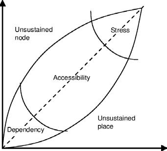
The relationship with the city and the interconnection with means of trans port are therefore inseparable in the design process of this architectural typ ology. Bertolini’s model for the railway station identifies two value identities for it: it is a node, related to the access to the transportation network it provides, and simultaneously a place, a specific part of the city with its peculiarities and potentialities for human interactions24 The balance between the complexity of the node and the comfortability of the place guarantees an accessible reality in which human interactions are crucial. This accessibility can be only sustained by a dynamic search for balance, pow ered by new necessities required by the
“The term “interchange hub” can generally refer to any facility that caters to more than one mode of trans port, [...] These modes may include na tional rail, subway, light rail, bus rapid transit, and local bus transit. There is also consideration of the interchange between public transport and the ‘feed er modes’ (walking, cycling, and private transports) used to get to and from the
tion management, with offices, stores, and maintenance yards. These areas have been constantly under evolution to face the new necessities of society. Nowadays, for instance, with the wide spread of smartphones and the possi bility of buying tickets online, booking areas are becoming unnecessary; the introduction of shopping stores and the increase in the frequency of trains has made the waiting areas lose their rea son to Theexist.station buildings are no longer simple stopping points of trains; they are now tourist attractions, shopping centers, and places of destination not only related to journeys. Therefore, the answer to the question “what is a rail way station? ” is not as immediate as it could have been a century ago.
The constant technological evolu tion of structural systems and train technologies has favored a continuous metamorphosis of the traditional sta tion design. This perpetual evolution combines with the need to make the railway system converge with all other communication links, designed to con nect the city, both externally (locally and internationally) and internally. For this reason, we can no longer talk about railway stations but “interchange hubs”.
25. Chia-lin Chen, Robin Hickman et Sharad Saxena S, “Improving Inter changes: Toward Better Multimodal Railway Hubs in the People’s Republic of China”, (Asian Development Bank, 2014), p.3.
The Intermodal Hub - Case studies 52
node and the place through time (like technological advancements or public needs). This constant search for equilib rium and adjustments keeps the station in continuous evolution, contributing to the city’s development. Therefore, it could be said that city and station are interdependent for a respective growth. This factor is one or the main reasons for the recurring choice in in serting new HST systems in inner city located stations. By the fact a railway terminus represents the main gateway to the city, this architectural typology is steady at the center of international de bates and competitions.
Fig. 17: The node-place model diagram. “In the dia gram, the y value corres ponds to the node-content of an area, or to the access ibility of the node, and thus to its potential for physical human interaction (follow ing the reasoning: the more people can get there, the more interaction is possible). The x value corresponds to the place-content of an area, or to the intensity and diversity of activities there, and thus to the degree of actual realisation of the potential for physical human inter action (according to the idea: the more activities are there, the more interaction is actually happening)”.
The international railway station can be basically distinguished in four separ ate functional areas; three of them are public: the main concourse, in which all the users converge and includes the waiting area and commercial activ ities, and the ticket area, which usually occupies a part of the concourse, and the platforms, that can be divided or not by ticket barriers. Often the latter is separated from the others by an architectural bipartition (see chapter 1.1). The fourth area encloses the sta
P r i v a t Pe ublic a c r i c r
desiresneeds vibrantandvital accessibleforall splitofhighvalueandroutineeconomicactivities
QualityofLife C
INTERCHANGEMULTIMODALHUB
53 introduction
Seaml e s s a n d I n t e gr a t e d c o n n e c t i v i t y a n d r e a l t i m e i n f o r ma t i o n metro
cycling e
o
Nowadays, interchange hubs are playing a central role in urban reality and their cultural and economic import ance is increasing. Thus, they don’t only guarantee an interconnected system of modes but also provide the opportunity to redevelop their surrounding areas proving themselves as catalysts for the city’s competitiveness, quality, and wel fare.In the most developed countries, in vestment policies have expanded and improved many stations to fill the need for high-quality and flexible interchange hubs, included in their reality. It is in
I n d i v i d u a l o mmun i t i e s
lictransport modeshare
intercity rail bus tram n t e r f a c e o f P e o p l e a n d N e t wo r k s
T r ansport N et works E nvi r onment S o c i a l N e t w o r k s
n o m i c G r o w t h
L o c a l xp ec t a t i o ns
technological Obreakthrough pt im um U s e o f S p a c e wo r k h om e le i s u r e inclusive knowledge economy attracting investment reductioninunemployment agglomerationeconomy airplane planningframeworkinvestmentpriorityandevaluation politicalleadership coop ceration onsensus lowcarbonemissions car institutional structure and power F a c ilit a t i o n of C o n n e c t i v i t y a n d T r a d e I n c l u s i o n a n d M o b il i t y walking c ycling electronic social interaction productivityentertainment S ubs t i t u t i o n a n d A d a pt a t i o n o f T r a ve lredevelopmentandregenerationglobalization public realm operationaluser internalexternal motorcycle r a ir e g io n a l r a i long-haulcoach tram train taxi
interchange station”25
this context that the figure of the global architect fits, whose task is to “create dynamic, multifunctional spaces where people can do much more than set out or arrive on a journey, [the results] are destinations in their own right, provid ing space for everything from libraries, medical centers and cinemas, to shop ping and eating. This requires greater flexibility”26. The aim is to join trans port with urban functions by creating a place in which people are allowed to move through and stop within and around it. Therefore, it is imperative to consider its integration into its local en vironment, and the outcome it will have
G
L o c a l l ob a l pe de s t r i a n l o w e n er gy de s i gn hpub
26. Malcom Smith, “Cities and Stations - Arup,” accessed April 16, ies-and-stations.com/perspectives/cithttps://www.arup.2022,
hig
UrbanDynamismandWellBeing Multilevel
E c o
I
F
C
M
o M
S e n s e o f P l a c e a c e t o F a c e C ont a c t s Interventions i t y C o m pe t i t i v e n e s s
I n s ti t u t i o n a l G o v e r na n c e ational
N
Fig. 18: The components of an Interchange Hub.
on the urban context. At the same time, however, to provide sufficient funds for the overall development, the addition of profitable elements such as offices, shopping centers, and apartments would be essential. Therefore, the plan ner might be good at adding those fa cilities without compromising the qual ity of the space. Indeed, the risk is to fall into speculative developments that only worsen the area, and this has nothing to do with improving the quality of that part of the city.
• Underground-level – they repre sent the most expensive choice but are more performing in al ready dense urban realities, in which the surroundings can re main practically untouched. As
These characteristics underline the complexities of station development in terms of design, planning, and organiz ation. They introduce one of the funda mental questions of the research: how an interchange node design can satisfy present and future human needs and how it can relate to an already formed urban context. The thesis wants to an swer this question with research by design in the context of the city of To ronto. Before doing that, it is necessary to analyze and compare intermodal hub case studies of equitable size and im portance, whose construction or expan sion led to changes and improvements in the urban context where they locate. Before analyzing the case studies into detail, it is necessary to visualize the different layouts that an intermodal hub can assume depending on how the train tracks are arranged (mean of transport more intrusive in the architectural con figuration). If the tracks end and the station hall is organized perpendicular to them, we have a “Terminal station”; on the contrary, if the tracks cross the station, organized parallel to them, we have a “Through station”. Nowadays,
the latter seems to be more efficient for what concerns the infrastructure organization. The rails, in turn, can be developed on:
• Elevated-level - they present limited flexibility for future re developments and create noise and visibility pollution but guar antee more permeability in the urban fabric.
• Ground-level - the most common and cheap to build, they have a major impact in the urban con text by creating physical barriers to cross.
Fig. 19: Station layouts based on the organization of the tracks, on the top the Terminal station with the building perpendicular to the tracks, on the bottom the Through station with the building parallel to the tracks.


54
The Intermodal Hub - Case studies
Station hall hallStation
plex structure in which transportation modes and station facilities like offices and shops are organized on different levels. The New York Penn Station and its refurbishment and expansion by S.O.M. contributed to the under standing of transportation hubs in the American context and shows important thematics like heritage conservation, rail deck construction, and urban re development.Lastly,three hyperloop hubs pro posals (BIG, UNStudio and REC archi tecture) are taken into consideration to understand how this technology is inserted in the architectural and urban context and how it in turn affects them.
Fig. 20: Aerial view of the Terminal station of Milano Centrale.

against, they cancel the visual experience of arriving in the city and complicate the connection flows within the station.
55 introduction
The case studies were selected not only on the basis of their size and relevance within their city, but also because of the peculiar elements that compose them, which can be associ ated with the intervention context of the thesis project. The Madrid Atocha station expansion by Rafael Moneo is interesting for its relationship with the heritage building, its interconnection between different means of transport and organization on different horizon tal levels. The Berlin Hauptbahnhof by Meinhard von Gerkan is a very com

57 Year of realization: 1851 foundation, 1992 Expansion by Rafael Moneo Architects: Alberto De Palacio Elissange, Rafael Moneo Gross floor area: 290.000 m2 Typology: Through station for commuter’s trains, Terminal station for national and high-speed rail Transportation modes: Domestic rail, High-speed rail, Subway, Bus, Taxi Tracks position: Ground-level + underground-level (commuters) 2.1 MADRID ATOCHA STATION
MADRID BarcelonaFigueresFigueresCuencaZaragoza AlicanteValencia
Granada Antequera Seville LisboaPorto Toulouse Bordeaux Cordoba CiudadToledoRealValladolid LéonSantiagoOurenseACoruña The Intermodal Hub - Case studies 58
Albacete

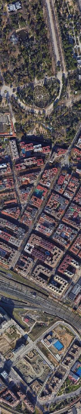
Fig. 21: (previous page) Sa tellite image of the Atocha Station area in Madrid.

Fig. 22: (on the left) Map of the High-Speed Rail network in Spain.
Urban and historical framing
accessibility and its impact within the surroundings.Inthe1980s, the need to increase rail services, with the introduction of the HSR system, to recover the main hall and the urban conditions of its surroundings, led the city government to organize a competition, which was won by Rafael Moneo. The project had to meet the requests for the renovation of the vaulted main hall and the station plaza, the construction of a new com muter rail hub connected to the subway and bus system, and a separated inter city station with parking areas.
Fig. 23: (below) Atocha Sta tion devolpment from Plaza del Emperador Carlos V.
Located in the city center, next to the Museum of Prado, Atocha is the busiest train station in Spain. It was in augurated on February 9, 1851, with the second Spanish rail line that connect ed Madrid to Aranjuez. It was the first capital station and due to the growing demand, it knew numerous architectur al interventions and expansions since 1865. In 1891, the iron and glass termin al roof was built, becoming a landmark for the city. During the XX century, the station was subjected to various small changes, that helped reducing its
59 Madrid Atocha
Rafael Moneo quadrupled the cap acity of the station and distinguished it in two parts: The historic building, whose tracks were replaced with a commer cial area, offices, and a large tropical garden; its access has been radically altered. The new one is intended for rail traffic and hosts the high-speed and long-distance train terminals on separated levels. “The resulting sta tion has a double façade, with a clock
The Intermodal Hub - Case studies 60
Moneo’s project not only satisfied these requests but aimed at improv ing the urban quality of the context in which the station is located. The main facade is indeed placed in front of a busy roundabout, at a lower level than it; this overlap of different levels increases the complexity of the pro ject and can be compared with the context situation of the design case of this thesis. The importance of its settlement is described by the archi tect in his Remarks on 21 works: “Atocha Station had been one of Ma drid’s major landmarks. As Madrid grew, the station, originally located at the edge of the city, ceased to mark the frontier with the open countryside. It evolved into an important element of the downtown area, right in the heart of the city. As street traffic increased, Ato cha’s monumental vault was gradually engulfed by a maze of elevated road ways that turned it into something like the hull of an abandoned ship”27.

Project highlights
Effects on the urban quality
Fig. 25: (above) Atocha station Cross section.

Fig. 26: (below) Atocha station Axonometry.
61 Madrid Atocha
tower marking the main entrance at the center”.28 The project included a brickand-glass rotunda entrance building, which, placed on street level, acts both as a roundabout for buses and as an ac cess to the commuter station.
Moneo’s intervention results an overlapping of different horizontal lev els above and below grade with mul tiple access points to prevent conges tion and allow travelers to reach the means of transport they need in the most effective way. The commuter sta
Fig. 24: (on the left) Atocha station Masterplan.

tion, for instance, is located at a lower level to provide easy transfer to the subway system. “The hub was actually conceived as a key architectural ele ment in solving the superimposition of horizontal planes required by the pro gram”29 .
28. Ibid.
27. Rafael Moneo, “Re marks on 21 works”, (The Monacelli Press Inc., 2010) p. 173.
The Intermodal Hub - Case studies 62

63 Madrid Atocha

Fig. 27: (left) Brick-andglass rotunda entrance building addition.
Fig. 28: (right) Detail of the rotunda façade.

The Intermodal Hub - Case studies 64


Fig. 29: (left) Commuter train station hall.
Fig. 30: (centre) Interiors of the rotunda entrance building.

Fig. 31: (right) Tropical winter garden in the former train station hall.
65 Madrid Atocha


67 Year of realization: 2006 Architects: Meinhard Von Gerkan – GMP Architekten Gross floor area: 175.000 m2 Typology: Through station on different levels Transportation modes: Domestic rail, High-speed rail, Subway (U-Bahn + S-Bahn), Bus, Tram, Taxi Tracks position: Elevated-level + underground-level 2.2 HAUPTBAHNHOFBERLIN

BERLIN Hamburg Bremen WolfsburgHannover DortmundKölnBrussels Strasbourg Innsbruck Kassel MannheimFrankfurtStuttgart AugsburgLeipzigNurnbergMünchenFuldaWurzburg HamburgGöttingen The Intermodal Hub - Case studies 68

hall was covered with an iron and glass barrel vault long 188 meters.
Fig. 33: (on the left) Map of the High-Speed Rail network in Germany.
The Berlin Hauptbahnhof is the largest multi-level interchange hub in Europe. It is located on the north west side of Tiergarten, near the gov ernmental district, on the former site of Lehrter Bahnhof. Its construction, which finished in 2006, contributed to the revitalization of a large part of Ber lin. Berlin got its first railway line in Oc tober 1838, and in 1912 the city had six large terminal stations. Among these, the Lehrter Bahnhof, built for the Ber lin-Lerthe route, was characterized by representative architecture, and the
Urban and historical framing
69 Berlin Hauptbahnhof
After the division of Germany, the station lost its importance and closed to all rail traffic in 1952. In 1990, with the country’s reunification, Berlin be came subject to massive processes of urban restructuring. One of these huge interventions was to build a monu mental station that would have helped to reaffirm the importance of the city in the European and global context. With this aim, an architectural competition was set. In 2002 Lehrter Bahnhof was demolished for setting a large building excavation for the current station.
Fig. 32: (previous page) Satellite image of the Berlin Hauptbahnhof area.
Fig. 34: (below) Berlin hauptbahnhof development.

The station is characterized by sev eral superimposed volumes articulated on three levels. The main structure consists of two quasi-perpendicular barrel-vaulted glass roofs 30 meters high. They cross in the center of the site

Project highlights
The Intermodal Hub - Case studies 70
The new interchange hub, designed by Meinhard Von Gerkan, integrates the railway transport systems of the city: the high-speed rail, the regional and commuter rail, and the S2 Bahn, organized on 16 tracks placed on two different levels to follow both the northsouth line (elevated) and the east-west line (underground). To these, two tracks of the U-Bahn (subway) are added.
Effects on the urban quality
Before its construction, the area, located in proximity to the former Ber lin wall, consisted to a large extent of inner-urban brownfields. The station played an important role in improving the surrounding area quality by setting itself as the main motor for its context development. The station wants to be a crossing building between two parts of the city, the Bundestag area, and Eur opacity. The two main facades, placed on the north-south axis, create two plazas: the north one, also dedicated as tram and bus terminal, and the south one, the large Washingtonplatz, directly connected to the government district, sets itself as a meeting place, while hosting different events during the year.
Fig. 35: (on the left) Berlin Hauptbahnhof Masterplan.
Fig. 36: (above) Berlin Hauptbahnhof Axonometry showing the organization of the tracks on the east-west and north-south directions.
NORTH
71
The purpose was to design a trans
parent building, open to everyone, not only travelers. The main hall sets itself as a crossing area for a part of the city, but also a place to stay; on the ground floor and its intermediate floors are indeed organized distribution spaces, service rooms, and all the facilities of the station but supermarkets, shops, and restaurants. In this large-scale work, the GMP Architekten studio man aged to combine the functional and technological avant-garde aspect with the formal one, capable of integrating into a city in constant renewal.
Fig. 37: (below) Berlin Hauptbahnhof Perspective cross section.
GSEducationalVersion PublicGroundfloorTransportLevel+2Level-2WEST EASTSOUTH
and cover the elevated east-west tracks and the north-south direction, which includes the main pedestrian flows at ground level. A photovoltaic system has been incorporated inside the glass skin of the arched roof, to allow the station to respond independently to energy needs. Two office linear buildings are organized along the north-south axis above the glass roof as connective bridges. These two volumes, which con tain offices and are made of a reticular structure, were built on-site and subse quently positioned above the arches.
Berlin Hauptbahnhof
The Intermodal Hub - Case studies 72

38: (left)
Ludwig-Erhard-Ufer.from
Fig. Berlin Haup aerial view.

Fig. HauptbahnhofBerlinview
39: (right)
tbahnhof
73 Berlin Hauptbahnhof

The Intermodal Hub - Case studies 74


Fig. 41: (right) Main hub hall with the east-west rail corridor.

Fig. 40: (left) Organization and use of the different levels of the hub.
75 Berlin Hauptbahnhof

77 Year of realization: 1910 (foundation), 2021 (expansion) Architects: McKim, Mead & White, S.O.M. Gross floor area: 23.690 m2 Typology: Through station Transportation modes: Domestic rail, Intercity rail, Subway, Bus Tracks position: Underground-level 2.3 NEW YORK PENN STATION

NEW YORK CITY Philadelphia New Heaven Stamford New ProvidenceLondonBoston Albany WashingtonWashingtonBaltimoreDCDC WilmingtonNewarkMetropark The Intermodal Hub - Case studies 78

Fig. 43: (on the left) Map of the Acela Rail corridor, part of the Amtrak network, connecting Washington DC to Boston.
New York City saw its first railway line in 1832. In the early 20th century, thanks to the introduction of the elec tric locomotive, the first tunnel under the Hudson River was built (instead of
Fig. 42: (previous page) Satellite image of the Penn Station area in New York City.
Fig. 44: (below) Aerial view of Madison Square Garden and new Moynihan Hall.

The Pennsylvania Station in New York City is the busiest train station in North America. It is located in Mid town-West Manhattan, beneath Madi son Square Garden and the former post office building (today the new station hall). Penn Station is at the center of the Northeast Railway Corridor, between Washington DC and Boston.
79 New York Penn Station
a massive bridge), allowing the Penn sylvania Railroad to reach Manhattan and the consequent construction of the monumental Beaux-arts termin al (inaugurated in 1910). As the Grand Central Terminal, the station had to conform to the Manhattan grid; there fore, to preserve the public streets, the tracks were put underground, this “laid the groundwork for the immense potential the station holds more than a century later”30. Due to the reduction of railway passengers after the Second World War and the lack of mainten ance, Penn Station was demolished and replaced in 1968 with an underground
Urban and historical framing
30. Derek Moore, “ Wel come to New York”, Domus Air, n.2, (July-August 2021), p.33.
29. Ivi, p.177.
The Intermodal Hub - Case studies 80

station freeing up the space for Madi son Square Garden.
Effects on the urban quality
At the urban level, the development of the Moynihan Train Hall has been an opportunity to revitalize the neighbor hood and re-evaluate the role of the railway within the urban fabric of New York City by understanding its possible implications. The aim was to enhance the public space and the neighbor hood’s attractiveness as a place to visit, live or Thework.core
of the project is based on the revitalization and conversion of the postal building, to which various access points have been opened, establish ing direct links with the surrounding streets. This intervention demonstrated to be a catalyst for the redevelopment of its surroundings even before the construction began, especially in the west area of Penn station. Here the city
To upgrade and encourage the rail way service and improve the station’s urban context, in 1997 the architecture firm SOM won the competition for de signing the new Penn station expansion. The request was to develop it inside the building envelope of the historic James A. Farley Post Office, located between the 31st street and the 8th Avenue, in front of the former station and designed by the same studio (McKim, Mead & White). The construction works of the new hall, called Moynihan Train Hall, began in 2017 and finished at the end of 2020. It hosts the new Long Island Rail Road and Amtrak headquarters.
Fig. 46: (above) Cross sec tion of the new Moynihan Hall.
81 has seen massive development of pro jects such as Hudson Yards and Man hattan West, based to some extent on the growth of the station’s rail service. These developments proved to be effi cient with the creation of new building areas thanks to innovative platforms placed above the vast railway yard and train storage areas.
New York Penn Station
Fig. 47: (below) Longitudin al section of the whole hub from the 7th Avenue to the 9th Avenue.
Fig. 45: (on the left) Penn station masterplan.development

The Moynihan Train Hall design “quite intentionally strikes a balance be tween the three poles of historic pres ervation, adaptive reuse and technically advanced architecture and engineer ing”31. The intervention consists of the extension of the existing station (under the Madison Square Garden), which is still operative.

Project highlights
31. Ivi, p.39
Due to its conversion into a railway station, the former post office building has undergone several operations of eliminations, adjustments, and addi tions necessary to the station oper ation (escalators, ticket offices, luggage areas, waiting rooms, and commercial spaces). The original floorplan, used for mail sorting, has been demolished to create a full-height hall, within which the new accesses to 17 of the 21 rail way tracks of the station are organized. A large skylight, covering the hall, is characterized by billowing lightweight diagrid steel frames holding clear glass panels, which allow abundant natur al light to enter the space below. The new elements feature an elegant and contemporary design that shows sensi tivity towards the pre-existing original industrial elements.
The Intermodal Hub - Case studies 82

New
Fig. 49: (right) Aerial view of Madison Square Garden and new Moynihan Hall. York Penn

Station
83
Fig. 48: (left) Aerial view of the S.O.M. revitalization.

The Intermodal Hub - Case studies 84


Fig. 50: (left) Detail of the entrance ceiling called “The Hive ” by Elmgreen & Dragset.
85 New York Penn Station
Fig. 51: (right) Interior and Glazed roof of the Map of Moynihan Train Hall.
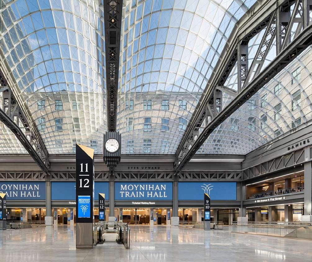

has its specificities, which are also dif ferent considering the technologies of the various companies working on vac uum transportation systems. Among the few design concepts commissioned directly by private companies, there are those of architectural firms particular ly apt at futuristic visions, such as “the Hyperloop One” by Bjarke Ingels Group for the Dubai-Abu Dhabi route, the “Hardt Hyperloop Hub” in by UNStudio and the Transpod station by REC archi tecture.Commissioned
Although there are some similarities with the railway station, such system
THE HYPERLOOPHUB 2.4
For the design of an Intermodal Hub that can accommodate a Hyperloop system suitable for passenger trans port, the study of special arrangements is intrinsic. Despite the rich state of the art of studies and demonstrations that the hyperloop system enjoys from a technological and economic point of view, there are profound gaps in terms of how the system fits into the architec tural and urban context. Indeed, as seen above, the hyperloop infrastructure can be placed either underground or elevat ed and supported by pillars. The choice of these options modifies the perception of the urban space in different ways and how the station, just as it happens with the rail system, must be designed and inserted into the urban fabric.
One, the project by BIG sees the Hyper loop stations in Dubai and Abu Dhabi as portals inserted into iconic city loca tions, such as the Burj Khalifa area in Dubai. The project is based on a 2016 concept in which passengers travel in
Fig. 52: Hardt Hyperloop concept for a station in The Netherlands.
by Virgin Hyperloop
87
The Intermodal Hub - Case studies 88
Fig. 53: Exploded perspec tive for the Dubai Hyper loop Hub.
32. Bjarke Ingels Group, “Formgiving”, (Taschen, 2020), p.68.

pods with room for six people, which in turn are organized in sets of four inside transporters that transport them in the tubes at speeds of 1100 km/h. The idea is that these small pods can operate autonomously from the transporter, “which means they are not limited to the portal area and can move on regu lar roads and pick up passengers at any point”32. Stations are seen as endpoints since transporters only travel directly
Fig. 54: (above) Hardt Hyperloop concept station - in and out people flows scheme.
UNStudio 2018-vision for Hardt Hyperloop in The Netherlands iden tifies a common approach for future European Hyperloop stations based on modularity. The design research aims to study the different possibilities of introducing the Hyperloop system in the city and towns of different sizes and contexts. As declared by the firm,
The Hyperloop Hub

to their final destinations. The aim of the design concept is to eliminate the wait ing time that passengers experience, by separating the arrivals and departures flows, making all the gates visible, and guaranteeing a huge number of tracks for the pods. The station system, based on a spiral loop, can be adapted to any context by changing the radius of curvature and the revolution numbers of the spiral.

Fig. 55: (below) Hardt Hyperloop concept stationplatforms area.
33. “Hardt Hyperloop,” UNStudio, accessed March 12, 2022, hardt-hyperloop.dio.com/en/page/11735/http://www.unstu
89
“Modularity is what makes this sys tem scalable, resilient, and adaptable to existing conditions [..], It blends into the built fabric whether above or over ground, in dense inner-city neighbor hoods or in low-rise settings”33. The de sign example is an integrated hub with a large terminal station facility with underground infrastructure in a hypo thetical suburban area of a city. The en vironments and facilities are arranged on two levels: the Platform and the Concourse level. Both are organized through a modular scheme that can be enriched or reduced depending on the context and needs. As in the previous case, the design aims at separating the departure and arrival flows and seeks to facilitate the passenger experience
by grouping all the gates and the plat forms into one large environment cov ered by a glass canopy, also based on a composition of modular elements. Here, unlike BIG’s Project, the connec tion between pod and platform is medi ated by airlock accesses, and the pods travel directly within the tubes without intermediate conveyors. The station is entirely powered by photovoltaic panels placed throughout the infrastructure system. This energy is stored in specific areas of the hub and can be used for direct management of the internal en vironment but also to power third-party elements, such as buses and electric vehicles.Differently from its predecessors,
Fig. 56: The modular design framework that can be adapted to different scenarios.
The Intermodal Hub - Case studies 90
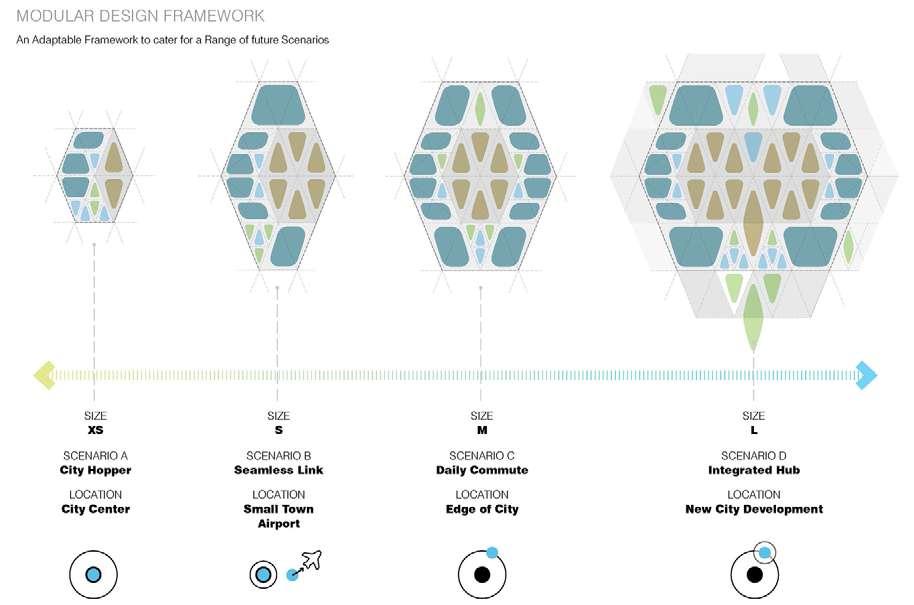
the concept for TransPod follows the directions for an intermodal hub with tubes organized as a Through station and not a Terminal station. In this design example, the tubes run above ground on pillars contiguous to the rail tracks and the station building bridges over the infrastructure to connect the differ ent modes of transportation. Here the passenger follows a guided route that, after security controls, reaches the top floor where the gates are placed. The
The
Hyperloop Hub
latter are directly connected to the platforms located at a lower level. The docks are longer and smaller in num ber if compared to the other examples. This because the company aims at cre ating pods that accommodate up to 50 people and travel with high frequency. Among the topics also present, there are the idea of a self-sustained building from an energy point of view and the separation of departure and arrival flows of people.
91
The hyperloop station shares common features not only with train stations but also with airports and subway stations.
In the analysis of Atocha, Berlin Hauptbahnhof, and Penn Station and their context before their design inter vention, we can highlight interesting analogies with the project area of this thesis, the Union Station in Toronto (see chapter 4). All three interventions pro duced a positive outcome, both in the use and the operation of the station and in the increase of the quality of their surroundings. The analysis of the con text and pre-existence, the integration with people flows, and the adaptation to contemporary technological needs, were found to be crucial for the result.
SYNOPSIS 2.5
All three cases show a particular focus on the entrance hall, both as an interchange place and as a living point of the city to walk through but also lin ger with citizen facilities and commer cial spaces. Berlin Hauptbahnhof, in particular, is conceived as a crossing point between two emerging areas of the city. Here means of transportation are showcased and organized on mul tiple levels through the use of innovative structural and technological systems. The aim is to make the interconnection
cance dictated the improvement of the intermodal hub. In both the latter cases, the project aimed to adapt itself to the pre-existing historic building without changing its connotations but by acting on its function and internal organiza tion, to improve flows and connections with the context.
For Berlin the design action was free because it was based on the con struction of a building from scratch in an almost empty area, while for Atocha and Penn Station the architectural and urban constraints of historical signifi
93
work efficiently between elements of the hub and amplify the perception of “interchange” with the urban reality. An overlay on horizontally connected lev els also proves to be efficient in the case of Moneo: the extension of the street level over the track level ensures the organization of multiple accesses to im prove flows and reduce the possibility of congestion. Furthermore, the case of Penn Station is useful in understanding how such an action can work in a high ly automobile-dependent reality: that of North America. The aim is not only to encourage the use of environmentally friendly means of transportation but also to improve the public realm quality of the surrounding area.
high frequency
tem. To do this, however, it was neces sary to understand which elements and features should be considered when designing an intermodal hub that could accommodate the hyperloop system.
Fig. 57: Keywords for each traditional transportation system (airplane, train and subway). In blue the characteristics shared with the hyperloop system.
cozyness far from the citypaycentreforthe luggage low frequency high emissions internationalnational&retailfoodanddestinationsbigarchitecturalbuildingeconomicandbusinessclasseslongdistanceslowimpactonthelandscape
AIRPLANE TRAIN SUBWAY
commuter uses ticket machines
ticket office several platforms
no architectural building low emissions low soil consumption
94
waiting on platformsthedriver
retail & food in the main stations
The Intermodal Hub - Case studies
ticket controls on the train sustainable technology long travel time usually next to the city centre mediummediuminstitutionalimportancefrequencywaitingtime
low waiting time access throughself-driventurnstiles
By analyzing the design experiments of BIG, UNStudio, and REC Architecture, it is clear that the hyperloop station is a sort of hybrid of airport, train station, and subway station [Fig. 57]. The most evident similarity of a Hyperloop station with an airport is the organization of the security controls, more meticulous due to the international connections. The controls are divided into two steps: the first one being luggage and people security controls, usually in proximity to the entrance hall and dividing the public space from the fare zone, and the second one being the ticket control at the gate that permits the boarding. After the boarding, the hyperloop sta tion has features more similar to a subway station because of the smooth
no landscape view no impact on the landscape notconnectsexpensiveparts of the city and even different cities
The goal of this thesis aligns with the outcomes obtained from the case studies, aiming at improving the public realm of the station area, in this case of Toronto, by going to implement the cur rent hub with a new transportation sys
landscape view
no security controls high number passengersof stops in all the stations suburbs
immigration offices pilot gates check-in security controls long waiting time over-sea destinations
short travel time
Thus, the analysis of these case studies has been essential for the defin ition of the design process, which, how ever, needs
connection between the platform and the mean of transport and the waiting times, reduced to the minimum, recall the high frequencies of the subway. The presence of different platforms resem bles the train station conformation.
Among the factors that seem to be
Synopsis95
common in these design examples, there is the search for a modular sys tem that can be repurposed in different areas. This factor is particularly char acterizing in the case of UNStudio; here, the repetition and composition of mod ules aim to simplify and meet dimen sional and connection needs but risk detaching from the architectural and urban context in which it is inserted.
The aim is to create a smooth place where departure and arrival flows are separated and minimize waiting time. Waiting areas are thus reduced to the limit and, in addition, due to the mass use of personal devices, there is no longer a need for ticketing areas.
TORONTO
3
»
- R. Koolhaas
« Toronto suffers from neglect. Of all major North American cities Toronto spends the lowest amount on public space. No major city spends less on park operations. Can Toronto survive as urban beauty becomes increasingly important to a city’s prominence in the world marketplace? Will Toronto’s own negligence turn Canada’s central hub into a peripheral global city? Despite its derelict spending, Toronto has the opportunity to convert the city’s one inherent asset into its greatest civic amenity.
99 introduction
Toronto is the capital city of the Can adian Province of Ontario. The city’s configuration, its recent development and growth are a few of the many as pects that make the city of Toronto the most interesting area for the develop ment of the project. In this chapter, we are going to analyze the main topics
that draw our attention to this city. Starting from a general point of view, we looked into the North American con text because of its long-distance travels across the nations and, more precisely, in Canada due to its lack of high-speed rail connections. We then found inter est in Toronto because of the possible hyperloop routes studies and the cur rent growth of the city.

Long-distance travels in North America
Fig. 58: Toronto Skyline from Toronto Islands.
34. US Census Bureau, “Census.Gov” Census.gov, accessed April 12, en.html.https://www.census.gov/2022,
35. Statistics Canada Government of Canada, “Census of Population,” January 15, 2001, dex-eng.cfm.census-recensement/inwww12.statcan.gc.ca/https://
A similar situation happens in Canada, where the largest cities by population are located in the east part of the coun try (Toronto and Montréal) and in the west part (Calgary)35
WHY TORONTO?
36. The travel time has been calculated through Google Maps www.viarail.ca/).VIAhasproposedgoogle.com/maps)and(https://www.thetravelitinerariesbeencheckedontheRailwebsite(https://
This produces a dilatation of travel time and, as an example, it takes four days to travel by train from Toronto to Vancouver (4.550 km)36. The same travel only takes five hours by airplane. Seen this travels times, made us won der what the travel time for the same distance in the European context is. We compared the travel from Lisbon to Athens, cities located at almost the same distance (4.600 km) as Toron to and Vancouver. We discovered that it would take three days to travel by train, crossing several different coun tries and changing several trains, and four hours by airplane. We then noticed
3.1
101
North America covers the 16,5% of the Earth’s total land area and is composed of three countries: Can ada, the United States and Mexico. Due to its scale, even the distances between the cities of the same country are very significant. For example, in the United States the largest cities by population are located on the two coasts of the state – the East Coast, with New York and Philadelphia, and the West Coast, with Los Angeles and San Diego – and on the borders with Canada and Mex ico – the northern border, with Chicago, and the southern border, with Huston and Phoenix34 . This peculiar disposition of the cities in the U.S. leaves the cen tral part of the state with few big cities.
are high speed trains for long distan ces. This introduces another important thematic that makes Canada one of the most suitable areas for the introduc tion of the hyperloop system: the lack of high-speed rail in the country. To this day, Canada is the only G737 country without High-Speed Rail (HSR), while the U.S. place themselves as the nation with the worsts high speed rail net work. In contrast, China built, in only twenty years, the largest high speed rail system in the world, which is more than all the other countries networks combined38 Canada’s. approach to HSR occurred sporadically with the Turbo Train39 from 1968 to 1982. The Turbo Train, managed by Canadian National Railway Company (CN), connected Toronto and Montréal in
Canadian Pacific (CP) Canadian National (CN)
39. David Bellerive, “UAC TurboTrain”, Rail Fans Canada, accessed April 12, 2022, gines/uac-turbotrain.fans.ca/via-rail-canada/enhttps://www.rail
102
38. Mike Colledge. “Should Canada Expand Train Trav el?”, (Ipsos, 2017), p.3.
WinnipegCurchillSioux Lookout
The fact that in Europe it takes two hours less to travel the same distance by train is given by the fact that there
37. The G7, born as G8 in 1975, is an informal forum that brings together the leaders of the world’s leading industrial nations: Canada, France, Germany, Italy, Japan, the United Kingdom and the United States.
Toronto
Prince Rupert Hay River Thunder BayChicago
Toronto that, not only it is difficult to travel from one coast to the other without using an airplane, but the distance is significant also between the cities located on the same part of the country. As another example, Toronto is located 542 km from Montréal, meaning a five-hour long trip with the train and a one hour and twenty minutes flight. A similar dis tance is the one separating Milan from Rome (600 km) and it takes three hours by train and one hour and ten minutes flight. The railway system in North America
OttawaJonquièreSenneterre White River
WindsorSarnia Halifax MatapédiaMontréalQuébecMonctonGaspéSackville
Toronto The Pas Regina Thompson Saskatoon
CalgaryEdmontVancouverKamloopsJasperPrinceGeorge
SudburyLondonNiagaraKlingstonFalls
Toronto
ica, that currently connects Toronto to Montréal. Currently, neither of the two options are under consideration.
WinnipegSioux Lookout
Fig. 59: (left) Canadian Railway system managed by Canadian Pacific and Canadian National.
Fig. 60: (right) Frequency of rail connections in Canada.
Interest in a hyperloop development
MatapédiaMontréalQuébecMonctonGaspéSackville
less than four hours. The project had to be stopped after persistent mechanical issues with train engines and, “in 1977, VIA Rail, a crown corporation, was es tablished and took over operations for the last few years of the Turbo Train’s existence”40 .
Prince Rupert Hay River Curchill
6-7 trains/week (each way)
After the fourteen-year experience of Turbo Train, Canada never experi enced HSR again, but the interest in creating an HSR network remained through the years, mainly because it would represent a cheaper alternative to domestical flights.
SudburySenneterreOttawaJonquièreKlingstonNiagaraFallsLondon
White River
WindsorSarnia Halifax
> 2 trains/day (each way)
HSR is aimed at increase business relations, especially in the Toronto-Ot tawa-Montréal area, in order to reduce the CO2 footprint of road travel and to relieve the traffic from 401 highway, one of the busiest highways in North Amer
VancouverKamloopsJasperPrinceGeorge
Another reason why Toronto has been chosen as the city in which de velop this thesis project is the interest in connecting Toronto to Montréal with the Hyperloop system by many of the companies working on the develop ment of this new technology. In 2017 Hyperloop One proposed this route as one of the ten strongest ones for the hyperloop system, while TransPod company explored the possibilities of connecting several Canadian cities through the vacuum tubes. Among the routes, there are the Toronto-Montréal
40. Mike Colledge. “Should Canada Expand Train Trav el?”, (Ipsos, 2017), p.3.
3 trains/week (each way)
103
2 trains/week (each way)
Why Toronto?
The Pas Thompson Saskatoon Edmont
The third RLB Crane Index® of last year was published on September 28th, 2021. Three of the 14 cities surveyed have experienced an increase, five are stable and six of them have witnessed a decrease. While the overall report shows a 4,5% decrease in cranes from the first report of the year 2021, Toronto shows an 8% increase in the same per iod and an 81% increase in one year. To ronto is also the city that hosts 49% of the total cranes; followed by Los Angel es (11%), Seattle (8,5%), and Washington D.C. (7.5%). Toronto’s growth confirms the predominancy of residential and mixed-use projects on the market. Even though the number of projects has in creased in the past few years, the sec tor was not affected by the economic slowdown caused by COVID-19.
The RLB’s Crane Index® is import ant because it counts the number of
The growth of Toronto can be wit nessed also in other sectors, e.g., in the building constructions. With 225 cranes
44. Jordyn Posluns. “Toronto Ranked #1 For ‘Population Growth’ In North America”, Narcity Toronto, June 3, north-america.than-anywhere-else-in-lation-is-growing-faster-toronto/torontos-popuhttps://www.narcity.com/2019.
104
To this day, the hyperloop Toron to-Montréal corridor and, in general, connecting the big cities near Toronto, stays as one of the most interesting routes for the introduction of the new technology. To prove this high interest from Canada in the hyperloop system is the fact that TransPod company was founded in 2015 Toronto and even today continues to develop the system and the possible new connections.
43. Frank Clayton, and Shi Hong Yun, “ WOW! Toronto Was the Second Fastest Growing Metropolitan Area and the Top Growing City in All of the United States and Canada”, Toronto Metro politan University, May 31, 2019. blog/blogentry35/.search-land-development/tomu.ca/centre-urban-rehttps://www.toron
Toronto’s current growth
Since at least the last decade, To ronto has been experiencing a huge growth, both territorially and demo graphically. According to a study pub lished by Toronto Metropolitan Univer sity’s42 Centre for Urban Research and Land Development on May 31, 2019, and developed by researchers Frank Clayton and Hong Yun Shi, in 2018 “To ronto was the second fastest growing metropolitan area and the top growing city in all of the United States and Can ada”43. In fact, its “population increased by 77.000 net new residents in the year ending in July 2018”44 .
41. Yasmin Aboelsaud, “Canada Officially Investing in Hyperloop Transpor tation Concept” accessed April 8, 2022, ada-tender-2019.to-montreal-transport-cantranspod-hyperloop-torondailyhive.com/vancouver/https://
45. Boston, Calgary, Den ver, Honolulu, Los Angeles, Toronto, Washington D.C., Chicago, New York City, Portland, Seattle, Las Vegas, Phoenix, and San Francisco.
at work by the end of 2021, Toronto was ranked by the RLB’s Crane Index as the city in North America with the largest number of major construction projects. The Rider Levett Bucknall’s Crane In dex® for North America is a report that aims at counting the number of fixed cranes on construction sites 14 major cities in the U.S. and Canada45
Toronto and Calgary-Edmonton corridors. In March 2019, Transport Canada was commissioning the study of the Hyper loop, so it can be “better informed on the technical, operational, economic, safety, and regulatory aspects of the Hyperloop and understand its con struction requirements and commer cial feasibility”41
The last RLB Crane Index® was published on March 29th, 2022 and confirms Toronto as the city with the majority of fixed cranes (it has been the leading city since 2015). Since the last report, cranes in Toronto have been increased by 12% from the last report, making the city the leading one with 252 fixed cranes at work, more than the number of all the cranes present in the other surveyed U.S. cities (203).
42. Formerly Ryerson University.
Calgary(35)
NewBoston(13)York(10) Toronto(208) Washington, DC (45) Chicago(12) Portland(23)Seattle(43)
report highlights the constant growth of the city that it can be espe
ongoing construction projects in North America. By comparing the crane num bers, it is clear that Toronto is the city that is growing faster and that there is an interest in building more commer cial, residential and mixed-use build ings.The
in
San Francisco(11) Las (2Vegas) Los (41)Angeles Phoenix(9) Denver(22)
Why Toronto?
Fig. 61: Number of cranes per city North America in the first trimester of 2021.
105
cially witnessed in the waterfront area. In fact, the area was, at the beginning of the century, nearly empty and, through the last twenty year it has been pro gressively constructed, reproducing the dense urban pattern of skyscrapers of the Downtown.
107
introduction
Since its foundation, Toronto has always been separated from Lake On tario. This division has been even more marked by the functional specialization of the waterfront area and, in the 1950s, by the construction of the Lakeshore Expressway (renamed Gardiner Ex pressway in 1957).
Fig. 62: Toronto Nolli plan.
3.2
CITY EVOLUTION
year of urban Toronto, with the start of the construction of Fort York and the Toronto Purchase agreement that for malized the acquisition of the territory by the British from the Mississauga peoples. In 1805 there was a second To ronto Purchase agreement due to some illegitimacy of the first one. After these events, the formal foundation of Toron to (previously York) can be dated to the beginning of the XIX century.
The area in which Toronto is settled has been, for millennia, inhabited by indigenous people – the Mississauga people. After the discovery of the Amer ican continent by Cristoforo Colombo in 1492, the colonization era started. Since the 1600s Toronto’s land was used as a passage by the French people and, only in the 1720s, the French settled there a small trading post, symboliz ing their interest in the area. After the American Revolution, which occurred in the second half of the XVIII century, To ronto became an important site for the fur trade and as a settlement, because the British believed Toronto would be a perfect site for a naval base. The year 1793 is commonly considered the birth
19121834 202218861981 1959
Toronto, like many major cities around the world, has been founded near a major body of water, in order to favour the port trade activities. In fact, Toronto is located on Lake Ontario, the first Great Lake from the St. Lawrence River, which has been contributing to the growth of the city ever since. A big part of the city’s trade has been histor
46. Waterfront Toronto, “History & Heritage”, Waterfront Toronto, accessed April 15, ory-heritage.toronto.ca/about-us/histhttps://www.waterfron2022,
ically linked to boat shipments, pushing the manufacturing facilities to locate on the lakeshore, in order to allow “sup plies to be easily received and finished products to be effectively transport ed”46. But in the 1830s and 1840s, the area along the waterfront was satur ated, severely limiting the industrial growth and the introduction of the rail way infrastructure.
Relationship with Lake Ontario
47. ERA Architects, “Herit age Impact Assessment: 141 Bay Street”, (Era Architects, 2018), p.13.
108 Toronto
Fig. 63: Toronto’s land reclamation in Lake Ontario from 1834 to 2022.
Toronto’s expansion into the water
City evolution
The first barrier: the advent of the rail way
Since the arrival of the railway, To ronto has been divided from its water front by this infrastructural barrier. The construction of the current Union Sta tion (see Chapter 4) implied a massive modernization of the rail facilities and “the land south of the station came to be dominated by rail and industrial ac tivity in response to the rapidly expand ing economy and a continual increase in passenger activity”50. As a conse quence, the area has been significantly monopolized by the expansion of the rail yards of both Canadian Pacific and Gran Trunk Railway. It is in this period that the Toronto Viaduct, a ten kilometers long elevated bridge, was built as a way of separating the rail activity from ped estrian traffic going to the harbour in
the Esplanade accommodated then the railway, bringing Front Street back to its original function as a city street. Two years later, the first Union Station (see chapter 4), located at York Street and Front Street, was completed. Thanks to the arrival of the railway, Toronto increased its industrial and port ac tivities on the waterfront. As a conse quence, the expansion of the shoreline continued to support the expansion of both the industrial and rail industry. In the year 1888, the shoreline had moved 200 meters into Lake Ontario, generat ing usable land to the waterfront. The original shoreline corresponds with today’s rail corridor. The shoreline in filling continued throughout the XIX century and “until the 1950s when the modern shoreline was achieved”49 .
109
48. Ibid.
49. Waterfront Toronto, “History & Heritage”, Waterfront Toronto, accessed April 15, ory-heritage.toronto.ca/about-us/histhttps://www.waterfron2022,
Before the arrival of the railway in Toronto in the 1850s, the historic shore line of Lake Ontario was marked by Front Street (hence the name). Here, the city’s elite resided adjacent to the House of Assembly at Front and John streets. “Subsequent to the completion of the railroad in 1853, Front Street evolved from a genteel residential ad dress along the water to a bustling in dustrial port”47. The phenomena that characterized Toronto’s waterfront, that is reclaiming land by shoreline in filling, began in 1856 with the creation of The Esplanade, a 30 meters wide em bankment into the harbour48. In 1856, with the completion of the Grand Trunk railway between Toronto and Montréal,


50. ERA Architects, “Appendix 4 - Heritage conservation district plan”, Union Station District Plan, (Era Architects, 2006), p.28.
Fig. 64: (above) Toronto Waterfront area map of 1834.
Fig. 65: (below) Toronto Waterfront area map of 1857.
110 Toronto
the south. Its sequence of events has been characterized by disagreements between the City of Toronto and the railway companies and regarding the financing and functioning of the viaduct that last for almost ten years.
to and Metro Centre (see chapter 3.2), were proposed, being the latter partial ly realized. By the 1990s a big part of this land was developed to public use and important public buildings, such as Roy Thompson Hall (1982), the Metro Toronto Convention Centre (1984), the CBC Centre (1989) and Metro Hall (1992), were built. A small collection of former warehousing buildings located at Front and Simcoe streets are the only remaining of the area, symbolizing the past functions of that land.
With the institution of the Toronto Waterfront Revitalization Corporation in 2001, the rail lands and the central part of the waterfront have regained attention and, through the revitalization process, become an important vibrant public space for Toronto.
51. Ivi., p.34
Fig. 66: Toronto waterfront area in 1920, aerial view.
Subsequent to the Second World War, many industrial functions left the city centre in favour of the periphery. This made “many industrial zones and rail yards within the Union Station Dis trict became obsolete”51 and the debate about their future function started. The first part being decommissioned was the one hosting the rail yards north of Front Street and, in the 1960s it was transformed into parking areas for the Finantial District that, at that time, was subjected to a huge growth. This area was then followed by the entire decom mission of the rail yard in the south and, it is in this period, that huge urban developments, such as Project Toron

City evolution
Fig. 67: Toronto waterfront area in 1985, aerial view.

Since the 1970s, all across the world started a common movement where cities began to redevelop their water front and, by doing so, put themselves onto the world stage because “their newly developed waterfronts attracted more residents, more employers, more jobs and more visitors”52. Toronto start ed this revitalization process of the waterfront area only at the beginning of the XIX century, as it will be explained later in the chapter 3.2, but the results were fast and completely changed, in twenty years, the area, making Toron to discover a new relationship with its waterfront.
111
way, an elevated highway that runs east-west between the current rail cor ridor and the shoreline.
52. Waterfront Toronto, “History & Heritage”, Waterfront Toronto, accessed April 15, ory-heritage.toronto.ca/about-us/histhttps://www.waterfron2022,
The railway was not the only barrier that divided and continues diving even with the creation of the Toronto Via duct, the Downtown of Toronto from its waterfront.Duringthe years after World War II, Toronto’s relationship with its water front completely changed. Since the waterfront was now completely occu pied by industries, citizens that lived in the downtown core started, also thank to the affordability of cars, to move to wards the cleaner areas of the suburbs. However, because people continued to work in the Downtown and in the indus trial areas, new roads and highways were constructed to enable commuting. This phenomenon led, in the 1950s, to the construction of the second barrier that divides Toronto’s Downtown from its waterfront: the Gardiner Express
The second barrier: the advent of Gar diner Expressway
112 Toronto


113
Fig. 68: (left) Railway yards behind Union Station between 1982 and 1988.

City evolution
Fig. 69: (right) Waterfront area between Front Street and the Gardiner Express between 1975 and 1987.

THE CITY BENEATH TORONTO
Toronto, like many other North American cities, has developed an underground city network, that takes the name of PATH, to contrast the strong weather conditions affecting the city. In fact, hot humid summers and long cold winters encourage the development of different types of indoor pedestrian networks. The underground system can be found in Montréal (RÉSO), sky ways in Calgary (+15 Skyway) and Min neapolis (Minneapolis Skyway System) and a combination of both in Chicago (Pedway) and Toronto (PATH).
3.3Fig. 70: pedestrianUndergroundPATH.
The PATH is the world’s largest underground pedestrian complex and, with its 30 km of underground routes, can be considered a city in itself. It con nects more than 75 buildings, and it is approximately six blocks wide and ten
115
tourists.Theunderground system of Toron to’s development is both planned and accidental. In fact, in the 1950s a plan network was officially proposed, but the city was already experiencing spon taneous underground connections. The first underground connection of the city has been established in 1900 when the T. Eaton Company Ltd. linked its main
blocks long. It provides access to six subway stations, Toronto’s busiest tran sit hub (Union Station and the bus ter minal), office towers, department stores and hotels, as well as City Hall, Metro Hall, and entertainment buildings, such as the Roy Thomson Hall, the Scotia bank Arena, and the Eaton Centre. The PATH is used by 200.000 business-day commuters and additional citizens and
116 Toronto
Fig.4.ChronologicaldevelopmentoftheTorontoundergroundnetworkinthepastcentury(1917,1971,1993,2006).
7 TheRoyalYorkHotelisnowownedbyFairmontHotels&Resorts.
The Downtown core witnessed an other significant growth in the 1980s and 1990s and new skyscrapers were added to Toronto’s skyline. The system of the PATH is developed completely underground in the Downtown area until it meets Union Station. Here, con nections are provided both below and above ground. The Toronto Skywalk connects, by passing over the rail tracks, the train station and the UP Ex press building to the plaza in front of the CN Tower, the Rogers Centre and Ripley’s Aquarium. In the last fifteen years, the PATH expansion interested mostly the area south of Union Station. Here, skywalks have been constructed instead of underground tunnels be cause the area is on artificial land, mak ing the PATH system a combination of
store (178 Yonge Street) to the other company possessions with an under ground tunnel, arriving at five tunnels in 1917. In 1927, with the opening of Union Station, another tunnel was built. It linked the arrival area of the train station to the Royal York Hotel (today Fairmont Royal York) across the street. Since World War II the system was not further developed until the construction of the first subway in Canada between 1949 and 1954, making the under ground connections even more logical.
‘‘Thegrowththatwascomingpresentedseveralproblems.Thesidewalksweretoocrowded–by1960,people werespillingintotheguttersatrushhour–andthere wasnoaffordablewaytowidenthem.Drycleaners,restaurants,andotherserviceswerevanishingfromthe streetsbecausetheydidn’tfitintothenewcorporateaesthetic.Thosewhowereputtingupbuildings,especially banks,didn’twantthelogosofhamburgerjointsand camerashopsclutteringtheirelegantfacadesandblurringtheircorporateidentities’’.9
that had the aim of privileging streets over underground tunnels. The city’s attempt succeeded in bringing people again on the sidewalk but, owners of the buildings kept wanting to be con nected to the PATH system. By the end of the 1980s, the city of Toronto become the coordinating agency of the PATH and commissioned its signage designs.
Fig. 71: (on the left)
WiththeadventWorldWarII,nofurtherdevelopment ensueduntiltheconstructionofCanada’sfirstsubway between1949and1954.Connectionstotheunderground nowseemedevenmorelogical:subwaystationsandmezzaninelevelscouldbelinkedunderthestreets.Thecentral planningideologyof‘separatingpeoplefromtraffic’during the1960slaidthegroundworkforMatthewLawson–city planningcommissionerbetween1954and1967–who imaginedthat‘‘muchofthefutureofdowntownwasbelow grade’’.Lawson’sPlanoriginallyconsideredtheburialof motorcarspriortothedevelopmentofanunderground pedestriannetworkbutthedisruptioncausedbytheconstructionandthecolossalfinancialinvestmentrequired madeitimpossible.
The city beneath Toronto
9 Fulford, AccidentalCity:theTransformationofToronto,44.
Undergrounddevelopmentexplodedinthe1960sand 70s(Fig.4).Toensureaminimumqualityandconnectivity tothespace,thecityplanningdepartmentsubsequently decidedtoparticipateintheconstructionofadditional concourseelementsbysubsidizinghalfofitscost.Thelobbyingandcost-sharingeffortwasnotnew,infactitwasinitiatedapproximatelyadecadeafterthefirstsuccessful exampleinMontreal,thePlaceVilleMarie(PVM) designedbyIeohMingPeiwithitscentralunderground shoppingcomplex.8 Moreimportantly,theinitialdevelop-
Inmanyways,theTorontoundergroundwasalmosttoo successful.Bythemid1970s,streetsandsquareswere reportedlybeingdrainedbytheeffectivenessoftheclimate-controlledandsuper-connectedunderground.10 The
morepronouncedintheUnitedStates. 276 P.Be ´ langer/TunnellingandUndergroundSpaceTechnology22(2007)272–292 117
8 Completedby1962,PlaceVilleMarie,or‘‘PVM’’asitisalsocalled, becameashoppinglandmark.AsauthorPierreBertonwroteinthe TorontoStarthatyear:‘‘Thereisnolongeranysensetalkingaboutthe racebetweenMontre ´ alandToronto.Forthemomenttheraceisover. Montre ´ alhaswon.PlaceVilleMariehasputitadecadeaheadofus’’ (SourceUnknown).Montreal’squantumleapisalsoresultofseveralmega projectssuchasPlaceBonaventure,the6-acremulti-functionalcommercialcomplexbuiltby1966andtheMe ´ tro,thefirstrubber-tiresubway
But Toronto’s underground network witnessed real growth in the 1960s and 1970s when the ideology of separating pedestrian traffic from the vehicular one spread among city planners and architects53. The city planning depart ment decided to participate in this huge expansion of the underground network and succeeded maybe too well. In fact, by the second half of the 1970s, the streets and the squares were almost empty, while the climate-controlled and well-connected underground was full of pedestrians. This led to the in stitution, at the end of the 1970s, of a reformist “anti-underground” council
Stationinthe1920s–Canada’slargestregionalrailstation modeledonGrandCentralStationinNewYork–another tunnelwasbuiltjoiningthearrivalsareawiththeRoyal YorkHotel7 acrossthestreet.Thesetwonodes,oneat thenorthofthedowntownareaandtheotheratthesouth end,formthemainextremitiesofthenetworktoday.
Fig. 72: 1993,theundergrounddevelopmentChronologicaloftheTorontonetworkinpastcentury(1917,1971,2006).
53. Pierre Bélanger, “Underground Land scape: The Urbanism and Infrastructure of Toronto’s Downtown Pedestrian Network” Tunnelling and Underground Space Technology 22, no. 3 (May 1, 2007): tust.2006.07.005.https://doi.org/10.1016/j.272–92,

Current PATH system with underground and elevated network.
systemintheworldbuiltforExpo‘67.
10 Fromamacro-economicperspective,theproliferationofshopping mallsandexpresswaysaroundthecityofTorontointhe1960sand1970s aretwoofthemostimportantfactorsthatledthedrainofdowntown streetlifeandretailactivity.In1964forexample,theYorkdaleShopping CentrebecamethelargestmostpopularmallsinCanada,attracting developersfromGermany,France,Switzerland,BritainandHollandon theirNorthAmericantoursofcuttingedgeshoppingcentres.Withlarger malls,higherceilings,air-conditioning,largeparkinglotsandextended operatinghours,suburbanshoppingcentreseclipsedretailactivityon downtownstreets.Architectandurbanist,VictorGruenprovideda comprehensivedescriptionofthisphenomenonin TheHeartofOurCities (NewYork:SimonandSchuster,1964),aphenomenonthatwasmuch
mentoftheundergroundisprincipallyduetoalegislative loopholeratherthanadesignguideline:below-gradespace wasnotcalculatedaspartofmaximumdensityallowances. AlsoknownastheFARforFloorAreaRatio,theloopholefreeddeveloperstobuildadditionalconcourselevels withoutsacrificingbuildingheights.Followingthesuccess ofthePVMFormula,undergroundshoppingconcourses –merelybigbasements–becamecorporateincentivesin Toronto,primarilybuilttoattracttenantstotheoffices above.Transitaccesswassimplyanaddedbonus.Ameans ofrelievingsurfacecongestion,Lawson’sPlanalsohad unintendedconsequences:
Fig. 73: (below) Eleveted PATH network crossing over the rail corridor.
starting from Union Station. In fact, dur ing the business mornings, there is not only the south-north flow from Union Station but also a new north-south flow of workers that go to the offices in the waterfront area. After work hours, just as the Downtown workers do, they re turn to Union Station and, from there, they continue their commute to the new residential area of the waterfront. This creates a clash of the two flows when they meet in the transport hub and also of the residents and commuters. It is clear that rethinking the connections and routes becomes a necessity.
Fig. 74: (on the right) The Eaton Centre in Toronto as a part of the PATH system.
below- and above-ground connections. These elevated tunnels link buildings but also bring people to the water front area through a climate-controlled space. In fact, until the beginning of the new century the pedestrian traffic of the PATH, during business days, was divided into south-north in the morning (inbound) and north-south traffic in the late afternoon (outbound), today the situation is more complicated. As con firmed by Leon Lai, partner on the De sign Review Panel of Waterfront Toron to (see chapter 3.2), during our meeting on October 5, 2021, to this day, a new strong flow of people is generated
118 Toronto

119 The city beneath Toronto


UNBUILTCOULDWHATPROJECTS:TORONTOHAVEBEEN
(proposed in 1942 and abandoned in 1980), while others implied large-scale urban and architectural interventions. In the last category, we can find the famous Metro Centre by WZMH Archi tects, the Toronto Project by Buckmin ster Fuller and Union Station revitaliza tion competition of 2001 by OMA.
introduction
Toronto has witnessed the proposal of a series of ambitious urban planning projects that were never built. Some of them were focused on the infrastruct ural aspect, such as the Spadina Ex pressway54 (proposed in 1949 and fiz zled in 1971) or Queen Street Subway
3.4
121
Fig. 75: Construction of the CN Tower in 1975. 54. A portion of it did get built.

123
Metro Centre - WZMH
Unbuilt projects: what Toronto could have been

Canadian National and Canadian Pacific, controlling jointly this big piece of land in central Toronto, saw the opportunity to transform for specula tive purposes an area whose utilization has been limited to rail transportation functions, even though they stated it was in their interest in creating “a lively and livable core in Metropolitan Toron
Metro Centre was, with its 187 acres of office towers, apartment buildings, shops and schools, the largest down town redevelopment scheme in North American history. It was considered a mixed-use “city-within-a-city” with 418,000 square meters of office space, 56,000 square feet of commercial space and 9,300 residential units. In the 1960s the railway freight yards owned by Canada’s two major railway companies – Canadian National (state-controlled) and Canadian Pacific (privately owned) – were dismantled, leaving only pas senger rail lines in the core, and creat ing an enormous tract of surplus land. This large plot of land was bounded by Front Street on the Northside, Yonge Street on the Eastside, Bathurst Street on the West, and the Gardiner Express way (Lakeshore Expressway until 1957) on the South. It was located in a stra tegic central part of the city and had represented a barrier between Toronto and Lake Ontario ever since the arrival of theAfterrailway.theend of World War II, Toron to experienced a huge demographical and physical expansion. While other large North American cities were fa cing inner-city decline, “Toronto’s sub urbs grew but not at the expense of the city”55. At the beginning of the 1960s, planners and architects started to share a common interest in the re-or ganization of Toronto’s downtown and in 1963, a four-year study report “Plan for Downtown Toronto” was released by the City of Toronto Planning Board. The report was giving big importance
to the creation of pedestrian paths and routes for the revitalization of the cen ter. Another crucial aspect was the sep aration of the city core from the lake shore. Therefore, the report suggested the construction of a transportation terminal integrated into a larger ex change hub, later included in the Metro Centre proposal that would overcome the barrier created by the tracks and the Gardiner Expressway with a series of major connecting projects. The City’s Planning Board also included in its re port the suggestion of the realization of an integrated transportation terminal in order to face the growing numbers of commuters from the periphery to the cityThecenter.huge empty land plot generat ed a growing interest in the area’s fu ture. In the same period as the “Plan for Downtown Toronto”, an unofficial “Plan for Central Toronto” was proposed by a group of young architects and plan ners56. It was first published in The Can adian Architect in 1962 and presented interesting aspects such as separating pedestrians from vehicle traffic, pre venting the urban industry from leaving downtown and, above all, reconnecting both physically and visually the city with the lake’s water through an “up per-level pedestrian deck”.
57. “Metro Centre Devel oping and Programme: A Study on the Development of Canadian National and Canadian Pacific Railway Lands in Central Toron to” (Toronto: Limited,DevelopmentCommunityConsultantsMay1968).

Metro Centre was mainly a master
56. The group was formed by Macy Macy DuBois, Anthony Jackson, Donovan Pinker, Gerald Robinson, and Henry Sears.
The rails would have been disman
124 Toronto
To support their intentions, CN and CP jointly created the enterprise Metro Centre Developments Ltd. With Stew art Andrews as the president, this en terprise was the developer of Metro Centre. At this point, the two railway companies had been considering their development options in the area for years and, in 1967, announced that they were undertaking intensive planning studies. The lead designer of the project was John Andrews, chair of the Univer sity of Toronto’s school of architecture. Andrews was called in collaboration with the offices of Webb, Zerafa, Menk es and Housden to develop the project.
plan before an architectural project. The focus was the realization of a new transportation terminal that would have replaced Union Station. By relocating freight and express operations to the suburban districts, Canadian National, Canadian Pacific and the GO commuter system would only handle the passen ger transportation in the city down town. In the Metro Centre plans Union Station would have been demolished and replaced with a commercial office complex of six octagonal towers linked with pedestrian bridges and connect ed to the downtown district. Two office towers were reserved for Canadian Na tional and Canadian Pacific.
55. Richard White, “Planning Toronto: The Planners, the Plans, their Legacies, 1940-80”, (Vancouver – Toronto: UBC Press, 2016), p. 147.
to”57
tled and located South in correspond ence to the new transportation centre . This intervention includes the exten sion towards south until Queens Quay of the existing Yonge-University sub way loop. This would create three new stops and allow direct subway access to the transportation centre. By push ing the tracks to the south there would be only one single Gardiner/rail corri dor and it would be possible to create a new avenue running east-west called Esplanade Street, a direct reference to the old Esplanade Street that was re
Fig. 76: (previous pages) 1970 mockup for Metro Cen tre project.
Unbuilt projects: what Toronto could have been

Metro Centre project planned the ex tension of University Avenue was divid ed into two levels, one rising above the railway tracks and the other, dedicated to pedestrian traffic, would have been connected to the Gardiner Expressway and hosted an underground mall. In stead, Esplanade Street was presenting a “tri-level design” with the upper level dedicated to pedestrian and vehicle traffic, the intermediate one hosting a mall and the lower one occupied by a bus 19, 1968, the Metro
placed with the railway in the 1850s. In the West, a sort of “city-within-acity” with a “wide variety of multiple housing types” would have hosted 20,000 residents. This area included a strict division between pedestrian and vehicle traffic. Included in the develop ment there were a convention center, a broadcasting center, and a transmis sion tower. The latter would host an ob servation gallery and dining and lounge facilities and be intended to become a landmark for Toronto’s skyline with its 480 meters, including the antennas.
Fig. 78: (above) Metro Cen tre Toronto first proposal.
Fig. 79: (below) Picture of a 1973 poster showing the model for Metro Centre proposal in which the CN tower shape is similar to the constructed one and the Union Station is not present.

Onstation.December
Fig. 77: (on the left) Water front railway yard in 1953.
125
Centre proposal was unveiled to the public with a six meters long large mod el of the project. After its presentation to the public, Metro Centre provoked a good degree of controversy. The first ones to object were the Architectural Conservancy of Ontario and the Con federation of Resident and Taxpayer Associations realizing that if the Metro Centre would have been constructed, it would have affected the city and those living and working in its proximity. The two organizations successfully fought to save the old City Hall during the realization of the Eaton Centre and that stopped the construction of the Spadina Expressway.Despitesome ownership problems linked with the land plot, Metro Toron to approved the proposal in December 1970. The development program was divided into five phases of intervention in order to have the utmost flexibility to react to possible changes in the mar ket conditions. “The duration of the first
phase was estimated in approximately four years: at this stage, works would have been concentrated on the removal of tracks and the demolition of facilities related to freighting activities, as well as on the realization of parts of the passenger station, the hotel complex, the convention center, and the two of fice buildings for Canadian National and Canadian Pacific”58. The other four phases should have lasted three years each.The harshest criticism the project received concerned the suggestion of the demolition of the Union Station in order to host a group of office towers in the portion between Front Street and the new Esplanade Street. To protect the historical importance of the build ing, the Union Station Committee was formed in June 1971 and comprehended over five hundred members, including architects, planners, and university professors. The Architectural Conserv ancy of Ontario gave its support to the
126 Toronto
Fig. 80: Map showing the Existing Toronto Railways system with the possible position for the CN Tower in the 1968 Metro Centre Proposal.
58. Paolo Scrivano, “Metro Centre: the “very obvious job” that was never built”. (unpublished paper, 2020), p.9.

bility to preserve the Great Hall of the station. As a result, in 1974 an alterna tive project integrating part of Union Station into the Metro Centre master plan was published, but, just one year later, Canadian National and Canadian Pacific announced the cancellation of the program. Citizens won their battle because, with the Eaton Centre prob lematics still fresh in people’s minds, the public opinion was not convinced about making major infrastructure changes based only on one single de veloper. In addition, there were no clear agreements about the payments for the realization of all the parts of the project.
Unbuilt projects: what Toronto could have been
committee and stated that Metro Cen tre was a “functional monstrosity” and would divide the city off from the lake.

Fig. 81: 1973 Metro Centre Masterplan proposal.
The only pieces ever realized of the Metro Centre project were the Roy Thomson Hall, the Metro Toronto Con vention Centre and the CN Tower, all to different designs. The latter would have become one of today’s best-known landmarks in Toronto.
In 1973 the Ontario Municipal Board asked not to demolish the station or, at least, to maintain parts of it. The po lemics raised with the possible demo lition of the Union Station triggered a series of events that would eventually stop Metro Centre. One of these effects was the city’s decision to not extend the Yonge-University subway loop south ward. It was one of the most important aspects of the Metro Centre proposal, but the council decided not to move the station 243 meters South of its site and build new subway stops. The intervention was considered both cost ly and unnecessary. In addition, Metro Centre was not willing to pay for the subway construction. In order to find a solution, save the Union Station and Metro Centre proposal, Metro Centre Developments decided to accept the suggestion of investigating the possi
127
128 Toronto
Fig. 82: Aerial view of Waterfront Toronto Rail Yard in 1970s.

129
Unbuilt projects: what Toronto could have been
Fig. 83: Aerial view of Waterfront Toronto former Rail Yard in 1985.

130 Toronto
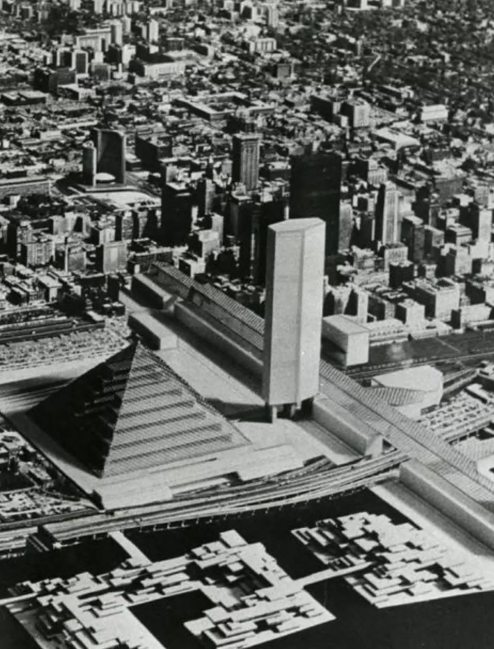
Almost at the same time the Metro Centre scheme was unveiled, another project for the interesting area was pre sented. In June 1968, Richard Buckmin ster Fuller and Shoji Sadao introduced “Project Toronto”, an alternative pro ject commissioned by The Toronto Tele gram and by CFTO-TV. Their project in sisted on the fact that Toronto needed a “special image”, a sort of statement that would solve the problem of the lack of distinction and unmemorable character that the city was facing. Like the Metro Centre proposal, also Project Toron to was a large-scale urban scheme. The architects introduced the idea of a “Galleria”, a long multi-functional pub lic space that connected the downtown and the lake. It would have been 914 meters long and there would have been a mini rail that facilitated the circula tion. The focus of the project was the realization of a third university with a technical and scientific vocation on the waterfront. It would have been hosted in a pyramid called “Crystal Pyramid”, with a square footprint of 243 meters each side and a height of 121 meters, that would have become an architectur al landmark. As in the project of Metro Centre, a “transmitting tower” was in cluded in the scheme59
131
Unbuilt projects: what Toronto could have been
fizzled the same year of its presentation and the criticism it received only antici pated the one that Metro Centre would receive in the very next future.
Project Toronto – Buckminster Fuller
The reasons behind the presentation of this project are not entirely clear. The proposal was published in July 1968 in the magazine Architecture Canada and raised questions among professionals about the costs, the actual availability of the interesting areas and the technical feasibility of the project. Project Toronto

132 Toronto

It is clear that OMA’s proposal for the Union Station revitalization did in clude not only a new vision for the train station itself but also an urban inter vention that highlights the lack of con nections between the Downtown and the waterfront. In this sense, we can say that Rem Koolhaas envisioned his

Koolhaas presented a vague and ambitious proposal but made clear his intentions. He divided the area into three parts: the Downtown, the railway, and the waterfront [Fig. 86].
The first four platforms on the north part are dedicated to GO trains, the platform on the south is for the Toron to Pearson Airport connection, while the two central ones are for VIA Rail.
133
In the waterfront area, the bus station is located in the same position as in the new development of CIBC Square. On the west part of the Air Canada Cen tre building, there are parking spaces and an area dedicated to the Toronto Convention Centre development [Fig. 87]. Rem Koolhaas’ vision for the area included building over the rail tracks a deck that goes from Lower Simcoe Street to Yonge Street. The deck hosts six towers and two sorts of in-door bridges that stretch themselves from the deck to the Lake Ontario shore.
Union Station – OMA
OMA’s plan was not chosen, and Zeidler Architects won the competition with their vision of the revitalization of the platform shed.
project with similar urban intentions to the Metro Centre proposal.
In 2001, a masterplan competition took place for the revitalization of Union Station, with LP Heritage and Union Station Consortium as clients. Among the participants, interesting is OMA’s proposal that sees Union Station as the centre that connects everything [Fig. 88].Rem
Unbuilt projects: what Toronto could have been
134 Toronto

Fig. 88: (on the right) OMA Union Station conceptdowntown connections.
Unbuilt projects: what Toronto could have been
Fig. 87: (above) OMA Union Station mockup - links.

59. Derek Flack. “10 Pro jects Toronto never built that would have trans formed the city forever”, BlogTO, October 31, ronto/.unbuilt_projects_in_tocity/2010/11/the_top_10_https://www.blogto.com/2020.
Fig. 85: (p.130) OMA Union Station project mockup.

135
Fig. 86: (on the left) OMA Union Station conceptareas.
Fig. 84: (p.128) 1968 Project Toronto by Buckminster Fuller.
136 Toronto

TORONTO’S
137
OFREAPPROPRIATIONTHEWATERFRONTAREA 3.5
until the beginning of the XXI century, that the waterfront area saw its huge growth.In2001, one year later the publica tion of the Toronto Waterfront Revital ization Task Force’s report, the City of Toronto, the Province of Ontario, and the Government of Canada, created Waterfront Toronto. This institution has a 25-year mandate to deliver a revital ized waterfront. The designated 800 hectares area, having roughly the same dimensions as Toronto’s downtown core (from Bathurst Street to Sher bourne Street and Front Street to Bloor Street), is enclosed between Dowling Avenue in the west and Coxwell Avenue in the east. The aim of Waterfront To ronto (formerly Toronto Waterfront Re vitalization Corporation) is to transform
During the last century, the area changed but not entirely. The proper waterfront part had few new build ings and urban interventions. It wasn’t
Fig. 89: Simcoe WaveDeck by WEST8.
Since the disposal of the rail yard in the 1960s, followed by the inter est of planners and architects in the area, and the consequent partial real ization of the Metro Centre scheme, the waterfront area underwent major urban renovations. Proving this, OMA’s project proposal for the Union Station revitalization did not only focus on the train station itself but extended its area of interest until Lake Ontario. The area, subjected to shoreline infilling, has been converted since the second half of the XX century and still ongoing, from industrial-, harbour- and railway func tions to a revitalized public space.
Waterfront Design Review District Boundaries 138 Toronto the “brownfield lands on the waterfront into sustainable mixed-use commun ities and dynamic public spaces”60 . The goal of Waterfront Toronto is to transform these abandoned spaces into vibrant spaces by emphasizing parks, 60. Waterfront Toronto ronto.ca.https://www.waterfronto,

Toronto’s reappropriation of the waterfront area

139
The Panel reviews all projects within the Waterfront Design Review District, which the larger Designated Waterfront Area established in the Toronto Waterfront Revitalization Act. See waterfrontoronto.ca for a more detailed view of the boundary. and public and cultural areas. In or der to achieve this goal, they embrace innovative approaches for sustainable developments. Another aim is to cre ate 40.000 new residential units, one million m3 of employment spaces and
Fig. 91: Revitalized central part of the waterfront.
changing, becoming a priceless area accessible to anyone, bringing positive benefits for the future generations to come.The waterfront renovation repre sents an important change for the city of Toronto and “seeks to place Toronto at the forefront of global cities in the 21st century”61
Fig. 90: (previous page) Waterfront Toronto Design Review District Bounda ries. The Panel reviews all projects within the Waterfront Design Review District, which lies within the larger Designated Wa terfront Area established in the Toronto Waterfront Revitalization Act.
» 62
To prove the positive impacts of this initiative is the fact that, In the period between 2001 and 2010, the revitaliza tion of the waterfront has contributed to the Canadian economy with almost 2 billion. The waterfront is currently
140 Toronto
62. Ibid
61. Waterfront Toronto ronto.ca.https://www.waterfronto,
300 hectares of green and public areas. Waterfront Toronto’s motto is to put people first in order to reconnect them with the waterfront.
« The revitalization of Toronto’s waterfront is the largest urban redevelopment project currently underway in North America, and it is one of the largest waterfront revitalization efforts ever undertaken in the world.

On October 05, 2021, we had in Toronto an interview with Leon Lai.
Yes, there is the project for the Ontario line for the subway and the addition of four new subway stations in the north on Line 1. In the project area, there is the extension of the streetcar line from Union Station towards Cherry Street on the est. Currently, the streetcar goes south to the waterfront but continues towards the west.
TORONTOWATERFRONTWITHINTERVIEW
The revitalization of the waterfront and the expansion of the PATH system to the other side of union station toward Lake Ontario.
Are there future public developments in the area worth integrating into our project?
Are there any future projects for infrastructure development in Toronto and especially in the project area?
The most important one, I would say, is the one on Bay Street. Waterfront Toronto is currently investigating the possibility of reducing the street in order to provide more space for pedestrians because, especially during the sports games, the area is not enough. We are exploring two possibilities: either enlarge one part of the sidewalk or add a central platform (like the Rambla in Barcelona). It would be interesting if you develop one of them and integrate it in your project.
141
Leon Lai is member of the Design Review Panel of Waterfront Toronto institution
How did the revitalization of the waterfront affect Union Station?
ININFLUENCEANDSTATIONUNIONITSTORONTO
4

63. ERA Architects, “Appen dix 4 - Heritage conserv ation district plan”, Union Station District Plan, (Era Architects, 2006), p.15.
145 introduction
For the development of this thesis, we decided to focus on the southern part of Toronto, where the Union Sta tion is located. Thus, going to include a new transportation system such as Hyperloop, whose purposes include minimizing waiting and travel time, the choice of the intervention area of this research by design would perfectly fit in the main multi-modal interchange zone of the Region.
vergent urban initiatives ”63
The station, indeed, stands on the boundary of what had been for years the division between the downtown and the former industrial area of the city, coinciding with the waterfront, which, following a process of deindustrializ ation, has turned out to be a vibrant place in constant evolution. The analyzed district paradoxically is an interchange point and, at the same time, has an urban conformation that implies a division between two major parts of the city, amplified by the presence of the rail corridor and the Gardiner Ex pressway. Therefore, the role of this part of the city and the opportunities and needs for improvement suggested by the location made the Union Station district an interesting case for the re search intervention.
Fig. 92: Union Station from Bay Street - Front Street intersection.
“The Union Station occupies a central position in Toronto’s urban landscape. Located between Toronto’s Financial District, Entertainment District, historic St. Lawrence Neighbourhood and the post-industrial waterfront, Union Station is sited as a civic landmark, a transpor tation gateway and a link between di-
146

organized on the Bremner Boulevard, having the Roger Centre at one extrem ity and the Scotiabank Arena and south ern entrance of the train station at the other.The area and the buildings adjacent to Union Station were included in the so-called Union Station Heritage Conservation District by the City Council in 2006. This act followed an in-depth study by ERA Architects to recognize the cultural value of the district, to en sure the preservation of architectural artifacts and to guarantee that new de velopment would take these pre-exist ing elements into account. This recog nition takes part in the Ontario Heritage Act. It aims at developing design guide lines to assist decision-making for de velopment proposals within the district and encourage the participation of local
STATIONCONSERVATIONHERITAGEDISTRICT 4.1
It presents itself as a vibrant and ever-changing area enclosing the southern part of the entertainment district with Toronto’s major stadiums – the Scotiabank Arena and the Rog ers Centre (formerly SkyDome) – the iconic CN Tower, the Aquarium, and the Roundhouse park. These buildings are
Fig. 93: View of the Union Station District from the CN Tower.
THE UNION
The Union Station district turns out to be a focal center for the city. From here, every business morning, a con densed flow of people is directed to wards the downtown, where all the workers take different directions. In the late afternoon the flow is reversed, hav ing all the Downtown workers directed to Union Station. These flows take place on several levels and systems: the street, the subway, and especially the PATH. Union Station represents in this network the core of all connections.
147
64. ERA Architects, “Appendix 4 - Heritage conservation district plan”, Union Station District Plan, (Era Architects, 2006), p.38.
stakeholders in promoting the preser vation character of the district.
The resulting district boundary “runs from Wellington on the north, to Yonge along the east, Lake Shore Boulevard/ Harbour Street on the south, and Sim coe Street to the rail corridor and Rees Street on the west. It is to be under stood comprehensively for its heritage character, urban design elements, and transportation context”64
surroundings a significant asset to To ronto’s urban and architectural history. The area clearly shows the juxtapos itions of the city’s urban developments, from the industrial heritage to the Beaux-arts urban configuration of the first years of 1900, which saw the union Station itself as a focal point, to the 1960s additions, the subsequent de-in dustrialization, and the actual densifica tion.Following, a use exclusively related to railroad and port activities (in the
Fig. 95: (on the right) The Union Station Heritage Conservation District boundaries.
Fig. 94: boundaries.EntrertainmentToronto’sDistrict
This Heritage Conservation District Plan makes the Union Station and its
The Union Station District 148
Toronto’s Entertainment District is a Downtown area located between Spa dina Avenue, University Avenue, Queen Street, and the Gardiner Expres sway. It groups the main entertainment building and activities and tourist attractions of the city. North of Front Street is more dedicated to theatres such as the Roy Thomson Hall and nightlife while the south, the sport and touristic zone, is characterized by larger blocks and buildings which beco me crowded with fans on days devoted to the big baseball, basketball, and hockey matches.
149 The Union Station Heritage Conservation District
« Union Station Heritage Conservation District boundary runs from Wellington on the north, to Yonge along the east, Lake Shore Boulevard/ Harbour Street on the south, and Simcoe Street to the rail corridor and Rees Street on the west. »
Fig. 96: Collage and pre cinct considerations among the Union Station Heritage Conservation District by ERA Architects in 2005.
in 1911 the Toronto Architect, John Lyle, was commissioned to create the area’s master plan. The plan was influ enced by the Beaux-Art style and the City Beautiful movement, placing Union Station as a focal and monumental point in the urban fabric. He defined a series of blocks big enough to accommodate large institutional buildings such as the Royal York Hotel (1929) and the Domin ion Public Building (1935) with the aim of creating a new monumental city.
With common goals, the area is also covered by the Waterfront Toronto in stitution, which is responsible for man aging the development of the entire waterfront area (see chapter 3.2).
From the outset, the station and the new elevated rail corridor (south of it) stood at the boundary between Down town and the increasingly developed railroad and industrial activities locat ed in the waterfront area. However, the connection between the two areas was provided by roadways perpendicular to Front Street and under the rail viaduct, allowing an unobstructed traffic flow into the city. Among these, Bay Street proved to be a fundamental connective element. The development of the area experienced a building boom in the mid-1950s, following the construction of the subway line, that changed the role of the station into an interchange hub. This formalized the city’s financial district with Union Station as its bound ary, redefining the ‘core’ of Toronto from Front to Queen Street. After the 1960s, the waterfront experienced a process of de-industrialization that made space for lots of parking lots to serve the emerging financial district. This process, together with the dispos
In more recent years, the water front area has undergone a continuous process of renewal and densification through the construction of large struc tures such as stadiums and numerous high-rise buildings, intended for resi dences and offices. In the investigated area, this process of development is controlled as a heritage conservation district. “With the view of preserving the architectural integrity of the district and creating an integrated public realm that recognizes the cultural significance of Union Station”65
The Union Station District 150
al of the railway yard, triggered a ser ies of large-scale urban development proposals, including the Metro Centre Project (see chapter 3). This proposal is representative for the history of plan ning in Toronto because its turbulent history increased a greater sensitivity towards heritage buildings.
mid of the XIX century, the shoreline was close to Front Street), the area experienced a considerable phase of urban planning.
65. Ibid. p.57.
u n i o 151 The Union Station Heritage Conservation District


Located on Front Street in the Herit age Conservation District, named after it, the Union Station opened in 1927 and is Canada’s finest example of a clas sical beaux-arts’ railway station. The Through station is Toronto’s main multimodal transportation hub. It serves the national and the commuter rail, the subway, the streetcar system, and the UP Express, a direct train transfer to the Pearson Airport, Canada’s busiest airport. The station hosts over 65 mil lion passengers per year and this num ber is predicted to be increased in the next years, thanks to the rail services expansion.
Fig. 97: Union Station main façade on Front Street.
153
THE UNION STATION
4.2
The history of Union Station is related to the necessity to link different railway socities.
Toward the end of the XIX century, despite several expansions, the station experienced overcrowding problems that intensified with the arrival of the Canadian Northern Railway in 1906,
Fig. 98: (below) The only known photograph of To ronto’s first Union Station, taken circa 1860s.
which had to share the station with Can adian Pacific and Grand Trunk. In those years, with the industrial development of the waterfront, a discussion about the possibility of separating the rail cor ridor level from the road system came out. This developed with several clash es between the railroad companies and the city. In 1904, a tragic event became an opportunity: the great fire of Toronto that destroyed large parts of the down town buildings opening up space near the railway lands. Therefore, the rail companies obtained the opportunity to build a new central railway terminal in exchange for raising the tracks to a higher level than the street level.
The Union Station District 154
The current Union Station was preceded by two other constructions, adapting to the waterfront expansion into Lake Ontario and the urban ne cessities of the city. The first [Fig. 98] was built in 1858 as a connecting place between three separate railways: the Great Western Railway, the Grand Trunk Railway and the Ontario, Sim coe & Huron66. This simple and wood en Through Station found a place near Front and Bay Street.
66. “Toronto Union Station,” Toronto Railway Historical Association (blog), accessed April 18, 2022, tion/.stations/toronto-union-stawww.trha.ca/trha/history/https://
Toronto’s First and Second Union Station
In 1873, as a result of the expan sion of the railway system, the wooden structure was replaced by a monu mental station on Front Street, between Simcoe and York. At the time of its opening, the station claimed the title of “the largest railway station in Canada”. It was characterized by a tall silhouette, with three domed towers on the south side and three arches over each track on the north. In contrast with the cur rent configuration, the main entrance faced south to the waterfront to facili tate the connection with the boat traffic. At that time, the lake shoreline was only few meters away from the façade [Fig. 99]. Following the subsequent land rec lamations e and development of new rail corridors and yards south of the station, it experienced an expansion of the platforms with an additional iron and glass train shed.

Fig. 99: 1873 photo taken looking towards the front façade of Union Station. Note that part of the harbour is visible in the foreground at left as it had not yet been filled in.

155 The Union Station
Fig. 100: A smoky scene in 1908 of Toronto Union sta tion showing the new yards that have developed south of the station. Courtesy of the City of Toronto Archives.
The main entrance was faced south to the waterfront to facilitate the connection with the boat traffic.

67. Brown Christopher, Still Standing: A Century of Urban Train Station Design (Indiana University Press, 2005), p. 91.
The Union Station District 156
Construction for the new Union Sta tion, commissioned by Canadian Pacific and Grand Trunk (soon to become Canadian National), began in 1914 and finished in 1927; in 1931 the old station was demolished. The present structure, designed by Ross & Macdonald, Hugh Jones, and John Lyle, is influenced by McKim’s Penn Station with a Canadian reinterpretation. The design features the classic XIX-century station setting: a neo-classical head-house with the main hall with all passengers’ facilities and a

This new construction, along with other buildings erected on Front Street,
functional train shed with arched truss es over the tracks67
The station’s façade (set on Front Street) is dominated by a central en trance colonnade of 22 Bedford lime stone Doric columns. The central Hall, which also includes the ticket lobby, takes inspiration from the Roman baths of Caracalla with a large coffered vaulted ceiling. The trains were reached with a depressed concourse, located under the elevated tracks, with separ ate flows for departures and arrivals.
The current Union Station
157 The Union Station
create a kind of a barrier to the water front and the industrial areas developed in the south thanks to the land reclam ation. The station façade, indeed, facing downtown and in which both entrances and exits are organized, contributed to reducing the relationship between the two parts of the city, obstructing even the view of the lake. Such a situation is comparable to what happened on a lar ger scale in Manhattan, where the rela tionship between the water and the city was practically nullified.
Fig. 101: A first page of the Toronto Daily Star, of August 11, 1927, showing the main façade of the Union Station the year of the inauguration.
Union Station as National Historic Site
Over the years, Union Station ex perienced a series of changes due to improvement and expansion of the rail system. This occurred especially in the concourse under the rail tracks. In 1965, the Ontario Government intro duced the commuter “GO” train ser vice and the Union Station became its main hub for the suburbs along the lake shore. During the second half of the 1900s, the station suffered several threats of demolition to replace it with a more modern and efficient structure.
mental scale to the classical details and building’s rational layout - and environ mental value because the main façade sets back from the street creating a sense of space and public importance and the design link between the station and the Dominion Building (located next to it) provides an important example of the urban planning characteristic of the beaux-art period68
Fig. 102: View of Front Street east from York Street with the Union station and Royal York Hotel in 1931.

The Union Station District 158
In 1968, the first Metro Centre pro posal (see chapter 3.4) sparked public outrage. The project was readapted several times to maintain the existing station but never saw the light of day in completeness. In the aftermath of these events, to the writing of the 1972 volume The Open Gate: Toronto Union Station by Mike Filey, and to the efforts of Mayor David Crombie, the station was designated in 1975 as a National Historic Site of Canada by the Govern ment of Canada. The station obtained this title due to its impact on its histor ical, architectural, and environmental values. Historical value for its role as a hub in the Canadian transportation history - Architectural value for its beaux-arts elements, from the monu
The station is composed by a great hall with passengers facilities on the north and a train shed over the tracks.
68. see ERA Architects, “Heritage Impact Assess ment: 141 Bay Street”, (Era Architects, 2018).
Fig. 103: (above) Union Station main hall in 2001.


159 The Union Station
Fig. 104: (below) Railway lands looking north to city core, between 1982 and 1988.
Fig. 105: Union Station main floorplan.
Fig. 106: Union Station North Elevation.
The north façade of the station (facing Front Street) is dominated by a central entrance colonnade of 22 Bedford lime-stone Doric columns. The central Hall, which also includes the ticket lobby, takes inspiration from the Roman baths of Caracalla with a large coffered vaulted ceiling.
Dig Down construction process before during construction after
69. NORR Architects, “Union Station Revital ization Project”, (Norr Architects, 2009).
In 2008, the need to expand and im prove the station as a transportation hub and restore the historical building made the Toronto City Council approve the Union Revitalization Plan. As de clared by the architectural firm NORR to which the work was awarded: “The key project objectives were to re-es tablish Union Station as the City’s pri mary multi-modal transportation hub, enhance the quality and capacity of the pedestrian movement to and from the station, rehabilitate the aging infra structure while restoring heritage fab ric and reinforcing Union Station as a
Union Station Concourse Column Replacement

164
The Union Station District
The Union Station Revitalization Plan (USRP)


The work began in 2010 and slowed down over the years by various factors; it will not probably be finished before 2023. The challenge has been to carry on the works while maintaining the operation of one of the busiest com
primary destination within the city”69
GREAT HALL
Fig. 109,110: (bottom) Main Floorplan and under ground plan schemes of Union Station organization and revitalization.

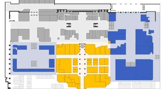
FRONT STREET
new link with the subway and the PATH system. Even the railway level is part of the redevelopment, with the addition of two new platforms, a new central and higher glass roof designed by Zeidler Architects (completed in 2015), and the restoration of the historic train shed by ERA architects.
RETAILMARKET TO STREETCARSUBWAY,PATH,
Fig. 107: (on the left, abo ve) Dig down construction process.
Accessibility features
The elevated train platforms are served by three lower concourses or ganized on two levels, the central one is for VIA trains (national trains), and the other two, the York and Bay concourses serve the commuters’ GO trains. The new Bay concourse, set on the eastern part, guarantees an underground con nection between the path and subway system and the Scotiabank Arena with the waterfront area.
GO RAIL YORK CONCOURSE
As described before, the Union Sta tion consists of two main elements: the Beaux-art head building and the plat forms
FRONT STREET
Fig. 108: (on the left, be low) Union Station concour se column replacement.
muter hubs in North America. With the aim of expanding the station capacity and triple the underground area in size, one of the most significant operations of the project has been to dig down the train concourses by several meters to create a new floorplan for commercial activities and transit connection, as the
Thearea.monumental body, with access es set on Front Street, is organized on five levels: the underground level pro vides the connection to the path sys tem, the subway, the streetcar stop, and the lower concourses; the ground level shows the main hall with ticket lobby, info point, lounges and connection to the train concourse; in the end, the up per three levels are used for offices by GO rail and VIA rail.
VIA
TO SCOTIABANKARENATOBOULEVARDBREMNER 165 The Union Station
FOOD COURT
GO RAIL BAY CONCOURSECONCOURSERAIL
Fig. 113: (next page) Union Station Cross Section.
The north façade of the station (facing Front Street) is dominated by a central entrance colonnade of 22 Bedford lime-stone Doric columns. The central Hall, which also includes the ticket lobby, takes inspiration from the Roman baths of Caracalla with a large coffered vaulted ceiling.
Fig. 111: (below) Union Station Train Shed Revital ization by Zeidler - Interior view.
Fig. 112: (on the right) Union Station Train Shed Revitalization by Zeidler.
The Union Station District 166

167 The Union Station


171 4.3
facts denote the urban evolution of the city over the years and many of them manifest interest from a national herit age perspective. Most of them are lo cated on the borders of the rail corridor – both north and south – or have a dir ect relationship with the area formerly occupied by the rail yard.
Fig. 114: Bremner Boule vard and Jurassic Park in the Union Station Conserva tion District.
As pointed out in the Union Station Heritage Conservation District, the area examined for the development of this thesis concentrates on a series of urban elements and buildings that, like the Union Station, prove to be relevant for Toronto from historical, cultural, and identity perspectives. These arti
AN OUTSTANDINGDISTRICT
1 32 3 7 4 95
173 6 8 1. CN Tower 2. Bremner Boulevard 3. Metro (MTCC)ConventionTorontoCentre 4. Roundhouse Park 5. Rogers Centre (former SkyDome) 6. Scotiabank Arena (former Air Canada Centre) 7. SkyWalk and UP Express + Union Centre Project 8. CIBC Square 9. Union Park THE UNION STATION DISTRICT Fig. 115: Union Station District Map with focused buildings.
Roundhouse Park is located south of the Bremner boulevard and was cre ated in 1997, together with the south ern expansion of the Metro Toronto Convention Centre. The park bases its development around the original Can adian Pacific locomotive roundhouse (1897) which currently hosts the Toron to Railway Historical Association and exhibitions. The park bases itself on the former railway yard as evidence of the past railway identity of the area.
Fig. 116: (below) First CN Tower design for the Metro Centre Proposal (1968).

Inaugurated in 1976, the iconic tower and Toronto’s main landmark was built to improve the telecommunication sig nal in the increasingly high and dense Downtown.Although the waterfront area has been densified since the end of the 2010s, the CN Tower still looks isolated and disconnected from its surround ings.The tower erected is different from the proposal of Metro Centre unveiled to the public in 1968 [fig. 116], but the goal stayed the same: the project wanted to leave a mark and make a statement, both nationally and internationally. The built structure consists of a high tripod and tapered reinforced concrete base (containing the stairwells and power and plumbing connections), which cul minates with a cylindric volume that includes the observation deck and a restaurant. The latter is surmounted by a continuous hexagonal concrete struc ture that ends with a second observa tion deck and a 102-m tall metal broad cast antenna. The construction works started in 1973 and finished three years later.The construction of the tower has become important also because in novative techniques were used to form and test concrete. With its 553 meters of height, the CN Tower resulted, at the time of its completion, the tallest free-standing structure in the world. The tower lost its status to the Burj Khalifa in Dubai in 2007.
CN Tower
Roundhouse Park
The Union Station District 174
Fig. 117: (on the right) Final design of CN Tower.
175 An outstanding district

The MTCC is a convention com plex located between Front Street and Bremner Boulevard, east of the CN tower. It is organized in two buildings separated by the rail corridor and con nected with an elevated tunnel (part of the PATH system). The north building, built in 1984 and designed by Architects Crang and Boak, includes large exhib ition areas and a hotel. As the CN Tower, its revised plan was part of the Metro Toronto proposal.
Bremner Boulevard
Fig. 118: (below) MTCC from Rod Robbie Bridge.
Metro Toronto Convention Centre (MTCC)
drum-shaped entrance hall. The latter, through the indoor bridge, guarantees access also to the northern part.
The Bremner Boulevard is a street that runs parallel and south to the railway corridor from Spadina Avenue to the Scotiabank Arena. It represents an important axis of the Entertainment District as it groups buildings such as the Rogers Center, the CN Tower, the MTCC, and the Scotiabank Arena. Prov ing its importance as a public space and connection between the two stadiums, the street becomes crowded with fans, heading to and from Union Station, during the days on which great sports marcher are hosted.
The southern building is part of a new large underground 1997 addition. It was designed by Bregman + Hamann Architects and is characterized by three underground levels with exhibition halls and meeting rooms, surmounted by a large, elliptical skylight and a
The Union Station District 176

Fig. 119: (above) Construc tion of the dome for the SkyDome.

Fig. 120: (below) Rogers Centre with open roof.
177
Rogers Centre
where the CNR Spadina Roundhouse was located. This pre-existence is still visible from the circular shape of the stadium.Thepeculiarity of this building lies in its retractable domed roof, designed by the architect Rod Robbie and structural engineer Michael Allen. It can be fully opened with arch-shaped elements that run on special tracks. The development of the stadium allowed the design of a large pedestrian area that groups it with the CN Tower development. This project showed an unusual fact for Toronto’s 1980s urban developments which relies on setting underground parking spaces instead of large openair parking lots for the stadium users. The Rogers Centre is also connected to Front Street and the MTCC through the so-called Rod Robbie pedestrian bridge.
An outstanding district
The Rogers Centre, formerly the SkyDome, is a multipurpose stadium, dedicated to baseball activities and built in 1989 on the former railway yard,

The area around the Scotiabank Arena has known a transition from large spaces dedicated as parking lots to a dense mixed-use neighborhood since the early 2000s. This boom of constructions has been incentivized by the proximity to the Union Station and the increasing demand of Toronto’s real estate.
During the 1990s, it was acquired by the Maple Leafs – the main hockey team of Toronto – with the intention of substitute the Maple Leaf Gardens stadium. The building was expanded and completely renovated in the inter iors. Subsequently, the western access was further modified and implemented with the PATH system that allows the connection to the southern part of the waterfront. The arena still incorpor ates two façades of the original Toron to Postal Delivery Building. Following the union station revitalization plan, it

The Union Station District 178
is interposed as a connecting element between the CIBC square and therefore the GO bus terminal, the Bay concourse of the station, and the subway.
Fig. 122: (below) Toronto Postal Delivery Service building before the transi tion to an arena.
Scotiabank arena
The Scotiabank Arena, formerly the Air Canada Centre, is located on Bay Street, on the southern side of the Union Station, from which it can be reached indoors through the Bay Con course. Initially, it was not conceived as a multi-purpose arena but, when it was built in 1941, it hosted the Toronto Post al Delivery services [fig. 122]. Designed by Charles Dolphin, the building repre sents the International Style with strip windows and Canadian Deco influences.
Fig. 121: (above) Scotia bank arena from Bremner Boulevard.

An outstanding district
architectural detailing to Union Station, acted as a terminus for horse-drawn carts delivering goods to and from Union Station. The central area of the Skywalk hosts the UP Express service terminal, designed by Zeidler Archi tects. UP Express is a rail service that, since 2015, directly connects the station with Terminal 1 of Pearson airport in 40 minutes. The building runs parallel to Front Street until Simcoe Street, where it is linked through an elevated tunnel over the rail tracks with the Southcore Financial District, the CN Tower and Ripley’s Aquarium.

SkyWalk and UP Express + Union Centre Project
The SkyWalk will be affected by the construction of the 171 Front Street
179
Intending to connect the Union Sta tion to the Rogers Centre with a pre dominantly indoor connection, the City Council decided in 1989 to build the SkyWalk. This building consists main ly of a large glazed passageway, long almost 160 meters, and enclosed by a semi-circular arched roof reminiscent of early-century European pedestrian areas [fig. 123]. It is part of the PATH system and starts at the western wing of Union Station including the Canadian National Express Building. The latter, built in 1929 with similar limestone and
Fig. 123: SkyWalk semi-cir cular arched roof.
The Union Station District 180 West Tower [fig. 125]. The project was filed in 2020 by Bjarke Ingels Group and includes a 54-story office tower placed above the current structure. The project doesn’t only aim at hosting new office spaces but also at improving the usage of Station Street and increase pedes trian use, triggered by the completion
Union Centre will bring green spaces to a new level in the city.

Fig. 125: (right) Union Centre development and adapted SkyWalk fro Roundhouse Park.
Fig. 124: (left) Union Centre top view.
of the UP Express terminal. Most of the SkyWalk structure will be removed and replaced with a new design but the route will be maintained. The top of the tower is characterized by terra ces composed of modular rectangular elements, providing a staggered green roof on multiple levels [fig. 124].
181 An outstanding district

Fig. 126: (below) CIBC Square first tower at 81 Bay St., now complete.

Fig. 127: (on the right) CIBC Square and Union Station (Bay Street part) from Front Street.
126]. The elevated park is supposed to be finished in 2022. The south building hosts in its two-story podium the new Union Station Bus Terminal (USBT) as a substitute for the former one located in area on which the north tower will rise. The terminal is characterized by an indoor connection with Scotiabank Arena and Union Station that runs par allel to the rail corridor. The two sky scrapers, designed by WilkinsonEyre and Adamson Associates, are already becoming new landmarks for the city and are characterized by glass façade with rhomboid patterns..
The Union Station District 182
CIBC Square is a new office develop ment that will host the Canadian Imper ial Bank of Commerce (CIBC) headquar ters. The development is composed of two 49-story towers located on Bay Street, east of the Union Station, at the two opposite sides of the rail corridor. Over the railway, the two buildings are linked with an elevated privately-owned public green space. The construction works were organized in two phases and the northern tower is currently under construction, while the south ern one was completed in 2021 [fig.
CIBC Square
CIBC Square is located next to Union Station and it incorporates the Union Station Bus Terminal as well as part of the PATH system.
183 An outstanding district

Fig. 129: (on the right) Union Park inserted in the Toronto Skyline.
The Union Station District 184
Union Park
The Union Park is a proposal for a future development located north of the Rogers Centre. Designed by Pelli Clarke and Associates, it consists of a residential tower and two office sky scrapers, set on a public podium with a park and retail facilities, located north of theSimilarrail. to CIBC Square, the project aims at creating a public space above the railway corridor [fig. 128]. There fore, the master plan also aims at join ing two crucial parts of Toronto’s down town through an elevated public park that will be connected to the future Rail Deck Park development (currently is just a Thisproposal).factassumes a possible future extension developed above the rail cor ridor westward.
New iconic towers will be added to Toronto’s skyline, while implementing green spaces in a dense area of the city.
Fig. 128: (below) Union Park public space above the rail corridor.

185 An outstanding district


The survey visit was organized ac cording to the users’ experience in the existing intermodal hub by conducting hypothetical routes of connection be tween modes of transportation and with the city. The site visits, divided in different days, took place during a peak time (from 8:00 to 9:30 am), and in the early afternoon (3:00 pm), when the presence of people is reduced. The pur pose of this investigation was to under stand the functioning of the hub, the differences with the European system, the problems, and the possible oppor tunities for intervention. This survey process has been fundamental for the purposes of the research and subse quent design process.
187 4.4
The first thing we understood about this hub is its sprawl within the district and the walking distance between each mode of transportation; the Bus Ter minal and the UP Express, for example, are more than 600 meters apart. In addition, points of interest and system terminals are sometimes located in physically separate buildings and con nected by air-conditioned (elevated or underground) linear walkways that are part of the PATH. Therefore, the station appears disconnected despite the new interventions, that seem to be more aimed at increasing the commercial scale of the environment. It must be said, however, that some of the works were still in progress, so it was not possible to get effective feedback on its final operation.
Fig. 130: Toronto Union Sta tion rail corridor from the PATH (SkyWalk part).
ON-SITE EXPERIENCE
188
A
SITE VISIT: HUBTRANSPORTATIONFRAGMENTED
189
picture not part of the route picture part of the route route at level route below level route above level
155 156 157 158 159 160
132133 135 134 136 137 139138 140-141142 143 144 145 146147 148 149 150 151 152 153 154
The Union Station District 192
Fig. 132: Atrium of connection between the Subway and the Union Station. Part of the NORR revitalization.

experience
On-site
193
Fig. 133: Union Station main entrance to the underground concourse. The main façade shows entrances to two different levels, the one of the main Hall and the one of the concourses, located 3,50 meters underground.

The Union Station District 194
Fig. 134: York entrance of Union Station.

On-site
experience
195
New underground level by NORR architects to directly connect the subway and the train concourse.
Fig. 135: Bay concourse.

The Union Station District 196
Fig. 136: Union Station Hall. The ticket offices are visible on the right side of the Hall.

197
Fig. 137: Union Station Hall - info point detail.

experience
On-site
The Union Station District 198
Fig. 138: Access to VIA Rail Concourse from the Great Hall.

experience
199
Fig. 139: VIA Rail Concourse. Accesses to national VIA Rail trains.
On-site

Fig. 140: York concourse. The revitalized concourse is organized on two levels with a food court in the new underground level.
The Union Station District 200

201
Fig. 141: York Concourse - access to food court.

experience
On-site
The Union Station District 202
Fig. 142: Union Station food court.

203
experience
Fig. 143: Access to the commuter platforms. The staircase are closed due to the harsh winter weather.
On-site

Fig. 144: GO train platform under the Zeidler Architecture glass roof. Contrary from the majority of stations, here each train is served by two platforms for managing accesses and exits.
The Union Station District 204
Fig. 145: Original train canopy revitalized by ERA Architects.

On-site experience
205
Fig. 146: Bay concourse access to Scotiabank Arena.
The Union Station District 206

Fig. 147: Scotiabank Arena Atrium (Union Station side).
experience
207
The corridor is part of the PATH and directly connects the station with the new Bus Terminal in the CIBC Square through an elevated tunnel.
On-site

The terminal is part of the CIBC Square South tower podium and is organized on two levels.

The Union Station District 208
Fig. 148: GO Buses terminal.
209
On-site experience
Fig. 149: Elevated tunnel on Bay street. The tunnel connects the Scotiabank Arena and Union Station with the Bus terminal.

Fig. 150: South entrance of Union Station from Jurassic Park.
The Union Station District 210

211
On-site experience
Fig. 151: South entrance of Union Station. The façade hides the small entrance which is not able to manage people flows during peak times.

Fig. 152: PATH section inside the Scotiabank Arena.
The Union Station District 212

213
On-site
experience
Fig. 153: PATH elevated tunnel below Gardiner Expressway. On the southern side of the rail corridor the PATH is completely organized in elevated tunnels between buildings.

Fig. 154: PATH section in Telus Tower. The PATH provides direct access to the building foyers.
The Union Station District 214

215
On-site experience
Fig. 155: Rail corridor view from the PATH section of the SkyWalk.

Fig. 156: Elevated connections above the rail corridor.
The Union Station District 216

On-site experience
217
Fig. 157: Skywalk access from the Union Station. The Skywalk is part of the PATH and help to connect the Union Station with the touristic area of the CN Tower.

The Union Station District 218
Fig. 158: SkyWalk with UP Express access. The UP Express provides a direct train link with Pearson Airport.

On-site
Fig. 159: UP Express platform by Zeidler Architecture.

219
experience
The Union Station District 220
Fig. 160: Rail corridor - view towards south.

Fig. 161: The Union Station area from the CN Tower. The skyscraper dense area provides privileged point of views of the city.

On-site
221
experience
222
CHALLENGESNEWISSUESIMPRESSIONS,AND
223
the south entrance of Union Station is hidden behind buildings and in a dead-end road
car traffic on Bremner Boulevard (the street that connects the two stadiums)
Fig. 162: Scotiabank Arena and Bremner Boulevard. Bremner Boulevard is the street that connects the two stadiums (Scotiabank Arena and Rogers Centre), and it is used both by cars and pedestrians. The road becomes problematic, especially when the games take place because significant flows of people exit from the stadiums and are directed in the same direction towards Union Station. The street in front of Scotiabank Arena is particularly problematic because it also provides access to Union Station, whose entrance is completely hidden and not visible from the Boulevard.
The Union Station District 224

225
On-site
undergroundentranceparking
experience
the space is shared by pedestrians and cars
Fig. 163: Union Station south entrance. Seen from Maple Leaf Square, it is covered by a massive sculpture. Pedestrians and cars share the space, and garage entrances are placed on the façade of the buildings. In addition, the flows of people directed to Union Station collide with the ones headed to Scotiabank Arena.

no division of flows between people directed to Union Station and to Scotiabank Arena
the south entrance of Union Station is completely hidden behind the sculpture
no view of the outside since the construction of the shed in 2015
The Union Station District 226
Fig. 164: Union Station revitalization by Zeidler Architecture. The platform area appears to be very dark even after the construction of the new shed. The renders promised a privileged view of the city and the surrounding skyscrapers, but in reality, the glass doesn’t permit high transparency; therefore, the outside is not visible.

On-site
Fig. 165: Train platforms. Access to the platforms is provided with an indoor staircase that connects it to the concourse level below. However, the staircase has to be air controlled because of the extreme weather in Toronto during the winter. Therefore, the platforms are narrow because they are not used as a place to wait for the train.

platforms are very narrow
air-controlledstaircases
experience
227
Fig. 166: Scotiabank Arena during games. Scotiabank Arena represents an essential point in the Intermodal Hub network. Here, the stadium entrance, the access to Union Station, and the PATH leading to the Bus Terminal can be found. Especially during games, it is common that the three different flows bump into each other because they share the same corridor.

stadium entrance
GO Bus Terminal
UnionentranceStation
The Union Station District 228
Fig. 167: Elevated connections. Bridges connect the two parts of the city through “linear” connections. The rail corridor could be covered in order to provide connections through “surfaces”.

229
On-site
Downtown - waterfront connection provided by linear bridges
experience
Fig. 168: Bay Street and Front Street intersection. The sidewalks that connect the Downtown to the Waterfront are too narrow for their needs. They are used both by people going to the waterfront and by the commuters of Union Station.

The Union Station District 230
the sidewalk is too narrow for serving both Union Station and Bay Street (connection downtown - waterfront)
York Street presents itself as a very busy street
231
On-site
experience
Fig. 169: York Street and Front Street intersection. The intersection between York Street and Front Street is a busy road as well. The streets are important axes that connect the Downtown and the Waterfront.

Bay Street has several lanes that increase car traffic

232
Fig. 170: Green areas and public spaces in the Union Station surroundings. On the one hand, the Downtown presents a lack of open-air public spaces, especially green areas, in contrast to the high density of skyscrapers. On the other hand, the waterfront has many parks on the blocks facing Lake Ontario. Next to Union Station, there is only Roundhouse Park, but it has a cultural and touristic function more than a public park function. In addition, the Love Park project, currently under construction, adds new green spaces in the buffer zone between the Downtown and the proper waterfront, an area that suffers the lack of them.
bikes share the space with cars Union Station District
the parking area will be replaced with a new tower, adding another building to an already dense area
The
experience
flows of people directed to the waterfront have to cross busy streets and pass under Gardiner Expressway
Gardiner Expressway’s structure present itself as very damaged

On-site
Fig. 171: Deterioration of Gardiner Expressway.
The structure of Gardiner Expressway appears to be very deteriorated, making the path that connects the Downtown to the Waterfront dangerous and unwelcoming.
233
Fig. 172: Reaching the lakeshore passing below the highway. The path connecting the Downtown to the Waterfront is composed of a sidewalk following and crossing busy streets. It is also characterized by the Gardiner Expressway that passes above it, creating, with the rail corridor, a second barrier between the two parts of the city. In addition, the only green spaces usable are located on the lakeshore.

Gardiner Expressway represents a division between the city and its waterfront
The Union Station District 234
accessible green areas only on the lakeshore
Torontonians have to walk through hectic streets and below the highway to reach the waterfront
experience
Fig. 173: Roundhouse Park and its cultural function. The Roundhouse Park is located next to the rail corridor, where the rail yard was. Today, its function is more of a cultural and touristic attraction instead of a city park. In fact, during the site visits, it was always empty.
Roundhouse park is not used by Torontonians as a public and meeting place, but is only a transit area.

235
On-site
Fig. 174: View from the south exit of Union Station. Once the travelers exit the station on the south part, they find themselves in a square surrounded by buildings where the directions of where to go are not clear. The view of the lake and of the main streets is blocked by the skyscrapers and contributes to a sense of disorientation in the visitor.
The Union Station District 236

CIBC Square
Front160StreetWest 237 On-site experience
Fig. 175: The district keeps evolving. From the top of CN Tower it is evident that the area is in continuous development and new buildings are currently under construction. In addition, other development projects are being proposed.
Union(proposal)Centre

outdoorSquarePecautspaceforevents
OlympicPark
HTO Park Ontario and Canada
LoveSquaresPark The Union Station District 238
On the other hand, the waterfront has many parks on the blocks facing Lake Ontario. Next to Union Station, there is only Roundhouse Park, but it has a cultural and touristic function more than a public park function. In addition, the Love Park project, currently under construction, adds new green spaces in the buffer zone between the Downtown and the proper waterfront, an area that suffers the lack of them.
RoundhousePark
Fig. 176: Green areas and public spaces in the Union Station surroundings. On the one hand, the Downtown presents a lack of open-air public spaces, especially green areas, in contrast to the high density of skyscrapers.

AnnParkTindal
DominionCentre
Berczy Park David
SqaureHarbourPark
700m 350m
Ferry terminal
Fig. 177: Union Station interchange hub distances.
GO bus terminal streetcar subway
239 On-site experience
The Union Station transport hub presents itself as a diffused hub, with means of transportation such as the GO Bus Terminal, the UP Express, the streetcar and the subway in a distance radius of 350 meters from Union Station, while the Ferry terminal is located 700 meters away.
Union Station
UP Express
REPORTPROJECTDESIGN
5

245
Fig. 178: Aerial view of To ronto at sunset.
After a research and documentation phase, we started the project phase by studying the possible ways of introdu cing the hyperloop system in the North American context, starting from the Canadian city of Toronto.
This implied choosing the hyperloop routes, studying the effects and im pacts that this new technology would have on the city and on a global level and, deciding the best area for the pro ject development.
TERRITORIAL FOCUS 5.1
hyperloopairplanetraincar
TORONTO - DETROIT hyperloopairplanetraincar
TORONTO - NY hyperloopairplanetraincar
TORONTO - MONTREAL hyperloopairplanetraincar
Toronto - Ottawa (405 km) hyperloopairplanetraincar
TORONTO - MONTREAL hyperloopairplanetraincar
TORONTO - BUFFALO
TORONTO - DETROIT cartrainairplanehyperloop

28min 3h50min4h15min4h36min 0 kg CO2 137 kg CO2 22,8 kg CO250,5 kg CO2
29min 3h40min4h40min4h30min 0 kg CO2 45 kg CO2 24,3 kg CO253,8 kg CO2
cartrainairplanehyperloop
Toronto - Montréal (542 km) hyperloopairplanetraincar
Toronto - Detroit (380 km)
Travel time and emissions
TORONTO - QUEBEC hyperloopairplanetraincar
TORONTO - NY
cartrainairplanehyperloop
TORONTO - OTTAWA hyperloopairplanetraincar
40min 4h25min5h10min5h 0 kg CO2 56 kg CO2 32,5 kg CO2 72,1 kg CO2

42min 2h05min 12h50min 8h20min
These calculations have been made with the starting point in Toronto Union Station and the arrival was in the central station of the connected city. For the airplane, the calculation started with the central station as well, but the travel time to reach the airport (light grey) and the waiting time before the flight (dark grey) have been added to the calculation. The flight time has been taken from Google Flights by choosing Air Canada (with only the exception of Toronto - New York City when Flair Airlines was selected) and the most frequent solution. Google Flights has been used also for the CO2 direct emissions calculation.
2 No direct flight; the two cities are too close.
4 Until Niagara Falls, then the next train is from Amtrak Niagara Falls Station
Toronto - Québec City (803 km) hyperloopairplanetraincar
TORONTO - DETROIThyperloopairplanetraincar
52min 5h10min 8h30min 0 kg CO2 32,5 kg CO2 109,9 kg CO2
TORONTO - BUFFALO hyperloopairplanetraincar
Design Project Report 248
hyperloopairplanetraincar
TORONTO - NY cartrainairplanehyperloop
Toronto - Chicago (827 km)hyperloopairplanetraincar
Toronto - Buffalo (161 km) 0 kg CO2
3 The calculation has been made until Niagara Falls.
1 No rail connection for this route.
TORONTO - CHICAGO cartrainairplanehyperloop23 12min 2h2h12min 0 kg CO29,60 kg 21,4CO2kg CO2
TORONTO - CHICAGO cartrainairplanehyperloop1
The calculations of the total travel time for trains and cars have been with Google Maps, while for hyperloop the average travel time proposed by Virgin Hyperloop was taken. Hyperloop doesn’t have direct CO2 emissions, while for cars and trains we took two coefficients from the website of Co2connect and then multiplied them for the distances. The coefficient (calculated for a single passenger) was for cars 0,133 kg and the trains 0,06 kg.
TORONTO - NY hyperloopairplanetraincar
TORONTO - DETROIT
TORONTO - BUFFALO cartrainairplanehyperloop4
TORONTO - QUEBEC hyperloopairplanetraincar
54min 4h50min 10h 8h 0 kg CO2 56 kg CO2 48,2 kg CO2 108,6 kg CO2
Toronto - New York City (767 km) hyperloopairplanetraincar
TORONTO - MONTREAL hyperloopairplanetraincar hyperloopairplanetraincar
0 kg CO2 62 kg CO2 51,4 kg CO2 102 kg CO2
Fig. 180: Comparison of travel time and CO2 direct emissions of the second phase routes.
249 Territorial Focus
Fig. 179: (previous page)
In 2022, one of the main problems connected to transportation is the ten dency toward global cities and therefore the need of improving long-distance connections, both for business and lei sure purposes. In this sense, Canada would be the perfect application for the hyperloop system because of its huge territorial extension and long distances between major cities. In fact, currently, the most convenient mean of transpor tation in Canada is the airplane, especial ly to travel from one coast to the other. Frequently used for travelling medium distances, as from Toronto to Montréal, is the car, while the train stays as the last choice when it comes to travel long and medium distances, mainly due to the lack of high-speed rail that forces the passengers to long hours of train travel for distances that are easily cov ered by a one-hour flight. Another key aspect when it comes to transportation is pollution and energy consumption. We calculated and compared, for the same routes, (phase 1 and phase 2) the
For introducing the hyperloop sys tem in North America, we thought of a three-step development. We thought of Toronto as the central point of the system and during the first phase, that would partially follow the suggested route described in chapter 1.3 (Toron to-Ottawa-Montréal), the city would connect Detroit to Ottawa and Montréal through a hyperloop corridor. We have chosen to connect firstly these cities because there is a high interest in the Toronto-Montréal route mainly because of business and commuter reasons. We maintained the Ottawa stop in this phase because we believe it is important to connect the capital of Canada in an early phase of the hyperloop develop ment in order to improve exchange and city growth. We added the American city of Detroit to the first hyperloop route because, as the founders of the TransPod Company confirmed, Sebas tien Gendron and Ryan Janzen, there is interest in connecting Canadian and American cities through this innova tive transportation system. During the second phase of the construction of the hyperloop system network in North America, Toronto stands out as the cen tre of the entire system. While the first phase route will be expanded in the North-East part with the connection to Québec City and in the South-West with the connection to Chicago, a third con nection will be introduced starting from Toronto and arriving in New York City, passing through Buffalo. Expanding the system and connecting important cities
Hyperloop as a promising answer to global problems
Hyperloop routes propos als divided in two phases and later expansion of the network. First phase is represented in blue, second phase in yellow. On the left there is the comparison of travel time and CO2 direct emissions of the first phase routes.
is essential in order to contribute to the growth of Toronto as the city is current ly growing really fast and proposing it self as one of the most important North American cities. After the first two phases, we predict an expansion of the system from New York City towards the East Coast, from Chicago to the centre of the U.S. and the West Coast and from Toronto to Winnipeg and Calgary until Vancouver.
Introducing a new transportation system
2 min frequence
10 tonnes/pod
With the climate change crisis and the tendency toward global cities, long-distance travel and pollution are a few of the currently most discussed topics. The hyperloop system could be a valid solution to today’s problems, as said before, because it doesn’t have direct CO2 emissions that would have a negative impact on the environment, especially when the infrastructure passes through the cities. It works with less energy that electric trains and would be powered by renewable ener gies, including self-sustainable solar
1000 km/h
important events and attract people from other regions
el emissions, making it the best option from the ecological footprint point of view. We estimated the direct emis sions for airplanes, cars, and trains70 , and every one of them emits a sub stantial amount of CO2, being cars and airplanes the worst. By comparing the direct emissions and the total amount of time needed to travel from one city to another, we wanted to prove the fact that the hyperloop system would have a positive impact on the environment with no direct emissions and would be a better solution for the individual trav eler because of reduced travel times.
A pod can carry up to 50 passengers
high frequentspeedtravel
50 pax/pod
A pod can carry up to 10 tonnes of freightsensitive
ENVIRONMENTAL TOPICS
CITY GROWTH pollution
resistant to earthquakes immune to bad weather sustainabilityconditionsless invasive in the landscape
Maximum speed up to1000 km/h
A departure every 2 minutes
climate change long distance connections tendency towards global cities
Design Project Report 250
HYPERLOOP SYSTEM
direct CO2 emissions and the travel time requested by traditional transportation means, such as car, train and plane, with the one needed by the hyperloop system. We did the calculation by start ing and ending the travel in the main train station of the cities. This obliged us in adding the travel time requested to reach the airports, located on the periphery of the cities, to the calcula tion. As a result, the total travel time needed for the Toronto-Montréal route by airplane is four times longer than the flight itself. This made it obvious that, even if the airplane could seem a valu able option for travelling long distan ces, the location of the airport implies longer travel times. On the contrary, with the hyperloop system, whose sta tion can be placed in more strategic places, you would only have to consider the actual travel time of the Pod that, in the case of the Toronto-Montréal route would be 40 minutes (one-seventh of the four hours and twenty-five minutes requested by the total airplane travel). Hyperloop would not only cut the travel time to a 30–45 minutes travel period but would also have no direct fossil-fu
city interconnectivity attracts investors the construction costs less than high speed’s one new job opportunities and commuters from other regions tourism cities are closer, more exchangetransportation ofcangoodshost
Territorial Focus
The introduction of the hyperloop system in Toronto would contribute enormously to the city’s growth by at tracting new investors, setting itself as a city that embraces pioneer pro jects, providing new job opportunities and attracting commuters from other regions. By reducing the time spent travelling, cities feel closer to the other and therefore they gain more exchange
in terms of business, goods, tourists, and culture. Toronto would be able to attract and host important events that help the city become a crucial one on the global level.
251
The first area we took as a candidate for hosting the new hyperloop station is located on the rail corridor between the two buildings of the Metro Convention Centre. To be less invasive as possible, the infrastructure would follow the railroad and the station would be built above it, in a strategic position between the Downtown and the Entertainment District. In fact, it would have a dir ect connection with the entertainment area and the Metro Convention Cen tre, implying a renovation intervention on the latter, but would fail in having a direct and quick connection with all the means of transportation located inside the Union Station building. The location of this proposal would have been very interesting, but the lack of smooth con nections to the city’s public transporta tion made us favour other spots.
70. As mentioned before in chapter 3, currently Canada doesn’t have electric trains but diesel ones instead.
The second area that interested us is the one occupying partially the Roundhouse Park. We saw potential in this spot because of the proximity to the Entertainment District and above all the relationship that it could have cre ated with the former rail yard area. As a matter of fact, the Roundhouse Park arises where once there was the train’s rail yard and the roundhouse building, that today hosts the Toronto Railway Museum, is the remaining evidence of
Choosing the right area of intervention
Fig. 181: (above) TransPod system characteristics.
Fig. 182: (below) Hyperloop effects on the city and eco nomy.
power, making it a sustainable mean of transportation. According to TransPod, the Pod is immune to weather effects71 since it travels in enclosed tubes and therefore the likelihood of trip cancel lation due to weather is low compared to other transportation systems such as airplanes72. The infrastructure can also be less invasive on the landscape because it can be placed underground or, when it is above ground, it is less problematic for land concessions be cause the pillars would only occupy a small portion of land. The high speed at which the Pod travels (1000 km/h) and its high-frequency departure (one Pod every 2 minutes) introduce hyperloop as the most desirable option when it comes to long-distance travel because it brings cities closer one to the other and goes well with today’s tendency to wards connecting global cities. From an economical point of view, its construc tion would be less expensive than the one of high-speed rail. In fact, in the In itial Order of Magnitude Estimate (OME) study published by TransPod in July 2017, the company explained that the construction of a TransPod system be tween Toronto and Windsor would cost half the budget needed for introducing high-speed rail in the same segment73
71. TransPod in Alberta. Summary of study on the implementation of a Trans Pod Line from Calgary to Edmonton, June 2021, p. 6.
72. TransPod in Alberta. Summary of study on the implementation of a Trans Pod Line from Calgary to Edmonton, June 2021, p. 16.
73. Initial Order of Magni tude Analysis for TransPod Hyperloop System Infra structure. Preliminary Basis of Design, July 2017, pag. 23.
AREA 05AREA 01AREA 02 AREA 03 AREA 04 Design Project Report 252
In area number 3, the new infra structure would follow the Gardiner Expressway as well. It would be closer to the Union Station and a direct con nection with it would be possible by connecting the hyperloop station to the PATH system that passes through the Scotiabank Arena. Due to its position, the station would be in an intermedi ate position between Downtown and Waterfront, close to Union Station, the Ferry Terminal and redeveloped area of the waterfront. This location is one of the most strategic ones but the land plot available is very small and the sta tion would be surrounded by skyscrap ers making it difficult to find it in such a dense
Theneighborhood. second-last area is located
what that area was seventy years ago. Placing here the new station would make the architectural building very visible because it wouldn’t be hidden and surrounded by skyscrapers. The infrastructure would follow the Gar diner Expressway but there wouldn’t be a direct connection with the Union Station, the UP Express, the bus sta tion and the subway station therefore, the lack of a compact intermodal hub would affect negatively the uses of the hyperloop system because passengers would find themselves at a ten min utes-walk and 1 km distant from the Union Station, a crucial point in the city for the public transportation system (it is the southern subway stop and the closest to the waterfront area).

Railway corridor
Fig. 183: (above) Site area proposals and freight sta tion location.
Territorial Focus
above the rail tracks and behind the his torical building of Union Station, making this spot the closest to all the public infrastructures that meet at the Union Station stop. We chose this area as the most suitable for the development of the new hyperloop station because it would enable us to create a well-con nected intermodal hub: we have the chance of adding a new transportation system but also of improving the ex isting connections into one well-func tioning hub. The infrastructure would follow the rail corridor, while the station would be placed in a strategic location between the Downtown and the water front area. The proximity to Bay Street would improve a direct connection, also through public transportation, with the
Fig. 184: (next page) Satel lite image of the Union Sta tion area in Toronto.
253
Gardiner Expressway
FREIGHT STATION
The last area is the one located
on the east, where the Gardiner Ex pressway and the railroad run next to each other. Therefore, the hyperloop tubes can follow one or the other infra structure and the barriers that both of them create can be overrun by one ped estrian connection. On the one hand, the station would be close to a currently under development area which makes it interesting for new opportunities and close to Union Station. On the other hand, the station would be far from the Entertainment District and the redevel oped waterfront area. On top of that, only a small plot of land would be avail able, making it difficult creating a good and welcoming connection between the street level and the elevated station.

Design Project Report 254
Keeping in mind all the perks and the challenges of the area we chose, we developed the project around three main themes that reflect some of the topics that we encountered during the analysis of Toronto: public realm, recon nection of the downtown to the water front and the multilayer aspect of the city.
In addition to the passenger station, we also hypothesized a freight station in the east, near Port Lands, in the portion between the rails and the Gardiner Expressway that is currently partially occupied by a rail yard. Pla cing here the hyperloop freight station makes sense because the goods can be exchanged with the trains during the intermediate phase when freight transportation is not entirely made by hyperloop and does not interfere with the passenger’s transportation.
Ferry Terminal that is placed at the end of the street. The new station would create a bridge in an area that is very busy, providing the citizens with other routes to cross the rail corridor.

255 Territorial Focus

SubwaySubway expansion (Ontario line) StreetcarStreetcar (underground) Streetcar (future expansion) FerryRail line Path (underground) Path
HighLowTransportationGardiner(elevated)Expresswayhubsvegetationvegetation
After an accurate analysis part, both researching and on-site visit (described in chapter 4), we started the project de sign phase by mapping all the means of transportation. It is clear that the site area is an important interchange point where the rail infrastructure (GO trains, VIA Rail and UP Express) meets the GO Bus terminal, the subway (Line 1 Yonge-University), the streetcar and the taxicabs and RideShares [Fig. 186].
Since the railway corridor creates a barrier between the Downtown and the waterfront area, we decided to create a large-scale pedestrian bridge that connects these two parts and is placed between two elevated parks, where the East one is currently under construc tion, while the West one is a proposal [Fig. 187]. This new level will host the hyperloop infrastructure, that will fol
URBAN FOCUS 5.2
Fig. 185: Infrastructure and transportation systems in Toronto.
low the rail corridor, and the new sta tion [Fig. 188]. Locating the Hyperloop station next to the Union Station build ing places the new station as the cen tral point that connects all the existing means of transportation [Fig. 189]. The elevated deck is reachable by sets of staircases, ramps, escalators and ele vators placed, on the downtown and the waterfront sides, on the sidewalk of every street that passed beneath the project. We also incorporated part of the PATH system that was crossing our project site with two bridges and extended the system by creating a new covered connection for the USBT [Fig. 190]. After that, we covered the parts of the PATH with walkable green hills in order to have a continuous outdoor public space without any interruption [Fig. 191].
257
Fig. 188: Step 3. Introduction of the hyper loop system and footprint of the new station.
Fig. 187: Step 2. Covering the rail corridor with a deck located be tween two elevated urban parks. The deck is a con nection between the two parts of the city separated from the rail way.


Design Project Report 258
Fig. 186: Step 1. Transportation systems in the site area.
Fig. 189: Step 4. The new station will be located in a central position between all existing means of transport.


Fig. 191: Step 6. Introduction of hills to provide continuity to the linear park.

Fig. 190: Step 5. Vertical ofprojectwillandbetweenconnectionsthestreetleveltheelevateddeckthathostalinearpark.TheintegratesalsopartthePATHsystem.

259 Urban Focus
DOWNTOWNWATERFRONT
Fig. 192a,192b: (on both pages) Urban concept of intervention. Vertical and horizontal connections.
FORMER RAIL YARD
FORMER RAIL YARD
FORMER RAIL YARD
FORMER RAIL YARDDOWNTOWNWATERFRONT Design Project Report 260
DOWNTOWNWATERFRONT
Reconnection of the Downtown and the waterfront area through a connecting public tissue
The project aims at reconnecting the urban tissue in the area of the Union Station, where the railroad forms a barrier between the downtown area and the waterfront area since the ad vent of the railroad. The goal is to con nect these two important parts of the city with an elevated park, a green cor ridor, that is grafted into a precise area where there is the will to reconnection the city. In fact, the project is located between two similar projects. On the one hand, we have on the east of our
Completition of the elevated park with a green corridor that is connected also to the buildings next to it
DOWNTOWNWATERFRONT
Current tendency of overpassing the rails through elevated parks
site area the CIBC Square project, cur rently under construction. It is part of the CIBC Square project and connects the four skyscrapers located at the bor ders of the railway (two on the North side and two on the Southside) with an elevated park open to the public. On the other hand, our project confines the West part with the project “Union Park”, currently being proposed. The vision for Union Park is a green bridge that connects the new buildings on the north side with the Roger Centre and the Entertainment District on the south [Fig. 192].
DOWNTOWNWATERFRONT
Downtown - Waterfront connection
Tripartition of the city due to the infrastructure systems: rail tracks and Gardiner Expy
Redevelopment of the Bay Street axis that connects the Downtown and the Union Station to the Ferry Terminal
FORMER RAIL YARD
FORMER RAIL YARD
Connection to the existent public space at street level in the former rail yard area
DOWNTOWNWATERFRONT
BUS TERMINAL SCOTIABANKARENA MTCC UP EXPRESS MTCC AQUARIUM CN ROGERSCENTRE WATERFRONTDOWNTOWN FERRY STREETYORK STREETBAY MUSEUM B a Stry ee t 261 Roundhouse Park Ferry Terminal Urban Focus
St.Jhon St.SimcoeSimcoeSt.WayJaysBlue Bremner Blv.
QueensExpresswayQuay
Front St. Gardiner
Front HarbourSt. St. Queens Quay st.Bay st.Bay st.Yonge st.Victoriast.Yorkst.YorkAve.University Blv.
Our project aims at reconnecting the Downtown and the Waterfront via big open-air green spaces that will provide quality spaces for the inhabit ants, the workers and, in general, the citizens of Toronto because it is locat ed in a strategic place where all kinds of people meet and cross this area, currently without having this kind of spaces right next to the Downtown and the intermodal hub of the Union Station. The model proposed by our project –the green corridor above the rail tracks – can be expanded towards the east, but especially towards the west, where other interesting dense spots of the city can benefit from this direct connection above the rails and new open-air public spaces.
Fig. 193: (previous page) Project Masterplan.
Public Realm
Design Project Report 264
The project fits into an area dense with high-rise buildings that have sim ilar characteristics: height and glazed surfaces. The proposed project wants to stand out from this dense, height-de veloped context in which it is located, preferring a horizontal layout. In this way, the building has the potential to become a landmark thanks to it dis tinctiveness.Theproject also includes the con struction of an elevated park that re connects the downtown and waterfront portions of the area. In fact, the site of interest was subject to an initial division that occurred with the arrival of the railroad in the late XIX century and a second with the advent of the Gardin er Expressway in 1958. Thus, the area
Fig. 194,195,196: (from top to bottom) Site area in 1953, 2002 and 2022.


cross the project area. The most evident connecting ges ture lies in the staircase that is locat ed where the current south entrance of Union Station is [Fig. 197], facing the Jurassik Park plaza74 . Here, the impos ing staircase composed of ramps and small and large steps, visually reminis cent of the staircase “Trinità dei Monti” in Piazza di Spagna in Rome, connects the level of the square (+0.00m) to the level of the elevated project park (+16.00m). The space was conceived not only as a functional place of connection but above all as an extension of the new public space that can take on different connotations throughout the year but also during different hours of the day. The large steps can be used both as resting seats and as “bleachers” for when celebrations of basketball and hockey games occupy the plaza in front of Scotiabank Arena, thus increasing the public surface available. We also intervened on the Jurassik Park plaza by placing a single access ramp to the existing underground parking lots at the western edge in order to free the plaza space from driveway elements and to make it fully pedestrian-friendly. In fact, we felt it was important to unify the plaza’s pedestrian space to better connect it, both physically and visual ly, to Bremner Boulevard, the axis that connects the city’s two stadiums: the Scotiabank Arena, home to basketball and field hockey games, and the Rogers Centre, home to baseball games.
At the street level, we then dwelt on the Bay Street axis as a key connection between Downtown and the Water front. The street intercepts the station
74. Named after the wellknown Torontian basketball team (Raptors) that plays its games in the adjacent Scotiabank Arena.
265
Urban Focus
has been divided since the 1950s into three parts: the Downtown, the rail yard, and the waterfront portion. The space occupied by the rail yard, which was dismantled in the 1960s , has been gradually built up, while the waterfront area has undergone a real construc tion-boom in the last twenty years [Fig. 196]. Therefore, it was important for us to preserve the urban void constituted by the rail corridor and at the same time to use the opportunity of covering the tracks with a deck to increase pub lic land in the area. The generation of this new urban void stands in contrast to what continues to happen in the ad jacent waterfront area: over the past twenty years, the waterfront has been transformed from a brownfield area predominantly used as car parking lots into a redeveloped area filled with of fice and residential buildings. The green corridor proposed in the project is set to become a recreational area that makes space in a highly dense part of the city. Thus, with the aim of fulfilling the main objective of reconnecting two parts of the city, it is intended to cre ate a characterizing place for this area by maximizing the new public space in the open area. This elevated connection takes up the PATH concept in the sense of an elevated connection between different buildings and public spaces, between two parts of the city, while maintaining the existing underpasses at street level. At each of the latter, we have included elevation elements such as stairs, escalators, and elevators, out door or indoor, in order to facilitate the exchange between the different levels and to grant inhabitants new routes to

Scotiabank ArenaScotiabank Arena
Fig. 197: (previous page) View of the monumental staircase connecting the Jurassik Park square to the elevated deck.
Design Project Report
Fig. 198: (below) Bay Street territorial section. The project is located between the Downtown and the Waterfront.
the development of this street. Import ant was to reduce the roadways and allocate more space for pedestrians. Therefore, we reduced the lanes from four to two, moved the bike lane to the west side of the street dividing it bet ter from car traffic and making it safer, and widened the sidewalk on the west side as we could observe it to be the side most used and on which important buildings face (Scotiabank Arena, Union Station, the Royal Bank Plaza towers
at its eastern frontage and sees at its two ends important buildings: the To ronto Old City Hall to the north and the Ferry Terminal to the south. As a result of an interview on October 5, 2021 with Leon Lai, a member of the Waterfront Toronto Association, it emerged that the association was considering plans to rethink the Bay Street axis, also in anticipation of the eastward extension of the streetcar, and we were asked to follow guidelines in case we deepened
The project is located in a strategical position between the Downtown and the Waterfront.
and the Toronto-Dominion Centre). The sidewalk, which occupies 17 meters in its widest section, is enhanced with seating, trees, flower beds and tempor ary installations. Bay Street, like other major arteries such as York Street and Lower Simcoe Street, intercepts and passes under the Gardiner Expressway in the Waterfront area. Currently, the infrastructure is in a state of disrepair and parts of the structure are exposed and unsafe. While maintenance work
75. The project aims at re vitalizing the underutilized land below the elevated Metrorail heavy rail system of Miami. The outcome will be a 16-km linear park, urban trail and public and art destination, “divided into three phases, seeing the first one being opened to the public in 2021.” (Underline Miami)
has been implemented on the struc ture west of York Street and the Bent way project has been implemented, the eastern portion continues to be de graded. The proposed intervention on Bay Street is intended to be a starting point for the rethinking of the public space consisting of the street and ped estrian axes, with particular attention to the space beneath the Gardiner Ex pressway infrastructure. As road traffic reduces, projects similar to those im
Urban Focus
Multilayer city
76. “Miami’s 10-Mile Linear Park and Urban Trail” The Underline. Accessed May 24, 2022, Available org/.https://www.theunderline.at:
At the same time, the project pre sents itself as an opportunity to rethink public space not only in the project area above the railway but also in the sense of connections and improvements to the various public spaces already present in the waterfront area.
The city of Toronto, like many other Canadian or U.S. cities subjected to par ticularly cold winters, has a system of underground tunnels that are used es pecially in winter to move around the city. This system, which in Toronto is called PATH (see chapter 3.2), has developed to such an extent that it connects most of the buildings downtown, creating a network of links with commercial func tions within and resulting in a sort of underground city. Toronto’s waterfront area, which stretches from the railway tracks to Lake Ontario, has been artifi cially constructed since the XIX century. For this reason, the PATH is made up of overhead bridges the moment it has to cross the railroad and continues with such elements connecting high-rise buildings in the waterfront part as well. In the project area, we took into ac count the presence of these overhead connections and, specifically, replaced the two covered bridges that connected the two buildings of the Metro Toronto Convention Centre and the UP Express, and integrated them into our design. In
Design Project Report 270
Fig. 199,200: Street section on Bay street (from the left): current situation and project proposal.
plemented in Miami with the Under line75 [Fig. 201] or in West Toronto with the Bentway, or by hanging the place of decommissioned infrastructure as is the case with the High Line in New York City, can be triggered under the infrastructure. All the projects have in common the goal of converting space once used by automobiles or trains into a pedestrian-friendly public space for community activities and public events. In particular, the Bentway project, built in Toronto under the Gardiner from Strachan Avenue to Fort York Blvd and opened in 2018, offers year-round activ ities and events, public art installations, recreational facilities and programs, community programming, perform ances, and so on76. The project brought dynamism, diversity and exchange to the neighborhood, setting itself as a pi oneer project for the city of Toronto.
Fig. 201: View of The Un derline in Miami.
mer months but also ensure efficient covered connections between the vari ous infrastructure systems even during the harsh winters.
271 Urban Focus
addition, there is a new covered con nection connecting Union Station, the new Hyperloop station and the GO bus station. The project, therefore, aims at creating an intermodal hub that is func tional to what are the needs related to Toronto’s climate. So, the hub should not only function perfectly in the sum
« Envisioned to retrofit underutilized land under the elevated Metrorail heavy rail system of Miami, the Underline is a 16-km linear park, urban trail and public and art destination. »


Fig. 202: Sketches of the architectural design process.
ARCHITECTURALFOCUS 5.3
The Hyperloop Station
The elevated park is divided into three main parts according to their function: the west part, named “The Entertainment”, is occupied by a play ground and recreational functions; the central part hosts a commercial gallery, with part of the PATH system, whose roof is walkable and accessible by two ramps and therefore it is called “The Hill”; lastly, the east side is occu pied by the new station and takes the name of “The Hyperloop Station”.
273
After analyzing the train station and the hyperloop station case studies (see chapter 2), we had in our minds the necessities a station must have. We selected the most important features and organized them in the most func tional way possible, always confronting the proposed solution with the context we are working in. In fact, all the de sign decisions that we took are strongly dependent on the characteristics of the site area.
Fig. 203

Design Project Report 274
The subway and the streetcar are placed underground. The subway connects, with Line 1 Yonge-University, the upper part of the city and the Downtown to the current train station, while the streetcar connects Union Station to the west part of the waterfront area, having the ferry terminal connected, and, with the extension of the line, also the east side of the waterfront.
Subway and streetcar system (-8,70m)
GO train (+1,00m) and VIA Rail (+1,50 m) concourse provide access to the platforms above. The two concourses are reachable from the Union Station building and from the south entrance. There is a project for the expansion of the concourse in the south part.
Train concourse system (+1,00m and +1,50m)
275 Architectural Focus
Fig. 204
Rail platforms of GO train and VIA Rail accessible from the concourse. At the same level there is the building that provides access to the UP Express train line (train that connects Union Station to the Toronto Pearson Airport).
Railway (+5,90m)system
Design Project Report 276
Fig. 205

The design of the large-scale pedestrian bridge creates new open-air public space in a dense area of the city. The deck is reachable from the street level with staircases, elevators, escalators, and ramps. Inclusion and implementation of the PATH system that links different buildings with elevated connections and brings to the Union Station Bus Terminal.
Architectural Focus Fig. 206
Public space and PATH system (+16,00m)
277

Green (+16,00m)system
Fig. 207

Characterization of the elevated public space by creating a green corridor that runs throughout the entire deck as a succession of grasslands, flowerbeds, and trees.
Design Project Report 278
Introduction of the new transportation system of Hyperloop. The infrastructure is composed by Pods travelling inside vacuum tubes at a speed of 1000 km/h.
279
Hyperloop system (+31,10m)
Architectural Focus Fig. 208

Design Project Report 280
The project is completely integrated and connected to the street level, producing a revitalization of the public realm of the area.

281 Architectural Focus

On the level above, there is the GO train (+1,00m) and VIA Rail (+1,50 m) concourse, as well as the project of a concourse expansion in the south part [fig.
The development of the project has been determined by the overlapping of different levels and systems that char acterize the complexity of the Union Station Intermodal Hub.
At +16,00m there is the large-scale pedestrian bridge that we propose as part of the project. It is intended to be an additional public space for the city in a very dense area (Downtown) where the lack of large open-air spaces is evi dent [fig. 205]. The new public space is connected to the street level with
We decided to characterize the ele vated public space by creating a green corridor that runs throughout the en tire deck as a succession of grasslands, flowerbeds, and trees [fig. 206].
The last system of the Intermodal HUB is occupied by the hyperloop tubes at a height of +31,10m [fig. 207].
The new station represents the core of the project, and its design reflects the challenges that the area suggests [fig. 209]. The first step was placing the new volume behind the Union Station building, on top of the elevated park. This position made it possible to have a direct connection to all the means of transport in the area (subway, street car, taxicab, RideShare, UP Express, GO train, VIA Rail, bus terminal and ferry terminal) and places the hyperloop sta tion as the central point of connection. We divided the footprint of the initial hyperloop volume into three parts –hall, platforms, and vertical connections – and shifted them to fit the footprint of the hyperloop tubes that, due to their
Architectural concept and strategy
The lower level, placed at -8,70 m beyond the street level south of the rail corridor, is occupied by the subway station and the streetcar stop [fig. 202].
The introduction of the new trans portation system fits into a dense area and enables us not only to create new spaces, but also to rethink the existent ones [fig. 208]. As a consequence, we revitalize the adjacent public spaces, such as Bay Street and the Entertain ment District, with the Roundhouse Park, Bremner Boulevard and the Jur assik Park square.
staircases, elevators, escalators, and ramps. It incorporates part of the PATH system that links different buildings with elevated connections and brings to the Union Station Bus Terminal located in the CIBC Square south building.
Design Project Report 282
The203].concourse gives access to the rail platforms of GO train and VIA Rail located on the level above, at +5,90m . at the same level, we can also find the building that provides access to the UP Express train line (the train that connects Union Station to the Toronto Pearson Airport [fig. 204].
Fig. 209: (previous page) Overview of the project and its relationship with the context.
On the one hand, the subway connects, with Line 1 Yonge-University, the upper part of the city and the Downtown to the current train station, having the Union Station stop as the southernmost one of the network. On the other hand, the streetcar connects Union Station to the west part of the waterfront area, having the ferry terminal connected, and, with the extension of the line, also the east side of the waterfront.
Fig. 210: (on the right) Architectural concept.
STEP 1
STEP 2
STEP 3
Division of the footprint into three parts – hall, platforms, and ver tical connections. Sliding to fit the footprint of the hyperloop tubes that, due to their radius of curvature and the disposition of the grid of pillars, have an inclination of 26,6° when they enter the station.


Placement of the new volume behind the Union Station building, on top of the elevated park.
STEP 4
Deformation of the volume in order to create connections that fit the existent context. The north part is connected to the Great Hall, the UP Express building, while the south a tunnel provides a con nection to the PATH system and USBT.
STEP 5
Creation of two plazas on the opposite entries of the station, visibly connected by a sheltered space. The shed that has the UP Express building and the CIBC building as its limits.
STEP 6
Lastly, the shed is articulated with a repetition of a rhomboid mod ule structure that follows the grid of pillars and the inclination of the hyperloop tubes.
283 Architectural Focus
hyperloop station as the central point of connection with subway, streetcar, taxicab, RideShare, UP Express, GO train, VIA Rail, bus terminal and ferry terminal.

Fig. 212: (following page) North elevation.
Heritage
Introduction of a 16x16m pillar grid that fits into the existing one in order to carry the weight of the hyperloop hall (+16,00 m).
LEVEL +1,00m 16x16m grid at GO and VIA Rail concourse level
284 Design Project Report
The existent structure of the GO and VIA Rail concourse follows an 8x8 meters pillar grid and bears the weight of the platforms and rails placed above it.
LEVEL +1,00m 8x8m grid at GO and VIA Rail concourse level
radius of curvature and the disposition of the grid of pillars, have an inclination of 26,6° when they enter the station. The resulting volume has been deformed in order to create connections that would fit the existent context. In the north part, we connected the hyperloop hall to the Great Hall and to the UP Express build ing with a five meters high horizontal corridor, while in the south we creat ed a tunnel at -2 meters from the hall level to provide a covered connection to the PATH system, and therefore to the Union Station Bus Terminal, that cross es the Scotiabank Arena building. The resulting shape of the station creates two plazas on the opposite sites: one in the south-east part and the other one in the north-west one in order to visibly connect them and provide a sheltered space, we placed a shed that has the UP Express building and the CIBC building as its limits. Lastly, we articulated the shed with a repetition of a rhomboid module structure that follows the grid of pillars and the inclination of the
hyperloop tubes.
Fig. 211: structuralOverlappingpillargrids.

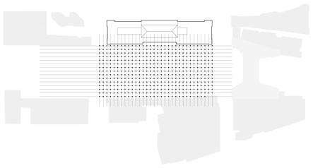
The structure of the hyperloop sta tion has been decisive for the project development and design. We started by analyzing the existent structure of the GO train and VIA Rail concourse located respectively at 1,00m and 1n50m above the street level of the south part of the rail corridor. The existent structure follows an 8x8 meters pillar grid and bears the weight of the platforms and rails placed above it. We introduced a 16x16m pillar grid that fits into the exist ing one in order to carry the weight of the hyperloop hall (+16,00 m). At the hall level, we have a mixture of the 16x16 grid that is used to hold up the slabs above and the 32x16m grid that we use for the roof. The canopy, composed of the repetition of a rhomboid module, is supported by a 32x16m pillars grid [fig. 210].
The project is located in an area protected by the Union Station Herit
At the hall level there is a mixture of the 16x16 grid that is used to hold up the slabs above and the 32x16m grid used to support the roof.
285 age Conservation District , delimited on the north by Wellington Street, on the south by Lakeshore Boulevard and Harbour Street, on the east by Yonge Street, and on the west by Lower Sim coe Street and Rees Street. From the project’s point of view, the most import ant building in this Conservation Dis trict is the Union Station, because the new hyperloop station sits above the tracks and is directly connected to the old station building. In order to directly connect the new hyperloop station to the old one and maintaining a visible distance between the two buildings, we decided to have an in-between-space that connects the new hyperloop hall to the south façade of the Union Station and provides access to the Great Hall through a set of escalators and ele vators. In this in-between-space, that has a height of five meters (in contrast to the thirty-meter hyperloop hall) we have placed the vertical connections to the main hall, to the first train platform and to the train concourse. In this way
The only intervention on the his torical building that we propose, is the partial removal of the wall that divides the Great Hall from the train platforms , in order to connect the two halls. Cur rently, there is a ramp that leads trav elers from the great hall down to the VIA Rail concourse, passing through two imposing decorated columns. We decided to connect the great hall with the new hyperloop hall with elevators, stairs and four escalators. The latters are placed on the sides of the columns and are the most visible connection between the two spaces. By doing so, we decided to resume the concept proposed in the “Union Station Study” prepared for the City of Toronto in July 1974 for the Metro Centre development [fig. 213]. In the proposal of the 70s, this connection was part of the pro posed pedestrian route that connected the Downtown area to the lakeshore.
Architectural Focus
LEVEL +46,00m 32x16m grid at roof level
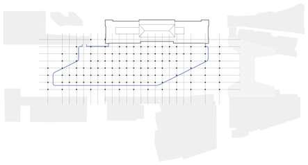
LEVEL +16,00m 16x16m and 32x16m grid at Hyperloop Hall level
we are able to fully connect the new building with the old one without dam aging the historical façade.
The canopy, composed of the repetition of a rhomboid module, is supported by a 32x16 meters pillars grid. The grid highlights the inclination of the hyperloop system tubes.

Design Project Report
The new station fits into the dense context by preferring a horizontal development to high-rise development, creating a background to Union Station without making it lose its importance.
Architectural Focus
Design Project Report 288
To save Union Station, Metro Centre integrated it to the project by introducing escalators that connected the elevated public plaza to the Great Hall.
Fig. 213: Metro Centre proposal of 1974 for the connection between Union Station Great Hall and the public plaza above the rail corridor.

289
The project shares similar features to the Metro Centre proposal.
Architectural Focus
Fig. 214: Project proposal for the connection between Union Station Great Hall and the Hyperloop Hall.

velopment project were, in our opinion, ahead of time.
From the Great Hall, people could have followed the ramp down to the rail concourse or could have taken the two escalators up to the Union Plaza, a proposed pedestrian public space above the rail platforms [fig. 216]. In the study there are different proposals for the project: either the rail corridor was maintained where it is today, or it was moved to the South. All proposals have the connection with the Great Hall [fig. 215], but the difference is that they con nected either a plaza or a retail space . We decided to use this concept because it worked perfectly with our project and because some of the ideas proposed in the 1970s with the Metro Centre de
Fig. 217: (on the right, below) Section of the pro posal of the Union Station Study in 1974 for the Metro Centre project.

Design Project Report 290
Fig. 216: (on the right, above) View of the Union Plaza and atrium above the rail corridor. Proposal of the Union Station Study in 1974 for the Metro Centre project.
Rethinking all the connections is an important topic of our project because of the complexity of the site: we created new connections and paths and inter vened on the existing ones in order to improve and integrate them. Also, we wanted to highlight the hyperloop sta
Fig. 218: (next page) Intermodal Hub and public space vertical connections.
Accesses and connections
Fig. 215: (above) Four ter minal concepts developed for the Union Station Study in 1974 for the Metro Centre project.
The project aims at optimizing the existing connections between the dif ferent infrastructures that are present in the site project and, at the same time, create new ones that we believe are ne cessary to make the hub work [fig. 218].
291 Architectural Focus


Design Project Report
the amount of space available and ac cording to the importance of their loca tion.The main entrances from the street level are located on the north side through the Union Station Great Hall and on the south part through the monumental staircase that connects the street level to the park level and there fore to the plaza in front of the southeast entrance of the hyperloop station. The south staircase, composed of steps and ramps, presents, on its sides, two
Fig. 219: (previous page) View of York Street north connection with the elevat ed deck.
Architectural Focus
tion as the central connecting point: it puts in communication the elevated park, the historical building of Union Station, the train platforms, the Sco tiabank Arena, and the Union Station Bus Terminal. Therefore, we provided a 360° access to the station building and, as described before, the elevated bridge is fully connected to the street level on both sides of the rail corridor with staircases, elevators, escalators, and ramps, some of them having more monumental than others according to
Fig. 220: (below) South elevation.
Design Project Report 298
of the project and the traveler feels less disoriented when looking for the station entrance.Thenorth entrance of the Hyperloop Hall is connected with the Great Hall through a set of escalators immediately visible from the entrance of the old building and placed in the centre of its symmetrical plan. The escalators dir ectly connect the two halls and are lo cated in a way that, when the visitor ar rives from the Great Hall, finds itself in the middle of the hyperloop hall, direct ly facing the check-in area. The new hall is reachable also with two symmetrical elevators and staircases located on the sides of the escalators a bit down the ramp that connects the Great Hall to the VIA Rail concourse. As mentioned in the chapter “Heritage” these connec tions lead to the in-between-space of five meters height that visibly separates the Great Hall from the Hyperloop one. This longitudinal space host also es calators, elevators and staircases that directly connect the hall (+16,00m) with the GO train and VIA Rail concourse (respectively +1,00m and +1,50m). This connection makes it possible also to have a faster way to reach the subway station and the streetcar stop that are located in the northeast part of the Union Station building at -8,70m from the street level.
The Hyperloop Hall is connected to other two existing buildings in addition to the train station. On the northwest part, it is connected to the UP Express building, which is part of the Union Cen tre Tower proposed development. It was fundamental for us to have a dir ect enclosed connection between the
tunnels that provide direct access to the GO train and VIA Rail concourse at +1,00m and +1,50m, and to a set of es calators and elevators that bring to the elevated park above. Here, a wide path way leads the visitor to the entrance of the Hyperloop station. The choice of introducing a monumental staircase in this portion, between two buildings and covering the current south entrance of Union Station, has been a result of our consideration about how to highlight better the south entrance. In fact, now adays the only monumental access to Union Station is provided by the station building on the north side, due to the fact that, during the years, the city has evolved mostly in the north part of the rail corridor, while the waterfront was used for industrial purposes. With the dismission of the rail yard in the 1960s, the south part of the corridor has wit nessed radical changes. Especially in the last twenty years, the waterfront area has been revitalized and densified by the presence of many skyscrapers. This led to the progressive hiding of the south entrance of the train station that, as a consequence of the densification of the waterfront portion, has become a busy entrance for people who live and work in the area. It is then obvious that the current south entrance doesn’t satisfy the needs of the newly redevel oped part of the city, and its scale, now defined by a small one-story-high en trance, contributes to hiding the pres ence of the station that is not visible due to the skyscrapers. With the monu mental staircase and the new station volume, the Intermodal Hub is more visible from the street level on all sides
Our vision for the functioning of the hyperloop station is a hybrid between an airport, a train station, and a subway station. We combined all the perks of the different infrastructures into our sta tion design. From the airport we chose the security aspect and, therefore, the separation of arrivals from departures, also on different floors of the station; from the train station we took the short distance from entering the station to getting on your train; from the subway, we selected the frequency of trains that departure from each platform.
299 two buildings because, also in this way, the traveler has a shorter way to reach another important means of transport of the Intermodal Hub. The last building that we decided to connect with our hall is the Scotiabank Arena which hosts part of the PATH system that leads to the Union Station Bus Terminal located in the CIBC Square south tower. Since our building does not confine with Sco tiabank Arena and it was important to have an in-door connection, we decided to create a tunnel, located two meters below the hall level, that could link the spaces and extend the PATH system. The tunnel is reachable by some steps and a ramp from the hall part and on the other side is connected to the PATH, the elevated park, and the street level. The tunnel, which has a height of four meters, is covered by a walkable green roof so that it doesn’t represent a barrier to the extension of the linear park. On the east side of this small hill, we placed six pairs of escalators and six elevators that connect the park (+16,00m) to the train platforms below (+5,90m).Another
entrance to the hall is pro vided by the staircase on the north side of York Street that, passing through a small garden, leads the visitor to the Hyperloop Hall. The west entrance faces the east entrance of the commer cial gallery (part of the PATH system expansion) and the bigger green hill.
Providing this many entrances and connections was necessary in order to develop a well-connected Intermodal Hub that can perfectly work all year long, despite the extreme temperatures that the city experiences during winter and summer.
When entering the hyperloop hall, the traveler finds himself in a big and
Fig. 221: (next page) Floor plan +16,00m.
Architectural Focus
Hyperloop Station functioning
The Hyperloop station presents three floors above the hall level that are connected through staircases, es calators, elevators and inclined mov ing walks, that typically only have one direction: either they go up or go down.
Along the south façade, there are placed all these vertical connections that con nect the check-in areas (+16,00m) to the last floor of the gates (+35,00m). The latter is connected to certain parts of the level below (+30,00m), occupied by the hyperloop platforms, with elevators and escalators only moving down. The platforms that are not connected to the gate level have elevators, staircases and escalators going down to the lower level (+23,00m). This level is connected with the hyperloop hall with vertical connections accessible by anyone. We also planned fire escape staircases that connect all the levels and private ac cesses for the station employees.
2223 27 26 24 25 2930 28 25 30.29.28.26.25.24.23.22.21.20.19.18.16.15.14.13.12.11.10.9.8.6.5.4.3.2.1.7.17.27.
CIBC
rental & repair
Check-inRetailDrugpointstoreand security controls
UndergroundJurassikParkPark parking
Fast
check-in and security controls AccessSecurityto the offices PathConnectionImmigrationTechnicalRestaurantLockersroomofficetogatessystemandconnection to bus station
Union Centre connection Convention
and
Coffee bar
Connection
to train platforms
SkateRestaurantRetailpark/ice
UnionPlaygroundPark
Hyperloop ConnectionHalltothe train concourse
Centre
Info
parking
to UP Express Metro
skating
Bike
Union Station Hall
Bike
21 54 13 14 15 10 10 6 7 1315 10 712 13 17 19 18 2021 33 8 8 9 11 11 16
3.2.1. OpenOffice Arrivalsspace
3 1 1 1 2 3 2 3 2
welcoming space [fig. 221] with green ery, seating areas and commercial activities such as a coffee bar, a drug store and retail shop. We also placed some facilities for the passengers and tourists such as an info point and a lug gage storage. From the hall, there is direct access to the security controls. We placed two big ones and a smaller one that is used as a fast track for those passengers with no luggage or with a priority ticket. We decided to have sec urity controls like those of the airports, instead of none as in the subway sta tion, for two main reasons: firstly, some destinations of the Pods are located in the U.S., where there are different laws and immigration controls, secondly, the concept of the Pod is similar to an airplane, where you don’t have a direct
Fig. 222: (previous page) Floor plan +23,00m.
escape to the outside and therefore the passengers must have passed strict security controls.
1 2 1 2 1 2 1 Design Project Report 304
Fig. 223: (above) Floor plan +30,00m.
Once passed the security controls, the traveler is directed towards the south façade where the vertical con nections (elevators, escalators, inclined moving walk and stairs) are located. These vertical connections bring people to the last floor of the hyperloop station, placed three floors above the hall, with no stop at the other levels.
2.1. ArrivalsDepartures
The last floor hosts the gates [fig. 224] that provide access to the hyper loop infrastructure itself. From here people can have a privileged view of the station below [fig. 226], especially of the hyperloop tubes, and on the city and the Lake Ontario. As a matter of fact, it was important for us to provide new points
themselves. On this level people are not supposed to wait for their Pod, on the contrary, it is a floor where people keep moving whether they just arrived, or they are leaving. The four arrival plat forms have stairs, escalators and ele vators that connect to the floor below.
of view of the city and create unique ones. On this floor, there are four gates that provide access, after the ticket con trols, to the departure platforms below. Key to the design of the different floors is the optimization of time: the station is not working as an airport, where queues and waiting times are long, but rather as a subway station where you only wait a little time on the platform (in our case at the gate level).
Architectural Focus
Fig. 226: (following pages) View of the Hyperloop Sta tion from the last floor.
The floor below the platforms is in tended for exits and for office uses [fig. 222]. The public and the private use of this floor are always separated. Trav elers that arrived and are exiting the station use the corridor of this floor to reach the hyperloop hall [fig. 225] where they will be guided in the four different directions: to the North towards the Union Station Hall and the Downtown, to the east and the west towards the elevated park and to the South to the Waterfront area.
4.3.2.1.
Fig. 227: (following pages) Longitudinal section.
1 1 1 1 2 3 4 305
Fig. 230: (following pages) View of the Hyperloop Station from the hill.
Fig. 224: Floor plan +35,00m.
Fig. 229: (following pages) View of the green corridor in front of the Hyperloop Station.
CoffeeGate bar
The platform level [fig. 223] con sists of seven platforms and six tubes, the latter with two Pods in each, with the possibility of hosting three Pods in a future expansion. The platforms are divided into three arrival platforms and four departure ones, alternated with each other, so that the flows of people in the two directions are never mixed
Fig. 225: (following pages) View of the Hyperloop Hall.
Fig. 228: (following pages) Axonometric section.
RetailBistrot


is facing the Lake Ontario and offers the city the view of the lake from a level that usually isn’t reachable. Another im portant aspect is that this hill provides a big green area, distant from the urban traffic, where citizens can lay down and enjoy the view of the skyscraper and the iconic CN Tower.
The central part of the park is called “The Hill” and hosted, before our inter vention, part of the PATH with two ele vated bridges. We decided to demolish them and re-propose the covered con nections integrated into our project. Through this covered space, which now is a gallery with retail, functions for the park and a bike rental and park ing, we established again the connec tion between the two buildings of the Metro Toronto Convention Centre, the UP Express building (updated with the proposed project by BIG – Bjarke Ingels Group), office buildings and a hotel. Converting the space from linear bridg es to surfaces with functions helped us give back to the city a space that can be used all year long. With the introduction of the commercial gallery, we would have lost the linear connection created by the park through the entire elevat ed platform. Therefore, we converted the roof of the gallery into a green walkable space, connected to the park through two slopes, one for each side, that don’t exceed the 6%. The ramp in the west is smaller and placed side by side with an expanse of flowers, while the east one is surrounded by greenery where people can easily find a comfort able place to sit due to its inclination. The ramps create two small squares that provide the access to the covered gallery. The top of the hill, located six meters above the park level, provides new observation points of the city: the one in the north is facing the downtown and provides a new perspective of the skyscrapers, while the one in the south
Fig. 232: (below) View of the entertainment area in winter with the ice skating rink.
The Entertainment
Fig. 231: (above) View of the entertainment area with the skateboard park.
The Hill
The first part of the elevated park is called “Entertainment” and is located in the so-called Entertainment District, next to the CN Tower, the Rogers Cen tre and Ripley’s Aquarium of Canada. The functions we located in the area are a basketball field and a playground accessible to anyone, seen the lack of open-air sports areas in the surround ings. This extension of the entertain ment district is a completion of the space around the CN Tower: now the iconic building of Toronto doesn’t look as isolated as before. The project con nects the buildings on the other side of the rails, creating an interconnected space by also solving the different ground levels.
Design Project Report 318
319 Architectural Focus


Building over an existing structure and between the rail tracks
321
green roof. This makes it necessary to use pillars in certain places as they satisfy the architectural and structural needs of the upper floors. Secondly, the structure present on the concourse floor dictated the choice of using a pil lar structure in that portion as making load-bearing continuous walls would have been too invasive and would have caused problems at the passenger circulation level in a space that must instead be spacious and permeable. These two reasons suggested the use of a grid of pillars but, due to the inter section of the train tracks in the west ern part of the project area, the latter would not have been able to fit into the current layout of the tracks while re specting the distances from them and without imposing major works to move some of the tracks. Thus, there was
TECHNICALSTRUCTURALANDSTRATEGY 5.4
Fig. 233: Sketches of the structural design process.
The train concourse is located at a lower level than the railway platforms and tracks. It has a supporting struc ture composed of a grid of 8x8m pillars, each with a diameter of 1 meter. They are positioned following a regular orth ogonal grid that goes to determine the specularity of the plan of this floor. For the construction of the bearing struc ture of the first deck, which hosts the park and hyperloop hall, we used a mixed structure – pillars and walls – for three main reasons. Firstly, the weight that the plate floor must support is not always uniform, as in the hyperloop sta tion portion there are three additional floors above it and in the commercial gallery portion, there is a walkable
a need to widen the span of the sup porting structure so that it did not inter fere with the joining tracks. In addition, the rail corridor narrows in the west ern part of the project area, favouring the use of a structure composed of load-bearing walls that run parallel to the tracks that do not intersect with others, a solution typically employed for the construction of a floor above a rail corridor, as it happened in the Manhat tan West development in New York City or in the Paris Rive Gauche project in the capital of France. Therefore, these three factors determined the use of a mixed pillar-wall structure according to the needs of the different portions of the
thick walls running parallel to the Metro Toronto Convention Centre build ings at a distance of 40 meters from each other. Between the two walls is a row of pillars (Ø 1,50 m) with a span of 16 meters, into which the pillars sup porting the hyperloop infrastructure are inserted every 32 meters. In some cases, the latter are incorporated into the supporting walls where individual pillars cannot be placed. The walls are placed at varying distances (min. 8m and max. 34m) depending on the ar rangement of train tracks. As the rail passes over Lower Simcoe Street, the walls have been interrupted, so that the road continues, and are connected to each other by a beam.
Design Project Report 322
Theproject.western part has two 80-cm-
Fig. 234: Plan highlighting the new structure (railway level).
Fig. 235: (on the right)
Exploded axonometry.structural
323 Technical and Structural Strategy
nel between the Hyperloop Hall and the PATH that crosses the Scotiabank Arena and leads to Union Station Bus Terminal, we needed to build a slab that was lower than the floor level of the hall (+16,00 m). To do this, we employed a 100-cm-thick Gerber beam [fig. 239], which allowed us to have a floor that was two meters lower (+14,00 m). The beam has wings of 50cm each, which support the precast and prestressed segmental beams of the slab.
When the Hyperloop Station section begins, the structure consists of a 16x16 grid of pillars (Ø 1.50 m) that then fits into the existing concourse floor grid. The reinforced concrete pillar has a
Covering the rail corridor
The pillar-wall mixed structure bears the weight of the elevated deck that is located at +16,00m from the street level on the south of the train sta tion and at +10,50m from the train rails. The deck is composed of a succession of parallel decks that in turn are formed by the connection of precast and pre stressed segmental beams [fig. 236]. One single element is 3,50m wide, 1,00m large and 2,50m high. In its lowest part of the sections, it hosts some holes for the prestressed cables that compress the deck. This solution was used in a similar way in the Manhattan West development [fig. 237] by SOM Architects (2015) for covering the rail metro lines and creating a large plaza above them. In order to build the connecting tun
Design Project Report 324
The Hyperloop Station structure
Fig. 236: The succession of parallel decks forms the elevated deck.
Fig. 237: (on the right, above) Construction site of Manhattan West deck. Pla cing of the parallel decks.
Fig. 238: (on the right, below) Construction site of Manhattan West deck. The parallel decks are placed one next to the other.
325 Technical and Structural Strategy


of four beams that create the “frame”. The beams of the rhomboid element lean on a shelf that hangs on the cross pillar [fig. 241] and are linked to tie rods connecting then to the top of the pillar. Here, the eight beams of the four rhom boid frames that meet at every pillar, rest on a steel profile that fixes them to the vertical structure but enables the movement of the beam caused by the thermal dilatation [fig. 243]. It is in fact, common in big structures like the one we are designing, is to have a dila tation joint. In our case, we choose this joint solution that enables the beams to shift back and forth when subjected to expansion or compression (phenomena that are more frequent with the ex treme weather conditions of Canada). The junctions of the beams with the shelf are protected from the outside en vironment through an aluminum cover.
Fig. 240: (below) The reinforced concrete pillar with circular section has a steel cross core with embedded rebars around it. It maintains its section until it arrives at the last floor before the roof. Here it presents a cross shape section that progressively reduces itself from the roof to the top of the pillar.
Design Project Report 326
Fig. 239: (above) The Ger ber beam was used for the realization of a -2m level slab for the PATH.
The pillars that follow the 32x16m grid present only the cross shape when they sustain the roof structure [fig. 240]. This design choice has been dictated by the will of showing the structure of the project and because the cross-shaped pillars were visibly suiting when they meet the roof structure. The pillars that hold up the roof are 35,80 meters high, and we introduced, on the outside of the station, bracing elements con necting pillars on the extremity and in the central part of the area occupied by the structure [fig. 242].
steel cross core with embedded steel rebars around it, that increase the per formance of the pillar from the point of view of tension and compression.
The roof is composed of a repeti tion of the same module that is given by the 32x16 grid and the inclination of the hyperloop tubes. The module is a rhombus with sloping sides composed
327 Technical and Structural Strategy
Fig. 242: (below, on the left) Bracing element.
Fig. 241: (above) Roof beams connection and aluminum cover. 15-cm-downspoutTheis visible.
Fig. 243: (below, on the right) Roof beam thermal dilatation (expansion and compression).
Design Project Report 328


The interior part of the rhomboid module hosts a hyperbolic panel whose structure is composed of a sequence of small triangular panels. This small triangular module that composes the rhomboid panel has been introduced in order to satisfy the structural needs of the hyperbolic shape. In fact, we stud ied similar projects that used triangu lar elements to create free shapes. Our main references are the Milan Trade Fair Rho Pero by Fuksas Architects in 2005 [fig. 244], the Department of Islamic Arts at the Louvre Museum in
Fig. 244: (top left) Fuksas Architects, Trade Fair Rho Pero, Milan, 2005.
Fig. 245: (bottom left) Mario Bellini and Rudy Ricciotti, Department of Islamic Arts at the Louvre Museum, Paris, 2012.
329 Technical and Structural Strategy
Paris by the architects Mario Bellini and Rudy Ricciotti in 2012 [fig. 245], and the Moynihan Train Hall at Penn Station in New York City by SOM Architects in 2021 [fig. 246]. In addition, we decided to characterize the rhomboid panels with three different solutions that are used in different parts of the roof according to what they cover [fig. 247]. The first one is a glazed surface with solar cells The solar panels are partially covering the glass and have a high level of trans parency in order to prevent them from reducing the amount of light entering
Fig. 246: (top right) SOM Architects, Moynihan Train Hall at Penn Station, New York City, 2021.

Fig. 249: (on the right) Pelli Clark & Partners, Piazza Gae Aulenti, Milan, 2013.
Design Project Report 330

Fig. 247: (above) Three typologies of the roof pan els (glass, glass with solar panels and wood).
Fig. 248: (below) Ben them Crouwel Architects, Rotterdam Central Statio, Rotterdam, 2014.
331 Technical and Structural Strategy

the station or creating too much shade outside. For these solar panel cells in corporated in the glazed roof panel, we took as a reference the roof of Rotter dam Central Station [fig. 248] by Ben them Crouwel Architects (2014) and the shelters of Piazza Gae Aulenti [fig. 249] in Milan by Pelli Clark & Partners (2013). We used then glass panels for the areas that needed more sunlight, such as the parts above the hyperloop platforms. In this way, we contributed to highlighting the presence of the tubes and their peculiar inclination from the top view that, here in Toronto becomes the fifth façade due to skyscrapers, es pecially in this area because of the priv ileged sight from the CN Tower at 447 meters. The third type of panel that we used for the roof is a wooden panel that follows the perimeter of the Hyperloop Station and makes it easier to create a connection between the glazed façade and the hyperbolic roof.
a downspout (Ø 15cm) inside them. On the four sides of the cross pillars, there is an opening per each that enables the entrance of the water, that has been col lected in that portion of the roof due to the inclination of the rhomboid element, in the pipe.
Design Project Report 332
As mentioned before, we used a solu tion of precast and prestressed seg mental beams whose succession forms the slab for the park and walkable hill decks, while for the station upper floors we used the bubble deck solution. It is a technology that eliminates a significant percentage of concrete from the slab by having plastic balls incorporated. This creates a flat slab that spans in two dir ections. We used this solution to avoid heavy beams and to have a higher de gree of freedom in shaping the perim eter of the different slabs.
To solve the problem of rainwater collection and disposal, we designed the cross pillars that reach the roof with
The connection between the exter ior envelope and the building’s roof [fig. 250] is made by an opaque element, 20cm thick, shaped to follow the course of the roof since the latter is not flat. It fits into the glazing mullions at a height of +26,50 meters from the hall floor level (+16,00m) and has vertical grooves that recall, and double, the repetition of the mullions. The connection between the glass, the mullions and the opaque ele ment is made by a closing beam placed horizontally at the end of the facade (+27,50 meters) and provides protection to the elements.
Fig. 250: Connection be tween the glass façade and the opaque element.
333 Technical and Structural Strategy
Toronto has proven to be a perfect cradle for the development of this re search by design, not only because of its significant global economic growth but also because of the opportunities and needs for intervention that the Union Station area offers. We chose the latter for its significant levels of infra structural interchange in the city and the region, making the benefits of a sys tem like hyperloop more efficient. Consequently, the thesis outcome involves the development of the project of a hyperloop hub adjacent to the ex isting Union station, which extends to the regeneration of the parts adjacent to the intervention site.
CONCLUSIONS
This thesis objective is to identify the ways through which a city such as Toronto could accommodate a new transportation system that aims for “ul tra-high speed” global connections and take advantage of it to revitalize the public realm of the area of interest.
334
Given the scale of development, the design work involved spatial, urban, and architectural scales. The proposed connections and geography of the area identify Toronto as a desirable inter change node between some of North America’s most important cities, such as New York, Chicago, Detroit, and Montréal, going a long way toward en hancing the possibilities for growth.
The project shows how the intro duction of a new infrastructure system into an already defined context, such as the Union Station District, can trigger urban regeneration processes to in crease the quality of public space avail able to the city.
The result and methodologies are also aimed at subsequently finding pos sible applications in other places of the world, however, bearing in mind that each context has its specificities and needs.
The possibility of improving the pub lic realm of the context is motivated by case studies of intervention on inter modal hubs designed to improve the city’s transportation efficiency and con nections, which have led to the boom ing urban regeneration of the area in which they are located. Therefore, the implementation of a new transportation system is not only aimed at the infra structural improvement of the city and its global relations but can also be seen as a pretext for initiating revitalization processes.Withthe aim of giving a base to the development of the new station, we decided to build an elevated plate covering the tracks, which allowed us to create a new level of public space available to the city in a dense area where it is difficult to find large empty spaces. The addition of the plate com pletes, between the CIBC Square bridge and Union Park, the new urban level that is gradually forming in a punctual manner at an elevation above the rail road tracks. In fact, the area is divid ed by the rail corridor, which worsens the connections between Downtown and the waterfront. The configuration of the deck, whose complex structural composition is based on technologies applied in cases such as “Manhattan West”, thus aims to exploit the space of the rail infrastructure as a new element of connection. In addition, the design defines a continuity between the spaces on that level by helping to provide new views of the city and relationships with
adjacent buildings.
The hyperloop hub project seeks a dialogue with the heritage building of the Union station and wants to estab lish itself as the central point of a sys tem that is currently disconnected in all its parts. In fact, its location allows it to link all the infrastructure systems in the area (railway, bus lines, UP express, subway, streetcar, ferries, and sports facilities), improving their connections and thus defining Union Station as a complex Intermodal Hub and landmark for the city. Hence, we decided to char acterize the architecture of the building through a strongly horizontal layout that contrasts, together with the sys tem of large public and green spaces, with the context in which it fits, which is composed of a high percentage of sky scrapers.Thenew building has been designed considering the current and possible future needs of travelers, citizens, and visitors, defining a dynamic station adaptable to future changes.
335
336
MENTSAKNOWLEDGE-
Lastly, we would like to thank our friend Giacomo D’Andrea, who we met in Toronto and showed us around the city.
337
A generous contribution has been made also by Prof. Arch. Brigitte Shim, who made herself available for online and in-person meetings and introduced us to the public aspect of the project site, through the Waterfront Toronto Association. Architect Leon L. H. Lai provided us with useful information about the future developments and in tentions for the area.
The thesis process has been form ative and we were passionate about it, allowing us to develop themes that characterized our study paths. This has been possible mainly thanks to our supervisors, Prof. Arch. Carlo Alberto Maggiore (PoliMi) and Prof. Arch. Eng. Roger Riewe (TU Graz), who followed the thesis with perseverance and inter est. We would also like to thank both Eng. Egone Costa and Eng. Alessandro Aronica for the support they gave us throughout the design phase. With their valuable advice and suggestions, we have deepened the structural concept making the development of the thesis complete.Animportant mention has to be made to Prof. Paolo Scrivano who, through his Torontonian experience as a Professor at the University of To ronto, introduced us to the historical background of the city while helping us to set the basis for the thesis develop ment.We would like to thank our universi ties, Politecnico di Milano and TU Graz, that made the Thesis Research Abroad program possible. Fundamental for the abroad stay was the Metropolitan University of Toronto (former Ryerson University) which welcomed us as visit ing researchers. Prof. June Komisar followed our application and, when we were in Toronto, shared her knowledge about the city and the intervention area several times.
We are deeply honored to have col laborated with TransPod Inc. on the de velopment of the architectural concept for the hyperloop system. We also had the possibility of arranging interviews with Arch. Graeme Stewart from ERA Architects, who explained to us their intervention in the Union Station Re vitalization project and provided us with valuable materials.
338
SOURCES
BlogTO, January 23, 2014. [Online] Available at: Behrens,unbuilt_mega_projects_in_toronto/.https://www.blogto.com/city/2014/01/the_top_5_Christiaan,andPels,Eric.“IntermodalcompetitionintheLondon–Parispassengermarket:High-SpeedRailandairtransport”.J ournal of Urban Eco nomics, Amsterdam, The Netherlands. 2012
Bélanger, Pierre. “Underground Landscape: The Urbanism and Infrastructure of Toronto’s Downtown Pedestrian Network.” Tunnelling and Underground Spa ce Technology 22, no. 3 (May 1, 2007): 272–92. [Online] Available at: https:// Bellerive,doi.org/10.1016/j.tust.2006.07.005.David.“UACTurboTrain”, Rail Fans Canada. [Online] Available at: https:// Bertolini,www.railfans.ca/via-rail-canada/engines/uac-turbotrain.Luca.“Spatialdevelopmentpatternsandpublictransport: the applica tions of an analytical model in the Netherlands”. Planning Practise and Rese arch, 14(2), pp.199-210, 1999.
Biennale di Architettura 2018. Freespace Catalogue. Venezia: La Biennale di Vene zia. 2018.
BIG. “Formgiving, An Architectural Future History”. Cologne, Germany: Taschen, Blow,2020.Christopher. “Transport Terminals and Modal Interchanges: Planning and Design”, London, UK: Routledge, 2017.
Bozikovic, Alex. “Inside CIBC’s New Headquarters in Toronto, Which Aims to Be a Different Kind of Workspace.” The Globe and Mail, March 18, 2022. [Online]
339
Aboelsaud, Yasmin. “Canada Officially Investing in Hyperloop Transportation Con cept”, March 29, 2019. [Online] Available at: Bateman,ARUP.ARUP.ARUP.AICAP.transpod-hyperloop-toronto-montreal-transport-canada-tender-2019https://dailyhive.com/vancouver/“Premiaicap2016Realizzazionidiopereincalcestruzzo”,2016.“RethinkingUrbanMobility.Threequestionsthatwillshapethefutureoftransportincities”,2019.[Pdf]Availableat:https://foresight.arup.com/publications/rethinking-urban-mobility/“Tomorrow’sLivingStation”,2019.[Pdf]Availableat:https://www.arup.com/-/media/arup/files/publications/t/tomorrows-living-station-comp.pdf“FutureofRail2050”,2019.[Pdf]Availableat:https://www.arup.com/-/media/arup/files/publications/f/arup_futureofrail2050_2019.pdfChris.“TheTop5UnbuiltMegaProjectsinToronto.”
Available at: Davies,Conceição,CommunityColledge,CNBC.Clayton,Chen,CIBCBureau,Brugh,Brownrent/article-inside-cibcs-new-headquarters-in-toronto-which-aims-to-be-a-diffehttps://www.theglobeandmail.com/arts/art-and-architecture/Christopher.“StillStanding:ACenturyofUrbanTrainStationDesign”.IndianaUniversityPress,Bloomington,IN,USA,2005.O.,Sharp,E.“Amtrakstationprogramandplanningguidelines”,2013.[Pdf]Availableat:http://nrvrc.org/nrvpassengerrailstudy/resources/research/national/Amtrak_Station_Program_Planning_Gui-delines.pdfUSCensus.“Census.Gov.”Census.gov.AccessedApril21,2022.https://www.census.gov/en.htmlSQUARE.“CIBCSquare”.[Online]Availableat:https://www.cibcsquare.com/Chia-lin;Hickman,Robin,andSaxena,Sharad,“Improvinginterchanges:TowardbettermultimodalrailwayhubsinthePeople’sRepublicofChina”,AsianDevelopmentBank,MandaluyongCity,Philippines:AsianDevelopmentBank,2014.Frank,andShi,HongYun.“WOW!TorontoWastheSecondFastestGrowingMetropolitanAreaandtheTopGrowingCityinAlloftheUnitedStatesandCanada”,TorontoMetropolitanUniversity(May31,2019).[Online]Availableat:https://www.torontomu.ca/centre-urban-research-land-development/blog/blogentry35/.WhyTheUSHasNoHigh-SpeedRail,YouTubevideo,2019.[Online]Availableat:https://www.youtube.com/watch?v=Qaf6baEu0_w.Mike.“ShouldCanadaExpandTrainTravel?”,Paris,France:Ipsos,2017.[Pdf]Availableat:https://www.ipsos.com/sites/default/files/ct/publication/documents/2018-02/expanding-train-travel-canada.pdfDevelopmentConsultantsLimited.“MetroCentreDevelopingandProgramme:AStudyontheDevelopmentofCanadianNationalandCanadianPacificRailwayLandsinCentralToronto”.Toronto:CommunitydevelopmentConsultantsLimited,1968.AnaLuísaMartins.“Fromcity’sstationtostationcity,anintegrativespatialapproachtothe(re)developmentofstationareas”.Delft,TheNetherlands:DelftUniversityofTechnology,2015.Alex,andGiang,Vivian.“11WildHighwaysToDriveBeforeYouDie.” Busi ness Insider, August 29, 2012. [Online] Available at: https://www.businessinsi der.com/the-worlds-11-wildest-highways-2012-8.
Sources 340
Filey, Mike, and John Taylor. The Open Gate: Toronto Union Station. 1st ed. Toronto, ON: Peter Martin Associates, 1972.
Koolhaas, Rem, and Bruce Mau. “S,M,L,XL”. New York City, NY, USA: The Monacelli Press, Inc., 1995.
Dezeen. “WilkinsonEyre Wraps Toronto Skyscraper in ‘Three-Dimensio nal Diamonds,’” June 9, 2022. [Online] Available at: Didelon,com/2022/06/09/wilkinsoneyre-cibc-square-skyscraper-toronto/.https://www.dezeen.Valéry.“Euralille:TheDeconstructionoftheEuropeanCity”. Log 39, pp. 119-135, 2017.
Ultra-High-Speed Tube Transportation: Dynamics of Vehicles and Infrastructure.” Procedia Engineering, X International Conferen ce on Structural Dynamics, EURODYN 2017, 199 (January 1, 2017): 8–17. [Onli ne] Available at: https://doi.org/10.1016/j.proeng.2017.09.142.
Flack, Derek. “10 Projects Toronto never built that would have transformed the city forever”, BlogTO, October 31, 2020. [Online] Available at: blogto.com/city/2010/11/the_top_10_unbuilt_projects_in_toronto/https://www.
European Commission “G7”, [Online] Available at: nisations/g7_en.od-farming-fisheries/farming/international-cooperation/international-orgahttps://ec.europa.eu/info/fo
ERA Architects. “Appendix 4 - Heritage conservation district plan”, Union Station District Plan, Toronto, ON, 2006.
Governmentde/de/projekte/463/hauptbahnhof-berlinofCanada,StatisticsCanada.“Census of Population,” January 15, 2021. [Online] Available at: https://www12.statcan.gc.ca/census-recense
Mazzeo, Giuseppe. “Impact of the High Speed Train on the European Cities Hie rarchy”. TeMA - Journal of Land Use, Mobility and Environment 1 (1), 2008.
GMP Architekten. “Berlin Hauptbahnhof”, [Online] Available at: https://www.gmp.
ERA Architects. “Heritage Impact Assessment: 141 Bay Street”, Toronto, ON, Ca nada, 2018.
341
Edwards, Brian. “The modern station: new approaches to modern architecture”. Abingdon, UK: Taylor & Francis, 1997.
ERA Architects. “Flyover Toronto, Heritage Impact Assessment”, Toronto, ON, Ca nada, February 5, 2020.
Janzen,ment/index-eng.cfm.Ryan.“TransPod
Peat, Marwick. “Union Station Study”. City of Toronto, 1974. Posluns, Jordyn. “Toronto Ranked #1 For ‘Population Growth’ In North America”, Narcity Toronto, June 3, 2019. [Online] Available at: Schivelbusch,th-americatoronto/torontos-population-is-growing-faster-than-anywhere-else-in-norhttps://www.narcity.com/Wolfgang.“TheRailwayJourney,TheIndustrializationofTimeandSpaceintheNineteenthCentury”.Berkeley,CA,USA:UniversityofCalifornia
Musk, Elon. “Hyperloop Alpha”, 2013. [Pdf] Available at: Parlotto,Osbaldeston,OMA.OMA.NORRsites/default/files/blog_images/hyperloop-alpha.pdfhttps://www.tesla.com/Architects.“UnionStationRevitalizationProject”,Toronto,ON,2018.[Online]Availableat:https://norr.com/project/union-station/“Euralille”,[Online]Availableat:https://www.oma.com/projects/euralille“UnionStation”,[Online]Availableat:https://www.oma.com/projects/union-stationOsbaldeston,Mark.“UnbuiltToronto,AHistoryofthecitythatmighthavebeen”,Toronto,ON,Canada:DundurnPress,2008.Mark.“UnbuiltToronto2,Moreofthecitythatmighthavebeen”,Toronto,ON,Canada:DundurnPress,2011.Federico.“TotalConnection”.
Sources 342
Metrolinx. “Union Station 2031, demands and opportunities study”, Toronto, ON, Canada: Halcrow Consulting Inc, 2012. [Pdf] Available at: Moore,Moneo,Moneo,Miorelli,tion_2031_Study_EN.pdftrolinx.com/en/regionalplanning/projectevaluation/studies/Union_Stahttps://www.meSarah.“ReconnectingthePATH:TorontoPATHWayfindingSystem.”Text,October20,2020.[Online]Availableat:https://segd.org/reconnecting-path-toronto-path-wayfinding-system.Rafael.“AtochaStationEnlargement”,[Online]Availableat:https://rafaelmoneo.com/en/projects/atocha-station-enlargement/Rafael.“Remarkson21works”.NewYorkCity,NY,USA:TheMonacelliPress,Inc.,2010.Derek.“WelcometoNewYork”.
McHugh, Patricia, and Alex Bozikovic. “Toronto Architecture, a City Guide”. Toronto, ON: McClelland & Stewart, 2017.
[Online] Available at: https://doi.org/10.6092/1970-9870/13.
Domus Air 1, December 2020.
Domus Air 2, July-August 2021.
Scrivano, Paolo. “Metro Centre: the “very obvious job” that was never built”. unpu blished paper, 2020.
“Cities and Stations”, Arup, 2022. [Online] Available at: https:// Tomer,Thorne,TheTaylor,Transpod.Transpod.Transpod.SpiekermannS.O.M.www.arup.com/perspectives/cities-and-stations.“MoynihanTrainHall”,[Online]Availableat:https://www.som.com/projects/moynihan-train-hall/&Wegener.“UrbanandRegionalResearch.Dortmund,Germany”.[Online]Availableat:http://www.spiekermann-wegener.com/index_e.htmlToronto,CA.[Online]Availableat:https://www.transpod.com/“ExpressFreightMarketreport”,Toronto,ON,Canada:TranspodInc.,2018.“TranspodinAlberta,summaryofstudyontheimplementationofaTransPodlinefromCalgarytoEdmonton”,Toronto,ON,Canada:TranspodInc.,June2021.Catherine,Hyde,DavidJ.,andBarr,LawrenceC.“HyperloopCommercialFeasibilityAnalysis:HighLevelOverview”.Cleveland,OH,USA:NASA,GlennResearchCenter,2016.Star.“LengthofBeijing-HKRailNetworkSameasEquator.”,[Online]Availableat:https://www.thestar.com.my/aseanplus/aseanplus-news/2022/01/01/length-of-beijing-hk-rail-network-same-as-equator.Martha.“ModernTrainsandSplendidStations:Architecture,Design,andRailTravelfortheTwenty-firstCentury”,London,UK:MerrellPublisher,2001.Adie.“MoreLessonstoLearn:ContinuedKnowledgeGapsinAmericanHigh-SpeedRail”,
Toronto, City of. “PATH – Toronto’s Downtown Pedestrian Walkway.” City of Toron
Smith,nes-index/Malcom.
343 Press Books, 2014.
ASPA , Public administration review, Whiley, Hoboken NJ,
USA, Vol. 72, No. 3, May-June 2012
Sewell, Cathy. “RLB crane index”, Rider, Levett, Bucknall, 2022. [Pdf] Available Smith,2022-Crane-Index.pdfhttps://s31756.pcdn.co/americas/wp-content/uploads/sites/4/2022/03/Q1-at:Ainsley,“TorontoDominatesNorthAmericaforMostCranes”, Storeys. (April 9, 2021). [Online] Available at: https://storeys.com/toronto-q1-2021-cra
Available at: https://urbanto
Domus Air 2, July-August 2021.
UNStudio. “Hardt Hyperloop”. [Online] Available at: https://www.unstudio.com/en/ Urbanpage/11735/hardt-hyperloopToronto.“UnionCentre”,UrbanToronto. [Online] Available at: https://urban Urbantoronto.ca/database/projects/union-centreToronto.“UnionPark”,UrbanToronto.[Online]
to. City of Toronto, August 15, 2017. Toronto, Ontario, Canada. [Online] Avai lable at: UNStudio.Uffelen,Trip,TorontoToronto,Toronto,tos-downtown-pedestrian-walkway/.https://www.toronto.ca/explore-enjoy/visitor-services/path-toronCityof.“RequestforproposaltoRestore,DevelopandOperateTorontoUnionStation”,2001.TorontoReferenceLibrary,Tororntopubliclibrary,Toronto,ON,Canada.Cityof.“Downtownmobilitystrategy”,April2018.[Pdf]Availableat:https://www.toronto.ca/wp-content/uploads/2018/04/9700-downtown-mobility-strategy-city-panning.pdfRailwayHistoricalAssociation.“TorontoUnionStation”.[Online]Availableat:https://www.trha.ca/trha/history/stations/toronto-union-station/.JanJacob.“Whatmakesacity?Planningfor‘qualityofplace’:Thecaseofhigh-speedtrainstationareadevelopment”.Amsterdam,TheNetherlands,:IOSPress,2007.Chris.“Stations”,Salenstein,Switzerland:BraunPublishing,2010.“Europeshortensdistances”.
Sources 344
Available at: https://www.wa Waterfrontterfrontoronto.ca/Toronto.“Waterfront
Design Review Panel”, 2022. [Pdf] Available at: White,Waterfrontbook--july-2021--final-public.pdftps://www.waterfrontoronto.ca/sites/default/files/documents/wt-drp-handhtToronto.“RollingFive-YearStrategicPlan2021/22–2025/26”,2020.[Pdf]Availableat:https://www.waterfrontoronto.ca/sites/default/files/connect/waterfront/43c8b245-d3cc-4b45-aac4-5ae0a98ab585/rolling-five-year-strategic-plan-2021-2022---2025-26-.pdfRichard.“PlanningToronto:ThePlanners,ThePlans,TheirLegacies,1940-80.”,Vancouver,BC:UBCPress,2016
Waterfrontronto.ca/database/projects/union-park-0Toronto.Toronto,ON,Canada.[Online]
White, Richard. “Urban infrastructure and urban growth in the Toronto Region, 1950s to the 1990s”, Toronto, ON, Canada: Neptis Foundation, 2003.
345
LIST OF FIGURES
346
4. Bipartition, common architectural composition of railway stations of the XIX and XX century. Drawing by Authors.
3. Toronto Union Station in 1907. 1907, Fonds 1244, Item 99, City of Toronto Archives, Toronto, Ontario.
7. Time-Space Map of Europe. From Spiekermann & Wegener, “Time-Space Maps”. Available at: https://www.spiekermann-wegener.de/mod/time/time_e.htm
5. Aerial view of Amsterdam Central Station in the 1930s. Photo by Fototechnische Dienst Lu chtvaartafdeeling, “Luchtfoto van Amsterdam”, from Nederlands Instituut voor Militaire Histor ie, “Amsterdam Centraal”, accessed June 12, 2022. Available at: search_s_mediatype:%22Foto%27s%22-71099ef7093a?mode=detail&view=horizontal&q=2011%200058&rows=1&page=1&fq%5B%5D=sie.nl/foto-s/detail/b7a362a6-b568-75a4-ec1c-12f265e8fea9/media/5d6c0494-7e8c-b499-00fahttps://nimh-beeldbank.defen
2. Timeline of the evolution of transportation systems. Scheme by Authors.
11. Sketches by Elon Musk for the Hyperloop system. Drawing by SpaceX, from Elon Musk, “Hyperloop Alpha”, 2013. Available at: https://www.tesla.com/sites/default/files/blog_images/ hyperloop-alpha.pdf
15. Proposal for the Toronto-Ottawa-Montréal corridor by Hyperloop One. Infographic by Vir gin Hyperloop. in C. B. C. News ·, “Toronto to Montreal in 39 Minutes? Futuristic People Mover Zips to next Stage | CBC News,” CBC, September 15, 2017. Available at: news/canada/ottawa/hyperloop-toronto-ottawa-montreal-route-winner-1.4291893.https://www.cbc.ca/
13. First complete test track in the Virgin Hyperloop test area in the Nevada Desert, From Vir gin Hyperloop, accessed April 12, 2022. Available at: https://virginhyperloop.com/
1. Aerial view of St. Pancras station and Kings Cross in London with the Kings Cross’ urban revitalization. In Will Bedingfield, “King’s Cross Has Become London’s Biggest, Buzziest Tech Hub,” Wired UK , May 7, 2019. Available at: https://www.wired.co.uk/article/st-kings-cross-techhub
347 CHAPTER 1
8. London - Paris - Brussels corridor with Lille as a central connective Hub for the cities. Draw ing by authors. Elaborated from OpenStretMap. Available at: https://www.openstreetmap.org/
6. High-speed train. Photo by Shutterstock, in Richard Holden, “Vital Signs: Sydney to New castle fast rail makes sense. Making trains locally does not “, The conversation, January 6, 2022. Available at: sense-making-trains-locally-does-not-174341https://theconversation.com/vital-signs-sydney-to-newcastle-fast-rail-makes-
10. Sketch of the Euralille project by OMA showing the different lelels of interchange of the hub. Drawing by OMA, from OMA, “Euralille”, accessed April 12, 2022. Available at: https://www.oma. com/projects/euralille
12. Timeline of the evolution of the concept of vacuum transportation technology. Scheme by Authors.
14. Comparison of carbon emission per transport mode between traditional transport sys tems and hyperloop (based on Hardt Technology). Infographic by Hardt Hyperloop, from Hardt Hyperloop, “Hyperloop network”, accessed April 12, 2022. Available at: https://hardt.global/ hyperloop-network
9. Aerial view of Euralille. Photo by Frans Parthesius, from OMA, “Euralille”, accessed April 12, 2022. Available at: https://www.oma.com/projects/euralille
22. Map of the High-Speed Rail network in Spain. Drawing by authors. Elaborated from Open StretMap. Available at: https://www.openstreetmap.org/
28. Detail of the rotunda façade. Photo by Michael Moran, from Rafael Moneo, “Atocha station enlargement”. Accessed May 10, 2022, Available at: https://rafaelmoneo.com/en/projects/ato cha-station-enlargement/
CHAPTER
Sources 348
24. Atocha station Masterplan. Drawing by Rafael Moneo Architects, in Rafael Moneo, “Re marks on 21 works”, (The Monacelli Press Inc., 2010).
16. The hyperloop syestem developed by TransPod company. Drawing by Authors (based on Transpod Technology). 2
29. Commuter train station hall. Photo by Michael Moran, from Rafael Moneo, “Atocha station enlargement”. Accessed May 10, 2022, Available at: https://rafaelmoneo.com/en/projects/ato cha-station-enlargement/
18. The components of an Interchange Hub. Infographic elaborated from Chia-lin Chen, Rob in Hickman et Sharad Saxena S, “Improving Interchanges: Toward Better Multimodal Railway Hubs in the People’s Republic of China”, (Asian Development Bank, 2014), p.8
17. The node-place model diagram. Infographic by Luca Bertolini, “The node-place model”, from Luca Bertolini, “Spatial Development Patterns and Public Transport: The Application of an Analytical Model in the Netherlands”, Planning Practise and Research, 14 , 1999, p.202.
19. Station layouts based on the organization of the tracks. Drawing by Authors.
25. Atocha station Cross section. Drawing by Rafael Moneo Architects, in Rafael Moneo, “Re marks on 21 works”, (The Monacelli Press Inc., 2010).
26. Atocha station Axonometry. Drawing by Rafael Moneo Architects, in Rafael Moneo, “Re marks on 21 works”, (The Monacelli Press Inc., 2010).
20. Aerial view of the Terminal station of Milano Centrale. Photo by World_walkerz, in, “La stazione centrale per Milano”, Assi & Partners, accessed April 26, 2022. Available at: https:// www.assipartners.com/news/stazione-centrale-per-milano/
30. Interiors of the rotunda entrance building. Photo by Michael Moran, from Rafael Moneo, “Atocha station enlargement”. Accessed May 10, 2022, Available at: https://rafaelmoneo.com/ en/projects/atocha-station-enlargement/
23. Atocha Station devolpment from Plaza del Emperador Carlos V.
21. Satellite image of the Atocha Station area in Madrid. Google Earth Pro 7.3.4. (May 22, 2022). Madrid, Spain. 40°24’26.48”N, 3°41’30.00”O, Eye alt 2,50 km. Accessed June 10, 2022. Available at: http://www.google.com/earth/index.html
31. Tropical winter garden in the former train station hall. From Fine Art America, Accessed May 10, 2022, Available at: w-chris-fooshee.html?product=posterhttps://fineartamerica.com/featured/madrid-atocha-train-station-
27. Brick-and-glass rotunda entrance building addition. Photo by Michael Moran, from Rafael Moneo, “Atocha station enlargement”. Accessed May 10, 2022, Available at: https://rafaelmoneo. com/en/projects/atocha-station-enlargement/
33. Map of the High-Speed Rail network in Germany. Drawing by authors. Elaborated from OpenStretMap. Available at: https://www.openstreetmap.org/
40. Organization and use of the different levels of the hub. Photo by Marcus Bredt, from GMP Architekten, “Berlin Central Station”, Accessed May 10, 2022, Available at: https://www.gmp. de/en/projects/463/berlin-central-station.
41. Main hub hall with the east-west rail corridor. Photo by Marcus Bredt, from GMP Architek ten, “Berlin Central Station”, Accessed May 10, 2022, Available at: https://www.gmp.de/en/pro jects/463/berlin-central-station.
39. Berlin Hauptbahnhof aerial view. Photo by Marcus Bredt, from GMP Architekten, “Berlin Central Station”, Accessed May 10, 2022, Available at: https://www.gmp.de/en/projects/463/ berlin-central-station.
43. Map of the Acela Rail corridor, part of the Amtrak network, connecting Washington DC to Boston. Drawing by authors. Elaborated from OpenStretMap. Available at: https://www.open streetmap.org/
37. Berlin Hauptbahnhof Perspective cross section. Drawing by Tonia Ludwig, Hannah Melzer, Aida Navidbakhsh, for Architectural design studio by Prof. Maurizio Meriggi, Prof. Tan Zhu, Prof. Vitomir Racic, Politecnico di Milano, A.Y. 2019/2020.
38. Berlin Hauptbahnhof view from Ludwig-Erhard-Ufer. Photo by Marcus Bredt, from GMP Architekten, “Berlin Central Station”, Accessed May 10, 2022, Available at: https://www.gmp. de/en/projects/463/berlin-central-station.
42. Satellite image of the Penn station area in New York City. Google Earth Pro 7.3.4. (May 22, 2022). New York City, NY, USA. 40°45’3.80”N, 73°59’43.48”O, Eye alt 2,50 km. Accessed June 10, 2022. Available at: http://www.google.com/earth/index.html
34. Berlin hauptbahnhof development. Photo by Marcus Bredt, from GMP Architekten, “Berlin Central Station”, Accessed May 10, 2022, Available at: https://www.gmp.de/en/projects/463/ berlin-central-station.
349
36. Berlin Hauptbahnhof Axonometry showing the organization of the tracks on the east-west and north-south directions. Drawing by Tonia Ludwig, Hannah Melzer, Aida Navidbakhsh, for Architectural design studio by Prof. Maurizio Meriggi, Prof. Tan Zhu, Prof. Vitomir Racic, Politec nico di Milano, A.Y. 2019/2020.
32. Satellite image of the Berlin Hauptbahnhof area. Google Earth Pro 7.3.4. (May 22, 2022). Berlin, Germany. 52°31’29.35”N, 13°22’11.00”E, Eye alt 2,50 km. Accessed June 10, 2022. Avail able at: http://www.google.com/earth/index.html
46. Cross section of the new Moynihan Hall. Drawing by S.O.M., from Archdaily, “Moynihan Train Hall / SOM”, Accessed May 10, 2022, Available at: https://www.archdaily.com/954941/ moynihan-train-hall-som.
45. Penn station development masterplan. Drawing by S.O.M., from Archdaily, “Moynihan Train Hall / SOM”, Accessed May 10, 2022, Available at: https://www.archdaily.com/954941/ moynihan-train-hall-som.
44. Aerial view of Madison Square Garden and new Moynihan Hall. Photo by Lucas Blair Simp son, from Archdaily, “Moynihan Train Hall / SOM”, Accessed May 10, 2022, Available at: https:// www.archdaily.com/954941/moynihan-train-hall-som.
35. Berlin Hauptbahnhof Masterplan. Drawing by GMP Architekten, from GMP Architekten, “Berlin Central Station”, Accessed May 10, 2022, Available at: https://www.gmp.de/en/pro jects/463/berlin-central-station.
48. Aerial view of the S.O.M. revitalization. Photo by Lucas Blair Simpson, from Archdaily, “Moynihan Train Hall / SOM”, Accessed May 10, 2022, Available at: https://www.archdaily. com/954941/moynihan-train-hall-som.
Sources 350
58. Toronto Skyline from Toronto Islands. Photo by Lisa Sabiucciu.
59. Canadian Railway system managed by Canadian Pacific and Canadian National. Drawing by Authors.
50. Detail of the entrance ceiling called “The Hive ” by Elmgreen & Dragset. Photo by An drew Moore, “‘The Hive’, one of three permanent art installations, is inside the entry on West 31st”, in Dionne Searcey, “Let There Be Light, and Art, in the Moynihan Train Hall”, The New York Times, December 30, 2020, Accessed May 11, 2022, Available at: https://www.nytimes. com/2020/12/30/arts/design/penn-station-art-moynihan.html.
54. Hardt Hyperloop concept station - in and out people flows scheme. Drawing by UNStudio, from UNStudio, “Hardt Hyperloop”, Accessed May 18, 2022, Available at: https://www.unstudio. com/en/page/11735/hardt-hyperloop.
61. Number of cranes per city in North America in the first trimester of 2021. Drawing by Authors. Based on “New Crane Index and Quarterly Cost Report from Rider Levett Bucknall
52. Hardt Hyperloop concept for a station in The Netherlands. Drawing by UNStudio, from UNStudio, “Hardt Hyperloop”, Accessed May 18, 2022, Available at: https://www.unstudio.com/ en/page/11735/hardt-hyperloop.
57. Keywords for each traditional transportation system. Infographic by Authors.
56. The modular design framework that can be adapted to different scenarios. Drawing by UN Studio, from UNStudio, “Hardt Hyperloop”, Accessed May 18, 2022, Available at: https://www. unstudio.com/en/page/11735/hardt-hyperloop.
53. Exploded perspective for the Dubai Hyperloop Hub. Drawing by BIG, in Bjarke Ingels Group, “Formgiving”, (Taschen, 2020), p.70.
60. Frequency of rail connections in Canada. Drawing by Authors. Elaborated from “List of Via Rail Routes,” in Wikipedia, May 14, 2022, https://en.wikipedia.org/w/index.php?title=List_of_ Via_Rail_routes&oldid=1093024693.
47. Longitudinal section of the whole hub from the 7th Avenue to the 9th Avenue. Drawing by S.O.M., from Archdaily, “Moynihan Train Hall / SOM”, Accessed May 10, 2022, Available at: https://www.archdaily.com/954941/moynihan-train-hall-som.
51. Interior and Glazed roof of the Map of Moynihan Train Hall. Photo by Lucas Blair Simpson, from Archdaily, “Moynihan Train Hall / SOM”, Accessed May 10, 2022, Available at: https://www. archdaily.com/954941/moynihan-train-hall-som.
CHAPTER 3
49. Aerial view of Madison Square Garden and new Moynihan Hall. Photo by Lucas Blair Simp son, from Archdaily, “Moynihan Train Hall / SOM”, Accessed May 10, 2022, Available at: https:// www.archdaily.com/954941/moynihan-train-hall-som.
55. Hardt Hyperloop concept station - platforms area. Drawing by UNStudio, from UNStu dio, “Hardt Hyperloop”, Accessed May 18, 2022, Available at: https://www.unstudio.com/en/ page/11735/hardt-hyperloop.
72. Chronological development of the Toronto underground network in the past century (1917, 1971, 1993, 2006). Drawing by Pierre Bélanger, in Pierre Bélanger, “Underground Landscape: The Urbanism and Infrastructure of Toronto’s Downtown Pedestrian Network” Tunnelling and Underground Space Technology 22, no. 3 (May 1, 2007): 272–92, https://doi.org/10.1016/j. tust.2006.07.005.
65. Toronto Waterfront area map of 1857. Map by Fleming Ridout & Schreiber, 1857, “Plan of the City of Toronto, Canada West”, Series 88, Item 13, City of Toronto Archives, Toronto, Ontario. Available at: http://jpeg2000.eloquent-systems.com/toronto.html?image=MT00401.jp2.
69. Waterfront area between Front Street and the Gardiner Express between 1975 and 1987. Series 1465, File 355, Item 39, City of Toronto Archives, Toronto, Ontario.
67. Toronto waterfront area in 1985, aerial view. “Foot of Lower Simcoe looking north”, Fonds 200, Series 1465, File 71, Item 2, City of Toronto Archives, Toronto, Ontario.
73. Eleveted PATH network crossing over the rail corridor. Photo by Lisa Sabiucciu.
62. Toronto Nolli plan. Drawing by authors. Elaborated from OpenStretMap. Available at: https://www.openstreetmap.org/
70. Underground pedestrian PATH. Between 1980 and 1998. Fonds 200, Series 1465, File 137, Item 2, City of Toronto Archives, Toronto, Ontario.
76. 1970 mockup for Metro Centre project. in “Celebrating 40 Years: The Past and Present Evolution of Toronto’s CN Tower”, Urban Toronto, Accessed April 13, 2022. Available at: cn-tower.urbantoronto.ca/news/2016/06/celebrating-40-years-past-and-present-evolution-torontos-https://
68. Railway yards behind Union Station between 1982 and 1988. Fonds 200, Series 1465, File 349, Item 36, City of Toronto Archives, Toronto, Ontario.
77. Waterfront railway yard in 1953. From Toronto Archives, 1953. Available at: mation-or-records/city-of-toronto-archives/whats-online/maps/aerial-photographs/aertoronto.ca/city-government/accountability-operations-customer-service/access-city-inforhttps://www.
64. Toronto Waterfront area map of 1834. Map by J. G. Chewett, 1834, “Plan of the City of To ronto, Canada West”, Series 725, Item 83, City of Toronto Archives, Toronto, Ontario. Available at: http://jpeg2000.eloquent-systems.com/toronto.html?image=s0088_it0013.jp2.
Chart Construction Trends in Cities Throughout North America”, Civil + Structural Engineer Magazine, April 19, 2021. Available at: north-america/terly-cost-report-from-rider-levett-bucknall-chart-construction-trends-in-cities-throughout-https://csengineermag.com/new-crane-index-and-quar
63. Toronto’s land reclamation in Lake Ontario from 1834 to 2022. Drawing by Authors. Based on “The Waterfront then and now”, Series 1495, s1465_fl0059_id0006, City of Toronto Archives, Toronto, Ontario.
66. Toronto waterfront area in 1920, aerial view. From Waterfront Toronto, “History & Herit age”, Waterfront Toronto, accessed April 15, 2022, https://www.waterfrontoronto.ca/about-us/ history-heritage.
74. The Eaton Centre in Toronto as a part of the PATH system. Photo by Gabriele Sacchi.
71. Current PATH sysystem with underground and elevated network. Drawing by Authors.
351
75. Construction of the CN Tower in 1975. in “Celebrating 40 Years: The Past and Present Evolution of Toronto’s CN Tower”, Urban Toronto, Accessed April 13, 2022. Available at: cn-tower.urbantoronto.ca/news/2016/06/celebrating-40-years-past-and-present-evolution-torontos-https://
79. Picture of a 1973 poster showing the model for Metro Centre proposal in which the CN tow er shape is similar to the constructed one and the Union Station is not present. City of Toronto Archives, Toronto, Ontario.
Sources 352
80. Map showing the Existing Toronto Railways system with the possible position for the CN Tower in the 1968 Metro Centre Proposal. In Marwick Peat, “Union Station Study” (City of To ronto, 1974). p.ii-2.
81. 1973 Metro Centre Masterplan proposal. In Marwick Peat, “Union Station Study” (City of Toronto, 1974). p.ii-3.
85. OMA Union Station project mockup. Drawing by OMA, from OMA, “Union Station”, accessed March 17, 2022. Available at: https://www.oma.com/projects/union-station.
89. Simcoe WaveDeck by WEST8. Photo by DTAH, in Damian Holmes, “Rees and Simcoe Wave Decks | Toronto Canada | West 8 + DTAH”, World Landscape Architects, February 7, 2014, Avail able at: 8-dtah/#.YsTBXy8QM3g.https://worldlandscapearchitect.com/rees-simcoe-wavedecks-toronto-canada-west-
78. Metro Centre Toronto first proposal. in Chris Bateman, “That time Toronto almost built the subway to the lake”, BlogTO, March 28, 2015. Available at: city/2015/03/that_time_toronto_almost_built_the_subway_to_the_lake/https://www.blogto.com/
87. OMA Union Station mockup - links. Drawing by OMA, from OMA, “Union Station”, accessed March 17, 2022. Available at: https://www.oma.com/projects/union-station.
93. View of the Union Station District from the CN tower. Photo by Lisa Sabiucciu
83. Aerial view of Waterfront Toronto former rail yard in 1985. From “Aerial of waterfront look ing north”, Series 1465, File 41, Item 3, City of Toronto Archives, Toronto, Ontario.
ial-photographs-1953/
88.OMA Union Station concept - downtown connections. Drawing by OMA, from OMA, “Union Station”, accessed March 17, 2022. Available at: https://www.oma.com/projects/union-station.
92. Union Station from Bay Street - Front Street intersection. From “Union Station Toronto”, g5g5, accessed June 2, 2022. Available at: https://g5g5.net/en/2021092841936/union-sta tion-toronto/
94. Toronto’s Entrertainment District boundaries. Elaborated from OpenStretMap. Available at:
86. OMA Union Station concept - areas. Drawing by OMA, from OMA, “Union Station”, accessed March 17, 2022. Available at: https://www.oma.com/projects/union-station.
CHAPTER 4
82. Aerial view of Waterfront Toronto rail yard in 1970s. From “Aerial of waterfront looking north”, Series 1465, File 60, Item 1, City of Toronto Archives, Toronto, Ontario.
90. Waterfront Toronto Design Review District Boundaries. in Waterfront Toronto, accessed January 10, 2022, Available at: https://www.waterfrontoronto.ca.
91. Revitalized central part of the waterfront. In Waterfront Toronto, accessed May 8, 2022, Available at: https://www.waterfrontoronto.ca.
84. 1968 Project Toronto by Buckminster Fuller. in Derek Flack, “10 Projects Toronto never built that would have transformed the city forever”, BlogTO, October 31, 2020. Available at: https:// www.blogto.com/city/2010/11/the_top_10_unbuilt_projects_in_toronto/
100. A smoky scene in 1908 of Toronto Union station. From Toronto railway historical associ ation, accessed May 16, 2022. Available at: https://www.trha.ca/trha/history/stations/toron to-union-station/
106. Union Station North Elevation. Drawing by authors. Elaborated from NORR Architects, Union Station Revitalization Project, 2009
107. Dig down construction process. From NORR Architects, Union Station Revitalization Pro ject, 2009
95. The Union Station Heritage Conservation District boundaries. Elaborated from OpenStret Map. Available at: https://www.openstreetmap.org/
96. Collage and precinct considerations among the Union Station Heritage Conservation Dis trict. Drawing by ERA Architects, from ERA Architects, Appendix 4 - Heritage conservation dis trict plan, Union Station District Plan, (Era Architects, 2006), p.54
111. Union Station Train Shed Revitalization by Zeidler - interior view. From Zeidler Architecture, accessed May 20, 2022. Available at: https://zeidler.com/projects/union-station-train-shed-re vitalization/
101. A first page of the Toronto Daily Star, of August 11, 1927. By Toronto Daily Star, from Mike Filey and John Taylor, The Open gate: Toronto Union Station, (P. Martin Associates, 1972), p.XIIXIII
103. Union Station main hall. Photo by Jose San Juan, 2001, Fonds 219, Series 2311, File 1342, Item 5, City of Toronto Archives, Toronto, Ontario.
113. Union Station Cross Section. Drawing by authors. Elaborated from Zeidler Architecture,
105. Union Station main floorplan. Drawing by authors
108. Dig down construction process. Photo by NORR Architects, May 31, 2011, from NORR Archi tects, Union Station Revitalization Project, 2009 109-110. Main Floorplan and underground plan schemes of Union Station organization and revitalization. By authors. Elaborated from Toronto union, accessed April 7, 2022. Available at: medium=rss&utm_campaign=screen-shot-2017-07-25-at-2-17-23-pmhttps://torontounion.ca/screen-shot-2017-07-25-at-2-17-23-pm/?utm_source=rss&utm_
102. View of Front Street east from York Street with the Union station and Royal York Hotel. 1931, Fonds 16, Series 71, Item 8455, City of Toronto Archives, Toronto, Ontario.
97. Union Station main façade on Front Street. From Toronto union, accessed June 2, 2022. Available at: https://torontounion.ca
99. 1873 photo taken looking towards the front facade of Union Station. From Toronto railway historical association, accessed May 16, 2022. Available at: https://www.trha.ca/trha/history/ stations/toronto-union-station/
112. Union Station Train Shed Revitalization by Zeidler. From Zeidler Architecture, accessed May 20, 2022. Available at: https://zeidler.com/projects/union-station-train-shed-revitaliza tion/
98. The only known photograph of Toronto’s first Union Station, taken circa 1860s. From Toronto railway historical association, accessed May 16, 2022. Available at: https://www.trha.ca/trha/ history/stations/toronto-union-station/
353 https://www.openstreetmap.org/
104. Railway lands looking north to city core. between 1982 and 1988, Fonds 200, Series 1465, File 349, Item 3, City of Toronto Archives, Toronto, Ontario.
115. Union Station District Map with focused buildings. Drawing by authors. Elaborated from OpenStretMap. Available at: https://www.openstreetmap.org/
Sources 354
122. Toronto Postal Delivery Service building before the transition to an arena. From Scotia bank Arena, Accessed May 16, 2022. Available at: https://www.scotiabankarena.com/venue-in formation/about/history
118. MTCC from Rod Robbie Bridge. Photo by Gabriele Sacchi
123. SkyWalk semi-circular arched roof. Photo by Lisa Sabiucciu
126. CIBC Square first tower at 81 Bay St., now complete. Photo by James Brittain, “The first tower at 81 Bay St., which is now complete, is among the country’s most beautiful high-rises”, in Alex Bozikovic, “Inside CIBC’s new headquarters in Toronto, which aims to be a different kind of workspace”, The Globe and Mail, March 18, 2022. Available at: to-be-a-different/com/arts/art-and-architecture/article-inside-cibcs-new-headquarters-in-toronto-which-aims-https://www.theglobeandmail.
116. First CN Tower design for the Metro Centre Proposal. Between 1973 and 1987, Fonds 200, Series 1465, File 354, Item 9, City of Toronto Archives, Toronto, Ontario.
117. Final design of CN Tower. From Attractions Ontario, Accessed May 16, 2022. Available at: https://attractionsontario.ca/attraction-listings/cn-tower/
125. Union Centre development and adapted SkyWalk fro Roundhouse Park. Render by Bjarke Ingels Group. From Urban Toronto, Accessed May 16, 2022. Available at: ca/news/2019/09/ingenious-too-wide-drp-weighs-bigs-union-centre-towerhttps://urbantoronto.
119. SkyDome under construction.1987, Fonds 200, Series 1465, File 356, Item 29, City of Toronto Archives, Toronto, Ontario.
121. Scotiabank arena from Bremner Boulevard. Photo by Gabriele Sacchi
128. Union Park public space above the rail corridor. Render by Pelli Clarke & Partners. From Pelli Clarke & Partners, Accessed May 18, 2022. Available at: https://pcparch.com/work/unionpark
Union Station Train Shed Revitalization, 2015
129. Union Park insterted in the Toronto Skyline. Render by Pelli Clarke & Partners. From Pelli Clarke & Partners, Accessed May 18, 2022. Available at: https://pcparch.com/work/union-park
114. Bremner Boulevard and Jurassic Park in the Union Station Conservation District. Photo by Lisa Sabiucciu
127. CIBC Square and Union Station (Bay Street part) from Front Street. Photo by James Brittain, “It is 250-metres tall”, in Ben Dreith,”WilkinsonEyre wraps Toronto skyscraper in ‘three-dimen sional diamonds’”, Dezeen, June 9, 2022. Available at: https://www.dezeen.com/2022/06/09/ wilkinsoneyre-cibc-square-skyscraper-toronto/
130. Toronto Union Station rail corridor from the PATH (SkyWalk part). Photo by Lisa Sabiucciu
131. Union Station Main plan with site-visit path. Drawing by authors
120. Rogers Centre with open roof. Photo by Jack Landau, in Jack Landau, “Major 250 million upgrade to the Rogers centre in Torornto is moving closer to reality”, BlogTO, June 8, 2022. Available at: tre-moving-closer-reality/.https://www.blogto.com/sports_play/2022/06/upgrade-toronto-rogers-cen
124. Union Centre top view. Render by Bjarke Ingels Group. From Urban Toronto, Accessed May 16, 2022. Available at: bigs-union-centre-towerhttps://urbantoronto.ca/news/2019/09/ingenious-too-wide-drp-weighs-
140. York concourse. Photo by Lisa Sabiucciu.
133. Union Station main entrance to the underground concourse. Photo by Lisa Sabiucciu.
146. Bay concourse access to Scotiabank Arena. Photo by Lisa Sabiucciu.
142. Union Station food court. Photo by Lisa Sabiucciu.
169. York Street and Front Street intersection. Photo by Gabriele Sacchi.
147. Scotiabank Arena Atrium (Union Station side). Photo by Gabriele Sacchi
154. PATH section in Telus Tower. Photo by Gabriele Sacchi.
134. York entrance of Union Station. Photo by Gabriele Sacchi.
158. SkyWalk with UP Express access. Photo by Gabriele Sacchi
138. Access to VIA Rail Concourse from the Great Hall. Photo by Gabriele Sacchi.
132. Atrium of connection between the Subway and the Union Station. Photo by Gabriele Sac chi.
143. Access to the commuter platforms. Photo by Lisa Sabiucciu.
157. Skywalk access from the Union Station. Photo by Gabriele Sacchi
162. Scotiabank Arena and Bremner boulevard. Photo by Gabriele Sacchi.
144. GO train platform under the Zeidler Glass roof. Photo by Lisa Sabiucciu.
136. Union Station Hall. Photo by Gabriele Sacchi.
355
139. VIA Rail Concourse. Photo by Gabriele Sacchi.
145. Original train canopy revitalized by ERA Architects. Photo by Lisa Sabiucciu.
160. Rail corridor - view towards south. Photo by Lisa Sabiucciu.
163. Union Station south entrance. Photo by Lisa Sabiucciu.
151. South entrance of Union Station. Photo by Gabriele Sacchi
167. Elevated connections. Photo by Lisa Sabiucciu.
156. Elevated connections above the rail corridor. Photo by Gabriele Sacchi
152. PATH section inside the Scotiabank Arena. Photo by Gabriele Sacchi
155. Rail corridor view from the PATH section of the SkyWalk. Photo by Lisa Sabiucciu.
166. Scotiabank Arena during games. Photo by Gabriele Sacchi
153. PATH elevated tunnel below Gardiner Expressway. Photo by Gabriele Sacchi
161. The Union Station area from the CN Tower. Photo by Lisa Sabiucciu.
159. UP Express platform by Zeidler Architecture. Photo by Lisa Sabiucciu.
141. York Concourse - access to food court. Photo by Lisa Sabiucciu.
168. Bay Street and Front Street intersection. Photo by Gabriele Sacchi.
164. Union Station revitalization by Zeidler Architecture - Grass shed by Zeidler. Photo by Gab riele Sacchi.
165. Train platforms. photo by Lisa Sabiucciu.
148. GO Buses terminal. Photo by Gabriele Sacchi
135. Bay concourse. Photo by Lisa Sabiucciu.
149. Elevated tunnel on Bay street. Photo by Lisa Sabiucciu.
137. Union Station Hall - info point detail. Photo by Gabriele Sacchi.
150. South entrance of Union Station from Jurassic Park. Photo by Gabriele Sacchi
170. Green areas and public spaces in the Union Station surroundings. Photo by Lisa Sabiucciu.
179. Hyperloop routes proposals divided in two phases and later expansion of the network. Infographics by Authors.
190. Step 5. Vertical connections between the street level and the elevated deck that will host a linear park. The project integrates also part of the PATH system. Drawing by Authors.
191. Step 6. Introduction of hills to provide continuity to the linear park. Drawing by Authors.
173. Roundhouse Park and its cultural function. Photo by Gabriele Sacchi.
176. Green areas and public spaces in the Union Station surroundings. Map elaborated by Authors. From Google Earth Pro 7.3.4. (May 22, 2022). Toronto, ON Canada. 43°38’42.08”N, 79°22’51.52”O, Eye alt 2,50 km. Accessed June 10, 2022. Available at: http://www.google.com/ earth/index.html
177. Union Station interchange hub distances. Map elaborated by Authors. From Google Earth Pro 7.3.4. (May 22, 2022). Toronto, ON Canada. 43°38’42.08”N, 79°22’51.52”O, Eye alt 2,50 km. Accessed June 10, 2022. Available at: http://www.google.com/earth/index.html
182. Hyperloop effects on the city and economy. Infographics by Authors.
Sources 356
185. Infrastructure and transportation systems in Toronto. Drawing by Authors. Elaborated from OpenStretMap. Available at: https://www.openstreetmap.org/
186. Step 1. Transportation systems in the site area. Drawing by Authors.
181. TransPod system characteristics. Infographics by Authors.
174. View from the south exit of Union Station. Photo by lisa Sabiucciu.
187. Step 2. Covering the rail corridor with a deck located between two elevated urban parks. The deck is a connection between the two parts of the city separated from the rail way. Draw ing by Authors.
188. Step 3. Introduction of the hyperloop system and footprint of the new station. Drawing by Authors.
189. Step 4. The new station will be located in a central position between all existing means of transport. Drawing by Authors.
CHAPTER 5
175. The district keeps evolving. Photo by Lisa Sabiucciu.
172. Reaching the lakeshore passing below the highway. Photo by Lisa Sabiucciu.
184. Satellite image of the Union Station area in Toronto. From Google Earth Pro 7.3.4. (May 22, 2022). Toronto, ON Canada. 43°38’42.08”N, 79°22’51.52”O, Eye alt 2,50 km. Accessed June 10, 2022. Available at: http://www.google.com/earth/index.html
183. Site area proposals and freight station location. Map elaborated by Authors. From Google Earth Pro 7.3.4. (May 22, 2022). Toronto, ON Canada. 43°38’42.08”N, 79°22’51.52”O, Eye alt 2,50 km. Accessed June 10, 2022. Available at: http://www.google.com/earth/index.html
178. Aerial view of Toronto at sunset. Photo by Lisa Sabiucciu
180. Comparison of travel time and CO2 direct emissions of the second phase routes. Info graphics by Authors.
171. Deterioration of Gardiner Expressway. Photo by Gabriele Sacchi.
192a,192b. Urban concept of intervention. Vertical and horizontal connections. Drawing by Authors.
193. Project Masterplan. Drawing by Authors. 194,195,196. Site area in 1953, 2002 and 2022. Drawing by Authors.
209. Overview of the project and its relationship with the context. Drawing by Authors.
198. Bay Street territorial section. The project is located between the Downtown and the Waterfront. Drawing by Authors. 199,200. Street section on Bay street (from the left): current situation and project proposal. Drawing by Authors.
206. Public space and PATH system. Drawing by Authors.
205. Railway system. Drawing by Authors.
211. Overlapping structural pillar grids. Drawing by Authors.
213. Metro Centre proposal of 1974 for the connection between Union Station Great Hall and the public plaza above the rail corridor. Drawing by B. Myers, in Marwick Peat, “Union Station Study” (City of Toronto, 1974). p.iii-14.
218. Intermodal Hub and public space vertical connections. Drawing by Authors.
219. View of York Street north connection with the elevated deck. Drawing by Authors.
214. Project proposal for the connection between Union Station Great Hall and the Hyperloop Hall.
202. Sketches of the architectural design process.
217. Section of the proposal of the Union Station Study in 1974 for the Metro Centre project. Drawing by Marwik and Partners, in Marwick Peat, “Union Station Study” (City of Toronto, 1974). p.iii-21.
220. South elevation. Drawing by Authors.
221. Floor plan +16,00m. Drawing by Authors.
203. Subway and streetcar system. Drawing by Authors.
212. North elevation. Drawing by Authors.
216. View of the Union Plaza and atrium above the rail corridor. Proposal of the Union Station Study in 1974 for the Metro Centre project. Drawing by A.J. Diamond, in Marwick Peat, “Union Station Study” (City of Toronto, 1974). p.iii-20.
215. Four terminal concepts developed for the Union Station Study in 1974 for the Metro Cen tre project. Drawing by Marwik and Partners, in Marwick Peat, “Union Station Study” (City of Toronto, 1974). p.iii-6.
357
210. Architectural concept. Drawing by Authors.
207. Green system. Drawing by Authors.
208. Hyperloop system. Drawing by Authors.
197. View of the monumental staircase connecting the Jurassik Park square to the elevated deck. Drawing by Authors.
201. View of The Underline in Miami. Photo by Robin Hill, in “Miami’s 10-Mile Linear Park and Urban Trail,” The Underline. Accessed May 24, 2022, Available at: https://www.theunderline. org/.
204. Train concourse system. Drawing by Authors.
235. Exploded structural axonometry. Drawing by Authors.
239. The Gerber beam was used for the realization of a -2m level slab for the PATH. Drawing by Authors.
228. Axonometric section. Drawing by Authors.
240. The reinforced concrete pillar with circular section has a steel cross core with embedded rebars around it. Drawing by Authors.
243. Roof beam thermal dilatation (expansion and compression). Drawing by Authors.
229. View of the green corridor in front of the Hyperloop Station. Drawing by Authors.
236. The succession of parallel decks forms the elevated deck. Drawing by Authors.
246. SOM Architects, Moynihan Train Hall at Penn Station, New York City, 2021. Photo by Lucas Blair Simpson, from Archdaily, “Moynihan Train Hall / SOM”, Accessed May 10, 2022, Available at: https://www.archdaily.com/954941/moynihan-train-hall-som.
247. Three typologies of the roof panels (glass, glass with solar panels and wood). Drawing by Authors.
232. View of the entertainment area in winter with the ice skating rink. Drawing by Authors.
248. Benthem Crouwel Architects, Rotterdam Central Statio, Rotterdam, 2014. Photo by
230. View of the Hyperloop Station from the hill. Drawing by Authors.
233. Sketches of the structural design process. Drawing by Authors.
Sources 358
227. Longitudinal section. Drawing by Authors.
237. Construction site of Manhattan West deck. Placing of the parallel decks. In McNary Ber geron & Associates, “2017 Award of Excellence: Manhattan West Platform”, Accessed May 24, 2022, Available at: https://mcnarybergeron.com/2017-award-of-excellence-manhattan-westplatform/
225. View of the Hyperloop Hall. Drawing by Authors.
223. Floor plan +30,00m. Drawing by Authors.
234. Plan highlighting the new structure (railway level). Drawing by Authors.
241. Roof beams connection and aluminum cover. The 15-cm-downspout is visible. Drawing by Authors.
242. Bracing element. Drawing by Authors.
244. Fuksas Architects, Trade Fair Rho Pero, Milan, 2005. Photo by Studio Fuksas, from Arch daily, “New Milan Trade Fair / Massimiliano & Doriana Fuksas”. Accessed May 24, 2022, Avail able at: https://www.archdaily.com/248138/new-milan-trade-fair-studio-fuksas
245. Mario Bellini and Rudy Ricciotti, Department of Islamic Arts at the Louvre Museum, Paris, 2012. Photo by Louvre museum, from Archilovers, “The New Department of Islamic Art at the Louvre”. Accessed May 24, 2022, Available at: the-new-department-of-islamic-art-at-the-louvre.htmlhttps://www.archilovers.com/projects/9763/
238. Construction site of Manhattan West deck. The parallel decks are placed one next to the other. In AICAP. “Premi aicap 2016 Realizzazioni di opere in calcestruzzo”, 2016.
231. View of the entertainment area with the skateboard park. Drawing by Authors.
224. Floor plan +35,00m. Drawing by Authors.
222. Floor plan +23,00m. Drawing by Authors.
226. View of the Hyperloop Station from the last floor. Drawing by Authors.
Jannes Linders, from Archello, “Central Station Rotterdam”, Accessed May 24, 2022, Available at: https://archello.com/project/centraal-station-rotterdam
249, Pelli Clark & Partners, Piazza Gae Aulenti, Milan, 2013. From Arketipo Magazine, “Energy Glass per Porta Nuova Garibaldi a Milano”. Accessed May 24, 2022, Available at: https://www. arketipomagazine.it/energyglass-per-porta-nuova-garibaldi-a-milano/ 250. Connection between the glass façade and the opaque element. Drawing by Authors.
359