


Model 6170H (B) 6070H (B) 4164H 4064H 4124H 3124H 3024H 3120HL (B) 3120H (B) 2128 2028 1128 1028 Motor Type 24V DC 140V DC 140V DC 140V DC 24V DC 24V DC 24V DC 24 VDC Drive Direct Shaft Couple Screw Chain / Belt Chain / B elt Chain / Belt Chain / Belt Chain / Belt Chain / Belt Max Door Weight ⌂ 850lbs. 750 lbs. 750 lbs. 750 lbs. 500 lbs. 500 lbs. 500 lbs. 350 lbs. Max Speed ** 7.5 inches/sec 12.0 inches/sec 9.0 inches/sec 7.5 inches/sec 7.0 inches/sec 7.0 inches/sec 7.0 inches/sec 6.5 inches/sec Soft Start/Stop Yes Yes Yes Yes Yes Yes Yes No Standard Accessories 3 Button, 315 / 390 MHz 3 Button, 315 / 390 MHz 3 Button, 315 / 390 MHz 3 Button, 315 / 390 MHz 3 Button, 315 / 390 MHz 3 Button, 315 / 390 MHz 3 Button, 315 / 390 MHz 1 Button, 315 / 390 MHz Wireless Wall Console Deluxe Wall Console Deluxe Wall Console Deluxe Wall Console Deluxe Wall Console Deluxe Wall Console Deluxe Wall Console Push Button Station Console Lock 10, 20, 30 sec. delay & Light Activation Yeslight activation BBU Available Yes Yes Yes Yes Yes Yes Yes* Yes* Bulbs LED kit, 1200 lumen Two, 100W max Two, 100W max Two, 100W max 1600 Lumens, Integrated Two, 60W max One, 60W max One, 60W max Motion Detector Lighting Motor Warranty + Lifetime Motor Lifetime Motor Lifetime Motor Lifetime Motor Lifetime Motor Lifetime Motor 10 Year 5 Year 5 Yrs Parts Lifetime Drive Screw 15 Yrs Belt 15 Yrs Belt 15 Yrs Belt 15 Yrs Belt 15 Yrs Belt 15 Yrs Belt 5 Yrs Parts 5 Yrs Chain & Parts 5 Yrs Chain & Parts 5 Yrs Chain & 3 Yrs Parts 5 Yrs Chain & 3 Yrs Parts 5 Yrs Chain 5 Yrs Chain 1 Yr Accessories 1 Yr Accessories 1 Yr Accessories 1 Yr Accessories 1 Yr Accessories 1 Yr Accessories 1 Yr Parts & Accessories 1 Yr Parts & Accessories Rail Type / Sizes Vertical, High Lift, Standard C-Channel: 7’ –14’ C-Channel: 7’ –14’ C-Channel: 7’ –14’ C-Channel: 7’ –10’ C-Channel: 7’ –10’ C-Channel: 7’ –8’ C-Channel: 7’ –8’ NOTE: The '1' in the model = Wi-Fi Aladdin Connect integrated
Yes No Yes Yes No No No No No Yes Yes Yes Yes All models include auto seek dual frequency radios
use
rolling
All models are also HomeLink® and Car2U® compatible.
No Other Warranties + Yes Genie Professional Line Comparison Chart TriloG ® Pro Series IntelliG® Pro Series Wall Mount ReliaG ® Pro Series
(i.e.; 3120H vs 3020H). *If a BBU is needed in the 2128, 2028, 1128, 1028 they must be orded at the time of purchase; these models specifically, can't be retrofited with a BBU.
(315/390 MHz),
Intellicode®
code security and can be used with Aladdin Connect™. ⌂ Door Must Be Well Balanced.
"H" indicates a 6' power cord. All other models 4' cord. Option to upgrade to 6' cord. **+/0.5 inches per second . +Limited warranties. See manuals for details.
Part Numbers, Accessories, Service Parts, Replacement Transmitter, Product Measurements. . . . . . . . . . . 2-6
Wall Mount Models: Current Production - Component Breakdown 24VDC Models . . . . . . . . . . . . . . . . . . . . . . . . . . . . . . . . . . . . . . . . . . . . . . . . . . . . . . . . . . . . . . . . . . . . 7
Screw Drive Models: Current Production - Component Breakdown
Powerhead and Rails DC Screw Drive (140VDC) Models . . . . . . . . . . . . . . . . . . . . . . . . . . . . . . . . . . . . 8-9
Chain or Belt Drive Models: Current Production - Component Breakdown
Powerhead and Rails: DC Chain or Belt Drive (140VDC and 24VDC) All Models . . . . . . . . . . . . . . . . . . . . . . 10-16
Job Aids for Current Models - English and Español
Programming Genie Operators. . . . . . . . . . . . . . . . . . . . . . . . . . . . . . . . . . . . . . . . . . . . . . . . . . . . . . . . . . . . . .17-18
Troubleshooting Codes and Description/Solution . . . . . . . . . . . . . . . . . . . . . . . . . . . . . . . . . . . . . . . . . . . . . .19-20
Manually Adjusting Force for Unique Applications. 21-22 Homelink® and Car2U®. . . . . . . . . . . . . . . . . . . . . . . . . . . . . . . . . . . . . . . . . . . . . . . . . . . . . . . . . . . . . . . . . . . . . . 23
Wireless Keypad Intellicode®and QR Code on "How to Program". . . . . . . . . . . . . . . . . . . . . . . . . . . . . . . . . 24-25
Programming and Erasing Remote Controls. . . . 26
Aladdin Connect® Tips for the Dealer and Homeowner. . 27
Aladdin Connect® Troubleshooting 28
Safe-T-Beam® Diagnostic Chart. . . 29
Genie Product Bulletins (via electronic link or scanning the QR Code). . .29
Genie Universal Remote Instructions . . . . . . . . . . . . . . . . . . . . . . . . . . . . . . . . . . . . . . . . . . . . . . . . . . . . . . . . 30-33
Universal Keypad Instructions including Dip Switches . . . . . . . . . . . . . . . . . . . . . . . . . . . . . . . . . . . . . . . . . . .34-37
Universal Wireless Wall Console. . . . . . . . . . . . . . . . . . . . . . . . . . . . . . . . . . . . . . . . . . . . . . . . . . . . . . . . . . . . .38-42
Wall Mount Drum Setting 43
Genie Tech Video Library: Web address and QR Code. . . . . . . . . . . . . . . . . . . . . . . . . . . . . . . . . . . . . . . . . . .43
Changing the Speed Setting 140VDC Motors*(Top half of page) 44
Español - Materiales de Apoyo al Trabajo
Configuraciones de Velocidad para motores 140VDC *(mitad inferior de la página) 44
Configuración Genie de los Modelos Actuales. . . . . . . . . . . . . . . . . . . . . . . . . . . . . . . . . . . . . . . . . . . . . . . . . . . 45-46 Resolución de Problemas - Códigos y Recomendaciones . . . . . . . . . . . . . . . . . . . . . . . . . . . . . . . . . . . . . . . . . .47-48 Configuración de Fuerza para Sistemas de Puertas Únicos. . . . . . . . . . . . . . . . . . . . . . . . . . . . . . . . . . . . . . . . . . . 49 Homelink® y Car2U®. . . . . . . . . . . . . . . . . . . . . . . . . . . . . . . . . . . . . . . . . . . . . . . . . . . . . . . . . . . . . . . . . . . . . . . 50
Teclado Inalámbrico Intellicode®. . . . . . . . . . . . . . . . . . . . . . . . . . . . . . . . . . . . . . . . . . . . . . . . . . . . . . . . . . . . . 51-52 Programar y Borrar el Control Remoto . . . . . . . . . . . . . . . . . . . . . . . . . . . . . . . . . . . . . . . . . . . . . . . . . . . . . 53
Aladdin Connect® Consejos para el Técnico y el Propietario . . . . . . . . . . . . . . . . . . . . . . . . . . . . . . . . . . . . . . . . .54
Resolución de Problemas Aladdin Connect® . . . . . . . . . . . . . . . . . . . . . . . . . . . . . . . . . . . . . . . . . . . . . . . . . . . . . .55
Instrucciones para el Control Remoto Universal Genie . . . . . . . . . . . . . . . . . . . . . . . . . . . . . . . . . . . . . . . . . . .56-59
Instrucciones para el Teclado Universal Genie. . . . . . . . . . . . . . . . . . . . . . . . . . . . . . . . . . . . . . . . . . . . . . . . . . 60-63
Consola de Pared Inalámbrica Universal . . . . . . . . . . . . . . . . . . . . . . . . . . . . . . . . . . . . . . . . . . . . . . . . . . . . . . .64-69
Configurar el Wall Mount Según el Tamaño del Tambor . . . . . . . . . . . . . . . . . . . . . . . . . . . . . . . . . . . . . . . . . . . . 70
Genie Tech: Videoteca para Técnicos . . . . . . . . . . . . . . . . . . . . . . . . . . . . . . . . . . . . . . . . . . . . . . . . . . . . . . . . . . . 70
Technical hotline for the GDO Professional (800) 843-4084 option 3 [M-F 8-7 EST]
Aladdin Connect Dedicated Pro Line (800) 843-4084 option 5 [M-F 9-8; Sat. 10-6 EST]
Consumer Line for the Homeowner (800) 35-Genie = (800) 354-3643 [M-F 9-8; Sat. 10-6 EST]

1
Index
*4164HB 41107V *4124HB *41106V *4124H *40650R 140V, DC Chain/Belt 37044V 3024HB 24V, DC Chain/Belt
*4164H 40651R *3124HB 41106X 2028H *1128B
Wall Mount Wall Mount
6172* 6072


*3120HL 41125V *3120HLB 41125W 2028
N/A N/A Chain Glide Connect Chain Drive 500 7155* StealthDrive® Connect LED Connect 7155L* SilentMax® LED QuietLift® Connect SilentMax® 750
5 Piece, 7' Chain Tube Rail
*3120H 39627R 38480S ReliaG® 1028B *1128 'H' indicates 6' Power Cord
24V, DC Wall Mount Wall Mount *6170H *6170HB 39934R 39934T 39934U 39934S
SilentMax 37062R 37062S 37062T 37062U 37062V


6070H 6070HB
3035 37061R 37061S 37061W 37061T 37061U
5 Piece, 7' Chain Tube Rail 5 Piece, 7' Chain Tube Rail 3 Piece, 7' C-Channel Belt Rail 5 Piece, 7' Belt Tube Rail
2033* 2035 2055 8' Extender Kit EKSC Part Number: 37303R C-Channel Belt Drive Rails for All Pro Chain/Belt Drive Powerheads Belt Rail Length Part Number Compatible 7' Rail 8' Rail 9' Rail 10' Rail 12' Rail
3 Piece, 7' C-Channel Belt Rail 40815R 40707R
3053TV 38480R 40815V
* 3053* StealthDrive® 750 3055


4042 3042 3022 3 Piece, 7' C-Channel Chain Rail Chain All Screwdrive Powerheads All Screwdrive Powerheads All Screwdrive Powerheads All Except 2568, 2568H (10ft Max) All Except 2568, 2568H (10ft Max)
7035 3155LD* 5 Piece, 7' Chain Tube Rail 5 Piece, 7' Chain Tube Rail 5 Piece, 7' Chain Tube Rail 5 Piece, 7' Belt Tube Rail 5 Piece, 7' Chain Tube Rail 5 Piece, 7' Belt Tube Rail All Belt/Chain Powerheads All Belt/Chain Powerheads AllExcept1028/1128/2028/2128(8ftMax) AllExcept1028/1128/2028/2128(8ftMax) Only140Voperators
SilentMax® Connect QuietLift® 550 QuietLift® 750 1055
5 Piece, 7'
Belt Tube Rail
38480W 2028B 40815S 40707S *2128H 40707RX ReliaG® HEAVY DUTY RAILS - ALL PRO - SCREW, BELT, CHAIN Part Number Length 7' Screw Rail 8' Screw Rail 10' Screw Rail 12' Screw Rail 14' Screw Rail
Retail - Extender Kit (to 8') for 3 Piece, C-Channel Belt Drive Rails 8' Extender Kit EKBC Part Number: 37302R C-Channel Chain Drive Rails for All Pro Chain/Belt Drive Powerheads Chain Rail Length Part Number Compatible 7' Rail 8' Rail 10' Rail 12' Rail 14' Rail
14'Rail 37061V Only140Voperators
37060R 37060S 37060T 37060U 37060V
All Belt/Chain Powerheads All Belt/Chain Powerheads AllExcept1028/2028(8ftMax) Only140Voperators Only140Voperators
HD Screw HD Screw HD Screw HD Screw HD Screw HD Belt HD Belt HD Belt HD Belt HD Belt HD Belt

40699R 40699S HD Chain HD Chain HD Chain HD Chain HD Chain
40700R 40700S 40700T 40700U 40700V 7' Belt Rail 8' Belt Rail 10' Belt Rail 12' Belt Rail 14' Belt Rail


40699W 40699T 40699U 40699V 40698R
9' Belt Rail
7' Chain Rail 8' Chain Rail 10' Chain Rail
Retail - Extender Kit (to 8') for 3 Piece, C-Channel Chain Drive Rails 8' Extender Kit EKCC Part Number: 37301R Retail - Extender Kit (to 8') for 5 Piece, Belt Tube Rails 8' Extender Kit - Part Number: 39026R Retail - Extender Kit (to 8') for 5 Piece, Chain Tube Rails 8' Extender Kit - Part Number: 39027R All Retail Units come standard with a rail for a 7' high door. All Retail Units have 8' door height max and have a Standard 4' Cord Length. Professional Line Models with "H" indicate a 6' Cord Length. Units without an "H" are Standard 4' Cord Length. 2
Chain Drive 750 1035 5 Piece, 7' Chain Tube Rail 7055 *WiFi indicated with asterisk While model number comparisons are correct, not all Retail series names are listed. Technical hotline for the GDO Professional at (800) 843-4084 option 3.
40698S 40698T 40698U 40698V 14' Chain Rail 12' Chain Rail

Powerheads and Rails Genie Professional Line Genie Retail Line Powerhead Series Name Model Number Part Numbers (Complete Powerhead) Series Name Model Number Rail Included 140V, DC Screw TriloG® 1500 4064H 4064HB 37045W 41107S 140V, DC Chain/Belt IntelliG® 1200 IntelliG® 1000 3024H *3124H 41106R 40650T 24V, DC Chain/Belt 24V, DC Chain/Belt ReliaG® 1028 *2128 *2128B 40815W
® Connect MachForce®
® 1200 SilentMax® 1000 ChainMax® 1000
Drive 550 Chain Drive 750
MachForce
4063* 4062 3 Piece, 7' C-Channel Screw Rail 3 Piece, 7' C-Channel Screw Rail Rails - Pro, Heavy Duty and Retail C-Channel Screw Drive Rails for All Pro Screw Drive Powerheads Retail - Extender Kit (to 8') for 3 Piece, C-Channel Screw Drive Rails Screw Rail Length Part Number Compatible 7' Rail 8' Rail 10' Rail 12' Rail 14' Rail
5 Piece, 7' Chain Tube Rail
5 Piece, 7' Chain Tube Rail


3 Current Accessories Remotes Aladdin Connect® ▪1-Button Remote ▪Aladdin Connect Door Control Module Kit ▪Intellicode® ▪Monitor the door position (open or closed) Model: G1T-BX ▪Auto Seek Dual Frequency (315/390 MHz) Model: ALKT1-R ▪1 Door Control Module controls up to 3 doors Part#: 38501R ▪Operates one door Part#: 39142R ▪1 Door Position Sensor needed per door ▪Compatible with most iOS & Android Mobile Devices ▪2-Button Remote ▪Aladdin Connect Door Position Sensor ▪Intellicode® ▪Door Control Module Required Model: GL2T-BX ▪Powerful LED Flashlight Model: ALDPS-R ▪Compatible with most iOS & Android Mobile Part#: 39654R ▪Auto Seek Dual Frequency (315/390 MHz) Part#: 39279R Devices ▪Operates up to two doors ▪Compatible with most Residential Openers ▪AAA battery and lanyard included ▪3-Button Remote ▪Intellicode® Wall Consoles & Push Buttons Model: G3T-BX ▪Auto Seek Dual Frequency (315/390 MHz) ▪Wireless Wall Console Part#: 37218R ▪Operates up to three doors ▪Intellicode® Model: GWWC-P ▪Compatible with most Intellicode® openers since 2013 Part#: 39902R except Mdls 1022, 1024, 1042, 2022, 2024, 2027, 2042 ▪3-Button Remote ▪Door, light and delayed movement buttons ▪Intellicode® ▪Optional Backlight Model: GITR-BX ▪Operates at 390 MHz Frequency ▪Series II, Multi-Function Wall Wired Console Part#: 37517S ▪Operates up to three doors ▪Sure-Lock™ Slide Lock button disables Model:GBWCSL2-BX remote access by remotes and/or keypads Part#: 39165R ▪Light Control Button ▪3-Button Remote, GenieMaster™ ▪Works with all Genie Gated Community Receivers Model: GM3T-BX ▪Works with Genie 912 Units ▪Series III, Multi-Function Wall Wired Console Part#: 37344R ▪Intellicode® & Fixed Code Compatible (Genie only) ▪Sure-Lock™ button disables ▪Auto Seek Dual Frequency (315/390 MHz) Model: GBWC-BX remote access Part#: 37222R ▪Light Control Button ▪4-Button Remote, Universal ▪Works with most popular brands of GDOs and Model: GU4TB-X gate receivers Universal ▪Universal, Push Button Wall Station Part#: 40659R ▪Comes standard with visor clip AND keychain Non-Lit ▪One large push button for easy operation Push Button ▪No LED backlight Part#: 19614R.S Wall Mount Accessories ▪Wi-Fi Upgrade Accessory for Wall Mount Opener Series II Only ▪Series II, Push Button Wall Station ▪Can be purchased later as an add-on Lighted ▪One large push button for easy operation Model: GWFK-P accessory for any non-Wi-Fi Wall Mount opener Push Button ▪LED backlight Part#: 41153R ▪Includes Wi-Fi board and connector harness Part#: 29599S.S ▪Contents: Push Button, Screws, Insulated Staples ▪Alternate Mounting Kit for Wall Mount Opener ▪Can be purchased later as an add-on Lighting Model: AMK-P accessory for any Wall Mount opener ▪Genie Garage Door Opener LED Light Bulb Part#: 40803R ▪Radio frequency friendly - no interference with Model: GLEDB2 most garage door openers Part#: 40655R ▪Long life (25,000 hour rated), low cost per year ▪Kit for use with a Wayne Dalton TorqueMaster ▪4000k spring system ▪Title 20 (California) Approved Model: TMAK-P ▪Can be purchased later as an add-on Part#: 41032R accessory for any Wall Mount opener Battery Backup ▪Battery Backup Unit (all 140V Motors) ▪Color coded LEDs on the front of the unit show Model: BB140-BX the charge status of the battery back-up Keyless Entry Pads Part#: 41590R ▪48 hour charge ▪Lighted Wireless Keyless Entry Pad ▪Can be purchased later as an add-on accessory ▪Intellicode® ▪Compatible with all 140v openers Model: GK-BX ▪AutoSeek Dual Frequency (315/390 MHz) ▪Battery Backup Unit (24V Motor-model specific) Part#: 37224R ▪Operates up to three doors ▪Can be purchased later as an add-on Model: PBB-BX accessory for 3020H/3120H openers Part#: 39524R ▪Just 2 screws and a plug-in to attach! ▪Universal Wireless Keyless Entry Pad ▪Works with most popular brands of GDOs and Model: GUK-BX receivers ▪Battery Backup Unit for Wall Mount Opener Part#: 41249R ▪LEDs light and tones sound with each proper ▪Can be purchased later as an add-on button press Model: GBWM-P accessory for any non-BBU Wall Mount opener ▪Operates up to three doors Part#: 41152R ▪Includes battery, battery box, mounting bracket ▪White Cover Only, Model: GKCW-BX, PN: 37226R and connector harness ▪Gray Cover Only, Model: GKCG-BX, PN: 37226S ▪Tan Cover Only, Model: GKCT-BX, PN: 37226T ▪Almond Cover Only, Model: GKCA-BX, PN: 37226U NOTE: Battery backups for Models 1028/1128/2028/2128 MUST be ordered at time of purchase. Battey backups cannot be added later to these models. *Covers will fit regular and universal keypads Miscellaneous Model Part# Description GER-R 37374R Emergency Release GIRUD-1T 36359R Intellicode® Universal Receiver + Remote 34564R Fixed Code Receiver 38013R Dry Contact Adapter 00002278 Transformer Power Pack Genie Professional Line Accessories January 11, 2021 Safe-T-Beam® System ▪Safe-T-Beam System ▪Backwards compatible with most Genie garage Model: GSTB-BX door openers with photo eye capabilities Part#: 37220R Model: GAPK-P Part#: 41194R ▪ Wall Mount Power Extension Kit ▪ Power source for opener when outlet is not within 5ft. 30' low voltage cable included ▪ Does not require electrician for installation ▪ Can be purchased later as add-on accessory Power Extension Kit for Wall Mount Only New Receivers in 2021 Part# Description Part#: 41486R Part#: 41488R Single Door Receiver up to 64 Intellicode remotes. No fixed code, no open/close/stop operation. ▪ Three Door Receiver up to 255 Intellicode remotes. Unlimited fixed code, Open/close/stop operation Model: GIR1D-P Model: GIDR3D-P See Note at Bottom of Page Genie's BenchSentry Secure package delivery locking container ▪ Controlled from your phone Color Slate Part#: 41809S Color Tan Part#: 41809T Fast for delivery drivers ▪ Remote lock and unlock ▪ W: 35" H: 25" D: 23"


5 Replacement Transmitter Recommendation Model Number: Part Number: Description: G3T-BX 37218R 3-Button, Intellicode ® 315/390 MHz Model Number: Part Number: Description: GM3T-BX 37344R 3-Button, Intellicode ® 1 or 2, 315/390 MHz & 9/12 Switches Fixed Code If you have one of the below transmitters, a replacement transmitter can be G3T-BX. GICTD-1 GICTD-3 GIT-1 or G2T-1 GIT-2 or G2T-2 GIT-3 or G2T-3 GICT390-1 GICT390-3 GIFT390-1 (flashlight) GIT390-4 GIFTD-1 (flashlight) GIFTD-3 (flashlight) GT-912 GT90-3 or GPT90-3 MAT90-1 or MAT-85 GITD-3 GMI3 GT90-1 or GPT90-1 GMIC90-2 GMIC90-3 GIC90-1 GIC90-2 GIC90-3 1 2 1 23 1 23 GT90-2 or GPT90-2 GT90-4 or GPT90-4 1234 If you have one of the below transmitters, a replacement transmitter is GM3T-BX. NOTE:This Master remote can also be used for any of the transmitters shown to the left. 1 23 GCT-3 Technical hotline for the GDO Professional at (800) 843-4084 option 3.
Universal Transmitter Model Number: GU4T-BX Part Number: 40659R 4-Button Universal Transmitter compatible with most other garage door operator brands and all of the above Genie options. Comes standard with visor clip and key chain. *Not for use with any garage door operator manufactured prior to 1993.* Photocells must be in place and operational.
Genie
Powerhead
Pro
Boxed - Shipping Ready, Packaged Dimensions & Weights
TriloG™
Powerhead
ReliaG® ReliaG® ReliaG®
4064H 3024H 3120HL 3120HLB 2028
19¼" 19¼" 19¼" 19¼" 13"
10¾" 10¾" 10¾" 10¾" 10"
10" 10" 10" 10" 8¾"
18 18 13 13 12
TriloG™
TriloG™ IntelliG® IntelliG®
7-5/8" 7-5/8" 7¼" 6¾" 5½" Only - Unit Dimensions & Weights without Packaging
11 11 8 8 8 Series Model Number Length (inches) Width (inches) Height (inches) Weight (lbs)
16-5/8" 16-5/8" 16-5/8" 16-5/8" 11"
10" 10" 10" 10" 9-3/8"
Pro Rail Assemblies - Dimensions & Weights without Packaging
Length (inches)
Wrap Color Headroom Clearance (inches)
7' Belt
7' Screw 8' Belt 8' Chain
8' Screw
9' Belt
10' Belt
10' Chain
10' Screw 12' Belt
12' Chain
12' Screw
14' Belt
14' Chain
14' Screw
116-3/8" 116-3/8" 112½" 128-3/8" 128-3/8" 124¼" 140-3/8"
157-7/8" 157-7/8" 153½" (2) 91 (182)" (2) 91 (182)" (2) 88¾ (172)" (2) 103 (206)" (2) 103 (206)" (2) 100¾ (201.5)"
2-7/8" 2-7/8" 2-7/8" 2-7/8" 2-7/8" 2-7/8" 2-7/8"
1¼" 1¼" 1¼" 1¼" 1¼" 1¼" 1¼"
1¼" 1¼" 1¼" 1¼" 1¼" 1¼" 1¼" 1¼" 1¼"
11.5 14 14 12 15 15.5 13
15 18 18 18 22 23 20 25 26
1 pc. 1 pc. 1 pc. 1 pc. 1 pc. 1 pc. 1 pc.
1 pc. 1 pc. 1 pc. 2 pcs. 2 pcs. 2 pcs. 2 pcs. 2 pcs. 2 pcs.
Red Black Blue Red Black Blue Red Red Black Blue Red Black Blue Red Black Blue
One-Piece
are approximate
&
should be verified in
field
Product Measurement Details
Series Model Number Length (inches) Width (inches) Height (inches) Weight (lbs)
Pro
ReliaG® ReliaG® ReliaG®
4064H 3024H 3120HL 3120HLB 1028
TriloG™ IntelliG® IntelliG®
Rail Type Width (inches) Height (inches) Weight (lbs) Note
7' Chain
Door Compatible
2-7/8" 2-7/8" 2-7/8" 2-7/8" 2-7/8" 2-7/8" 2-7/8" 2-7/8" 2-7/8"
if
accuracy is needed.
Lengths and widths rounded to nearest 1/8". Weights rounded to nearest 1/4 pound. 3. Count per complete pallet: Chain/Belt Rails, 7' & 8' Lengths: 64 All Other Lengths & Rail Types: 32
32
1028 2568
13" 19¼"
Rail Type Overall Weight (lbs) Overall Weight (lbs) 7' Belt 7' Chain 7' Screw 8' Belt 8' Chain 4064, 3064, 4024 4164H,4124H,3024 127" 127" 126¾" 139" 139" 4064, 3064 25.25 4024, 3024 19.75 25.25 20.25
Overall Assembled Powerhead & Pro Rail Assemblies Overall Length (inches) 8' Screw 9' Belt 10' Belt 10' Chain 10' Screw 12' Belt 12' Chain 12' Screw 14' Belt 138¾" 151"
167¾" 192½" 192½" 191¾" 216½"
29.25 34.25
Overall
Overall
Overall
Overall
Overall Weight
Overall Length
Overall
1½" 1½" 1½" 1½" 1½" 1½" 1½" 1½" 1½" 1½" 1½" 1½" 1½" 1½" 1½" 1½" 6
yes yes yes yes yes yes no no no no no no no no no no
NOTES: 1. All measurements
critical
2.
Models 4024, 4124H, 3024, 4064, 4164H, 3064, 2568:
Model 3020H, 3020H-B, 3120H, 3120H-B: 30 Models 2028, 2128, 1028, 1128: 64
Wall Mount
10" 10¾" 8¾" 10" 12 21.5 Wall Mount 2568 11" 16-5/8" 9-3/8" 10" 5½" 7-3/8" 8 14
26.25 2568 28.25
168½" 168½"
26.75
24.25 26.25 29.25 29.25 33.25 31.25 29.75 32.25 2028, 2128 19.25 21.75 19.25 22.75 1028, 1128 121¼" 121¼" 133" 133"
Weight (lbs)
Weight (lbs)
Length (inches) 14' Chain 14' Screw 216½" 215¾"37.25 36.25
Length (inches)
(lbs)
(inches)
Weight (lbs) 3120H,3120HL 3120H,3120HL 3120HB, 3120HLB 3120HB, 3120HLB 118¼" 118¼" 130¼" 130¼" 142¼" 159¾" 159¾" 21 23.5 22 25 23 24.5 27.5 121-7/8" 121-7/8" 133-7/8" 133-7/8" 145-7/8" 163-3/8" 163-3/8" 25.25 27.75 26.25 29.25 27.25 28.75 31.75 ReliaG® ReliaG® ReliaG® ReliaG® 3120H 3120HB 18½" 18½" 16" 16" 8¾" 8¾" 16 20 3120H 3120HB 7-5/8" 11-3/8" 20-3/8" 20-3/8" 5-7/8" 5-7/8" 9 14
4164H 4124H 4164H 4124H 4164H 4124H 1128 2128 2128 1128 2028 1028, 1128 2028, 2128 Wall Mount 6070H 6170HB 16 3/4" 16 3/4" 15 1/8" 15 1/8" 11 1/4"" 11 1/4"" 26 31.5 Wall Mount 6070H 6170HB 12 1/8" 14 7/8" 6 7/8" 6 7/8" 8 4/5" depth 8 4/5" depth 17.5 21.3 3124H Discontinued Discontinued 3124H


12 3 4 5 6 7 8 9 10 11 12 13 14 15 18 Quantities shown reflect total pieces needed. OBS = Obsolete Item NSS = Not Sold Separately NS = Not Shown Powerhead: DC Wall Mount 24V Motor Professional Line Models: Retail Line Models: *Integrated Wi-Fi B or -B BBU included with product BBU can be added at anytime to any non-BBU models on this page H H indicates 6" cord 7 Wall Mount Pro Series 6070H, 6070H-B, 6170H*, 6170H-B* Model 6172H*, 6172H-B* 12 3 4 5 6 7 8 9 10 11 13 18 12 3 4 5 6 7 8 9 10 11 12 13 14 15 18 Powerhead:DC WallMount 24VMotor Part 1 39742A.S 2 41181R.S 3 41153R NS 39613B.S 4 41184R.S 5 27335P.S 6 41176R.S 7 41183R.S 8 39547R.S 9 41185R.S 10 39675R.S 11 39677R.S 12 39706A.S 13 41192R.S 14 41374R.S 15 41374R.S 16 111658.0002.S NS 39710A.S 18
NS
NS
NS
NS
NS
NS
NS 39794A.S Parts pack for door lock (includes 2 nuts & bolts) Misc hardware kit (bolts, washers, screws) Universal cable keeper set Cable assembly, 7.25" (connects BBU to wall mount opener) #8-32 x 3/8 Screw (Screws for this are inside 41375R.S hardware kit; not sold separately) Power cord assembly Coupler assembly Parts pack of general hardware (emergency release handle, safety cord release, staples, jamb bracket, screws) Wire harness for door lock Battery backup housing ONLY, Genie (includes casing part numbers 12, 14, 15, screws and bracket) Battery backup housing ONLY, Genie (includes casing part numbers 12, 14, 15, screws and bracket) Battery ONLY, replacement (used in battery backup accessories 39524R, 41152R, 41152S, 41590R) Roller chain, 16.00"L LOOP,1/2"P Shaft assembly kit Motor assembly (includes motor, bracket, sprocket) for wall mount Models Absolute position encoder (limit module) Release assembly kit Side panel assembly RH Description Housing cover (all models) Main circuit board assembly, all wall mount Models To order both the Wi-Fi board and harness, please order the ACCESSORY part number 41153R Harness ONLY, 12" or 8" (connect Wi-Fi board to main circuit board of wall mount opener) Transformer
panel assembly LH Bottom cover (Genie wiring tray) Center brace • BBU Type 2 • Bottom Cover Type 2 19 20 41151S 41149S 1200 Lumen LED light kit Power door lock 19 20
8706E30
41180R.S
39830R.S
39946R.S
40629A.S
41005R.S
41375R.S
Side
Description
Power cord assembly, 4'
Power cord assembly, 6'
Motor cover assembly, 140V DC screw drive Models
Optical encoder replacement assembly (DC 140V screw drive)
1 38240A.S 1 11.65 $ 38240B.S 1 19.44 $ 2 36639A.S 1 8.93 $ 3 39155R.S 1 27.80 $ 4 38631A.S 1 192.48 $
Motor assembly w/opto-luctor, 140V DC screw drive Models (includes screws)
Motor assembly w/opto-luctor, 140V DC screw drive Models (includes screws)
Screw, motor, #10-32 X 1/2
Screw, motor, #10-32 X 1/2
4A 086575.0808.S 3 3.04 $
Main circuit board assembly, 140V Screw Drive Openers, no Wi-Fi, with or without BBU (3XXX Models)
Main circuit board assembly, 140V Screw Drive Openers, no Wi-Fi, with or without BBU (3XXX Models)
Main circuit board assembly, 140V Screw Drive Openers, no Wi-Fi, with or without BBU (4XXX Models)
Main circuit board assembly, 140V Screw Drive Openers, no Wi-Fi, with or without BBU (4XXX Models)
Main circuit board assembly, 140V Screw Drive Openers, with Wi-Fi, with or without BBU (3XXX and 4XXX Models)
Main circuit board assembly, 140V Screw Drive Openers, with Wi-Fi, with or without BBU (3XXX and 4XXX Models)
Main non-configured circuit board assembly, all Wi-Fi 140V chain/belt/screw drive models
Main non-configured circuit board assembly, all Wi-Fi 140V chain/belt/screw drive models
5 38874R1.S 1 167.26 $ 38874R2.S 1 167.26 $ 39992R.S 1 169.50 $ 39991R.S 1 164.23 $ 38877R.S 1 161.77 $
Main non-configured circuit board assembly, all NON Wi-Fi 140V chain/belt/screw drive models
Main non-configured circuit board assembly, all NON Wi-Fi 140V chain/belt/screw drive models
Screw, 6-18 x 3/8, self tapping
Screw, 6-18 x 3/8, self tapping
5A 27255C04.S 3 3.01 $
Powerhead cover, PowerMax 1200 (3062 Blue cover)
Powerhead cover, PowerMax 1200 (3062 Blue cover)
Powerhead cover, PowerMax 1500 (4062 Gray cover)
Powerhead cover, PowerMax 1500 (4062 Gray cover)
Powerhead cover, 4064H, 4064H-B (contains light socket)
Powerhead cover, 4064H, 4064H-B (contains light socket)
Powerhead cover, 4164H, 4164H-B (contains light socket)
Powerhead cover, 4164H, 4164H-B (contains light socket)
6 38313R.S 1 OBS 38313S.S 1 117.90 $ 37843S.S 1 117.90 $ 41016S.S 1 117.90 $ 41016T.S 1 50.01 $
Powerhead cover, 4063, 4063B Machforce Connect Models (contains light socket)
Powerhead cover, 4063, 4063B Machforce Connect Models (contains light socket)
Screw, motor, #10-32 X 1/2
Screw, motor, #10-32 X 1/2
6A 086575.0808.S 1 3.04 $
Light lens cover, replacement for 2 light, 140V Models
Light lens cover, replacement for 2 light, 140V Models
7 38425A.S 1 14.67 $
Motion detector module w/ screws
Motion detector module w/ screws
8 37560R.S 1 43.05 $
Wi-Ficircuitboard assembly ONLY (Genie2 light)
Wi-Fi circuit board assembly ONLY (Genie 2 light)
9 39732R.S 1 147.28 $
Harness ONLY, 6" (connect Wi-Fi board to main circuit board)
Harness ONLY, 6" (connect Wi-Fi board to main circuit board)
NS 39613A.S 1 15.67 $
Mounting support bracket for Wi-Fi circuit board assembly (Genie)
Mounting support bracket for Wi-Fi circuit board assembly (Genie)
10 39993R.S 1 5.98 $
Light socket for these models is part of the powerhead cover
Light socket for these models is part of the powerhead cover
11 (see #6) 1
Battery ONLY, replacement (used in battery backup accessories 37228R, 37229R)
Battery ONLY, replacement (used in battery backup accessories 37228R, 37229R)
A 36959A.S 1 222.01 $
Battery backup circuit board (used in accessories 37228R, 37229R)
Battery backup circuit board (used in accessories 37228R, 37229R)
B 36953R.S 1 128.87 $
Cable assembly, 3' (connects BBU to operator)
Cable assembly, 3' (connects BBU to operator)
NS 36747R.S 1 17.14 $
BBU)
Powerhead:DC Screw Drive140VMotor,2 Light Models (withandwithout Wi-Fi,withandwithout
Part Qty Price
Description
cord
Power cord
Power
assembly, 4'
assembly, 6' Motor cover assembly, 140V DC screw drive Models
DC Screw Drive 140V Motor, 2 Light Models (with and without Wi-Fi, with and without BBU) 8 1 2 3 4 9 10 5 6 7 11 8 5A 5A 6A 4A 5A Specify model number of opener when ordering parts Professional Line Models: Retail Line Models: *Integrated Wi-Fi B or -B BBU included with product BBU can be added at anytime to any non-BBU models on this page H H indicates 6" cord TriloG Series 4064H, 4064H-B, 4164H*, 4164H-B* 3062 Powermax 1200, 4062 Powermax 1500/Machforce/Excelerator/Excelerator II, 4063*/4063B* Machforce Connect OBS = Obsolete Item NSS = Not Sold Separately NS = Not Shown Quantities shown reflect total pieces needed. Printed in the USA 1.Disconnect power from garage door opener by unplugging or turning o the breaker. 2.Disconnect connecting cable from battery backup. FIG-1 3.Remove battery backup from mounting bracket FIG-2. 4.Remove 4 screws from battery backup housing cover. FIG-3. 5.Disconnect red wire (+ positive), and black (- negitive) from battery. and remove battery from housing. FIG-3. 6.Install new battery and reconnect the red wire to + (positive) and black wire to - (negitive). 7.Replace cover and screws. Slide assembly back into mounting bracket. 8.Plug connecting cable into battery backup. 9.Return power to garage door opener. Battery Backup Battery Replacement 36959A & 36953R 38521501570, 04/2013 WARNING BE SURE ELECTRICAL POWER HAS BEEN DISCONNECTED FROM THE INPUT POWER LINES PRIOR TO REMOVING THE CONNECTING CABLE. is repair will require removal of the BBU from it’s mounting hardware and repairs made on a bench or oor. Refer to your Owners Manual and/or Installation Poster for proper assembly and carefully read and understand all warnings and cautions pertaining to your unit. Screwdriver Locking Tab FIG-1 FIG-2 FIG-3 A B Powerhead:DC Screw Drive140VMotor,2 Light Models (withandwithout Wi-Fi,withandwithout BBU) Part 1
2
3
4
4A
5
Optical encoder replacement assembly (DC 140V screw drive) Powerhead:
38240A.S 38240B.S
36639A.S
39155R.S
38631A.S
086575.0808.S
38874R1.S 38874R2.S 39992R.S 39991R.S 38877R.S 5A 27255C04.S 6 38313R.S 38313S.S 37843S.S 41016S.S 41016T.S 6A 086575.0808.S 7 38425A.S 8 37560R.S 9 39732R.S NS 39613A.S 10 39993R.S 11 (see #6) A 36959A.S B 36953R.S NS 36747R.S
Description Mounting flange, rail Coupler
Bearing
Carriage assembly, screw drive Shuttle assembly, screw drive Door Arm, Straight Door Arm, Curved Mount drive screw, 7f
Mount drive screw, 8f t. models (15 pc req.)
Mount drive screw, 8f t. models (15 pc req.)
Mount drive screw, 10f t. models (17 pc req.)
Mount drive screw, 10f t. models (17 pc req.)
Mount drive screw, 12f t. models (20 pc req.)
Mount drive screw, 12f t. models (20 pc req.)
Mount drive screw, 14f t. models (24 pc req.)
Mount drive screw, 14f t. models (24 pc req.)
Emergency Release Cord, 7-8-10 ft Models
Emergency Release Cord, 7-8-10 ft Models
Emergency Release Cord, 12-14f t Models
Carriage release handle
Carriage release handle
Parts pack, rail connector
Parts pack, rail connector
Mounting parts pack (Orange Bag)
Mounting parts pack (Orange Bag)
Installation parts pack (Blue bag) Rail Support Kit, 12-14 ft Only
Installation parts pack (Blue bag) Rail Support Kit, 12-14 ft Only
Hanging hardware parts pack (Green Bag, Retail)
Hanging hardware parts pack (Green Bag, Retail)
Retaining Clip (Retail Only)
Collar (Retail Only) Wire clips, (50 pcs) attach wire to rail Rail Extender Kit, 8' Screw (for 7' Retail Rail Only)
2.74 $ E 19807A04.S 2 0.49 $ 19806A04.S 2 0.49 $ NS 37714S.S 1 28.78 $ NS 37303R 1 ACCESSORY NS 38244R.S 1 146.45 $
3PC Service rail, c-channel screw drive rail
3PC Service rail, c-channel screw drive rail
9 Quantities shown reflect total pieces needed. D Rails: DC & AC Screw Drive Rails, 1pc and 3pc C-Channel Rails Professional Line Models: Retail Line Models: TriloG Series 4064H, 4064H-B, 4164H*, 4164H-B* 3062 Powermax 1200, 4062 Powermax 1500/Machforce/Excelerator/Excelerator II, 4063*/4063B* Machforce Connect 2562 PowerLift 900/GPower 900/Endura Drive/Dura Drive OBS = Obsolete Item NSS = Not Sold Separately NS = Not Shown Rails: DC &AC Screw DriveRails, 1pc and3pc C-ChannelRails Part 1 38123A.S 2 36645R.S 3 37844R.S 4 37845R.S 5 36664R.S 6 37475A.S 7 37476A.S 8 38159A.S* *Part is a 5pack 9 21123F.S 21123G.S 10
11
A
B
C
D
E
19806A04.S NS
NS
NS
Clip (Retail Only)
Only)
clips, (50 pcs) attach wire to rail
Kit,
37107C.S
38178R.S
37047R.S
37048R.S
37216R.S
37105R.S
19807A04.S
37714S.S
37303R
38244R.S Retaining
Collar (Retail
Wire
Rail Extender
8' Screw (for 7' Retail Rail Only)
Bearing block assembly Carriage assembly, screw drive Shuttle assembly, screw drive Door Arm, Straight Door
Description Mounting flange, rail Coupler
DC &AC Screw DriveRails,
C-ChannelRails Part Qty Price
$
$
$ 5
$ 6
$ 7
*Part is
pack
Arm, Curved Mount drive screw, 7f t. models (13 pc req.)
Rails:
1pc and3pc
1 38123A.S 1 7.79
2 36645R.S 1 6.66 $ 3 37844R.S 1 19.88
4 37845R.S 1 22.84
36664R.S 1 25.94
37475A.S 1 6.85
37476A.S 1 6.85 $ 8 38159A.S* 19.47 $
a 5
9 21123F.S 1 3.92 $ 21123G.S 1 4.66 $ 10 37107C.S 1 3.43 $ 11 38178R.S 1 25.01 $ A 37047R.S 1 7.55 $ B 37048R.S 1 7.55 $ C 37216R.S 1 16.89 $ D 37105R.S 1
Emergency Release Cord, 12-14f t Models block assembly
t. models (13 pc req.)
Part
1 38240A.S 38240B.S 3 39360R.S 4 38727A.S 41014R.S
Description
Description
Power cord assembly, 4'
Power cord assembly, 4'
Power cord assembly, 6'
Power cord assembly, 6'
38240B.S 1 19.44
4A36947A.S
5 38874R3.S 38874R4.S 39992S.S 38877R.S 39991R.S
5A 27255C04.S 6 38311R.S 38312R.S 37564R.S 41016U.S 38311S.S 38312S.S 41016R.S 6A086575.0808.S 7 38425A.S 8 37560R.S 9 39732R.S
Optical encoder replacement assembly (DC 140V chain/belt)
Optical encoder replacement assembly (DC 140V chain/belt)
Motor assembly, 140V, no Wi-Fi (includes encoder)
Motor assembly, 140V, no Wi-Fi (includes encoder)
Motor assembly, 140V, with Wi-Fi (includes encoder)
Motor assembly, 140V, with Wi-Fi (includes encoder)
Screw, motor, M6 X 1-1/2
Screw, motor, M6 X 1-1/2
Main circuit board assembly, 140V Chain/Belt Openers, no Wi-Fi, with or without BBU (3XXX Models)
Main circuit board assembly, 140V Chain/Belt Openers, no Wi-Fi, with or without BBU (3XXX Models)
Main circuit board assembly, 140V Chain/Belt Openers, no Wi-Fi, with or without BBU (4XXX Models)
Main circuit board assembly, 140V Chain/Belt Openers, no Wi-Fi, with or without BBU (4XXX Models)
Main circuit board assembly, 140V Chain/Belt Openers, with Wi-Fi, with or without BBU (3XXX and 4XXX Models)
Main circuit board assembly, 140V Chain/Belt Openers, with Wi-Fi, with or without BBU (3XXX and 4XXX Models)
Main non-configured circuit board assembly, all NON Wi-Fi 140V chain/belt/screw drive models
Main non-configured circuit board assembly, all NON Wi-Fi 140V chain/belt/screw drive models
3 39360R.S 1 22.21 $ 4 38727A.S 1 189.65 $ 41014R.S 1 189.65 $ 4A36947A.S 3 3.16 $ 5 38874R3.S 1 153.55 $ 38874R4.S 1 153.55 $ 39992S.S 1 169.50 $ 38877R.S 1 161.77 $ 39991R.S 1 164.23 $
Main non-configured circuit board assembly, all Wi-Fi 140V chain/belt/screw drive models
Main non-configured circuit board assembly, all Wi-Fi 140V chain/belt/screw drive models
Screw, 6-18 x 3/8, self tapping
Screw, 6-18 x 3/8, self tapping
Powerhead cover, 3022, ChainMax 1000 (contains light socket)
Powerhead cover, 3022, ChainMax 1000 (contains light socket)
Powerhead cover, 3042, SilentMax 1000 (contains light socket)
Powerhead cover, 3042, SilentMax 1000 (contains light socket)
Powerhead cover, 3024, 3024H, 3024H-B (contains light socket)
Powerhead cover, 3024, 3024H, 3024H-B (contains light socket)
Powerhead cover, 3124H, 3124H-B (contains light socket)
Powerhead cover, 3124H, 3124H-B (contains light socket)
Powerhead cover, 4022, ChainMax 1200 (contains light socket)
Powerhead cover, 4022, ChainMax 1200 (contains light socket)
Powerhead cover, 4042, SilentMax 1200 (contains light socket)
Powerhead cover, 4042, SilentMax 1200 (contains light socket)
5A 27255C04.S 3 3.01 $ 6 38311R.S 1 82.25 $ 38312R.S 1 82.25 $ 37564R.S 1 82.25 $ 41016U.S 1 117.90 $ 38311S.S 1 117.90 $ 38312S.S 1 117.90 $ 41016R.S 1 117.90 $
Powerhead cover, 4124H, 4124H-B (contains light socket)
Powerhead cover, 4124H, 4124H-B (contains light socket)
Screw, motor, #10-32 X 1/2
Screw, motor, #10-32 X 1/2
6A086575.0808.S 2 3.04 $
Light lens cover, replacement for 2 light, 140V Models
Light lens cover, replacement for 2 light, 140V Models
7 38425A.S 1 14.67 $
Motion detector module w/ screws
Motion detector module w/ screws
8 37560R.S 1 43.05 $
NS 39613A.S 1039993R.S 11 (see #6) A 36959A.S B 36953R.S NS 36747R.S
Wi-Ficircuitboard assembly ONLY (Genie2 light)
Wi-Fi circuit board assembly ONLY (Genie 2 light)
9 39732R.S 1 147.28 $
Harness ONLY, 6" (connect Wi-Fi board to main circuit board)
Harness ONLY, 6" (connect Wi-Fi board to main circuit board)
NS 39613A.S 1 15.67 $ 1039993R.S 1 5.98 $
Mounting support bracket for Wi-Fi circuit board assembly (Genie)
Mounting support bracket for Wi-Fi circuit board assembly (Genie)
Light socket for these models is part of the powerhead cover
Light socket for these models is part of the powerhead cover
11 (see #6) 1
Battery ONLY, replacement (used in battery backup accessories 37228R, 37229R)
Battery ONLY, replacement (used in battery backup accessories 37228R, 37229R)
A 36959A.S 1 222.01 $
Battery backup circuit board (used in accessories 37228R, 37229R)
Battery backup circuit board (used in accessories 37228R, 37229R)
B 36953R.S 1 128.87 $
Cable assembly, 3' (connects BBU to operator)
Cable assembly, 3' (connects BBU to operator)
NS 36747R.S 1 17.14 $
23 DC Chain/Belt Drive Powerhead Specify model number of opener when ordering parts Item Description QT Y. 1Power Cord Assembly 1 3 Optical Dual Encoder 1 4Motor Assembly w/Encoder 1 4A Screw, 6-18 x 3/8, Self Tap3 5Circuit Board Assembly 1 5A Screw, 6-18 x 3/8, Self Tap3 6Powerhead Cover 1 6A Screw, Motor, #10-32 X 1/2 1 7 Light Lens 1 8Motion Detector Module w/ Screws1 9Integrated Aladdin Connect® Module 1 10 iDCM Mounting Bracket 1 11 Light Socket Assembly 2 1 3 4 9 10 5 6 7 11 8 5A 5A 6A 4A 5A Quantities shown reflect total pieces needed. 10 Powerhead: DC Chain or Belt Drive 140V Motor, 2 Light Models (with and without Wi-Fi, BBU capable or included) Professional Line Models: Retail Line Models: IntelliG Series 3024H, 3024H-B, 3124H*, 3124H-B*, 4124H*, 4124H-B* 3022 ChainMax 1000, 3042 SilentMax 1000, 3042 SilentMaxed 1000, 3142*, 4022 ChainMax 1200, 4042 SilentMax 1200, 4142* OBS = Obsolete Item NSS = Not Sold Separately NS = Not Shown *Integrated Wi-Fi B or -B BBU included with product BBU can be added at anytime to any non-BBU models on this page H H indicates 6" cord Printed in the USA 1.Disconnect power from garage door opener by unplugging or turning o the breaker. 2.Disconnect connecting cable from battery backup. FIG-1 3.Remove battery backup from mounting bracket FIG-2. 4.Remove 4 screws from battery backup housing cover. FIG-3. 5.Disconnect red wire (+ positive), and black (- negitive) from battery. and remove battery from housing. FIG-3. 6.Install new battery and reconnect the red wire to + (positive) and black wire to - (negitive). 7.Replace cover and screws. Slide assembly back into mounting bracket. 8.Plug connecting cable into battery backup. 9.Return power to garage door opener. Battery Backup Battery Replacement 36959A & 36953R 38521501570, 04/2013 WARNING BE SURE ELECTRICAL POWER HAS BEEN DISCONNECTED FROM THE INPUT POWER LINES PRIOR TO REMOVING THE CONNECTING CABLE. is repair will require removal of the BBU from it’s mounting hardware and repairs made on a bench or oor. Refer to your Owners Manual and/or Installation Poster for proper assembly and carefully read and understand all warnings and cautions pertaining to your unit. Screwdriver Locking Tab FIG-1 FIG-2 FIG-3 A B Powerhead:DC ChainorBelt Drive140VMotor,2 Light Models (withandwithout Wi-Fi,BBU capableorincluded) Part Qty Price
$
1 38240A.S 1 11.65
$
Powerhead:DC ChainorBelt Drive140VMotor,2 Light Models (withandwithout Wi-Fi,BBU capableorincluded)
Powerhead:DC ChainorBelt Drive24VMotor,2 Light Models (withWi-Fi,BBU capableorincluded)
Description
Powerhead cover, any Model 3120
Powerhead cover, any Model 3120
Light lens cover, replacement for 2 light, 24V, Professional Line Models
Light lens cover, replacement for 2 light, 24V, Professional Line Models
Light lens cover, replacement for 2 light, 24V, L Models
Motor assembly, 2 Light, Wi-Fi, with or without BBU (NIDEC 24V; includes encoder and wire)
Motor assembly, 2 Light, Wi-Fi, with or without BBU (NIDEC 24V; includes encoder and wire)
Light socket assembly, replacement for 2 light, 24V Models
Light socket assembly, replacement for 2 light, 24V Models
Light socket assembly, replacement for 2 light, 24V, L Models
Light socket assembly, replacement for 2 light, 24V, L Models
LED Module replacement for L Models
LED Module replacement for L Models
Transformer, 120V
Transformer, 120V
Main circuit board assembly, 2 Light, Wi-Fi, with or without BBU
Main circuit board assembly, 2 Light, Wi-Fi, with or without BBU
Power cord assembly, 6'
Power cord assembly, 6'
Screws, M6-1x12 (3pk)
Screws, M6-1x12 (3pk)
Screws, # 8x5/16 (3pk)
Screws, # 8x5/16 (3pk)
139366C.S 1 50.01 $ 2 39368A.S 1 12.31 $ 1 12.31 $ 3 39730R.S 1 167.10 $ 4 39344R.S 1 17.05 $ 39719A.S 1 15.66 $ 39718A.S 1 34.20 $ 5 39342R.S 1 66.38 $ 6 39731R.S 1 147.28 $ 7 38240B.S 1 19.44 $ 8 38437A.S 1 3.16 $ 98706G04.S 2 3.16 $ 1039732R.S 1 147.28 $
Wi-Fi circuit board assembly ONLY (Genie 2 light)
NS 39613A.S 1 15.67 $
Harness ONLY, 6" (connect Wi-Fi board to main circuit board)
NS 39993R.S 1 5.98 $
Mounting support bracket for Wi-Fi circuit board assembly (Genie)
Optical encoder replacement assembly, 2 light, with Wi-Fi, with or without BBU (NIDEC)
Optical encoder replacement assembly, 2 light, with Wi-Fi, with or without BBU (NIDEC)
1139735R.S 1 27.82 $ 41263R.S 1 27.80 $
Optical encoder replacement assembly, 2 light, with Wi-Fi, with or without BBU (RIDE)
Optical encoder replacement assembly, 2 light, with Wi-Fi, with or without BBU (RIDE)
Battery ONLY, replacement (used in battery backup accessories 39524R, 41152R, 41152S, 41590R)
Battery ONLY, replacement (used in battery backup accessories 39524R, 41152R, 41152S, 41590R)
A 111658.0002.S 1 60.79 $
B 39367A.S 1 39.16 $
Battery backup housing ONLY (includes screws)
Harness ONLY, 5.5" (connects BBU to main board)
NS 38936A.S 1 15.66 $
1 2 3 4 5 6 7 8 9 9 2 4 10 11 B Item Description QTY. 1COVER 1 2LENS 2 3MOTOR & OPTO ASSEMBLY 1 4SOCKET,ANGLED LIGHT/LED LIGHT ASSEMBLY2 5TRANSFORMER,120VAC 1 6PCB, DC CONTROLLER 1 7POWER CORD,72” 1 8SCR,M6-1 X 12 HWH THDF (3pk) 1 9SCR,HHD,SLTD,TAP,#8X5/1 (3pk) 2 10iDCM CONTROL BOARD 1 11OPTO ASSEMBLY 1 ABATTERY ONLY 1 BBATTERY BACKUP COVER W/SCREWS 1 haveyourspecificopener modelnumber powerhead)orserial ofthismanual)whenordering parts. Quantities shown reflect total pieces needed. 11 * Integrated Wi-Fi B or -B BBU included with product BBU can be added at anytime to any non-BBU models on this page H H indicates 6" cord L Integrated LED Professional Line Models: Retail Line Models: ReliaG Series 3120H*, 3120H-B*, 3120HL*, 3120HL-B* Powerhead: DC Chain or Belt Drive 24V Motor, 2 Light Models (with Wi-Fi, BBU capable or included) 25 WHITE(+) A B Pleasehaveyourspecificopener modelnumber (on opener powerhead)orserialnumber(front ofthismanual)whenordering parts. OBS = Obsolete Item NSS = Not Sold Separately NS = Not Shown Powerhead:DC ChainorBelt Drive24VMotor,2 Light Models (withWi-Fi,BBU capableorincluded) Part 139366C.S 2 39368A.S 39612A.S 3 39730R.S 4 39344R.S 39719A.S 39718A.S 5 39342R.S 6 39731R.S 7 38240B.S 8 38437A.S 98706G04.S 1039732R.S NS 39613A.S NS 39993R.S 1139735R.S 41263R.S A 111658.0002.S B 39367A.S NS 38936A.S Battery backup housing ONLY (includes screws) Harness ONLY, 5.5" (connects BBU to main board)
assembly ONLY (Genie2 light)
ONLY, 6" (connect Wi-Fi board to main circuit board)
support bracket for Wi-Fi circuit
Wi-Ficircuitboard
Harness
Mounting
board assembly (Genie)
Description
Part Qty Price
Powerhead:DC ChainorBelt Drive24VMotor,1 Light Models (noWi-Fi,noBBU)
Description
Description
Powerhead cover, 1028, 1028H
Powerhead cover, 1028, 1028H
Powerhead cover, 2028, 2028H
Powerhead cover, 2028, 2028H
Light lens cover, replacement for 1 light, 24V Models
Light lens cover, replacement for 1 light, 24V Models
Motor assembly, 1 Light, no Wi-Fi, no BBU (NIDEC 24V; includes encoder and wire)
Motor assembly, 1 Light, no Wi-Fi, no BBU (NIDEC 24V; includes encoder and wire)
Light socket assembly, replacement for 1 light, 24V Models
Light socket assembly, replacement for 1 light, 24V Models
Transformer, 120V
Transformer, 120V
Main circuit board assembly, 1 light, 24V, no Wi-Fi, no BBU (1XXX Models)
Main circuit board assembly, 1 light, 24V, no Wi-Fi, no BBU (1XXX Models)
Main circuit board assembly, 1 light, 24V, no Wi-Fi, no BBU (2XXX Models)
Main circuit board assembly, 1 light, 24V, no Wi-Fi, no BBU (2XXX Models)
Power cord assembly, 4'
Power cord assembly, 4'
Power cord assembly, 6' Screws, M6-1x12 (3pk)
Power cord assembly, 6'
Screws, M6-1x12 (3pk)
Screws, # 8x5/16 (3pk) These are non Wi-Fi units
Optical encoder replacement assembly, 1 light, no Wi-Fi, no BBU (NIDEC)
Optical encoder replacement assembly, 1 light, no Wi-Fi, no BBU (NIDEC)
Optical encoder replacement assembly, 1 light, no Wi-Fi, no BBU (RIDE)
Optical encoder replacement assembly, 1 light, no Wi-Fi, no BBU (RIDE)
1 2 3 5 6 8 4 10 REPLACEMENT POWERHEAD PARTS 10 11 needed. Quantities shown reflect total pieces Powerhead: DC Chain or Belt Drive 24V Motor, 1 Light Models (no Wi-Fi, no BBU) Professional Line Models: Retail Line Models: H H indicates 6" cord These are non BBU units; BBU cannot be added to these models ReliaG Series 1028, 1028H, 2028, 2028H OBS = Obsolete Item NSS = Not Sold Separately NS = Not Shown 12
Light Models
Part Qty Price 1 38648R.S 1
$ 38648S.S 1
$ 2 38126A.S 1
$ 3 38644R.S 1
$ 4 38645R.S 1
$ 5 39342R.S 1
$ 6
$
$ 7
$
$ 8
$
$ 10
Powerhead:DC ChainorBelt Drive24VMotor,1
(noWi-Fi,noBBU)
50.01
50.01
12.31
167.09
9.82
66.38
38647R.S 1 128.29
38647S.S 1 134.21
38240A.S 11.65
38240B.S 1 19.44
38437A.S 1 3.16
98706G04.S 1 3.16
1139272R.S 1 11.38 $ 41522R.S 1 27.80 $
Screws, # 8x5/16 (3pk) These are non Wi-Fi units
6
7
8
98706G04.S
Part 1 38648R.S 38648S.S 2 38126A.S 3 38644R.S 4 38645R.S 5 39342R.S
38647R.S 38647S.S
38240A.S 38240B.S
38437A.S
10 1139272R.S 41522R.S
Powerhead:DC ChainorBelt Drive24VMotor,1 Light Models (noWi-Fi,withBBU)
Description
Description
Powerhead cover, 1 light, 24V, with or without BBU, no Wi-Fi
Powerhead cover, 1 light, 24V, with or without BBU, no Wi-Fi
Light lens cover, replacement for 1 light, 24V Models
Light lens cover, replacement for 1 light, 24V Models
Motor assembly, 1 Light, with or without Wi-Fi, with or without BBU (NIDEC 24V; includes encoder and wire)
Motor assembly, 1 Light, with or without Wi-Fi, with or without BBU (NIDEC 24V; includes encoder and wire)
Light socket assembly, replacement for 1 light, 24V Models
Light socket assembly, replacement for 1 light, 24V Models
Transformer, 120V
Transformer, 120V
Main circuit board assembly, 1 light, 24V, with or without Wi-Fi, with BBU (1XXX Models)
Main circuit board assembly, 1 light, 24V, with or without Wi-Fi, with BBU (1XXX Models)
Main circuit board assembly, 1 light, 24V, with or without Wi-Fi, with BBU(2XXX Models)
Main circuit board assembly, 1 light, 24V, with or without Wi-Fi, with BBU(2XXX Models)
Power cord assembly, 4'
Power cord assembly, 4'
Power cord assembly, 6'
Power cord assembly, 6'
Screws, M6-1x12 (3pk)
Screws, M6-1x12 (3pk)
Screws, # 8x5/16 (3pk)
These are non Wi-Fi units
Optical
Optical encoder replacement assembly, 1 light, with or without Wi-Fi, BBU capable (NIDEC)
Optical
Optical encoder replacement assembly, 1 light, with or without Wi-Fi, BBU capable (RIDE)
Battery ONLY, replacement (used in battery backup accessories 39524R, 41152R, 41152S, 41590R)
Battery ONLY, replacement (used in battery backup accessories 39524R, 41152R, 41152S, 41590R)
Battery backup assembly (cover, harness and hardware only)
Battery backup assembly (cover, harness and hardware only)
138648T.S 1 50.01 $ 2 38126A.S 1 12.31 $ 3 40966R.S 1 167.09 $ 4 38645R.S 1 9.82 $ 5 39342R.S 1 66.38 $ 640976T.S 1 133.69 $ 40976U.S 1 139.61 $ 7 38240A.S 11.65 $ 38240B.S 1 19.44 $ 8 38437A.S 1 3.16 $ 98706G04.S 1 3.16 $ 10 11 39272U.S 1 27.82 $ 41522S.S 1 27.80 $ A 111658.0002.S 1 60.79 $ B 41115R.S 1 52.24 $ C 38936B.S 1 15.66 $
Harness ONLY, 9" (connects BBU to main board)
1 2 3 4 5 6 7 8 9 4 10 11 REPLACEMENT POWERHEAD PARTS 10 11 needed. Quantities shown reflect total pieces Powerhead: DC Chain or Belt Drive 24V Motor, 1 Light Models (no Wi-Fi, with BBU) Professional Line Models: Retail Line Models: ReliaG Series 1028B, 2028B, 2028HB B or -B BBU included with product H H indicates 6" cord OBS = Obsolete Item NSS = Not Sold Separately NS = Not Shown 13 A B C
ChainorBelt Drive24VMotor,1 Light Models
Part 138648T.S 2
3
4
5
640976T.S
7
8
98706G04.S 10 11
A
B
C
Powerhead:DC
(noWi-Fi,withBBU)
38126A.S
40966R.S
38645R.S
39342R.S
40976U.S
38240A.S 38240B.S
38437A.S
39272U.S 41522S.S
111658.0002.S
41115R.S
38936B.S Harness ONLY, 9" (connects BBU to main board) Screws, # 8x5/16 (3pk) These are non Wi-Fi units
encoder replacement assembly, 1 light, with or without Wi-Fi, BBU capable (NIDEC)
encoder replacement assembly, 1 light, with or without Wi-Fi, BBU capable (RIDE)
Part Qty Price
Powerhead:DC
Light Models (withWi-Fi,noBBU)
Description
Description
Powerhead cover, 1128, 1128B, 2128, 2128B, 2128HB
Powerhead cover, 1128, 1128B, 2128, 2128B, 2128HB
Light lens cover, replacement for 1 light, 24V Models
Light lens cover, replacement for 1 light, 24V Models
Motor assembly, 1 Light, with or without Wi-Fi, with or without BBU (NIDEC 24V; includes encoder and wire)
Motor assembly, 1 Light, with or without Wi-Fi, with or without BBU (NIDEC 24V; includes encoder and wire)
Light socket assembly, replacement for 1 light, 24V Models
Light socket assembly, replacement for 1 light, 24V Models
Transformer, 120V
Transformer, 120V
Main circuit board assembly, 1 light, 24V, with Wi-Fi, no BBU (1XXX Models)
Main circuit board assembly, 1 light, 24V, with Wi-Fi, no BBU (1XXX Models)
Main circuit board assembly, 1 light, 24V, with Wi-Fi, no BBU (2XXX Models)
Main circuit board assembly, 1 light, 24V, with Wi-Fi, no BBU (2XXX Models)
Power cord assembly, 4'
Power cord assembly, 4'
Power cord assembly, 6'
Power cord assembly, 6'
Screws, M6-1x12 (3pk)
Screws, M6-1x12 (3pk)
Screws, # 8x5/16 (3pk)
Screws, # 8x5/16 (3pk)
Wi-Fiboard circuitboard ONLY (Genie1 light)
Wi-Fi board circuit board ONLY (Genie 1 light)
Harness ONLY, 8.25" (connects Wi-Fi board to main circuit board)
Harness ONLY, 8.25" (connects Wi-Fi board to main circuit board)
Bracket that holds the Wi-Fi board to the chassis
Bracket that holds the Wi-Fi board to the chassis
Optical encoder replacement assembly, 1 light, with or without Wi-Fi, BBU capable (NIDEC)
Optical encoder replacement assembly, 1 light, with or without Wi-Fi, BBU capable (NIDEC)
41522S.S
Optical encoder replacement assembly, 1 light, with or without Wi-Fi, BBU capable (RIDE)
Optical encoder replacement assembly, 1 light, with or without Wi-Fi, BBU capable (RIDE)
$
Quantities shown reflect total pieces needed. 1 2 3 5 6 8 4 10
APOWERHEAD PARTS 10 11 * Integrated Wi-Fi H H indicates 6" cord These are non BBU units; BBU cannot be added to these models
DC Chain or Belt Drive
Motor, 1 Light Models
BBU) Professional Line Models: Retail Line Models: ReliaG Series
OBS = Obsolete Item NSS
Sold Separately NS
Not Shown 14
Qty Price
REPLACEMENT
Powerhead:
24V
(with Wi-Fi, no
1128*, 2128*, 2128H*
= Not
=
Powerhead:DC ChainorBelt Drive24VMotor,1 Light Models (withWi-Fi,noBBU) Part
1 40964R.S 1 55.14 $ 2 38126A.S 1 12.31 $ 3 40966R.S 1 167.09 $ 4 38645R.S 1 9.82 $ 5 39342R.S 1 66.38 $ 6 40976R.S 1 128.30 $ 40976S.S 1 134.21 $ 7 38240A.S 1 11.65 $ 38240B.S 1 19.44 $ 8 38437A.S 1 3.16 $ 98706G04.S 1 3.16 $ 1040988R.S 1 147.28 $ NS 39613C.S 1 15.66 $ A 40974R.S 1 18.24 $ 11 39272U.S 1 27.82 $ 41522S.S 1 27.80
ChainorBelt Drive24VMotor,1
Part 1 40964R.S 2 38126A.S 3 40966R.S 4 38645R.S 5 39342R.S 6 40976R.S 40976S.S 7 38240A.S 38240B.S 8 38437A.S 98706G04.S 1040988R.S NS 39613C.S NS 40974R.S 11 39272U.S
Powerhead:DC ChainorBelt Drive24VMotor,1 Light Models (withWi-Fi,withBBU) Part
Description
Description
Powerhead cover, 1128, 1128B, 2128, 2128B, 2128HB
Powerhead cover, 1128, 1128B, 2128, 2128B, 2128HB
Light lens cover, replacement for 1 light, 24V Models
Light lens cover, replacement for 1 light, 24V Models
Motor assembly, 1 Light, with or without Wi-Fi, with or without BBU (NIDEC 24V; includes encoder and wire)
Motor assembly, 1 Light, with or without Wi-Fi, with or without BBU (NIDEC 24V; includes encoder and wire)
Light socket assembly, replacement for 1 light, 24V Models
Light socket assembly, replacement for 1 light, 24V Models
Transformer, 120V
Transformer, 120V
Main circuit board assembly, 1 light, 24V, with or without Wi-Fi, with BBU (1XXX Models)
Main circuit board assembly, 1 light, 24V, with or without Wi-Fi, with BBU (1XXX Models)
Main circuit board assembly, 1 light, 24V, with or without Wi-Fi, with BBU(2XXX Models)
Main circuit board assembly, 1 light, 24V, with or without Wi-Fi, with BBU(2XXX Models)
Power cord assembly, 4'
Power cord assembly, 4'
Power cord assembly, 6'
Power cord assembly, 6'
Screws, M6-1x12 (3pk)
Screws, M6-1x12 (3pk)
Screws, # 8x5/16 (3pk)
Screws, # 8x5/16 (3pk)
Wi-Fiboard circuitboard ONLY (Genie1 light)
Wi-Fi board circuit board ONLY (Genie 1 light)
Harness ONLY, 8.25" (connects Wi-Fi board to main circuit board)
Harness ONLY, 8.25" (connects Wi-Fi board to main circuit board)
Bracket that holds the Wi-Fi board to the chassis
Bracket that holds the Wi-Fi board to the chassis
Optical encoder replacement assembly, 1 light, with or without Wi-Fi, BBU capable (NIDEC)
Optical encoder replacement assembly, 1 light, with or without Wi-Fi, BBU capable (RIDE)
Battery ONLY, replacement (used in battery backup accessories 39524R, 41152R, 41152S, 41590R)
Battery backup assembly (cover, harness and hardware only)
Battery backup assembly (cover, harness and hardware only)
Harness ONLY, 9" (connects BBU to main board)
Harness ONLY, 9" (connects BBU to main board)
41152R, 41152S, 41590R)
1 40964R.S 1 55.14 $ 2 38126A.S 1 12.31 $ 3 40966R.S 1 167.09 $ 4 38645R.S 1 9.82 $ 5 39342R.S 1 66.38 $ 640976T.S 1 133.69 $ 40976U.S 1 139.61 $ 7 38240A.S 1 11.65 $ 38240B.S 1 19.44 $ 8 38437A.S 1 3.16 $ 98706G04.S 1 3.16 $ 1040988R.S 1 147.28 $ NS 39613C.S 1 15.66 $ D 40974R.S 1 18.24 $ 11 39272U.S 1 27.82 $ 41522S.S 1 27.80 $ A 111658.0002.S 1 60.79 $ B 41115R.S 1 52.24 $ C 38936B.S 1 15.66 $
Professional Line Models: Retail Line Models: ReliaG Series 1128B*, 2128B*, 2128HB* Powerhead: DC Chain or Belt Drive 24V Motor, 1 Light Models (with Wi-Fi, with BBU) 1 2 3 4 5 6 7 8 9 9 4 10 11 REPLACEMENT POWERHEAD PARTS 10 11 * Integrated Wi-Fi B or -B BBU included with product H H indicates 6" cord Quantities shown reflect total pieces needed. OBS = Obsolete Item NSS = Not Sold Separately NS = Not Shown 15 A B C Powerhead:DC ChainorBelt Drive24VMotor,1 Light Models (withWi-Fi,withBBU) Part 1 40964R.S 2 38126A.S 3 40966R.S 4 38645R.S 5 39342R.S 640976T.S 40976U.S 7
8
98706G04.S 1040988R.S NS
NS
11
A
B
C
replacement assembly, 1 light, with or without
capable
encoder replacement assembly,
light, with or without
ONLY, replacement
in battery
accessories
38240A.S 38240B.S
38437A.S
39613C.S
40974R.S
39272U.S 41522S.S
111658.0002.S
41115R.S
38936B.S Optical encoder
Wi-Fi, BBU
(NIDEC) Optical
1
Wi-Fi, BBU capable (RIDE) Battery
(used
backup
39524R,
Qty
Price
D
There are three types of programming pads on our current models. All buttons perform the same function and programming.

Programming Genie Operators


The Following Steps
1. Down/Up Travel Limits
2. Setting the Force Control
3. Programming Additional Remotes
1. Travel Limits
Down Limit
a. Connect the trolley to the rail.


b. Press and hold the down arrow button (-) for two seconds or until the long blue LED turns on.
c. Release the down arrow button (-) and the long LED color blue will begin to flash. The round LED will remain off. b. c.
d. Press and hold the down arrow button (-) until the garage door has fully closed.

e. Use the up arrow (+) button to move the door up slightly if the door is too tight to the ground.
f. Press and release the PRGM SET button once. Both LEDs turn color blue and then turn off.
g. The closed travel limit is now programmed.
17
Programming Genie Operators (continued)
Up Limit
a. Press and hold the up arrow button (+) for two seconds or until the long LED turns blue.

b. Release the up arrow button (+) and the round blue LED will begin to flash. The long LED turns off. a. b.
c. Press and hold the up arrow button (+) and the door will begin moving, keep the button pressed in until the door is fully open. Press the down arrow button (-) if the door has opened too far.
d. Press and release the PRGM SET button once. Both LEDS turn color blue and then turn off.
e. The open travel limit is now programmed.
2. Force Control


a. After programming the travel limits, set the opener’s force control. Complete this by running the opener through a fully open and close cycle (uninterrupted) either using the wall control button or the programmed remote control.
b. Press the open/close button to close the door.
c. Press the open/close button to open the door. d. The automatic force control in the software is now configured.

3. Remote Controls
Note: The remote controls included with the operator come programmed from the factory for your convenience.
a. To program any additional remotes, press and hold the PRGM SET button for two seconds until the round LED turns blue.
b. Upon releasing, the long LED will begin to flash purple.
c. Slowly press and release the remote control button two times. The LEDs on the garage door operator will turn purple, then turn blue and then turn off.
d. Pressing the button a third time will move the garage door. The remote is programmed successfully.
Need help or have any questions? Call our technical hotline at (800) 843-4084 option 3.
18


Troubleshooting Powerhead LED Possible Problem Solution Round LED Long LED 1. OFF OFF Normal operation No response from unit None Required Check Power Supply 2. ON/RED/STEADY ON/RED/STEADY Limits not set properly Re-program limits 3. ON/RED FLASHING ON/RED FLASHING Program error Component failure Unplug unit, wait 5 seconds, plug in. Contact Genie 4. ON/ BLUE FLASHING OFF Remote not programmed Program Remote 5. ON/ PURPLE FLASHING OFF Remote not programmed Program Remote 6. ON/RED FLASHING OFF Safe-T-Beam® physical obstruction Safe-T-Beam® signal interference Remote obstruction, recheck unit. Check Alignment of Safe-T-Beam® and nearest other Safe-T-Beam® 7. OFF ON/RED FLASHING Door struggling Up/Down travel Component Failure of Door Remove Obstruction Check door spring, track, hinges and fixtures. 8. OFF ON/RED STEADY Thermal Cutout Do not unplug unit. Wait until LED clears before operating. 9. ON/PURPLE STEADY ON PURPLE STEADY Component Error Contact Genie 10. OFF ON/BLUE FLASHING Door will not open Check Sure-Lock mode™ on wall control panel. 11. ON/PURPLE FLASHING ON/PURPLE FLASHING Radio Receiver Error Unplug. Wait 5 seconds and plug in. Call Genie if problem persist. 12. ON/GREEN STEADY ON/GREEN STEADY Ok=Charged, Battery Back Up None Required 13. ON/GREEN FLASHING ON/GREEN FLASHING Discharging Battery Back Up Power is out, Battery in Use 14. ON/YELLOW FLASHING ON/YELLOW FLASHING Charging Battery Back Up None Required 15. ON/RED TO YELLOW FLASHING ON/RED TO YELLOW FLASHING Dead Battery Back Up Replace Battery 16. ON/WHITE STEADY ON/WHITE STEADY Battery Back Up in Operation No Fault. White light while in battery back-up mode. Turns off after 4 minutes. 17. Wall Mount only: PULSING RED FLASH Both LEDs Interlock Open Check if missing jumper wire from interlock terminal LED Colors: Blue, Red, Purple, Green, Yellow, White 19
Problem Description
Opener does NOT operate when wall control is pressed.
What to Do:
Troubleshooting
•Turn Sure-Lock™ OFF (aka vacation lock mode)
•Check power source where powerhead is plugged in
– Plug a lamp into same outlet. If lamp works, power source is OK
– If not, check fuse or circuit breaker
•If power is OK,
– Check connections at powerhead terminals and at wall console
•Check for reversed, broken or cut wires. Staples can cut insulation and short wires.
• Repair or replace.
Opener runs, but door does not move.
•Make sure carriage is engaged with chain/belt
•Check to make sure chain/belt is not broken or off its pulley Opener works from wall control, but NOT from remote.
Remote has less than 25 feet operating range or no operation.
Door starts down, then STOPS and goes back up OR Safe-T-Beam® System malfunction
•Check all remotes
•Replace remote battery
•Program remotes to powerhead
•Replace battery
•Eliminate possible competing signals in surrounding area (radio, etc.)
•Remove energy efficient bulbs, they can interfere with remote signal
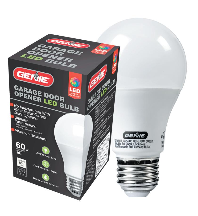
•If the lightbulb was the problem, a Genie lightbulb will resolve this issue
•If a NEW installation, check Door Arm position.
•Make sure ONLY the Safe-T-Beams® that came with this opener are installed.
•Check if limits are properly set. Adjust limits as needed.
•Check if Safe-T- Beam® red LED is flashing. It should be on steady.
•Check garage door for binding.
•If an operational problem exists, and opener will not close, the opener can be forced to close. Press and hold the wall control button until door is completely closed.
•Check for interference from adjacent photo eye sensors of any brand.
Door starts down, then STOPS before it is closed. OR Door will only open.
Door starts up, but STOPS before it is completely open.
Door will only run closed.
Door opener starts for no reason.
•Check Safe-T- Beam® wire connection at powerhead and at STBs.
•Check if limits are properly set. Adjust limits as needed.
•Check CONTACT REVERSE.
•Check garage door for binding.
•Check closing “FORCE” control.
•Check if limits are properly set. Adjust limits as needed.
•Be sure door, opener, springs are in good repair, properly lubricated and balanced.
•Check closing/opening “FORCE” control.
•Turn Sure-Lock™ OFF aka lock mode.
•Check if limits are properly set.
•Check door balance, condition, and door spring.
•Check opening “FORCE” control or Force settings.
•Button stuck on wall control or remote.
• Remote lost or stolen? Erase all remotes from powerhead and program new remotes. Noisy Operation.
Door opener runs slow.
•Be sure all door fasteners are tight.
•Be sure garage door is in good repair, properly lubricated and balanced.
•Check operating condition of door. Door may need professional repair.
•Is this opener installed on a one-piece door? Call the Genie technical line. Need
20
help or have
Call our
at
option 3.
any questions?
technical hotline
(800) 843-4084
Manually Adjusting Force for Unique Applications
TO AVOID INJURY OR DAMAGE
•NEVER adjust the force settings to adjust for damage, including an unbalanced door, binding door track or broken spring. Perform a CONTACT REVERSE TEST monthly.
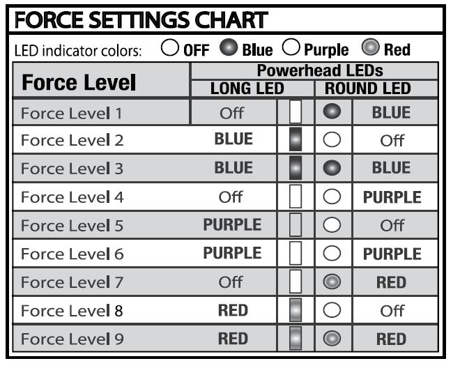
Force Settings
Force settings are pre-programmed at the factory and applied during the Open/Close Limit settings steps. For normal use, these settings should not need adjustments with this unit.
Conditions possibly requiring adjustments are:
1.A combination of: low-headroom track with an oversized wood door that has a windowed-top section.
2.Doors that start down, STOP, and reverse before closing.
3.Doors that start up, but STOP before they completely open.
Force Settings Chart
21
Manually Adjusting Force for Unique Applications
1. Press and hold both up and down arrow buttons until round LED turns Red, release button. Blue LED will flash 3 times.

LEDs will now display current UP force setting (See Chart).
2. Press either arrow button until desired UP force setting is reached (See chart).

3. Once setting is chosen, press and release. This will lock the UP force setting.
See Chart
LEDs will now show current DOWN force setting (See Chart).
4. Press either arrow button until desired DOWN force setting is reached (See Chart).


5. Once setting is chosen, press and release. This will lock the DOWN force setting.
6. The LEDs will now turn BLUE then off. This confirms that both force settings have been reset and unit is ready for normal operation.
See Chart
Set the Force Control. With the door engaged with the rail, cycle the operator a full open and closed cycle and complete a contact safety reversal test. Need help or have any questions? Call our technical hotline at (800) 843-4084 option
22
3.
Homelink® and Car2U®
Programming a Homelink® System
Programming a Car2U® System
Step 1 Clear Car2U to default settings
The default setting for the Car2U system is:
• Button 1 = Genie® Manufactured Openers

• Button 2 = LiftMaster® Manufactured Openers
Step 1 Clear HomeLink
Clear HomeLink by pressing and holding down the first and third buttons until the indicator on the HomeLink blinks slow and then fast for 20 seconds; then release both buttons.


NOTE: Clearing the HomeLink will remove all previously programmed garage door openers.
Step 2 Train HomeLink to the Genie Remote
Choose the button on the HomeLink to be used to open the door.
NOTE: Hold the Genie Remote two inches from the HomeLink button.
Hold down the Genie remote button. While holding, press and hold the chosen HomeLink button. Hold down both buttons until the indicator on the HomeLink blinks slow then fast. Once it blinks, release both buttons.
• Button 3 = Wayne Dalton® Manufactured Openers
A.Press and hold buttons 1 and 3 for 20 seconds or until all three LEDs begin to flash.
B.Release both buttons. The Car2U system is now set to the Factory Default settings.
NOTE: Clearing the Car2U system will remove all programmed garage door openers.
Step 2 Program Car2U to the Genie Opener
A.Press and hold the PRGRM SET button on the opener until the round blue LED is ON release the button. The long purple LED will begin flashing


Step 3 Program HomeLink to the Genie Opener
A.Press and hold PRGRM SET button on the opener until the round blue LED is ON. Release the button. The long LED will flash purple.
B.Press the designated Genie Car2U button for two seconds and release. Press that same button again for two seconds and release. At the powerhead, the long LED will flash blue and then turn off.
C.Press the Car2U button a few times more until door moves.
Step 3 Changing Factory Default Button for a Genie Opener
B.Press the chosen HomeLink button for two seconds and release. Press that same button again for two seconds and release. The long LED at the powerhead will flash blue and then turn off.
C.Press the HomeLink button a few more times until the door moves.
NOTE: For additional instructions, see the motor vehicle manual, www.homelink.com or visit www.GenieCompany.com
A.Press and hold buttons 1 & 3 for ONE SECOND and release all three LEDs will turn on solid red.
B.Press and hold the button (2 or 3) to change it to Genie the corresponding LED will flash. While continuing to hold that button press and release button 1. Press and release button 1 again.


C.Release the button being held in step B and wait for the LED to stop flashing. This button is now set for Genie. Repeat Step 2 for second Genie Opener.
NOTE: For additional instructions see the motor vehicle manual, learcar2u.com or visit www.GenieCompany.com
Need help or have any questions? Call our technical hotline at (800)
option 3. 23
843-4084
Wireless Keypad Intellicode®
Program the New Keypad to the Opener:
1. At the opener, press the PRGM SET button for two seconds, or until the round LED turns blue
2.On the Keypad enter the factory default code:
3. Press the Up/Down arrow key 3-4 times

4. The door should move; the keypad is now paired
5. To change the factory pin see "Change an Existing Pin/Change Factory PIN 3 5 7"
Change an Existing PIN/Change Factory PIN 357:
1. Enter the current PIN
2. Press the Program key one time
3. Key in the new PIN (3-8 digits)
4. Press the Program key one time
NOTE: Unlike “Erasing a PIN to Factory Setting,” there is no need to reprogram the opener after changing the PIN.
Opener
Models Follow the Same Steps
Watch "How to Program" video. Get the video using the QR Code to the left or click link below.

https://youtu.be/eKQdV_xWb74
Synchronizing Multiple Doors up to three: Whether the keypad is new or you are adding additional openers to an existing keypad, this step assumes that the above step "Program the New Keypad to the Opener" was completed


1. Key in the PIN on the keypad (3-8 digits).
2. Press the PROGRAM key two times.
24
(continued next page)
Wireless Keypad Intellicode®
Synchronizing Multiple Doors (Continued)

3. Press the number of doors the keypad will control (Up to 3. 2 or 3 accordingly).
4. Press the PROGRAM key. The keypad is now programmed for multiple signals.
5. At the power head press the PRGRM SET button for two seconds and the round LED turns blue. Then the long purple LED will flash.
6. Type the new PIN (3-8 digits).
7. Press the Up/Down key one time.
8. Assign a number to the door that the keypad will operate by pressing 1, 2 or 3.
9. Slowly press that door number two more times and the door will operate.
10. When the keypad turns dark, go back to step 5 to synchronize the additional doors.
To add another opener to a keypad that is already programmed to one opener, follow all the steps in the “Multiple Door Section”. The original opener programmed to the keypad is door #1.
Door Operation from the Wireless Keypad:
Single door:
1. Enter the PIN number
2. Press the Up/Down Key
Multiple doors:
1. Enter the PIN number
2. Press the Up/Down Key
3. Enter the door number (1, 2 or 3)
NOTE: The Keyless Entry Pad stays active for several seconds while lit and will stop or start the door with each touch of any button on the keypad.
Erasing a Keypad to Factory Setting:
1. Press and hold both the keypad PROGRAM key and the Up/Down key for about five seconds.
2. The Keypad LED will slowly blink and then turn off. The keypad is successfully erased.
3. To pair it with an opener, start with “Program the New Keypad to the Opener”.
Clearing the Genie Operator from all Remotes and the Wireless Keypad.
1.Press the PRGRM SET button at the powerhead for two seconds. The round LED turns blue.
2.Upon releasing, the long LED flashes purple.
3.Press and hold the up (+) and down (-) buttons at the same time until both LED lights blink blue.
Need help or have any questions? Call our technical hotline at (800) 843-4084 option 3.
25
Programming and Erasing Remote Controls
Press and Release the Learn code button once. The red LED will begin to flash. Go to Step 2.


The current single button remote will program to openers from 1995 to present.

1. Putting Opener Into Programming Mode:
2. Slowly press and release the remote button twice. The opener LEDs flash and go off, successfully synching. Pressing the button a third time, the door will cycle.
Lost or Stolen Remotes/Erasing All Remotes
A. Press and hold the program button until the round LED turns blue then release.

Press and hold the Program Set button until the round LED turns blue. Release.

B. Press and hold the up and down buttons at the same time until both LEDs flash blue and turn off.

The Long LED then Flashes Purple. Go to Step 2.
-OROpeners and Receivers Manufactured between 1995 to 2011.
-OROpeners and Receivers Manufactured between 1995 and 2011.
A. Press and hold the learn code button until the LED stops blinking. Need
843-4084
26
or have any questions? Call our
help
technical hotline at (800)
option 3.
Tips for the Dealer and Homeowner
1) Wi-Fi router needed: 802.11/b/g/n, 2.4GHz with WPA2 or WPA Security.
2) A strong Wi-Fi signal is needed in the garage, in order to pair with operator and cloud; at least two bars (-65dbm) otherwise a Wi-Fi extender may be needed from an electronics store.

3) a. Not for use with one-piece doors. b. Not for use on operators without photo eyes.
4) Aladdin Connect external device compatibility:
a. Compatible with Genie Series II operators. (Identified by the wall control buttons: white). All current models.
b. Not compatible with Genie Series III operators (Identified by the wall control buttons: black). An adapter is needed: Dry Contact Control Adapter #38013R.


5) Complete instructions included with manual or watch the video by scanning the QR code.


Tips to know for the Homeowner
1) Download the Aladdin Connect app: 2) Smartphone and/or tablet versions: a. Android 7.0 and higher b. Apple iOS 12.1 and higher

3) Follow the steps on the Aladdin Connect App a. Home Wi-Fi network name and password will be needed.
4) The Aladdin Connect serial number gets stored on one smartphone only (This user is the owner). All other users, up to 19 are invited by the owner after the set-up.
5) Aladdin Connect dedicated consumer line: (866) 599-4995 Monday to Friday 9:00am to 8:00pm EST. Saturday 10:00am – 6:00pm EST. Scan for the Aladdin Connect™ installation video

Scan here for additional Aladdin Connect™ information Aladdin


27
Connect for the consumer (866) 599-4995 Aladdin Connect for the GDO professional (800) 843-4084 option 5.
Understanding the LEDs & Troubleshooting

Depending on Model, these set of Wi-Fi buttons and their LEDs (#1 and #2) can be found on the outside, under the light cover, or under the programming cover.
Indicator LEDs Near the Operator's Wi-Fi Buttons: Blue (#1 above) and Grey (#2 above) - Defined

LED #1 Definitions Status
Solid RED Not Configured/Not Paired. (out of box from factory)
Solid BLUE Connecting to Wi-Fi. (occurs during configuration)
Solid GREEN
Flashing GREEN
“Timed Out” message on the app or The failure to progress from blue to green LED on the unit
Internet connected through local router to cloud service (normal operation).
The Wi-Fi signal to the router is good, but the device is not communicating to the cloud – can’t get past the router or the device is unable to establish a secure communication link to the cloud
a. Indicates an incorrect password has been entered for the home network router. – orb. Router does not have a strong enough signal in the garage to pass the connection message through to the cloud -or-
c. The smartphone is connected to the gdocntrl network, some phones discover that they can’t get to the internet through the gdocntrl network and switch back to cellular data automatically.
Perform configuration by following the steps in the app.
Normal process during configuration
Paired. No action required.
Check the internet connection on the router. Perform a factory reset. See #1 below.
a.Follow the instructions inside the app based on the indicator LEDs b. Move the router to get a stronger Wi-Fi signal or install a Wi-Fi extender.
c. The customer can try turning off cellular data on their smartphone.
Flashing BLUE
Operating in configuration access point (AP) mode and is ready for setup or is performing an OTA.
Wait up to 2 minutes to allow update to finish. LED stops flashing BLUE. Other
1. Factory Reset of the Wi-Fi Device – Press and hold the blue button (#1 in photo) until you hear 2 beeps. The LEDs start flashing and changing colors. Then press and hold the grey button (#2) until it beeps twice. The LEDs will still be flashing and changing colors. Note: The serial # must be deleted on the owner's Aladdin Connect® app and re-installed. (The Tech Line can also delete the serial number).
2. Customers using a Firewall at their router may wish to selectively open limited ports for our device. The DCM uses two IP ports, 123 and 443, for GDO Controller access to servers.
3. Manual Over the Air (OTA) Update - Not normally needed as the unit occasionally updates automatically but can be done manually for the latest Wi-Fi firmware. The LED #1 must be green or flashing green. Press and hold the MFi grey button (#2 in the photo) until it beeps twice. An OTA may take 2 to 5 minutes to complete. When the LEDs stop flashing the firmware update is complete.
17
28
Troubleshooting
Aladdin Connect for the consumer (866) 599-4995 Aladdin Connect for the GDO professional (800) 843-4084 option 5.
Options


Safe-T-Beam® Self-Diagnostic Troubleshooting Chart (Photocells) Genie’s Product Bulletin Updates: www.geniecompany.com/images/ODM/PIB/PIB.pdf Need help or have any questions? Call our technical hotline at (800) 843-4084 option 3. 29
brand.
2.Find the LEARN/PROG button on your deviceshape, color or name of this button could vary by
manufacturer of the opener/receiver.
opener/receiver, the instruction manual, the current remote controls for the opener, or the original
1.Locate the brand and opener/receiver specifications for your device by consulting the label on the
STEP 1FIND SPECIFICATIONS &
LEARN BUTTON
* Overhead Door® 390 MHz, 9 Switch/3 Position Dip Switch, 1993-1995
* Genie® 390 MHz, 9 & 12 Switch/2 Position Dip Switch, 1993-1995
*Stanley ® 310 MHz, 10 Switch/2 Position Dip Switch
* Chamberlain® 390 MHz, 9 Switch/3 Position Dip Switch
Marantec® 315 MHz, Fixed Learn Code 12
Xtreme® brand 303 MHz, Fixed Learn Code 11
Guardian® 303 MHz, Fixed Learn Code 11
Ryobi® 372.5 MHz, Rolling Code 10
Wayne Dalton® 372.5 MHz, Rolling Code, 1999-current 9
Linear® 318 MHz, Mega Code® 8
Sommer® 310 MHz, Rolling Code 7
Overhead Door® 315/390 MHz, CodeDodger® II, 2010-2011 6
Genie® 315/390 MHz, Intellicode® II, 2010-2011 6
Chamberlain® LiftMaster® CraftsMan®

Green Learn Button, Billion Code®, 1993-1995, 390 MHz 5
Yellow Learn Button, Security +2.0®, 2011-current, 390 MHz 4 4
Orange/Red Learn Button, Security +®, 1996-2005, 390 MHz 3 3
Purple Learn Button, Security +®, 2006-2014, 315 MHz 2 2
Overhead Door® 315/390 MHz, CodeDodger® I, 1995-current 1 1
Genie® 315/390 MHz, Intellicode® I, 1995-current 1 1
Specification Notes
Brand Name Garage Door Opener or Gate Receiver
A VAILABLE PROGRAM METHOD
and method, then proceed to STEP 1.
Instructions continue on next page.
trademarks are the property of their respective owners.
TIP: Allow the LED light on the universal transmitter to stop flashing before your next button press.
once every 2 seconds until the garage door opener operates. Programming is complete.
2.On the universal remote, press and release the pre-set button that corresponds with your opener
1.On the garage door opener, press the LEARN button for 2-3 seconds and then release.

If using Button 1, 2 or 3:
L earn Button instructions shown on the next page.
Button 4: Chamberlain® with a YELLOW LEARN Button*Move directly to Chamberlain® Yellow
Button 3: Chamberlain® with an ORANGE/RED LEARN Button
Button 2: Chamberlain® with a PURPLE LEARN Button
Button 1: Genie Intellicode 1 or Overhead Door CodeDodger I
Reference FIG 1 to use any of these four manufacturer pre-sets to quickly program a button.
OPTION
1: QUICK START METHOD
different brands of garage door openers and gate receivers.
desired button set-up. Each button can be programmed individually to operate up to 4
combination of options available for your opener/specification combination to achieve your
Review Chart A to find your specifications and available programming options. You can use any
STEP 3CHOOSE A
PROGRAMMING
OPTION
different programming modes.
will also light in response to button presses during
LEDThe LED will light with each button press and
Pre-set Button Number on Remote Number of
Button Presses
QUICK START METHOD LEARN METHOD
available methods that can be used to program them. Review Chart A for compatibility
Below are the brands and specifications that this remote is compatible with and the
UNIVERSAL REMOTE INSTRUCTIONS
FIG. 1
3 4
STEP 2BUTTON LAYOUT & LED 1 2
A Genie® and Intellicode® are registered trademarks of The Genie Company. All other listed names and 30
EXAMPLES :
to "Conversion Instructions for Genie Fixed Code"
Go
SIGNAL
PRGM SET RADIO
LEARN CODE CODE LEARN Gate Recievers
Chart
* For Marantec® openers, reference operator manual to program remotes to the operator head.
TIP: Allow the LED light on the universal transmitter to stop flashing before your next button h nical H otline for the GDO Pro : (800) 843-4084 option 3
until the garage door opener operates. Programming is complete.
7.On the garage door opener, press the LEARN button for 2-3 seconds and then release.
continue below.
YELLOW LEARN button instructions shown right. If using ANY OTHER brand/specification, please
**If using Chamberlain with Yellow LEARN button, please move directly to the Chamberlain®
6.Wait the remainder of the 15 secondsthe BLUE LED will give a long blink and then go out.
this QR code to watch the "How to Program" video. (It doesn't include dip switches.) Tec

1.You will have 15 seconds to complete this task.
5.On the universal remote, press the button of your choice the required number of times from Step
4.Release both buttonsthe BLUE LED on the remote will begin flashing.
3.While still holding down button #2, press button #4 on the universal remote four times.
2.On the universal remote, press and hold down button #2. (Reference FIG. 1)
your brands/specification in Chart A.
1.Find and remember the required number of button presses in the LEARN METHOD column next to
In this method, your universal remote will learn which specification you want it to work with.
OPTION 2: LEARN METHOD
clearing at the opener head will clear all devices that are currently programmed.
transmitters from the head. Please consult your opener manual for instruction. In most situations,
If the above does not work, clear the remote in the same manner that you would clear the original
blue LED will give a long blink and then go out.
On the universal remote, press and hold down button #3 while pressing button #4four times. The
Clearing the Universal Remote
:
button press.
TIP: Allow the LED light on the universal transmitter to stop flashing before your next
The next button press should operate the opener.
5. On remote, press button you chose again ONE time. Opener will click again.
4. On opener, press LEARN/PROGRAM button again for 2-3 seconds and then release.
3. On remote, press button you chose ONE time. Opener will click.
2. On opener, press LEARN/PROGRAM button for 2-3 seconds and then release.
1. Press and hold down the button #4 for 5 secondsrelease button after white LED blinks 3
If using Button 4 for a YELLOW LEARN Button from Chamberlain, LiftMaster or Craftsman:
QUICK START METHODYELLOW LEARN BUTTON
TIP: Allow the LED light on the universal transmitter to stop flashing before your next button press.
10. Test the buttonprogramming is complete.
9. Press the button you chose ONE time again. Opener will click again.
8. On the opener, press the LEARN/PROGRAM button again for 2-3 seconds then release.
7. On remote, press button you chose ONE time. Opener will click.
6. On opener, press LEARN/PROGRAM button for 2-3 seconds and then release.
times and goes out.
5. Press and hold down same button you chose for 5 secondsrelease button after WHITE LED blinks 3
times and goes out.
UNIVERSAL REMOTE INSTRUCTIONS continued
long blink and goes out.
4. On remote, press button of your choice four timeswait remainder of 15 secondsBLUE LED gives
3. Release both buttonsBLUE LED will begin flashing.
2. While still holding down button #2, press button #4 on remote four times.
press. Sc an Consumer line for the homeowner (800) 354-3643 [800 354-GENIE] 31
ID# 4 ONLY: Chamberlain®/LiftMaster®/Craftsman® Y ellow Learn Button Inst.
8.On the universal remote, press and release the button you just programmed once every 2 seconds
LEARN METHOD (RECOMMENDED)
1. On remote, press and hold down button #2. (Reference FIG. 1)
If the opener has a group of switches with 3 positions per switch (TRINARY):
Switch in the UP (+) position = press button 1
Switch in the MIDDLE (0) position = press button 2
Switch in the DOWN (‐) position = press button 4
In this example, the code would be:
If the opener has a group of switches with 2 positions per switch (BINARY):


Switch in the UP (+) position = press button 1
Switch in the DOWN (‐) position = press button 4

In this example, the code would be:


Step 1: Record Switch Positions
Each shaded box below represents a switch position. In these boxes, write in the number 1, 2 or 4 as it corresponds to the +, 0, or – switch position shown on the remote, opener or receiver. If you have less than 12 switches, only fill in what you have. You will reference this section in STEP 3.4 below.

Step 2: Determine Specifications

Find your specification from CHART B below and record the number here: This box should say 1, 2, 3, 4 or 5. You will reference this in STEP 3.9below.
Available in remotes with software REVs v1.1.4 and higher. Look at back of remote for this number. *
Step 3: Programming
ENTER LEARN MODE:
1.On the universal remote, press and hold down button #1.
2.While still holding down button #1, press button #4 on the universal remote four times.
3.Release both buttons ‐ The WHITE LED on the remote will quickly flash 4 times.
ENTER DIP SWITCHES:
4.On the universal remote, enter in order the numbers 1, 2 or 4 as you have written in STEP 1. The LED lights with each button press.

5.After the last DIP switch position entry, simply wait for the BLUE LED to quickly flash 4 times and go out.
ENTER BUTTON SELECTION MODE:
6.On the universal remote, press and hold down button #2.
7.While still holding down button #2, press button #3 on the universal remote four times.
8.Release both buttons ‐ the BLUE LED on the remote will begin flashing.
9.Press the button of your choice on the universal remote the required number of times indicated from Chart B in STEP 2 above. You will have 10 seconds to complete your entry.
10.After your press(es), simply wait the remainder of the 10 seconds ‐ the BLUE LED will give a long blink and then go out.
32 DIP SWITCH / FIXED CODE PROGRAMMING
TEACH & PAIR PROGRAMMING METHOD
Available in remotes with software REVs v1.1.8 and lower (also allows FAAC receiver compatibility)
IMPORTANT: For ID#4 Chamberlain®/LiftMaster®/Craftsman® Yellow Learn Button ‐ move immediately to instructions on the right side. For all other ID#s, proceed with instructions on the left.
TEACH & PAIR PROGRAMMING METHOD
for all openers EXCEPT ID#4 Yellow Learn Button
1.1. On universal remote, press and hold down button #1
2.While still holding down button #1, press button #2 on universal remote four times
3.Release both buttons ‐ WHITE LED will begin flashing slowly.
4.Place the existing, operational remote and universal remote within 4” of each other
5.Hold down the operational button from the original remote. Do not release until the new universal remote blinks change from slow WHITE blinks to rapid BLUE blinks. You will have 20 seconds to complete.
TIP: If the universal remote does not recognize the transmission, try different distances between 0”‐4” away from the side of the universal remote closest to button numbers 1 and 3.
6.Once the universal remote BLUE LED is blinking rapidly, press the button of choice on the universal
7.remote ONE TIME slowly and deliberately. The BLUE LED will turn solid and go out.
8.On opener, press LEARN/PROGRAM button for 2‐3 seconds and then release.
9.Press and release button you just programmed once every 2 seconds until the garage door opener operates.
10.Test the button ‐ programming is complete. TIP: Allow the LED light on the universal transmitter to stop flashing before your next button press.
TEACH & PAIR PROGRAMMING METHOD for ID#4 Chamberlain®/LiftMaster®/Craftsman®Yellow Learn Button ONLY
1.1 On universal remote, press and hold down button #1.
2.While still holding down button #1, press button #2 on universal remote four times.
3.Release both buttons ‐ WHITE LED flashes slowly.


4.Place the existing, operational remote and universal remote within 4” of each other.
5.Hold down the operational button from the original remote. Do not release until the new universal remote blinks change from slow WHITE blinks to rapid BLUE blinks. You will have 20 seconds to complete. TIP: If the universal remote does not recognize the transmission, try different distances between 0”‐4” away from the side of the universal remote closest to button numbers 1 and 3.
6.Once the universal remote BLUE LED is blinking rapidly, press the button of choice on the universal
7.remote ONE TIME slowly and deliberately. The BLUE LED will turn solid and go out.
8.Press and hold down the button you just chose on the universal remote for 5 seconds.
9.Release button after white LED blinks 3 times and goes out.
10.On opener, press LEARN/PROGRAM button for 2‐3 seconds and then release.
11.On remote, press button you chose ONE time. Opener will click.
12.Repeat STEPs 9 & 10.
13.Test the button ‐ programming is complete.
TIP: Allow the LED light on the universal transmitter to stop flashing before your next button press.
33
Keypad Overview
STEP 1 - FIND SPECIFICATIONS & LEARN/PROGRAM BUTTON
RADIO SIGNAL LEARN CODE Keypad Up/Down Key (enter) Program Key LED LED O LED On LED Flashing Keypad O Keypad OnKeypad Flashing
1. Locate the brand and opener/receiver specifications for the device by consulting the label on the opener/receiver, the instructions manual, the current remote controls for the opener, or the original manufacturer or the opener/receiver.
2. Find the LEARN/PROGRAM button on the device - shape, color or name of this button could vary by brand. For garage door openers, be sure to check under the light covers. For commercial openers, this button may be on the circuit board or the opener. In some cases, this button could also be on an external receiver that is mounted on or nearby the product. Consult the devices manual if needed.
• An audible beep will sound with every key pressed.
• Keypad will operate up to 3 doors with one PIN number.
• A temporary PIN can be set for convenient non user access.
Below are the brands and specifications that this keypad is compatible with. Find the ID# in Chart A below that references your specific opener specification. You will need this number during programming. Refer to STEP 1 to find the type and/or LEARN/PROGRAM button.
Chart A
1
Keypad LED’s Successful Entries
Purple Learn Button, Security +®, 2006-2014, 315MHz
Chamberlain® LiftMaster® Craftsman®
Keypad LED will flash and beep each time a key is pressed and entry is accepted.
Keypad LED and PROGRAM key will flash slowly and number pad back light will remain on for 15 seconds indicating a successful program or valid PIN has been entered.
34
Orange/Red Learn Button, Security+®, 1996-2005,390MHz
Yellow Learn Button, Security + 2.0®, 2011-current, 390MHz
Green Learn Button, Billion Code®, 1993-1995, 390MHz
Genie® 315/390 MHz, Intellicode®II, 1995-current

Overhead Door® 315/390 MHz, CodeDodger® II, 1995-current
Sommer® 310 MHz, Rolling Code
2
3
4
5
6
6
7
8
9
10
11
11
12
21 *Genie® 390
12
22 390
23 *Stanley®
31 *Overhead
32 *Chamberlain®
FCC Part 15.21 Statement: Changes or modifications not expressly approved by the party responsible for compliance could void the user’s authority to operate the
Genie® and
are registered trademarks of The Genie Company. All other listed names and trademarks are the property of their respective owners. PRGM SET CODE LEARN Receivers E
ID# Brand Garage Door Opener Specification Notes 1 Genie® 315/390 MHz, Intellicode® I, 1995-current :
Overhead Door® 315/390 MHz, CodeDodger® I, 1995-current
Linear® 318 MHz, MegaCode®
Wayne Dalton® 372.5 MHz, Rolling Code, 1999-current
Ryobi® 372.5 MHz, Rolling Code
Guardian® 303 MHz, Fixed Learn Code
Xtreme® brand 303 MHz, Fixed Learn Code
Marantec® 315 MHz, Fixed Learn Code
MHz,
Switch / 2 Position Dip Switch*
MHz, 9 Switch / 2 Position Dip Switch*
310MHz, 10 Switch/2 Position Dip Switch*
Door® 390 MHz, 9 Switch / 3 Position Dip Switch*
390 MHz, 9 Switch / 3 Position Dip Switch*
equipment.
Intellicode®
xamples
Universal Keypad Instructions
DIP switch models are noted with an asterisk* - after STEP 2 in this instruction,- skip to the pages on Dip Switch Instructions for the Universal Keypad or visit www.geniecompany.com/dipswitchesGUK
IMPORTANT FEATURES OF THIS KEYPAD:
• Do not press the LEARN button for longer than the noted 2-3 seconds as it could cause the operational remotes to no longer work.
Universal Keypad Instructions continued
STEP 2 - CLEARING THE KEYPAD
Perform this task first before setting the PIN or at anytime the keypad needs to be reset to its factory default:
1. Remove activation tab from inside battery compartment.
2. Press both the PROGRAM & UP/DOWN keys at the same time and hold for 5 seconds. (tone will sound) - then release (green LED will flash and go out).
3. The keypad is now ready to be programmed. Start at STEP 3.If the opener/receiver has dip switch technology, please move to the alternate instructions listed in the next pages.
STEP 3 - PROGRAMMING TO ONE OR MORE OPENERS
This keypad can be programmed to up to 3 individual garage door openers in any combination of manufacturer specifications. You will need your opener ID# from Chart A for these steps. To start over at any time, start at STEP 2 - CLEARING THE KEYPAD.
PROGRAM OPENER #1
NOTE: PROGRAM OPENER #1 (For all openers EXCEPT ID#4 Yellow Learn ButtonChamberlain®/LiftMaster®/Craftsman®)
1. On the keypad, enter a personal PIN (3-8 digits).
2. On the keypad, press and release the UP/DOWN key (LED flashes slowly).
3. On the keypad, enter the ID# of the opener from Chart A.
4. On the keypad, press and release the UP/DOWN key (LED flashes rapidly).
5. On the opener, press the LEARN/PROGRAM button for 2-3 seconds and then release.
6. On the keypad, press the UP/DOWN key once every two seconds until the opener operates. Let it run until it stops.
TIP: As soon as the opener activates, DO NOT press any additional buttons until the opener stops running.
ONLY IF YOU HAVE A Chamberlain®/LiftMaster®/Craftsman® opener with a YELLOW LEARN button.
1.On keypad, enter personal PIN (3-8 digits).
2.On keypad, press and release UP/DOWN key (LED flashes slowly).
3.On keypad, enter the ID#: 4
4.On keypad, press and release UP/DOWN key (LED flashes rapidly).
5.Then press and hold down UP/DOWN key.
6.Release button after tone sounds (5 sec).
7.On opener, press LEARN/PROGRAM button 2-3 seconds and then release.
8.On keypad, press UP/DOWN key ONE time. Opener will click.
9.On opener, press LEARN/PROGRAM button 2-3 seconds again and then release.
10.On keypad, press UP/DOWN key again ONE time. Opener will click.
11. On keypad, press UP/DOWN key again ONE time. Opener will operate.
12.WAIT until backlighting is out before attempting additional keypad entries. Programming is complete.
MULTIPLE OPENERS:
Complete steps for Opener #1 above. To program Opener #2 or #3 at any time, follow the steps below. Be ready to reference Chart A and then #3 from above.
1 With keypad backlighting off, press the PROGRAM button 2 times to program a second opener OR press it 3 times to program a third opener (blue LED flashes slowly). With blue LED still flashing, return to #3 in the section above and enter its opener ID# from CHART A. Continue with the remaining numbered steps.
STEP 4 - USING THE KEYPAD TO OPERATE OPENERS
1.Ensure number pad back lighting is off.
2.Enter PIN.
3.Press the UP/DOWN key.
4.Opener will operate.
1.Ensure number pad back lighting is off.
2.Enter PIN.
3.Press the UP/DOWN key.
4.Press number key corresponding with desired door (1, 2, or 3).
5.Desired opener will operate.
ADDITIONAL PROGRAMMING
SETTING A TEMPORARY MAIN PIN:
If the keypad is to be used by normally unauthorized personnel (such as a repairman) a temporary PIN can be assigned to that personnel to gain access to the garage. This PIN will remain active until the main PIN is used again. (PRGM = PROGRAM).
1. Enter main PIN.
2.Press PRGM key three times (LED will turn solid indicating keypad is ready for temporary PIN).
3.Enter temporary PIN (3-8 digits).
4.Press PGRM key one time (LED will blink twice and go out indicating a temporary PIN is set).
5.To cancel the temporary PIN, operate the keypad/door with the original main PIN.
CHANGE PIN:
If the main PIN needs changed, follow these steps.
1.Enter current main PIN.
2.Press PRGM key one time (LED will turn solid indicating keypad is ready for new PIN).
3.Enter new PIN (3-8 digits).
4.Press PGRM key one time (LED will blink twice and go out indicating a new PIN is set).
MOUNTING KEYPAD/REPLACING BATTERIES
Keypad MUST be mounted within sight of the garage door(s) at least 5 feet above floor and clear of any moving door parts. NOTE that programming will not be lost during battery removal.
To see a video on "How to Program the Universal Keypad" point your smartphone at the QR code or copy the link below to go to the site.
https://youtu.be/dM5fs_4-G4Y

35
Need help or have any questions? Call our technical hotline at (800) 843-4084 option 3.
SINGLE DOOR OPERATION: MULTI-DOOR OPERATION:
UNIVERSAL KEYPAD INSTRUCTIONS FOR DIP SWITCH COMPATIBLE MODELS
This is a Universal Keypad supplemental instruction for dip switch compatible operators. Use this in place of Step 3 of the main instruction. Reference the main instruction for all other keypad features and functions.
What do fixed code dip switches look like and how to convert them for programming the Universal Keypad?The DIP SWITCHES will be located on the garage door opener motor head or inside the remote control.
If the opener has a group of 9 switches with 3 positions per switch (TRINARY):
• Switch in the UP (+) position = Press button 1
• Switch in the MIDDLE (0) position = Press button 2
• Switch in the DOWN (-) position = Press button 3
In this example, the code would be:
If the opener has a group of 9-12 switches with 2 positions per switch (BINARY): + -
1 2 3 4 5 6 7 8 10 11 12
• Switch in the UP (+) position = Press button 1
• Switch in the DOWN (-) position = Press button 2
In this example, the code would be:
2 1 1 1 1 1 1 1 2 2 2 2 + 01 2 3 5 6 7 8 3 3 1 1 1 1 1 2 2
ID# Brand Name Garage Door Opener Specification Notes 21 *Genie® 390 MHz, 12 Switch / 2 Position Dip Switch* 22 390 MHz, 9 Switch / 2 Position Dip Switch* 23 Stanley® 310 MHz, 10 Switch/ 2 Position Dip Switch* 31 *Overhead Door® 390 MHz, 9 Switch / 3 Position Dip Switch* 32 *Chamberlain® 390 MHz, 9 Switch / 3 Position Dip Switch* All listed names and trademarks are the property of their respective owners.
1: Find and notate DIP SWITCH positions
2: Find and notate opener ID#(s) Opener ID# Opener 1 Opener 2 Opener 3 Below are the DIP switch model brands and specifications that
that references the specific opener specification.
Each
box below represents a DIP switch position.
corresponds to the +, 0, or - switch
the code
Convert
Convert
36
STEP
STEP
this keypad is compatible with. Find the ID# in Chart B below
CHART B
shaded
In these boxes, write in the number 1, 2 or 3 as it
position shown on the remote, opener or receiver. You will need to reference this section in STEP 3 later. (Not all boxes will be used when working with 9 switch openers). Convert
for opener #1:
the code for opener #2:
the code for opener #3: Write ID#(s) Here. You will need to reference this section in STEP 3 later.
STEP 3: PROGRAMMING TO ONE OR MORE OPENERS
This keypad can be programmed to up to 3 individual garage door openers in any combination of manufacturer specifications. Converted code(s) and opener ID#(s) from STEPS 1 & 2 are required to complete these steps.
Program Opener #1:
1.On the keypad, enter a personal PIN (3-8 digits).
2.On the keypad, press and release the UP/DOWN key (LED flashes slowly).
3.On the keypad, enter the ID# from CHART B
4.On the keypad, press and release the UP/DOWN key (LED flashes quickly).
5.Enter the converted code from Step 1 on first page for opener 1.
6.On the keypad, press the UP/DOWN key once every two seconds until the door operates.
Programming is complete for a single dip switch opener. To program additional dip switch openers at any time, see steps listed below.
Note: Converted codes and ID#s for the additional openers are required to complete the next section.
Programming Multiple Openers:
Complete steps for Opener #1 above. To program Opener #2 or #3 at any time, follow the steps below with backlighting off. Be ready to reference the converted codes and ID#s from Steps 1 and 2 in this document.
1.On the keypad, press the PROGRAM button 2 times to program a second opener OR press it 3 times to program a third opener (LED flashes slowly).
2.On the keypad, enter ID# of opener from Chart B for Opener #2 or #3.
3.On the keypad, press and release the UP/DOWN key (LED flashes quickly).
4.Enter the converted code from Step 1 on first page for Opener #2 or #3.
5.On the keypad, press the UP/DOWN key once every two seconds until the door operates.
STEP 4: USING THE KEYPAD TO OPERATE OPENERS
Single Door Operation:
1.Ensure number pad back lighting is off.
2.Enter PIN and press the UP/DOWN key (opener operates).
Multi-Door Operation:
1.Ensure number pad back lighting is off.
2.Enter PIN and press the UP/DOWN key.
3.Press number key corresponding with desired opener (1, 2, or 3).
4.Desired opener will operate.
For additional programming options and mounting instructions, refer to the main instruction sheet.
For questions, comments or troubleshooting, contact Customer Care by the phone number or web address listed on the main instruction sheet. You may also go to www.geniecompany.com
Need help or have any questions? Call our technical hotline at (800) 843-4084 option 3.
37
Universal Wireless Wall Console Instructions
Chart A
FIG. A
Delay Button Door Buttons
Open battery cover and remove battery tab before programming.
LED Signals:
- LED Blue blink indicates NORMAL status
- LED Red blink indicates LOW BATTERY
- LEDs will vary during programming
THINGS TO KNOW BEFORE STARTING:
•For use only with garage door operators complying with UL 325, manufactured after 1993 with working photo eyes installed.
•During programming, the garage door opener may operate.
•Do not press the LEARN button for longer than the noted 2-3 seconds as it could cause the existing, operational remotes and keypads to no longer work.
•All DOOR buttons are factory set to Genie Intellicode® 1.
Chart A lists the brands and specifications that this console is compatible with. Find the ID# in Chart A that references your specific opener specification. You will need this number during programming. Refer to STEP 1 to find the type and/or LEARN/PROGRAM button.

STEP 1 - FIND SPECIFICATIONS & LEARN BUTTON
1.Locate the brand and opener/receiver specifications for your device by consulting the label on the opener/ receiver, the instruction manual, the current remote controls for the opener, or the original manufacturer of the opener/receiver.
2.Find the LEARN/PROG button on your device - shape, color or name of this button could vary by brand. For garage door openers, be sure to check under the light covers. For commercial or gate openers, this button may be on the circuit board of the opener. In some cases, this button could also be on an external receiver that is mounted on or nearby the product. Consult the devices manual if needed.
EXAMPLES:
*For Marantec® openers, reference operator manual to program remotes to the operator head.
9
Screw Slot
Rear
PRGM SET RADIO SIGNAL LEARN CODE CODE LEARN Gate Receivers
the
Scan QR for
38
Continued on
next page
instructions & video
Universal Wireless Wall Console Instructions
Continued
STEP 2 - PROGRAMMING - UNIVERSAL WIRELESS WALL CONSOLE
IMPORTANT: For ID#4 Chamberlain®/LiftMaster®/Craftsman® Yellow Learn Button - move immediately to the proper section below. For all other ID#s, proceed to LEARN METHOD section.
LEARN METHOD (RECOMMENDED PROGRAMMING)
Review Chart A to find your specifications and available programming options. Each button can be programmed individually to operate up to 3 different brands of garage door openers and gate receivers.
1.Remove activation tab from inside battery compartment.
2.Find and remember the required number of button presses (ID#) in the LEARN METHOD column next to your brands/specification in Chart A.
REMEMBER: For ID#4 Chamberlain®/LiftMaster®/Craftsman® Yellow Learn Button ONLY - move immediately to instructions below. For all other ID#s, proceed to step 3.
4. Press and hold down the DELAY button until ALL 3 BLUE LEDs start blinking and then release (@5 sec.) Press the DOOR button of your choice the required number of times from Step 1 (Chart A). TIP: You may program all 3 DOOR buttons at one time if preferred. The DELAY button press will signal completion for all buttons.
3.
5.Press the DELAY button one time to signal the entry is complete.
6.On the opener, press the LEARN/PROGRAM button for 2-3 seconds then release.
7.Press the DOOR button you just programmed once every two seconds until the opener operates.
8.When the door stops moving, press the DOOR button again to test. Programming is complete.
ONLY for ID#4 Chamberlain®/LiftMaster®/Craftsman® Yellow Learn:
1. Remove activation tab from inside battery compartment
2.
3. Press and hold down the DELAY button until ALL 3 BLUE LEDs start blinking and then release (@5 sec.) Press the DOOR button of your choice four times.
TIP: You may program all 3 DOOR buttons at one time if preferred. The DELAY button press will signal completion for all buttons.
4. Press the DELAY button one time to signal the entry is complete.
5. Press and hold down the DOOR button you just chose until the red LED in the top button blinks and goes out (@5 sec.).
6. On the opener, press the LEARN/PROGRAM button for 2-3 seconds then release.
7. Press the door button you chose ONE time. Opener will click.
8. On the opener, press the LEARN/PROGRAM button again for 2-3 seconds then release.
9. Press the door button you chose ONE time again. Opener will click again.
10. Press the DOOR button again and the opener will activate.
11. When the door stops moving, press the DOOR button again to test. Programming is complete.
STEP 3 - OPERATING THE WALL CONSOLE
Operating a Door:
1. Press and release the door button of your choice. The door will move up or down.
To initiate the DELAY feature on any DOOR button:
Note: Safety sensor override operation will not work with this console
1. Press and release the DELAY button one time, two times or three times for a delayed door movement.
2. Press and release the DOOR button of your choice. Activation will be delayed by 10, 15 or 20 seconds. Need help or have any questions? Call our technical hotline at (800) 843-4084 option
3. 39
ALTERNATE INSTRUCTIONS
UNIVERSAL WIRELESS WALL CONSOLE
Alternate instructions for the Teach & Pair Programming Method, for Fixed Code/Dip Switch Programming and alternate blink rates are to be used in conjunction with the main instruction set.
Page 40: Changing Blink Rate Patterns Page 41: Fixed Code/Dip Switch Programming Page 42: TEACH & PAIR Programming Method
BLUE LED Blink Rate Mode 1: Factory Default Setting
(Blink Rate ‐ Once every 3 sec)
With only (1) AAA battery installed ‐ hold down the TOP DOOR button while simultaneously installing the second AAA battery. Continue to hold the TOP DOOR button for a total of 10 seconds until the blue LEDs on the OTHER 2 BUTTONS blink 3 times in unison.
BLUE LED Blink Rate Mode 2
(Faster Blink Rate ‐ Once every 2 seconds)


With only (1) AAA battery installed ‐ hold down the MIDDLE DOOR button while simultaneously installing the second AAA battery. Continue to hold the MIDDLE DOOR button for a total of 10 seconds until the blue LEDs on the OTHER 2 BUTTONS blink 3 times in unison.
BLUE LED Blink OFF Mode 3
(Blue LED OFF ‐ Maximum Battery Life) With only (1) AAA battery installed ‐ hold down the BOTTOM DOOR button while simultaneously installing the second AAA battery. Continue to hold the BOTTOM DOOR button for a total of 10 seconds until the blue LEDs on the OTHER 2 BUTTONS blink 3 times in unison.
Changes made to the blue LED blink rate pattern will impact battery life. For best battery life, see Blink Rate Mode 3 to turn LEDs off completely.
ALTERNATE INSTRUCTIONS
40
CHANGING BLINK RATE PATTERNS
If the opener has a group of switches with 3 positions per switch (TRINARY):
Switch in the UP (+) position = press button 1
Switch in the MIDDLE (0) position = press button 2
Switch in the DOWN (‐) position = press button 3
In this example, the code would be:
If the opener has a group of switches with 2 positions per switch (BINARY):

Switch in the UP (+) position = press button 1
Switch in the DOWN (‐) position = press button 3

In this example, the code would be:


Step 1: Record Switch Positions
Each shaded box below represents a switch position. In these boxes, write in the number 1, 2 or 3 as it corresponds to the +, 0, or – switch position shown on the remote, opener or receiver. If you have less than 12 switches, only fill in what you have. You will reference this section in STEP 3.5 below.
Step 2: Determine Specifications
Find your specification from CHART B below and record the number here: This box should say 1, 2, 3, 4 or 5. You will reference this in STEP 3.3 below.
Step 3: Programming
1. Remove activation tab from inside battery compartment.
ttons: 1
2. Press and hold down the DELAY button for @10 seconds until only a green LED lights on the top button ‐ then release. The green LED will continue flashing.
3. Press your DOOR button of choice the required number of times that corresponds with your opener from Chart B above (recorded answer from STEP 2).
4. Press the DELAY button one time to signal the entry is complete. The green LED will blink rapidly indicating it is ready to receive the recorded switch positions from STEP 1.
5. Enter the switch positions that you determined in STEP 1 above (a series of DOOR button presses – 1, 2 or 3).

6. After entering the final switch position, press and release DELAY button ONE time the entry is complete.
7. Test the button – the next DOOR button press should activate the opener.
ALTERNATE INSTRUCTIONS
DIP SWITCH / FIXED CODE PROGRAMMING
41
DOOR Bu
2 3 DELAY Button FIG A See FIG A See FIG A
ALTERNATE INSTRUCTIONS TEACH & PAIR PROGRAMMING METHOD
Review Chart A from the main printed instruction to find your specifications and available programming options.
IMPORTANT: For ID#4 Chamberlain®/LiftMaster®/Craftsman® Yellow Learn Button ‐ move immediately to instructions on the right side. For all other ID#s, proceed with instructions on the left.
TEACH & PAIR PROGRAMMING METHOD
for all openers EXCEPT ID#4 Yellow Learn Button
1.Remove activation tab from inside battery compartment
2.Press and hold down DELAY button until only a red LED lights on top button – then release (@15 sec).
3.Place the existing operational remote 1.5”‐ 3” away from the front of the universal wireless wall console.
4.Press and hold down a button from the original remote. Do not release until the new universal wireless wall console changes from SLOW red blinks to RAPID red blinks. You will have 20 seconds to complete.
TIP: If the console does not recognize the transmission, try pressing the original remote button for periods of 10 seconds at a time while trying different distances between 1.5”‐3” away from the front of the console.
5.When the wall console changes to RAPID red blinks, press the DOOR button of choice on the console ONE TIME. The red LED will turn solid and then go out.
6.On the opener, press the LEARN/PROGRAM button for 2‐3 seconds then release.
7.Press the DOOR button you just programmed once every two seconds until the opener operates.
8.When the door stops moving, press the DOOR button again to test. Programming is complete.
TEACH & PAIR PROGRAMMING METHOD for ID#4 Chamberlain®/LiftMaster®/Craftsman®Yellow Learn Button ONLY
1.Remove activation tab from inside battery compartment
2.Press and hold down DELAY button until only a red LED lights on top button – then release (@15 sec).
3.Place the existing operational remote 1.5”‐ 3” away from the front of the universal wireless wall console.
4.Press and hold down a button from the original remote. Do not release until the new universal wireless wall console changes from SLOW red blinks to RAPID red blinks. You will have 20 seconds to complete.
TIP: If the console does not recognize the transmission, try pressing the original remote button for periods of 10 seconds at a time while trying different distances between 1.5”‐3” away from the front of the console.

5.When the wall console changes to RAPID red blinks, press the DOOR button of choice on the console ONE TIME. The red LED will turn solid and then go out.
6.Now, press and hold down the DOOR button you just programmed until the red LED in the top button blinks and goes out (@5 sec.)
7.On the opener, press the LEARN/PROGRAM button for 2‐3 seconds then release.
8.On the console, press the DOOR button you chose ONE time. Opener will click.
9.On the opener, press the LEARN/PROGRAM button again for 2‐3 seconds then release.
10.On the console, press the DOOR button you chose again ONE time. Opener will click again.
11.Press the DOOR button again and the opener will activate.
12.When the door stops moving, press the DOOR button again to test. Programming is complete.
42
Drum Selection Settings for Wall Mount


Drum selection settings are pre-programmed at the factory for 4" standard Lift type drums (red setting). There are only two drum settings for sectional doors red and purple. Drum selection must be done for doors with Standard or High Lift drums with a diameter greater than 4 inches (purple setting) and also on Vertical Lift doors (purple setting). Proper selection of drum type is important for proper operation of the opener.
To Change Opener Drum Selection:
1. Press and hold the SET/PRGM button on the opener until both LEDs turn BLUE then release.
2. Press the UP button twice.
3. Press PRGM button once.

4. The current factory setting displays RED.
5. Press either UP or DOWN button one time to change setting to PURPLE.
6. Press PGRM button once to lock in PURPLE setting. LEDS turn BLUE then off.
7. Opener is now ready to set limits followed by two complete cycles for force and Safe-T-Pulse profiling.


Genie Tech: Video Library for the Garage Door Professional
www.geniecompany.com/professional-line-videos
Go to the website by scanning the QR code with your smartphone. The password to enter the site is:

943
GenieTechVideos
Changing the Speed Setting - 140V DC Motors* PRGM SET
Speed Settings (*Speed adjustment doesn't exist for model 3024 and One-piece doors induce a slower speed.) Speed settings are pre-programmed at the factory for maximum speed. Travel speed for the opener can be adjusted to a slower speed in both Open and Close directions, minimizing wear on heavier sectional doors. There are three speed settings. Please note that speed may be affected by door weight, balance, door components and tracks.
To Change Opener Speed Setting:
1. Press and hold the SET/PRGM button on the opener for 10 seconds, both LEDs turn BLUE then release.

2. Press the UP button twice.
3. Press PRGM button once.
4. The Open speed will now be displayed (Current setting displays RED = High)
5. Press the DOWN button one or two times to adjust UP speed. (PURPLE=Medium; Blue=Low)
6. Press PGRM button once to lock in the selected setting. The Close speed is also displayed.

7. Press DOWN button on or two times to adjust Close speed. (PURPLE=Medium; Blue=Low)
8. Press the PGRM button once to lock in the selected setting. Both LEDs flash blue to confirm.
9. Opener is now ready to set limits followed by one full cycle for force profiling.
Configuraciones de Velocidad - 140V DC Motors*
Configuraciones de Velocidad (*No existe para el modelo 3024. Puertas de una pieza provocan una velocidad más lenta.)
Las configuraciones de velocidad ya son programadas en la fábrica para la máxima. Sin embargo, la velocidad de desplazamiento puede ser ajustada para una velocidad más lenta en ambas direcciones de Apertura y Cierre, para minimizar el desgaste en las puertas seccionales más pesadas. Existen tres configuraciones de velocidad disponibles para las puertas seccionales. Por favor note que la velocidad podrá ser afectada por el peso y balance de la puerta junto con las condiciones de los componentes y los rieles.
1. Oprima y sostenga durante 10 segundos o hasta que ambas luces LED se vuelvan de color azul.
2. Oprima la tecla apuntada hacia Arriba dos veces.
3. Oprima la PRGM una vez.
4. La velocidad actual para el desplazamiento de APERTURA será desplegada. (Rojo = Alta)
5. Oprima la tecla apuntada hacia abajo de hasta dos veces para reducirla. (Morado=Media; Azul=Baja)
6.Oprima y suelte la PGRM una vez. La configuración actual del CIERRE se despliega.
7.Oprima la de hacia abajo una o dos veces para reducir la velocidad de cierre. (Morado=Media; Azul=Baja)
8.Oprima y suelte la PRGRM, Ambas luces LED parpadearán el color AZUL para confirmar la configuración.
9.Haga una reconfiguración de los límites de desplazamiento y realice un ciclo completo.
44 English & español
Tipo 1 Tipo 2 Tipo 3
Hay tres tipos de teclas de programación. Todas las teclas realizan la misma función y programación para todos modelos actuales de Genie.
La Configuración Genie de los Modelos Actuales

Los Pasos Siguientes
1. Límites de recorrido
2. Control de Fuerza


3. Programación del control remoto

1. Límites de recorrido Recorrido descendente
a. Engánchese el carro con el tensor en la cadena
b. Oprima y sostenga la tecla de la flecha hacia abajo (-) durante dos segundos (o hasta que la luz LED larga prenda azul fijo)
c. Suelte la tecla de la flecha hacia abajo (-) y la luz LED larga empezará a parpadear color azul. La luz LED redonda queda apagada. b. c.
d. Oprima y sostenga la tecla (-) para programar el cierre de la puerta del garage hasta que esté cerrada.
e. Si tiene que ajustar el cierre, oprime la tecla (+) para mover la puerta hacia arriba ligeramente.
f. Oprima y suelte la tecla de configuración (PRGM SET). Ambas luces LED parpadean el color azul y después se apagan.
g. El límite de recorrido descendente ya está configurado.
español 45
Recorrido ascendente
a. Oprima y sostenga la tecla de la flecha hacia arriba (+) durante dos segundos o hasta que la luz LED larga se vuelva azul.
b. Suelte la tecla de la flecha hacia arriba (+) y la luz LED redonda empezará a parpadear el color azul (La luz LED larga se apagará).
c. Oprima y sostenga la tecla de la flecha hacia arriba (+) para configurar la apertura de la puerta del garage hasta que la puerta esté abierta. Si tiene que rectificar la apertura un poco, oprima la tecla con flecha hacia abajo (-).
d. Oprima y suelte la tecla de configuración (PRGM SET). Ambas luces LED parpadean el color azul y después se apagan.
e. El límite de recorrido ascendente ya está configurado.
2. Control de Fuerza
a. Después de configurar los límites de recorrido, el abridor tiene que configurar la fuerza automáticamente. Se cumple este paso abriendo y cerrando la puerta utilizando el panel de control para el muro o el control remoto programado, realizando dos ciclos consecutivos.
b. Oprima el botón abrir/cerrar para cerrar la puerta sin interrupción.
c. Oprima el botón abrir/cerrar para abrir la puerta sin interrupción.
d. El control de fuerza ya está configurada.
3. Controles Remotos

¡Aviso! Los controles remotos incluidos con este abridor ya han sido programados desde la fábrica para su conveniencia.
a. Para programar controles no programados: oprima y sostenga la tecla de configuración (PRGM SET) durante dos segundos hasta que la luz LED redonda se vuelva azul.
b. Al soltarla, la luz LED larga de color púrpura parpadeará.
c. Oprima y suelte lentamente dos veces el botón del control remoto. Las luces LED del abridor parpadearán y se apagarán, indicando que agarró la señal del control
46 español
¿Tiene alguna pregunta? Llame nuestra línea para Técnicos al (800) 843-4084 opción 3.
Resolución de Problemas
Colores de las luces LED:


Operación normal No hay potencia eléctrica
Operación normal Verifique el suministro de energía. 2. Encendido/Rojo Sólido Encendido/Rojo Sólido Los límites NO están configuradas Vuelva a programar los límites 3. Encendido/Rojo Parpadeando Encendido/Rojo Parpadeando Error de programación Falla de componente
Desconecte la unidad, espere 5 segundos, vuelva a conectar 4. Encendido/Azul Parpadeando Apagado Control remoto NO programado Programe el control remoto 5. Encendido/Púrpura Parpadeando Apagado Control remoto NO programado Programe el control remoto 6. Encendido/Rojo Parpadeando Apagado Obstrucción física del Sistema Safe-T-Beam Remueva la obstrucción, e intente operar el abridor 7. Apagado Prendido/Rojo Parpadea Puerta mueve con dificultad Remueva la obstrucción 8. Apagado
Luces LED del Cabezal Eléctrico
Problema Solución Luz LED Redonda Luz LED Larga 1. Apagado Apagado
Encendido/Rojo
9. Encendido/Púrpura Sólido Encendido Púrpura Sólido
10. Apagado Encendido/Azul Parpadeando
11. Encendido Púrpura Parpadeando Encendido/Púrpura Parpadeando Error del receptor de radio Desconecte la unidad, espere 5 segundos, y conéctelo. 12. Encendido/Verde Sólido Encendido/Verde Sólido Batería de reserva cargada Operación normal 13. Encendido/Verde Parpadeando Encendido/Verde Parpadeando Descargando, Batería de reserva No hay energía. Batería en uso 14. Encendido/Amarillo Parpadeando Encendido/Amarillo Parpadeando Cargando, Batería de reserva Operación normal 15. Encendido/Rojo a Amarillo Parpadeando Encendido/Rojo a Amarillo Parpadeando Batería muerta, Batería de reserva
16. Encendido/Blanco Sólido Encendido/Blanco Sólido Batería de reserva en uso
de
de 4 minutos. 17. Sólo Wall Mount: Ambos LEDs titilan rojos Terminal que bloquea el encendido del motor abierto
Sólido Prevención de sobrecalentamiento No desconecte la unidad. Espere hasta que la luz LED se borre antes de operar
Error de componente Llame a Genie
La puerta no se abre Desactive el modo bloqueo en el panel de control para el muro
Cargue la batería por 48 horas. Si la carga falla, reemplace la batería
Luz
cortesía. La luz se apagará después
Verifique si el puente está ausente
español 47
Azul, Rojo, Púrpura, Verde, Amarillo, Blanco
Problema: Qué Hacer:
El abridor no opera cuando se oprime el control de pared
Resolución de Problemas
• Apague el Sistema Sure-Lock™, la función que desactive los controles remotos.
• Verifique la fuente de energía.
– Enchufe una lámpara en el mismo tomacorriente. Si funciona, la fuente está bien.
– Si no es así, verifique el fusible o el interruptor de circuito.
• Si la energía está bien,
– Verifique las conexiones en las terminales del cabezal eléctrico y en la consola de pared.
•Verifique si existen alambres invertidos, rotos o cortados. Las grapas pueden cortar el aislamiento y provocar un corto en los alambres. Repare o reemplace.
El abridor funciona, pero la puerta no se mueve
El abridor opera desde la consola de pared, pero no desde el control remoto
El control remoto tiene menos de 25 pies de rango de operación o no funciona
La puerta empieza a bajar, después se DETIENE y regresa hacia arriba O
Desperfecto del Sistema de Safe-T-Beam®
La puerta empieza a descender, después se DETIENE antes de estar cerrada.
O la puerta solamente se abre y no cierra.
La puerta empieza a subir, pero se DETIENE antes de estar completamente abierta.
•Asegure que el carro está enganchado con el tensor de la cadena / correa.
• Verifique para asegurar que la cadena / correa no está rota o fuera de su polea.
•Verifique todos los controles remotos.
•Reemplace la batería del control remoto.
•Programe los controles remotos para el cabezal eléctrico.
•Inténtelo desde el interior del coche y/o apunte el control remoto a la puerta del garaje.
•Reemplace la batería.
• Reposicione la antena del abridor de puerta.
•Elimine las posibles señales que compiten (radio, etc.).
• Los focos (bombillas) LED podrán estar interfiriendo con la señal del control remoto.
• Si es una instalación NUEVA, verifique la posición del brazo de la puerta.
• Verifique si los límites fueron configurados de manera apropiada.
•Verifique la puerta del garaje para observar si está curvada.
•Si existe un problema operacional y no cierra, el abridor puede ser forzado para cerrar de la manera siguiente: Oprima y sostenga el botón de la consola de pared hasta que la puerta esté completamente cerrada.
•Verifique si existe interferencia de las unidades adyacentes del Sistema Safe-T-Beam®.
•Verifique las conexiones de los alambres del Safe-T-Beam® en el cabezal eléctrico.
• Verifique el CAMBIO DE DIRECCIÓN POR CONTACTO.
•Verifique para observar si la puerta está curvada.
• Verifique el control de “FUERZA” de cierre.
• ¿Es la puerta demasiada pesada porque es de madera? Aumente la “FUERZA”.
•Verifique si los límites están configurados de manera apropiada.
•Asegure que la puerta, el abridor y los resortes están en buenas condiciones de reparación, lubricados de manera apropiada y balanceada.
•Verifique el control de “FUERZA” de apertura / cierre.
•Verifique las piezas metálicas o los resortes de la puerta de garaje. La puerta solamente funcionará para cerrar
•DESACTIVE el Sistema Sure-Lock®.
•Verifique si los límites están configurados.
•Verifique el balance de la puerta, las condiciones y los resortes de la puerta.
•¿Es la puerta demasiada pesada porque es de madera y hay ventanas? Aumente la “FUERZA”. El abridor arranca sin ninguna razón
• Botón pegado en el control de pared o el control remoto.
•¿Se le perdió o fue robado el control remoto? Borre todos los controles remotos de la memoria del cabezal eléctrico y programe nuevos controles remotos. Operación ruidosa
• Asegure que todos los sujetadores de la puerta estén apretados
• Asegure que la puerta esté en buenas condiciones de reparación, lubricada y balanceada. El abridor de la puerta funciona lentamente
•Verifique las condiciones de operación de la puerta.
• ¿Ha instalado este abridor en una puerta de una pieza? Llame a Genie.
•¿Está en uso una batería de reserva? Cuando está en uso la batería de reserva, corre despacio.
¿Tiene alguna pregunta? Llame nuestra línea para Técnicos al (800) 843-4084 opción 3. 48 español
Configuración de Fuerza para Sistemas de Puertas Únicos
¡Precaución! Nunca ajuste configuraciones de fuerza por razones de daños a la puerta ni una puerta desbalanceada ni por resortes rotos.
Configuración de Fuerza

La configuración de fuerza es programada en la fábrica y aplicada durante los pasos sencillos de la configuración del recorrido de límites. Para la mayoría de las instalaciones, no es necesario cumplir más.
Las condiciones de sistemas de puerta que posiblemente requieren ajustes de fuerza son:
1. Puertas de madera muy pesadas que tienen: ventanas en la sección superior, bajo techo y doble riel.
2. Puertas que empiezan a descender, se detienen e invierten la dirección y no cierran.
3. Puertas que empiezan a ascender, pero se detienen y las luces LED empiezan a parpadear un código.
1. Después de aumentar or disminuir la fuerza, hay que realizar un ciclo completo oprimiendo el botón en el panel de control para el muro. Es decir, abir y cerrar la puerta sin interrupción.
¿Tiene alguna pregunta? Llame nuestra línea para Técnicos al (800) 843-4084 opción 3.
español 49
Homelink® y Car2U®

Programación del Sistema HomeLink®
Paso 1 Borre la memoria del Sistema HomeLink Mantenga presionados el primer y tercer botones del sistema Homelink hasta que el indicador parpadee lentamente y después rápidamente durante 20 segundos; después suelte ambos botones.
NOTA: Al cumplir con este paso todos controles remotos previamente sincronizados, ya no funcionarán.
Paso 2 Sincronización: el HomeLink para el Control Remoto Seleccione el botón en su Sistema HomeLink que usted quiere utilizar para abrir su puerta.
NOTA: Sostenga el control a dos pulgadas del botón del HomeLink.
Empiece oprimiendo el botón del control remoto Genie sin soltarlo, seguido por oprimir el botón seleccionado del HomeLink manteniendo los dos oprimidos hasta que el indicador del HomeLink parpadee lentamente y después rápidamente. Una vez que empiece a parpadear rápidamente, suelte ambos botones.
Programación del Sistema Car2U®
Paso 1 Borre la configuración por defecto del Sistema Car2U
La configuración por defecto del Sistema Car2U es:


• Botón 1 = Abridores Fabricados por Genie • Botón 2 = Abridores Fabricados por LiftMaster® • Botón 3 = Abridores Fabricados por Wayne Dalton
A. Oprima y mantenga oprimidos los botones 1 y 3 durante 20 segundos o hasta que las tres luces LED empiecen a parpadear.
B. Suelte ambos botones. El Sistema Car2U ya está configurado a la configuración por defecto de la fábrica.
NOTA: Al cumplir este paso todos controles remotos previamente sincronizados, ya no funcionarán.
Paso 2 Programación del Sistema Car2U para el Abridor Genie


A. Oprima y mantenga oprimido la tecla de PRGRM SET en el abridor hasta que la luz LED redonda de color azul se ENCIENDA y suelte el botón. La luz LED larga de color púrpura empezará a parpadear.
Paso 3 Programe el Sistema HomeLink para el
Abridor Genie
A. Oprima y mantenga oprimido la tecla de PRGRM SET del abridor hasta que la luz LED redonda de color azul se ENCIENDA. Suelte el botón. La luz LED larga de color púrpura ya parpadea.
B. Oprima el botón 1 Genie del Car2U durante dos segundos y suéltelo. Ese mismo botón, oprima por dos segundos y suéltelo. En el abridor, la luz LED larga parpadeará de color azul y se apagará.
C. Oprima ese mismo botón (1) hasta que la puerta se mueva.
Paso 3 Cambio de Botones 2 y 3 para el Uso de Abridor Genie
B. Oprima el botón seleccionado del HomeLink durante dos segundos y suéltelo. Oprima nuevamente el mismo botón durante dos segundos y suéltelo. La luz LED larga parpadeará el color azul y se apagará.
C. Oprima el botón HomeLink unas cuantas veces más hasta que la puerta se mueva.
NOTA: Para instrucciones adicionales, vea el manual del vehículo, visite www.homelink.com o visite www.GenieCompany.com


A. Oprima y mantenga oprimidos los botones 1 y 3 por UN SEGUNDO y suéltelos. Las tres luces LED se encenderán de color ROJO sólido.
B. Oprima y mantenga oprimido el botón elegido (2 o 3). Esa luz LED correspondiente parpadeará. Mientras esté oprimido, oprima y suelte el botón 1 dos veces.
C. Suelte el botón que seguía oprimido en el paso B y espere a que la luz LED deje de parpadear. El botón ya está configurado para Genie. Repita el Paso 2 para cambiar el tercer botón para el uso Genie.
NOTA: Para instrucciones adicionales, vea el manual del vehículo, visite learcar2u.com o visite www.GenieCompany.com

¿Tiene alguna pregunta? Llame nuestra línea para Técnicos al (800) 843-4084 opción 3. 50 español
El Teclado Inalámbrico
Descripción General del Teclado
Sincronización del Teclado con un Abridor Genie
1. En el abridor, oprima la tecla de programación (PRGM SET) por dos segundos, o hasta que la luz LED redonda se vuelva azul.
2. En el teclado, ingrese el PIN (NIP) de fábrica:


3. Oprima la tecla, tres veces lentamente seguidas
4. La puerta empezará a recorrer y ya están sincronizados
5. Para cambiar el PIN, véase “Cambio de un PIN Existente o PIN de Fábrica 3 5 7”
Cambio del PIN (NIP) Existente/PIN de Fábrica (NIP) 3 5 7:
1. En el teclado, ingrese el PIN actual

2. Oprima una vez la tecla de Programación (Program)
3. Ingrese su nuevo PIN (3 a 8 dígitos).
4. Oprima una vez la tecla de Programación (Program) Aviso: Ya se cambió el PIN y está listo para uso normal.
.
Teclas
Sección de Puertas Múltiples (de hasta tres): Aviso: Si es un teclado nuevo o un teclado ya sincronizado con un solo abridor, se supone que ya lo ha cumplido los pasos de arriba “Sincronización del Teclado con un Abridor Genie”. Siga lo siguiente de abajo para añadir dos o hasta tres puertas.
1. En el teclado: ingrese el PIN.
2. Oprima la tecla de PROGRAMACIÓN dos veces.
3. ¿Cuántas puertas desea controlar? Ingrese ese número (2 o3).

4. Oprima la tecla de PROGRAMACIÓN. El teclado ya está listo para enviar múltiples señales (para 2 o 3 puertas).

5. En el abridor: oprima la tecla de PRGRM SET durante dos segundos hasta que la luz LED redonda se vuelva azul Al soltarlo, la luz LED larga parpadeará púrpura.
6. Ingrese su nuevo PIN.
7. Oprima una vez la tecla en el teclado.
(Véase la próxima página)
español 51
de Programación de Abridores Genie • Los Tres Estilos Realizan Las Mismas Funciones
El Teclado Inalámbrico
(como continuación de la página anterior)
Sección de Puertas Múltiples (de hasta tres):


8. Asigne un número (1, 2 o 3) a la puerta que el teclado operará y oprima dicho número. (En el caso de haber un solo abridor ya sincronizado por algún tiempo anterior con el teclado, ese abridor será asignado 1.)

9. Oprima ese mismo número de puerta por segunda vez.
10. Oprímalo por tercera vez y la puerta recorrerá
Espere 30 segundos a que el teclado se apague para asignar las demás puerta s con el teclado Siga desde el paso 5 desde arriba.
Cómo Usar el Teclado Inalámbrico: Abrir y cerrar cuando solo hay un abridor sincronizado:
1. Ingrese el PIN y oprima la tecla
Abrir y cerrar puertas múltiples:
1. Ingrese el PIN, oprima una vez la tecla
2. Ingrese el número de la puerta ya asignada (1, 2 o 3).
Borrar el Número PIN del Teclado Inalámbrico:
1. Oprima y sostenga ambas teclas de PROGRAMACIÓN (PROGRAM) y la durante cinco segundos.
2. La luz LED parpadeará lentamente y después se apagará. Se borró con éxito el PIN
3. Para sincronizar y crear un nuevo PIN, véase “Sincronización del Teclado con el Abridor Genie ”.
Borrar todos los controles del abridor Genie: el teclado inalámbrico y los controles remotos
1.
Primer Paso
Oprima la tecla PRGRM SET en el cabezal eléctrico y manténgalo oprimido durante dos segundos o hasta que la luz LED redonda se vuelva azul.
2.Segundo
Paso
Al soltar la tecla PRGRM SET la luz LED redonda se apaga y la luz LED larga parpadea púrpura.
3. Tercer Paso
Oprima y mantenga oprimidas las teclas de flecha hacia ARRIBA (+) y hacia ABAJO (-) al mismo tiempo, hasta que ambas luces LED parpadeen azul y se apaguen.
¿Tiene alguna pregunta? Llame nuestra línea para Técnicos al (800) 843-4084 opción 3. 52 español
Programar o Borrar Los Controles Remotos

Oprima y suelte una vez el botón de “aprender el código”. La luz LED roja empezará a parpadear. Véase al paso 2.
2. Lentamente oprima y suelte dos veces el botón del control remoto Las luces LED del abridor parpadearán y se apagarán, indicando que sincronizó exitosamente con el abridor La tercera vez la puerta abrirá/cerrará


Los controles con un sólo botón del modelo 1028, sincronizan con abridores desde 1995 al presente.

1. Ponga al abridor en el modo de programación

Borrar de la Memoria del Abridor Todos Controles Remotos Incluso el Teclado Inalámbrico
Oprima y sostenga el botón de programar hasta que la luz LED redonda se vuelva de color azul, después suéltelo. La luz LED redonda se apagará y la luz LED larga empezará a parpadear el color púrpura. Véase al paso 2.
-O-
Abridores Genie® y receptores externos fabricados entre 1995 y 2011:

A. Oprima y sostenga la tecla de programar hasta que la luz LED redonda se vuelva de color azul, después suéltelo.
B. Oprima y sostenga las teclas con las flechas hacia arriba (+) y hacia abajo (-) al mismo tiempo, hasta que ambas luces LED parpadeen el color azul y después se APAGUEN.
-O-
Abridores Genie® y receptores externos fabricados entre 1995 y 2011
A. Oprima y sostenga al botón de “aprender el código” hasta que la luz LED deje de parpadear.
español 53
¿Tiene alguna pregunta? Llame nuestra línea para Técnicos al (800) 843-4084 opción 3.
Consejos para el técnico y propietario
1) Se necesita Wi-Fi router: 802.11/b/g/n, 2.4GHz con seguridad WPA o WPA.

2) Una señal fuerte Wi-Fi es necesario desde el garage para sincronizar el abridor; por lo menos dos barras de señal o se necesita un juego para extender la señal.
3) No es para puertas de una sola pieza.
4) No es para uso con abridores sin fotoceldas.
5) Compatibilidad con el dispositivo externo:
a. Compatible con abridores Genie Series II. Identifíquelo por el color de botones en el panel de control para el muro: blanco. Modelos actuales son compatibles.
b. No compatible con abridores Genie Series III.Identifíquelo por el color de botones en el panel de control para el muro: negro. Se necesita un adaptador: Dry Contact Control Adapter #38013R.
6) Se incluyen instrucciones completas en el manual o ve el video mediante el código QR.

Escanee para ver el video de sincronización
Aladdin Connect™ .
Consejos para el propietario
1) Descargue la app Aladdin Connect:

2) Versión de Smartphone y/o tableta: a. Android 7.0 y más alto b. Apple iOS 12.1 y más alto

3) Siga los pasos en la app Aladdin Connect a. Para cumplir con los pasos se necesita nombre del Wi-Fi en casa y contraseña.
4) El número de serie Aladdin Connect se guarda en un sólo smartphone únicamente. (Este usuario se vuelve administrador.). A los demás, de hasta 19, les invita mediante la app el administrador después de la configuración.
5) Número destinado a Aladdin Connect: (866) 599-4995 lunes a viernes 9:00am a 8:00pm. Sábado 10:00am a 6:00pm hora oficial del este.
Escanee para más información Aladdin Connect™
Aladdin Connect para el consumidor (866) 599-4995 Aladdin Connect para el Técnico (800) 843-4084 opción 5

54 español
Los Indicadores LEDS y Solución de Problemas
Dependiendo del modelo Genie, este conjunto de teclas Wi-Fi y sus LED (#1 y #2) se pueden encontrar en el exterior o debajo de la cubierta de bombilla o debajo de la cubierta de programación.
Indicadores LED cerca de las teclas Wi-Fi del abridor: Azul (#1 arriba) y Gris (#2 arriba) - Descifrado
LED #1
Descripción
Estado o Solución
Rojo sólido No configurado/No emparejado.
Verde
Parpadeante
Mensaje
"Timed Out" en la app o
Una falla. No Avanza de LED azul a LED verde
La señal de Wi-Fi al router es buena, pero el dispositivo no se comunica con la nube – no puede pasar el router o el dispositivo no puede establecer un enlace de comunicación seguro con la nube.
a. Indica que se ingresó una contraseña incorrecta para el router de red. -o-
b. El enrutador no tiene una señal lo suficientemente fuerte en el garaje para pasar el mensaje de conexión a la nube -o-
c. El smartphone está conectado a la red gdocntrl, algunos teléfonos descubren que no pueden acceder a Internet a través de la red gdocntrl y vuelven a los datos móviles automáticamente.
Emparejado. No se requiere acción.
Realice la configuración siguiendo los pasos de la app. Azul sólido Conectándose a Wi-Fi. (ocurre durante la configuración) Intentando conectarse a la red Wi-Fi (un estado de configuración normal) Verde sólido Conectado al internet mediante el router al servicio en la nube. (operación normal).
Verifique la conexión a Internet en el router. Realice una actualización OTA. (véase #3 abajo)
a. Siga las instrucciones dentro de la aplicación según los indicadores LED
b. Mueva el router para obtener una señal Wi-Fi más fuerte o instale un extensor de Wi-Fi.
c. El cliente puede apagar el servicio celular en su smartphone
Azul Parpadeante
Funciona en modo de punto de acceso de configuración (AP) y está listo para la configuración o está realizando una OTA.
Espere 2 minutos para que finalice la actualización. LED deja de parpadear. Otras opciones de solución de problemas
1. Reinicializar el dispositivo Wi-Fi – Mantenga presionada la tecla azul (#1 en la foto) hasta que suene dos pitidos. Los LEDs comienzan a parpadear y cambian de color. A continuación mantenga presionada la tecla gris (#2) hasta que suene 2 pitidos. Durante estos pasos, los LEDs sigun parpadeando y cambiando de color. Aviso: El dispositivo (el número de serie) debe eliminarse en la app Alddin Connect® y reinstalarlo como una instalación nueva.
2. Los clientes que utilizan un firewall en su router pueden abrir puertos limitados para nuestro dispositivo. El DCM utiliza dos puertos IP, 123 y 443, para el acceso del controlador de abridor a los servidores.
3. Actualización manual por aire (OTA) - La unidad se actualiza automáticamente, pero se puede hacer manualmente para activar una actualización (OTA) asegurando de que la unidad tenga el último firmware Wi-Fi. El LED #1 debe estar verde or parpadeando en verde. Mantenga presionada la tecla gris MFI(#2) hasta que suene 2 pitidos. Una actualización (OTA) tardará 2 a 5 minutos. Se cumpleta cuando los LEDS dejan de parpadear.
Aladdin Connect para el Técnico (800) 843-4084 opción 5
español 55
e
manual de los aparatos si es necesario.
también podría estar en un receptor externo montado sobre o cerca del producto. Consulte el
este botón puede estar en el tablero de circuitos del abrepuertas. En ciertos casos, este botón
nombre de este botón puede variar según la marca. Para abrepuertas comerciales o de portones,
2.Encuentre el botón de aprendizaje/programación LEARN/PROG en su aparatoel formato, color y
para el abrepuertas o el fabricante original del abrepuertas/receptor.
etiqueta en el abrepuertas/receptor, el manual de instrucciones, los controles remotos actuales
1.Ubique la marca y las especificaciones del abrepuertas/receptor para su aparato consultando la
PASO 1ENCUENTRE LAS ESPECIFICACIONES Y EL BOTÓN DE APRENDIZAJE
*Stanley® 310 MHz, 10 Switch/2 position Dip Switch
Guardian® 303 MHz, Fixed Learn Code 11
Ryobi® 372.5 MHz, Rolling Code 10
Wayne Dalton® 372.5 MHz, Rolling Code, 1999-current 9
Linear® 318 MHz, Mega Code® 8
Sommer® 310 MHz, Rolling Code 7
Overhead Door® 315/390 MHz, CodeDodger® II, 2010-2011 6

Genie® 315/390 MHz, Intellicode® II, 2010-2011 6
Green Learn Button, Billion Code®, 1993-1995, 390 MHz 5
Chamberlain® LiftMaster® CraftsMan®
Yellow Learn Button, Security +2.0®, 2011-current, 390 MHz 4 4
Orange/Red Learn Button, Security +®, 1996-2005, 390 MHz 3 3
Purple Learn Button, Security +®, 2006-2014, 315 MHz 2 2
Overhead Door® 315/390 MHz, CodeDodger® I, 1995-current 1 1
Genie® 315/390 MHz, Intellicode® I, 1995-current 1 1
Nombre de la marca Notas de especificaciones sobre el
Abrepuertas de Garaje o el Receptor de Número de botón preestablecido en
el control remoto Número de presiones de botones
METODO DE PROGRAMA CION DISPONIBLE Método de
inicio rápido Método de aprendizaje
continúe con el PASO 1.
Consulte el Cuadro A para determinar la compatibilidad y el método, luego
compatible y los métodos disponibles que se pueden utilizar para programarlos.
Abajo están las marcas y especificaciones con las cuales este control remoto es
Las instrucciones continú an en la página siguiente.
parpadear antes de oprimir el botón nuevamente.
habrá completado. SUGERENCIA: Espere hasta que la luz LED en el transmisor universal deje de
abrepuertas lentamente y hasta que el abrepuertas de garaje funcione. La programación se
suéltelo. 2.En el control remoto universal, oprima el botón pre-configurado que corresponda a su
1.En el abrepuertas de garaje, oprima el botón de aprendizaje LEARN, por 2-3 segundos y luego
Si usa el Botón 1, 2 o 3:
instrucciones para el botón de aprendizaje amarillo de Chamberlain® en la página siguiente .
Botón 4: Chamberlain® con un botón de APRENDIZAJE AMARILLO*Vaya directamente a las
Botón 3: Chamberlain® con un botón de APRENDIZAJE ANARANJADO/ROJO
Botón 2: Chamberlain® con un botón de APRENDIZAJE VIOLETA
Botón 1: Genie Intellicode 1 u Overhead Door CodeDodger I
para pro-gramar un botón rápidamente.
Consulte la FIG 1 para usar cualquiera de estas cuatro configuraciones establecidas por el fabricante
OPCIÓN
1: MÉTODO DE INICIO RÁPIDO
operar hasta 4 marcas diferentes de abrepuertas de garaje y receptores de portones.
del botón que desee. Cada botón se programa individualmente, de manera que se pueden
disponibles. Use cualquier combinación de opciones disponibles para obtener la configuración
Examine el Cuadro A para encontrar sus especificaciones y las opciones de programación
PASO
3 -
ESCOJA UNA OPCIÓN DE PROGRAMACIÓN
modos de programación diferentes.
también se iluminará cuando se oprima el botón durante
LEDEl LED se iluminará cada vez que se oprima el botón y
FIG. 1
PASO
2EL LED DEL CONTROL REMOTO/BOTÓN

lógica principal.
E jemplo :
3 4
Gate Recievers
1 2
Para estas instrucciones, vease el interruptor DIP
Xtreme® brand 303 MHz, Fixed Learn Code 11 Marantec® 315 MHz, Fixed Learn Code 12 * Chamberlain® 390 MHz, 9 Switch/3 Position Dip Switch * Genie® 390 MHz, 9 & 12 Switch/2 Position Dip Switch, 1993-1995 * Overhead Door® 390 MHz, 9 Switch/3 Position Dip Switch, 1993-1995
INSTRUCCIONES PARA EL CONTROL REMOTO UNIVERSAL GENIE
PRGM SET RADIO SIGNAL LEARN CODE CODE LEARN
* Para los abrepuertas Marantec®, consulte el manual para programar controles remotos a la placa C uadro A
Genie® 56 español
Intellicode® son marcas comerciales registradas de The Genie Company. Todos los demás nombres y marcas comerciales enumerados son propiedad de sus respectivos dueños.
Apoyo al consumidor llame: (800) 354-3643 [800-35-Genie]
botón.
SUGERENCIA: Permita que la luz LED en el transmisor universal deje de parpadear antes de la próxima pulsación del
8.Repita los PASOS 6 y 7 nuevamente. Haga una prueba del botónse ha completado la programación.
7.En el control remoto, oprima el botón que escogió UNA vez. El abrepuertas hará clic.
6.En el abrepuertas, oprima el botón de APRENDIZAJE/PROGRAMACIÓN por 2-3 segundos y luego suéltelo.
LED BLANCO parpadee 3 veces y se apague.
5.Oprima y mantenga oprimido el mismo botón que escogió por 5 segundossuelte el botón después de que el
El video está en inglés.
(No incluye interruptores DIP).
AZUL da un parpadeo largo y se apaga.
4.En el control remoto, oprima el botón de su elección cuatro vecesespere el resto de los 15 segundosel LED
3.Suelte ambos botonesel LED BLUE comenzará a parpadear.
2.Mientras continúa oprimiendo el botón No., 2, oprima el botón #4 en el control remoto cuatro veces.
1.En el control remoto, oprima y mantenga oprimido el botón No. 2 (Referencia FIG. 1)
CHAMBERLAIN®
/LiftMaster®/Craftsman® :
INSTRUCCIONES PARA EL BOTÓN DE APRENDIZAJE AMARILLO DE
que el abrepuertas de garaje funcione. La programación se habrá completado. SUGERENCIA: Espere
8. En el control remoto universal, oprima y suelte el botón que acaba de programar lentamente hasta
7. En el abrepuertas de garaje, oprima el botón de aprendizaje LEARN por 2-3 segundos y suéltelo.
OTRA marca, siga con las instrucciones que aparecen aquí abajo.
del botón de APRENDIZAJE AMARILLO de Chamberlain® que aparecen a la derecha. Si usa CUALQUIER
moneda CR2032.
Cambie la pila por una pila tipo
pequeña o un destornillador.
Abra el compartimiento empujando con una moneda
posterior con cabeza en cruz.
hasta que la luz LED en el control remoto deje de brillar antes de oprimir el botón nuevamente. Escanee este código QR para ver el video “Cómo Programar”. *
Llavero
Retire el pequeño tornillo
Cambio de pila:
* Si usa el Chamberlain con el botón de aprendizaje amarillo, pase directamente a las instrucciones
6. Espere hasta que pasen los 15 segundosel LED AZUL parpadeará y luego se apagará.
Paso 1. Tendrá 15 segundos para completar la tarea.
5. En el control remoto universal, oprima el botón de su elección la cantidad de veces necesarias del
4. Suelte ambos botonesel LED AZUL en el control remoto comenzará a destellar.
universal cuatro veces.
3. Mientras aún mantiene oprimido el botón número 2, oprima el botón número 4 en el control remoto
2. En el control remoto universal, oprima y mantenga oprimido el botón número 2.
DE APRENDIZAJE, seg ú n las marcas y especificaciones en el Cuadro A.
1. Encuentre y recuerde la cantidad de veces que se debe oprimir el botón en la columna del MÉTODO
En este método, su control remoto universal aprenderá con qué especificaciones usted lo desea trabajar
REMOTO UNIVERSAL continuación de la página anterior
INSTRUCCIONES PARA EL CONTROL
PIEZAS
llamada "Programar o Borrar los Controles Remotos".
borraría los transmisores originales del cabezal. Véase la sección
Otra opción es borrar el control remoto de la misma manera que
parpadeará durante mucho tiempo y luego se apagará.
botón # 3 mientras presiona el botón # 4cuatro veces. El LED azul
En el control remoto universal, presione y mantenga presionado el
Para borrar el control remoto universal:
ASISTENCIA DE PROGRAMACION:
OPCIÓN 2: MÉTODO DE APRENDIZAJE
Para técnicos en la industria llame al : (800) 843-4084 opción 3.
Clip para la
visera Sujetador para la visera español 57
PROGRAMACIÓN CON INTERRUPTOR DIP / CÓDIGO

¡OJO! Disponible en controles remotos con software REVs v1.1.4 y superior
Si usted tiene un grupo de 9 interruptores con 3 posiciones por interruptor (TRINARIOS):
Interruptor en la posición de ARRIBA (+) = Oprima el botón 1
Interruptor en la posición del MEDIO (0) = Oprima el botón 2
Interruptor en la posición de ABAJO (‐) = Oprima el botón 4
En este ejemplo, las pulsaciones del botón serían:
Si usted tiene un grupo de 9‐12 interruptores con 2 posiciones por interruptor (BINARIOS):
Interruptor en la posición de ARRIBA (+) = Oprima el botón 1
Interruptor en la posición de ABAJO (‐) = Oprima el botón 4
En este ejemplo, las pulsaciones del botón serían:
Paso 1: Grabe las posiciones de los interruptores

Cada cuadro sombreado a continuación representa una posición de interruptor. En estos cuadros, escriba el número 1, 2 o 4 según corresponda a la posición del interruptor +, 0 o ‐ que se muestra en el control remoto, el abridor o el receptor. Si tiene menos de 12 interruptores, solo complete lo que tiene. Hará referencia a esta sección en el PASO 3.4 a continuación.
Paso 2: Determinar las especificaciones
Busque su especificación en el GRÁFICO B a continuación y registre el número aquí:
Este cuadro debe decir 1, 2, 3, 4 o 5. Hará referencia a esto en el PASO 3.9 a continuación.
Paso 3: Programación
1.En el control remoto universal, oprima y mantenga oprimido el botón número 1
2.Mientras aún mantiene oprimido el botón número 1, oprima el botón número 4 en el control remoto universal cuatro veces.
3.Suelte ambos botones ‐ el LED BLANCO en el control remoto destellará rápidamente 4 veces.
4. En el control remoto universal, ingrese en orden los números 1, 2 o 4 como se hayan escrito en el PASO 1. El LED se ilumina cada vez que se oprima el botón..
5.Después del ingreso de la última posición del interruptor DIP, simplemente espere que el LED AZUL emita 4 destellos rápidos y luego se apague.
6. En el control remoto universal, oprima y mantenga oprimido el botón número 2.
7.Mientras aún mantiene oprimido el botón número 2, oprima el botón número 3 en el control remoto universal cuatro veces.

8.Suelte ambos botones ‐ El LED AZUL en el control remoto comenzará a destellar.
9.Oprima el botón de su elección en el control remoto universal las veces necesarias indicadas en el PASO 2 arriba. Del Cuadro B. Tendrá 15 segundos para completar la tarea.
10.Después de oprimir, simplemente espere el resto de los 10 segundos ‐ el LED AZUL emitirá un destello largo y luego se apagará.
FIJO
INGRESE EL MODO DE APRENDIZAJE (LEARN): INGRESE LOS INTERRUPTORES DIP: INGRESE EL MODO DE SELECCIÓN DE BOTÓN: 58 español
IMPORTANTE: Para ID # 4 Chamberlain® / LiftMaster® / Craftsman® Yellow Learn Button ‐ muévase inmediatamente a las instrucciones en el lado derecho. Para todos los demás números de identificación, siga las instrucciones de la izquierda.
Método alternativo de programación
para todos los abridores EXCEPTO ID # 4 Botón amarillo de aprendizaje
1.En el control remoto universal, oprima y mantenga oprimido el botón No. 1
2.Mientras continúa oprimiendo el botón No. 1, oprima el botón No. 2 en el control remoto universal cuatro veces.
3.Suelte ambos botones ‐ el LED BLANCO comenzará a parpadear lentamente.
4.Coloque el control remoto presente operacional y el control remoto universal a 4” (10.16 cm) de distancia entre sí.
5. Mantenga oprimido el botón operacional del control remoto original. No lo suelte hasta que el parpadeo del nuevo control remoto universal cambie de destellos BLANCOS lentos a destellos AZULES rápidos. Tendrá 20 segundos para completar la tarea.
SUGERENCIA: Si el control universal remoto no reconoce la transmisión, pruebe diferentes distancias entre 0”‐4” (0 ‐ 10.16 cm) del lado del control remoto universal más cercano a los botones números 1 y 3.
6.Cuando el LED AZUL del control remoto universal esté parpadeando rápidamente, oprima el botón de su elección en el control remoto universal UNA VEZ lenta y deliberadamente. La luz del LED AZUL se volverá firme y se apagará.
7.7. En el abrepuertas, oprima el botón de APRENDIZAJE/PROGRAMACIÓN por 2‐3 segundos y luego suéltelo.
8.Oprima y suelte el botón que acaba de programar una vez cada 2 segundos hasta que el abrepuertas de garaje funcione. Haga una prueba con el botón.
9.Se ha completado la programación. SUGERENCIA: Permita que la luz LED en el transmisor universal deje de parpadear antes de la próxima pulsación del botón.
Método alternativo de programación


ID #. 4 SOLAMENTE: Instrucciones para el botón de aprendizaje amarillo Chamberlain®/LiftMaster®/
1.En el control remoto universal, oprima y mantenga oprimido el botón No. 1
2.Mientras continúa oprimiendo el botón No. 1, oprima el botón No. 2 en el control remoto cuatro veces.
3.Suelte ambos botones ‐ el LED BLANCO comenzará a parpadear lentamente.
4.Coloque el control remoto presente operacional y el control remoto universal a 4” (10.16 cm) de distancia entre sí.
5.Mantenga oprimido el botón operacional del control remoto original. No lo suelte hasta que el parpadeo del nuevo control remoto universal cambie de destellos BLANCOS lentos a destellos AZULES rápidos. Tendrá 20 segundos para completar la tarea.
SUGERENCIA: Si el control universal remoto no reconoce la transmisión, pruebe diferentes distancias entre 0”‐4” (0 ‐ 10.16 cm)del lado del control remoto universal más cercano a los botones números 1 y 3.
6.Cuando el LED AZUL del control remoto universal esté parpadeando rápidamente, oprima el botón de su elección en el control remoto universal UNA VEZ lenta y deliberadamente. La luz del LED AZUL se volverá firme y se apagará.
7.Oprima y mantenga oprimido el botón que acaba de escoger en el control remoto universal por 5 segundos.
8.Suelte el botón después de que el LED BLANCO parpadee 3 veces y se apague.
9.En el abrepuertas, oprima el botón de APRENDIZAJE/PROGRAMACIÓN por 2‐3 segundos y luego suéltelo.
10.En el control remoto, oprima el botón que escogió UNA vez. El abrepuertas hará clic.
11.Repita los PASOS 8 y 9 nuevamente. Haga una prueba del botón ‐ se ha completado la programación.
SUGERENCIA: Permita que la luz LED en el transmisor universal deje de parpadear antes de la próxima pulsación del botón.
EL MÉTODO TEACH & PAIR
**Available in remotes with software REVs v1.1.8 and lower (also allows FAAC receiver compatibility) español 59
Instrucciones del Teclado Universal
PASO 1 - ENCUENTRE LAS ESPECIFICACIONES Y EL BOTÓN DE APRENDIZAJE/ PROGRAMACIÓN (LEARN/PROGRAM)
1. Encuentre la marca y las especificaciones del abrepuertas/receptor para el aparato consultando la etiqueta en el abrepuertas/receptor, el manual de instrucciones, los controles remotos actuales para el abrepuertas, o el fabricante original o el abrepuertas/receptor.
2.Encuentre el botón de aprendizaje/programación (LEARN/PROGRAM) en el aparato - el formato, color o nombre de este botón puede variar según la marca. Para abrepuertas de garaje, fíjese debajo de las cubiertas de las luces. Para abrepuertas comerciales, este botón puede estar en el tablero de circuitos o en el abrepuertas. En ciertos casos, este botón también puede estar en un receptor externo instalado sobre o cerca del producto. Consulte el manual del aparato si es necesario.
CARACTERÍSTICAS IMPORTANTES DE ESTE TECLADO:
• Sonará un pitido cada vez que se oprima una tecla.
• El teclado operará hasta 3 puertas con un número de PIN.
•
•
Se puede configurar un PIN provisorio para el acceso de personas que no son usuarios comunes. No oprima el botón de aprendizaje LEARN por más de los 2-3 segundos indicados ya que eso puede hacer que los controles remotos operacionales ya no funcionen.
LEDs del teclado Entradas existosas
A continuación se indican las marcas y especificaciones con las cuales este teclado es compatible. Encuentre el número de identificación (ID#) en el Cuadro A abajo asociado con la especificación de su abrepuertas en particular. Usted necesitará este número durante la programación. Consulte el PASO 1 para encontrar el tipo y/o el botón de aprendizaje/programación LEARN/PROGRAM.
Los modelos con interruptores DIP están marcados con un asterisco* - después del PASO 2 en estas instrucciones, salte a la sección interruptor DIP o visite el sitio www.geniecompany.com/dipswitchesGUK
Cuadro A
Overhead Door® 315/390 MHz, CodeDodger® I, 1995-current
Orange/Red Learn Button, Security+®, 1996-2005,390MHz
Yellow Learn Button, Security + 2.0®, 2011-current, 390MHz
Learn Button, Billion Code®, 1993-1995, 390MHz
Overhead Door® 315/390 MHz, CodeDodger® II, 1995-current
El LED del teclado destellará y emitirá un pitido cada vez que se oprima una tecla y se acepte una entrada.
El LED del teclado y la tecla de PROGRAMACIÓN destellarán lentamente y la luz de fondo del teclado numérico permanecerá encendida por 15 segundos indicando que se ha ingresado un programa exitoso o un PIN válido.
1
2
3
4
5
6
6
7
8
9
10
11
11 Xtreme®
12
21 *Genie® 390
12
2 Position Dip Switch* 22 390
23 *Stanley®
31 *Overhead
390
9
3 Position Dip Switch* 32 *Chamberlain® 390
9
3 Position Dip Switch* FCC Part 15.21 Statement: Changes or modifications not expressly approved by the party responsible for compliance could void the user’s authority to operate the equipment. Genie® and
are registered trademarks of The Genie Company. All other listed names and trademarks are the property of their respective owners. PRGM SET CODE LEARN Receptores
ID# Marca Especificaciones del Abridor 1 Genie® 315/390 MHz, Intellicode® I, 1995-current
Chamberlain® LiftMaster® Craftsman® Purple Learn Button, Security +®, 2006-2014, 315MHz
Green
Genie® 315/390 MHz, Intellicode®II, 1995-current
Sommer® 310 MHz, Rolling Code
Linear® 318 MHz, MegaCode®
Wayne Dalton® 372.5 MHz, Rolling Code, 1999-current
Ryobi® 372.5 MHz, Rolling Code
Guardian® 303 MHz, Fixed Learn Code
brand 303 MHz, Fixed Learn Code
Marantec® 315 MHz, Fixed Learn Code
MHz,
Switch /
MHz, 9 Switch / 2 Position Dip Switch*
310MHz, 10 Switch/2 Position Dip Switch*
Door®
MHz,
Switch /
MHz,
Switch /
Intellicode®
Ejemplos:
Keypad Tecla de Program Key LED Resumen del Teclado programación LED encendido LED apagado LED destellando Teclad arriba/ abajo Teclado Apagado Teclado Encendido Teclado Destellando
60 español
RADIO SIGNAL LEARN CODE
Instrucciones del Teclado Universal continuación de la página anterior
PASO 2 - CÓMO DESPEJAR EL TECLADO
Realice esta tarea primero antes de configurar el PIN o en todo momento en que sea necesario reconfigurar el teclado a su configuración de fábrica:
1.Retire la lengüeta de activación del interior del compartimiento de pilas.
2.Oprima ambas teclas de Programación y Arriba/Abajo (PROGRAM y UP/DOWN) al mismo tiempo y manténgalas oprimidas por 5 segundos (sonará un tono) - luego suéltelas (el LED verde destellará y luego se apagará).
3.Ahora el teclado está listo para ser programado. Comience con el PASO 3.
Si el abrepuertas/receptor tiene una tecnología de interruptor dip, pase en este momento a esas instrucciones
PASO 3 - PROGRAMACIÓN DE UNO O MÁS ABREPUERTAS
Este teclado se puede programar para hasta 3 abrepuertas de garaje individuales en cualquier combinación de especificaciones del fabricante. Usted necesitará el número de identificación (ID#) del abrepuertas del Cuadro A para estos pasos. Para volver a comenzar en cualquier momento, comience con el PASO 2 - CÓMO DESPEJAR EL TECLADO PROGRAMACIÓN
DEL ABREPUERTAS
NO. 1
NOTA: Los Pasos 7 y 8 se requieren SÓLO para el botón AMARILLO DE APRENDIZAJE de la unidad Chamberlain®/LiftMaster®/Craftsman®
1. En el teclado, ingrese un PIN personal (3-8 dígitos).
2. En el teclado, oprima y suelte la tecla UP/DOWN (el LED destella lentamente).
3. En el teclado, ingrese el número de identificación del abrepuertas del Cuadro A.
4. En el teclado, oprima y suelte la tecla UP/DOWN (el LED destella rápidamente).
5. En el abrepuertas, oprima el botón de aprendizaje/programación, LEARN/PROGRAM por 2-3 segundos y luego suéltelo.
6. En el teclado, oprima la tecla UP/DOWN una vez cada dos segundos hasta que el abrepuertas funcione. Deje que parpadee hasta que se detenga.
CONSEJO: Despues de activarse el teclado, NO oprima ningún botón adicional hasta que el teclado deje de parpadear.
SÓLO SI USTED TIENE un abrepuertas Chamberlain®/LiftMaster®/Craftsman® con un botón de APRENDIZAJE AMARILLO, entonces complete los pasos 7 y 8 abajo. Si usted NO tiene uno de esos abrepuertas, habrá completado la programación del Abrepuertas No. 1.
7. Con los LED del teclado aún destellando, oprima el botón de aprendizaje/ programación, LEARN/PROGRAM en el abrepuertas nuevamente durante 2-3 segundos y luego suéltelo.
8. En el teclado, oprima la tecla UP/DOWN una vez cada dos segundos hasta que el abrepuertas funcione nuevamente. Deje que marche hasta que se detenga. CONSEJO: En cuanto el abrepuertas se active, NO oprima ningún botón adicional hasta que el abrepuertas La programación se habrá completado.
PROGRAMACIÓN DE HASTA TRES ABREPUERTAS:
Complete los pasos de arriba para el Abrepuertas No. 1. Para programar el Abrepuertas No. 2 o No. 3 en cualquier momento, siga los pasos a continuación. Esté listo para consultar el Cuadro A y luego el No. 3 de arriba:
1. Con la luz de fondo del teclado apagada, oprima el botón PROGRAM 2 veces para programar un segundo abrepuertas u oprímalo 3 veces para programar un tercer abrepuertas (el LED azul destella lentamente). Con el LED azul aún destellando, regrese al No. 3 en la sección de arriba e ingrese el número de identificación (ID#) de su abrepuertas del CUADRO A. Continúe con los pasos numerados restantes.
PASO 4 - EL USO DEL TECLADO PARA OPERAR LOS ABREPUERTAS OPERACIÓN DE 2 O 3 PUERTAS
OPERACIÓN DE UNA SOLA PUERTA
1. Cerciórese de que la luz de fondo del teclado numérico esté apagada.
2. Ingrese el PIN.
3. Oprima la tecla UP/DOWN.
4. El abrepuertas funcionará.
PROGRAMACIÓN ADICIONAL
1. Empiece con el teclado apagado.
2. Ingrese el PIN.
3. Oprima la tecla UP/DOWN.
4. Oprima la tecla numérica que corresponda a la puerta deseada (1, 2, o 3).
5. El abrepuertas deseado funcionará.
CONFIGURACIÓN DE UN PIN PRINCIPAL PROVISORIO:
Si el teclado va a ser usado por personas que no están normalmente autorizadas (como un técnico de servicio), se puede asignar un PIN provisorio a esa persona para que pueda entrar al garaje. Este PIN permanecerá activo hasta que el PIN principal se utilice nuevamente. (PRGM = PROGRAMAR)
1. Enter main PIN.
2. Press PRGM key three times (LED will turn solid indicating keypad is ready for temporary PIN).
3. Enter temporary PIN (3-8 digits).
4. Press PGRM key one time (LED will blink twice and go out indicating a temporary PIN is set).
5. To cancel the temporary PIN, operate the keypad/door with the original main PIN.
CAMBIO DE PIN:
Si es necesario cambiar el PIN principal, siga estos pasos.
1. Ingrese el PIN principal actual.
2. Oprima la tecla PRGM una vez (la luz del LED será firme, indicando que el teclado está listo para un PIN nuevo).
3. Ingrese el PIN nuevo (3-8 dígitos).
4. Oprima la tecla PRGM una vez (el LED destellará dos veces y se apagará indicando que se ha configurado un PIN nuevo).
MONTAJE DEL TECLADO/CAMBIO DE LAS PILAS
El teclado DEBE estar montado a la vista de la(s) puerta(s) del garaje, a unos 5 pies (1.52 m) por encima del piso como mínimo y lejos de cualquier parte móvil de la puerta. ES IMPORTANTE INDICAR que no se perderá la programación cuando se cambien las pilas.
Mire el video "Como Programar el Teclado Universal". Apunte su smartphone al código QR o haga clic en el enlace. ¡0jo! esta en inglés.
https://youtu.be/dM5fs_4-G4Y
¿Tiene alguna pregunta? Llame nuestra línea para Técnicos al (800) 843-4084 opción 3. español 61
CON INTERRUPTOR DIP
Esta es una instrucción adicional del Teclado Universal para
¿Cómo son los interruptores dip de código fijo y cómo se convierten para programar el Teclado Universal? Los INTERRUPTORES DIP estarán ubicados en el cabezal del motor del abrepuertas de garaje o dentro del control remoto.
Si el abrepuertas tiene un grupo de 9 interruptores con 3 posiciones por interruptor (TRINARIOS):
• Interruptor en la posición de arriba, UP (+) = Oprima el botón 1
• Interruptor en la posición del medio MIDDLE (0) = Oprima el botón 2
• Interruptor en la posición de abajo DOWN (-) = Oprima el botón 3
En este ejemplo, el código sería:
Si el abrepuertas tiene un grupo de 9 - 12 interruptores con 2 posiciones por interruptor (BINARIOS):
• Interruptor en la posición de arriba, UP (+) = Oprima el botón 1
• Interruptor en la posición de abajo DOWN (-) = Oprima el botón 2
En este ejemplo, el código sería:
Cada cuadro sombreado representa una posición del interruptor DIP. En estos cuadros, anote el número 1, 2 o 3 que corresponda a la posición del interruptor de +, 0, o - ilustrada en el control remoto, abrepuertas o receptor. Usted deberá consultar esta sección en el PASO 3 más adelante. (No se usarán todos los cuadros cuando se trabaje con abrepuertas de 9 interruptores).
Convierta el código para el abrepuertas No. 1:
Convierta el código para el abrepuertas No. 2: Convierta el código para el abrepuertas No. 3:
PASO 2: Encuentre y anote el(los) número(s) de identificación (ID#) del abrepuertas
A continuación aparecen las marcas y especificaciones de los modelos con interruptores DIP con los cuales este teclado es compatible. Encuentre el ID# en el Cuadro B de abajo que corresponda a la especificación del abrepuertas en particular.
CUADRO B
Anote los números de identificación (ID#) aquí. Usted deberá consultar esta sección en el PASO 3 más adelante.
3
3
+ 01 2 3 4 5 6 7 8
3 1 1 1 1 1 2 2
1 3
2 1 1 1 1 1 1
TECLADO UNIVERSAL PARA
COMPATIBLES
+ -
4 5 6 7 9 10 11 12
1 2 2 2 2 INSTRUCCIONES DEL
MODELOS
ID# Brand Name Garage Door Opener Specification Notes 21 *Genie® 390 MHz, 12 interruptores / Interruptor Dip de 2 posiciones* 22 390 MHz, 9 interruptores / Interruptor Dip de 2 posiciones* 23 Stanley® 310 MHz, 10 interruptores/ Interruptor Dip de 2 posiciones* 31 *Overhead Door® 390 MHz, 9 interruptores / Interruptor Dip de 3 posiciones* 32 *Chamberlain® 390 MHz, 9 interruptores / Interruptor Dip de 3 posiciones*
y marcas indicados son propiedad de sus propietarios respectivos.
1: Encuentre y anote las posiciones
operadores compatibles con interruptor dip. Use estas instrucciones en lugar del Paso 3 de las instrucciones principales. Consulte las instrucciones principales para todas las otras características y funciones del teclado.
Todos los nombres
PASO
del INTERRUPTOR DIP Abrepuertas ID# Abrepuertas 1 Abrepuertas 2 Abrepuertas
62 español
Este teclado se puede programar para hasta 3 abrepuertas de garaje individuales en cualquier combinación de especificaciones del fabricante. Se necesitan los códigos convertidos y los números de identificación de los abrepuertas de los PASOS 1 y 2 para completar estos pasos.
Programación del Abrepuertas No. 1:
1.En el teclado, ingrese un PIN personal (3-8 dígitos).
2.En el teclado, oprima y suelte la tecla UP/DOWN (el LED destella lentamente).
3.En el teclado, ingrese el número de identificación del CUADRO B
4.En el teclado, oprima y suelte la tecla UP/DOWN (el LED destella rápidamente).
5.Ingrese el código convertido del Paso 1 en la primera página para el abrepuertas 1.
6.En el teclado, oprima la tecla UP/DOWN una vez cada dos segundos hasta que la puerta funcione.
La programación para un abrepuertas singular con interruptor dip se ha completado. Para programar más abrepuertas con interruptores dip en cualquier momento, consulte los pasos indicados abajo.
NOTA: Se necesitan los códigos convertidos y los números de identificación de los abrepuertas adicionales para completar la sección siguiente.
Programación de Varios Abrepuertas:
Complete los pasos indicados arriba para el Abrepuertas No. 1. Para programar el Abrepuertas No. 2 o No. 3 en cualquier momento, siga los pasos indicados abajo con la luz de fondo apagada. Esté listo para consultar los códigos convertidos y los números de identificación de los Pasos 1 y 2 en este documento.
1.En el teclado, oprima el botón PROGRAM 2 veces para programar un segundo abrepuertas U oprímalo 3 veces para programar un tercer abrepuertas (el LED destella lentamente).
2.En el teclado, ingrese el ID# del abrepuertas del Cuadro B para el Abrepuertas No. 2 o No. 3.
3.En el teclado, oprima y suelte la tecla UP/DOWN (el LED destella rápidamente).
4.Ingrese el código convertido del Paso 1 en la primera página para el Abrepuertas No. 2 o No. 3.
5.En el teclado, oprima la tecla UP/DOWN una vez cada dos segundos hasta que la puerta funcione.
PASO 4: EL USO DEL TECLADO PARA OPERAR LOS ABREPUERTAS
Operación de una sola puerta:
1.Cerciórese de que la luz de fondo del teclado numérico esté apagada.
2.Ingrese el PIN y oprima la tecla UP/DOWN (el abrepuertas funciona).
Operación de varias puertas:
1.Cerciórese de que la luz de fondo del teclado numérico esté apagada.
2.Ingrese el PIN y oprima la tecla UP/DOWN.
3.Oprima la tecla numérica que corresponda al abrepuertas deseado (1, 2, o 3).
4.El abrepuertas deseado funcionará.
ayuda o tiene alguna pregunta? Llame al teléfono (800) 843-4084
PASO 3: PROGRAMACIÓN PARA UNO O MÁS ABREPUERTAS
¿Necesita
3. español 63
opción
CONSOLA DE PARED INALÁMBRICA UNIVERSAL
Chart A
FIG. A
Abra la cubierta y quite la lengüeta de la batería antes de la programación
Señales LED:
- LED Parpadeo azul indica estado NORMAL
- LED El parpadeo rojo indica BATERÍA BAJA
- LEDs variará durante la programación
INFORMACIÓN IMPORTANTE ANTES DE COMENZAR:
• Para uso únicamente con operadores de puertas de garaje que cumplan con UL 325, fabricados después de 1993 con fotocélulas de trabajo instaladas.
• Es posible que el abrepuertas de garaje marche durante la programación. Cerciórese de que no haya personal ni obstrucciones en el área de apertura de la puerta del garaje.
• No oprima el botón de aprendizaje “LEARN” por más de 2-3 segundos ya que eso puede hacer que los controles remotos y teclados operacionales existentes ya no funcionen. Todos los botones de puerta “DOOR” están configurados de fábrica para Genie Intellicode® 1.
• A continuación están las marcas y especificaciones con las que esta consola es compatible. Encuentre el No. de identificación, “ID#” en el Cuadro A. Usted necesitará este número durante la programación.
PASO 1 - ENCONTRAR LAS ESPECIFICACIONES Y EL BOTÓN DE APRENDIZAJE (LEARN)
1.Ubique la marca y las especificaciones del abrepuertas/receptor para su aparato, consultando la etiqueta en el abrepuertas/receptor, el manual de instrucciones, los controles remotos actuales para el abrepuertas o con el fabricante original del abrepuertas/receptor.
2.Encuentre el botón de APRENDIZAJE/PROGRAMACIÓN (LEARN/PROG) en su aparato - el formato, color o nombre de este botón puede variar con la marca. Para los abrepuertas de garaje, es importante chequear debajo de las cubiertas de las luces. Para abrepuertas comerciales o de portones, este botón puede estar ubicado en el tablero de circuitos del abrepuertas. En ciertos casos, este botón también puede estar en un receptor externo que está montado sobre o cerca del artículo. Consulte el manual del aparato si es necesario.
EXAMPLES:
*Para los abridores Marantec®, consulte el manual para programar los controles remotos en el cabezal del operador.
Véase la siguiente página
9
PRGM SET RADIO SIGNAL LEARN CODE CODE LEARN Gate Receivers
Screw Slot
Botón de retardo
de tor R nillo tr earasera
Door Buttons
Ranura
64 español
CONSOLA DE PARED INALÁMBRICA UNIVERSAL
Continuación de la página anterior
PASO 2 - PROGRAMACIÓN DE LA CONSOLA MURAL INALÁMBRICA UNIVERSAL
IMPORTANTE: Para el botón amarillo de aprendizaje ID#4 Chamberlain®/LiftMaster®/Craftsman® - pase inmediatamente a la sección correspondiente aquí abajo. Para todos los otros ID#, continúe con la sección de MÉTODO DE APRENDIZAJE (LEARN METHOD).
MÉTODO DE APRENDIZAJE (PROGRAMACIÓN RECOMENDADA)
Examine el Cuadro A para encontrar sus especificaciones y las opciones de programación disponibles. Cada botón se puede programar individualmente para hacer funcionar hasta 3 marcas diferentes de abrepuertas de garaje y receptores de portones.
1.Retire la lengüeta de activación del interior del compartimiento de pilas
2.Encuentre y recuerde el número requerido de pulsaciones del botón (ID#) en la columna del método de aprendizaje, LEARN METHOD próxima a sus marcas/especificaciones en el Cuadro A. RECUERDE: Para el botón amarillo de aprendizaje ID#4 Chamberlain®/ LiftMaster®/ Craftsman® - pase inmediatamente a las instrucciones de abajo. Para todos los otros ID#, continúe con el paso 3.
3.Oprima y mantenga oprimido el botón de demora, “DELAY” por 5 segundos hasta que todos los 3 LED AZULES comiencen a parpadear y luego suéltelo.
4.Oprima el botón de puerta, “DOOR” de su selección, las veces requeridas conforme al Paso 1 (Cuadro A). SUGERENCIA: Se pueden programar los 3 botones de puerta (“DOOR”) al mismo tiempo si se prefiere. La pulsación del botón de demora “DELAY” indicará que se han completado todos los botones.
5.Oprima el botón de demora “DELAY” una vez para indicar que se ha completado la entrada.
6.En el abrepuertas, oprima el botón de aprendizaje/programación, “LEARN/PROGRAM” por 2-3 segundos y luego suéltelo.
7.Oprima el botón de puerta “DOOR” que acaba de programar una vez cada dos segundos hasta que el abrepuertas funcione.
8.Cuando la puerta deje de moverse, oprima el botón de puerta “DOOR” nuevamente para hacer una prueba. Se ha terminado la programación.
SÓLO para el botón amarillo de aprendizaje ID#4 Chamberlain®/LiftMaster®/Craftsman® :
1.. Retire la lengüeta de activación del interior del compartimiento de pilas.
2.Oprima y mantenga oprimido el botón de demora, “DELAY” por 5 segundos hasta que TODOS LOS 3 LED AZULES comiencen a parpadear y luego suéltelo.
3.Oprima el botón de puerta, “DOOR” de su selección cuatro veces.
SUGERENCIA: Se pueden programar los 3 botones de puerta (“DOOR”) al mismo tiempo si se prefiere. La pulsación del botón de demora “DELAY” indicará que se han completado todos los botones.
4.Oprima el botón de demora “DELAY” una vez para indicar que se ha completado la entrada.
5.Mantenga presionado el botón DOOR que acaba de elegir hasta que el LED rojo en el botón superior parpadee y se apaga (@ 5 seg.)
6.En el abrepuertas, oprima el botón de aprendizaje/programación, “LEARN/PROGRAM” por 2-3 segundos y luego suéltelo.
7.Oprima el botón de puerta “DOOR” que seleccionó UNA vez. El abrepuertas hará clic.
8.Repita los Pasos 6 y 7 nuevamente.
9.Oprima el botón de puerta “DOOR” nuevamente y el abrepuertas se activará.
10.Cuando la puerta deje de moverse, oprima el botón de puerta “DOOR” nuevamente para hacer una prueba. Se ha terminado la programación.
PASO 3 - OPERACIÓN DE LA CONSOLA MURAL
Operación de la puerta:
1. Oprima el botón de puerta “DOOR” y el abrepuertas se mueve. Para iniciar la opción de demora, “DELAY”:
1. Oprima y suelte el botón de demora “DELAY” una vez para una DEMORA de 10 segundos, dos veces para 15 segundos o tres veces para 20 segundos.
2. Oprima y suelte el botón de puerta “DOOR” de su elección. La activación se demorará 10, 15 o 20 segundos.
17
NOTA: La operación de pasar a modo manual del sensor de seguridad no funcionará con esta consola.
¿Necesita ayuda o tiene alguna pregunta? Llame al
(800)
opción 3. español 65
teléfono
843-4084
UNIVERSAL
INSTRUCCIONES ALTERNATIVAS CONSOLA MURAL INALÁMBRICA
Las instrucciones alternativas para el Método de Programación de Enseñar y Enlazar (Teach & Pair), para la Programación con Código Fijo/Interruptor Dip y frecuencias de parpadeo alternativas se deben utilizar junto con el juego de instrucciones principales.
PÁGINA 66: Cambio de los patrones de frecuencia de parpadeo PÁGINA 67-68: Programación con Código Fijo/Interruptor DIP PÁGINA 69: Método de programación de Enseñar y Enlazar (TEACH & PAIR)
INSTRUCCIONES ALTERNATIVAS
CAMBIO DE PATRONES DE FRECUENCIA DE PARPADEO
Modo 1 de Frecuencia de parpadeo del LED AZUL: Configuración de fábrica (Frecuencia de parpadeo - Una vez cada 3 segundos)
▪
Con sólo (1) pila AAA instalada - mantenga oprimido el botón de PUERTA SUPERIOR mientras instala simultáneamente la segunda pila AAA. Continúe oprimiendo el botón de PUERTA SUPERIOR por un total de 10 segundos hasta que los LED AZULES en los OTROS 2 BOTONES parpadeen 3 veces al unísono.
Modo 2 Frecuencia de parpadeo del LED AZUL (Frecuencia de parpadeo más rápida - Una vez cada 2 segundos)
▪
Con sólo (1) pila AAA instalada - mantenga oprimido el botón de PUERTA DEL MEDIO mientras instala simultáneamente la segunda pila AAA. Continúe oprimiendo el botón de PUERTA DEL MEDIO por un total de 10 segundos hasta que los LED AZULES en los OTROS 2 BOTONES parpadeen 3 veces al unísono.
Modo 3 Frecuencia de parpadeo del LED AZUL (LED AZUL APAGADO - Máxima vida de la pila)
▪
Con sólo (1) pila AAA instalada - mantenga oprimido el botón de PUERTA INFERIOR mientras instala simultáneamente la segunda pila AAA. Continúe oprimiendo el botón de PUERTA INFERIOR por un total de 10 segundos hasta que los LED AZULES en los OTROS 2 BOTONES parpadeen 3 veces al unísono.
Los cambios introducidos en los patrones de frecuencia de parpadeo del LED AZUL impactan la vida de la pila. Para la mayor duración de la pila, consulte el Modo 3 de Frecuencia de parpadeo para apagar los LED completamente.
66 español
INSTRUCCIONES ALTERNATIVAS
PROGRAMACIÓN CON INTERRUPTOR DIP/ CÓDIGO FIJO
Si el abrepuertas tiene un grupo de interruptores con 3 posiciones por interruptor (TERNARIO):
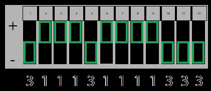

Consulte la Figura A
▪
Interruptor en la posición de ARRIBA (+) = oprima el botón 1 ▪
Interruptor en la posición del MEDIO (0) = oprima el botón 2
Interruptor en la posición de ABAJO (-) = oprima el botón 3
En este ejemplo, el código sería:
Si el abrepuertas tiene un grupo de interruptores con 2 posiciones por interruptor (BINARIO):
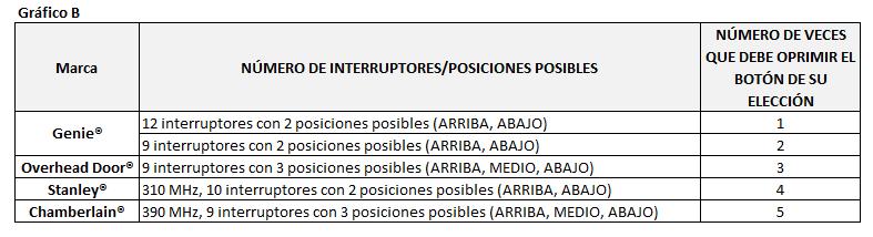
Consulte la Figura A
▪
▪
Interruptor en la posición de ARRIBA (+) = oprima el botón 1
Interruptor en la posición de ABAJO (-) = oprima el botón 3
En este ejemplo, el código sería:
Paso 1: Registre las posiciones de los interruptores
▪
Cada casilla sombreada aquí abajo representa la posición de un interruptor. En estas casillas, anote el número 1, 2, o 3 que corresponda a la posición del interruptor de +, 0, o de – indicada en el control remoto, abrepuertas o receptor. Si tiene menos de 12 interruptores, llene sólo las casillas que tenga. Usted consultará esta sección en el PASO 3.5 abajo.


Paso 2: Determine las especificaciones
▪
▪
Encuentre sus especificaciones del CUADRO B aquí abajo y registre el número aquí:
Esta casilla deberá indicar 1, 2, 3, 4 o 5. Usted consultará esto en el PASO 3.3 abajo.
español 67
Continuación de la página anterior
Paso 3: Programación
1. Retire la lengüeta de activación del interior del compartimiento para pilas
Botones de puerta "DOOR" 1 2 3
2. Mantenga presionado el botón DELAY durante @ 10 segundos hasta que solo se encienda un LED verde en el botón superior, luego suelte. El LED verde seguirá parpadeando.
3. Presione el botón de la PUERTA de su elección el número requerido de veces que corresponda con su abridor de la Tabla B anterior (respuesta registrada del PASO 2).
4. Presione el botón DELAY una vez para indicar que la entrada está completa. El LED verde parpadeará rápidamente para indicar que está listo para recibir las posiciones de interruptor registradas del PASO 1.
5. Ingrese las posiciones del interruptor que determinó en el PASO 1 anterior (una serie de presiones del botón PUERTA: 1, 2 o 3).
6. Después de haber ingresado a la posición final del interruptor, presione y suelte el botón DELAY UNA vez para indicar que la entrada está completa.
7. Pruebe el botón: la siguiente presión del botón PUERTA debería activar el abridor.
FIG A
Botón de demora "DELAY"
68 español
INSTRUCCIONES ALTERNATIVAS
MÉTODO DE PROGRAMACIÓN DE ENSEÑAR Y ENLAZAR (TEACH & PAIR)
Consulte el Cuadro A de las instrucciones principales para encontrar las opciones de programación disponibles.
Para el botón amarillo de aprendizaje ID#4 Chamberlain®/LiftMaster®/Craftsman® - pase inmediatamente a las instrucciones a la derecha. Para todos los otros ID#, continúe con las instrucciones a la izquierda.
para todos los abrepuertas, A EXCEPCIÓN del botón amarillo de aprendizaje ID#4 SÓLO para el Botón amarillo de aprendizaje ID#4 Chamberlain®
1. Retire la lengüeta de activación del interior del compartimiento de pilas
2. Presione y mantenga presionado el botón DELAY hasta que solo se encienda un LED rojo en el botón superior, luego suelte (@ 15 segundos).
3. Coloque el control remoto operativo existente a 1,5 ” - 3” de distancia del frente de la consola de pared inalámbrica universal.
4. Mantenga presionado un botón del control remoto original. No la suelte hasta que la nueva consola de pared inalámbrica universal cambie de parpadeos rojos LENTOS a parpadeos rojos RÁPIDOS. Tendrá 20 segundos para completar.
SUGERENCIA: Si la consola no reconoce la transmisión, intente presionar el botón del control remoto original por períodos de 10 segundos a la vez mientras intenta diferentes distancias entre 1.5 ”-3” de la parte frontal de la consola.Coloque el control remoto existente operacional y la consola mural inalámbrica universal a 5 pies (1.52 m) de distancia entre sí.
5. Cuando la consola de pared cambie a RAPID rojo parpadea, presione el botón DOOR de su elección en la consola UNA VEZ. El LED rojo se volverá fijo y luego se apagará.
6. En el abrepuertas, oprima el botón de aprendizaje/programación, "LEARN/PROGRAM" por 2-3 segundos y luego suéltelo.
7. Oprima el botón de puerta, "DOOR" que acaba de programar una vez cada dos segundos hasta que el abrepuertas funcione.


8. Cuando la puerta deje de moverse, oprima el botón de puerta, "DOOR" nuevamente para hacer una prueba. Se ha completado la programación.
1. Retire la lengüeta de activación
2. Presione y mantenga presionado el botón DELAY hasta que solo se encienda un LED rojo en el botón superior, luego suelte (@ 15 segundos).
3. Coloque el control remoto operativo existente a 1,5”-3” de distancia del frente de la consola de pared inalámbrica universal.
4. Mantenga presionado un botón del control remoto original. No la suelte hasta que la nueva consola de pared inalámbrica universal cambie de parpadeos rojos LENTOS a parpadeos rojos RÁPIDOS. Tendrá 20 segundos para completar.
SUGERENCIA: Si la consola no reconoce la transmisión, intente presionar el botón del control remoto original por períodos de 10 segundos a la vez mientras intenta diferentes distancias entre 1.5 ”-3” de la parte frontal de la consola.Coloque el control remoto existente operacional y la consola mural inalámbrica universal a 5 pies (1.52 m) de distancia entre sí.
5. Cuando la consola de pared cambie a RAPID rojo parpadea, presione el botón DOOR de su elección en la consola UNA VEZ. El LED rojo se volverá fijo y luego se apagará.
6. Ahora, presione y mantenga presionado el botón DOOR que acaba de programar hasta que el LED rojo en el botón superior parpadee y se apague (@ 5 seg.)
7. En el abridor, presione el botón LEARN / PROGRAM durante 2-3 segundos y luego suéltelo.
8. En la consola, presione el botón DOOR que eligió UNA vez. El abridor hará clic.
9. En el abridor, presione el botón LEARN / PROGRAM nuevamente durante 2-3 segundos y luego suéltelo.
10. En la consola, presione el botón DOOR que eligió nuevamente UNA vez. El abridor hará clic de nuevo.
11. Presione el botón DOOR nuevamente y el abridor se activará.
12. Cuando la puerta deje de moverse, presione el botón DOOR nuevamente para probar. La programación está completa.
español 69
Configurar el Wall Mount Según el Tamaño del Tambor
La configuración del tambor de cable está configurado en la fábrica para tambores de 4” de díametro con alzamiento estándar (configuración roja). Sólo hay dos configuraciones para tambores: color rojo o morado. Hay que cambiar la configuración cuando el díametro de tambor es mayor que 4” para puertas con alzamiento estándar y alta elevación (configuración morada) y para puertas con elevación vertical completa (configuración morada). Esa selección es importante para el funcionamiento correcto del abridor.
Cambiar la Configuración para el Tambor
1. Oprima la tecla PRGM/SET hasta que ambas luces LEDs prendan del color AZUL.
2. Oprima la tecla de flecha hacia arriba dos veces.
3. Oprima la tecla PRGM/SET una vez.
4. La configuración muestra la configuración actual: ambas luces LEDs brillan color Rojo.
5. Oprima una vez una tecla ya sea de flecha hacia arriba o hacia abajo. Los LEDs ya brillan color morado.
6. Oprima la tecla PRGM/SET una vez para confirmar el ajuste. Los LEDs brillan azules y se apagan.
7. El abridor ya está listo. Ya se puede programar los límites seguido por los dos ciclos requeridos para calcular la fuerza y el pulso de seguridad que monitorea la tensión del cable.
Genie Tech: Videoteca para Técnicos
70 español
www.geniecompany.com/professional-line-videos
Escanee el código QR con su smartphone. La Contraseña para verlos es: GenieTechVideos ¿Necesita ayuda o tiene alguna pregunta? Llame al teléfono (800) 843-4084 opción 3.


