Isuzu Service Manual S1000 Transmission
This is the cut pages sample. Download all 228 page(s) at:
Full download: http://manualplace.com/download/isuzu-service-manual-s1000-transmission/
ManualPlace.com

Automatic Transmission (S1000 Transmission) .............................
See 2002 Service Manual Diagnosis (S1000 Transmission) ..........................................................7A2-1 Manual Transmission See 1997 Service Manual Clutch See 1997 Service Manual
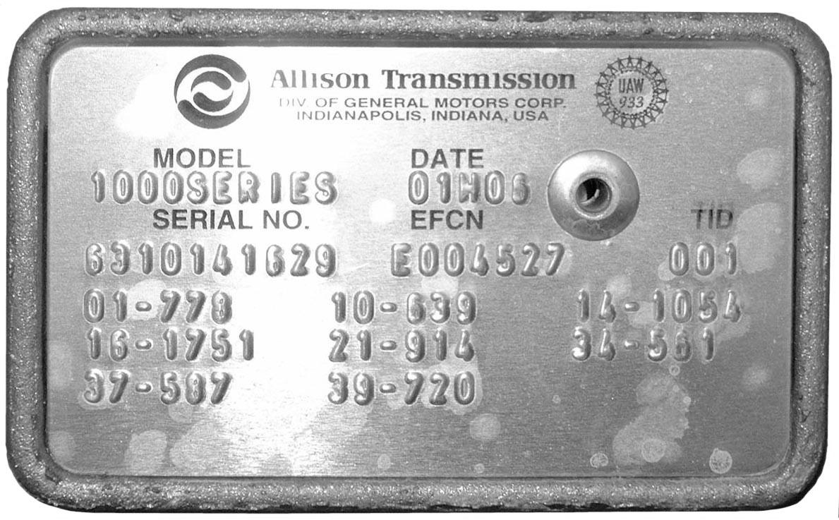
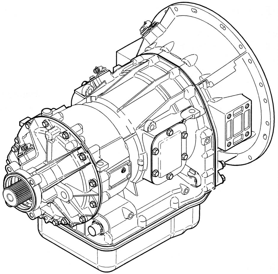
Identification of Transmission .......................................................... 7A2–3
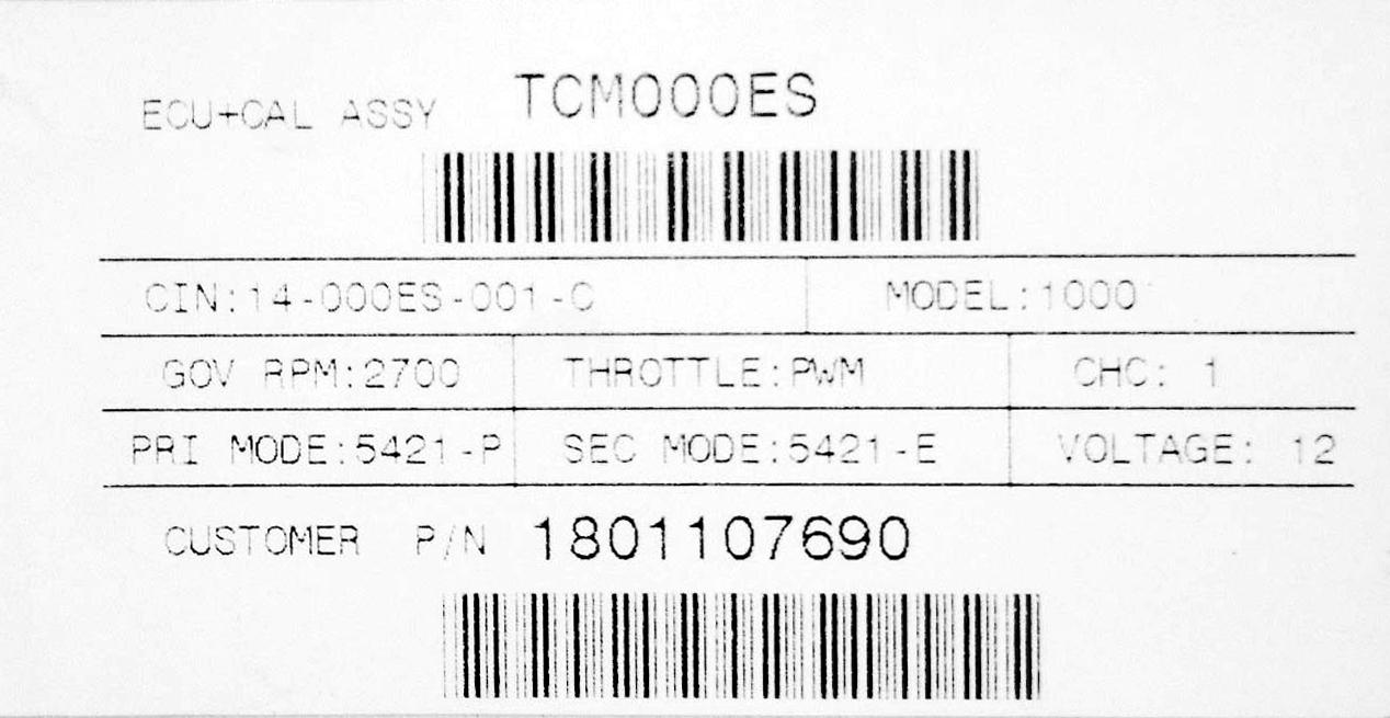
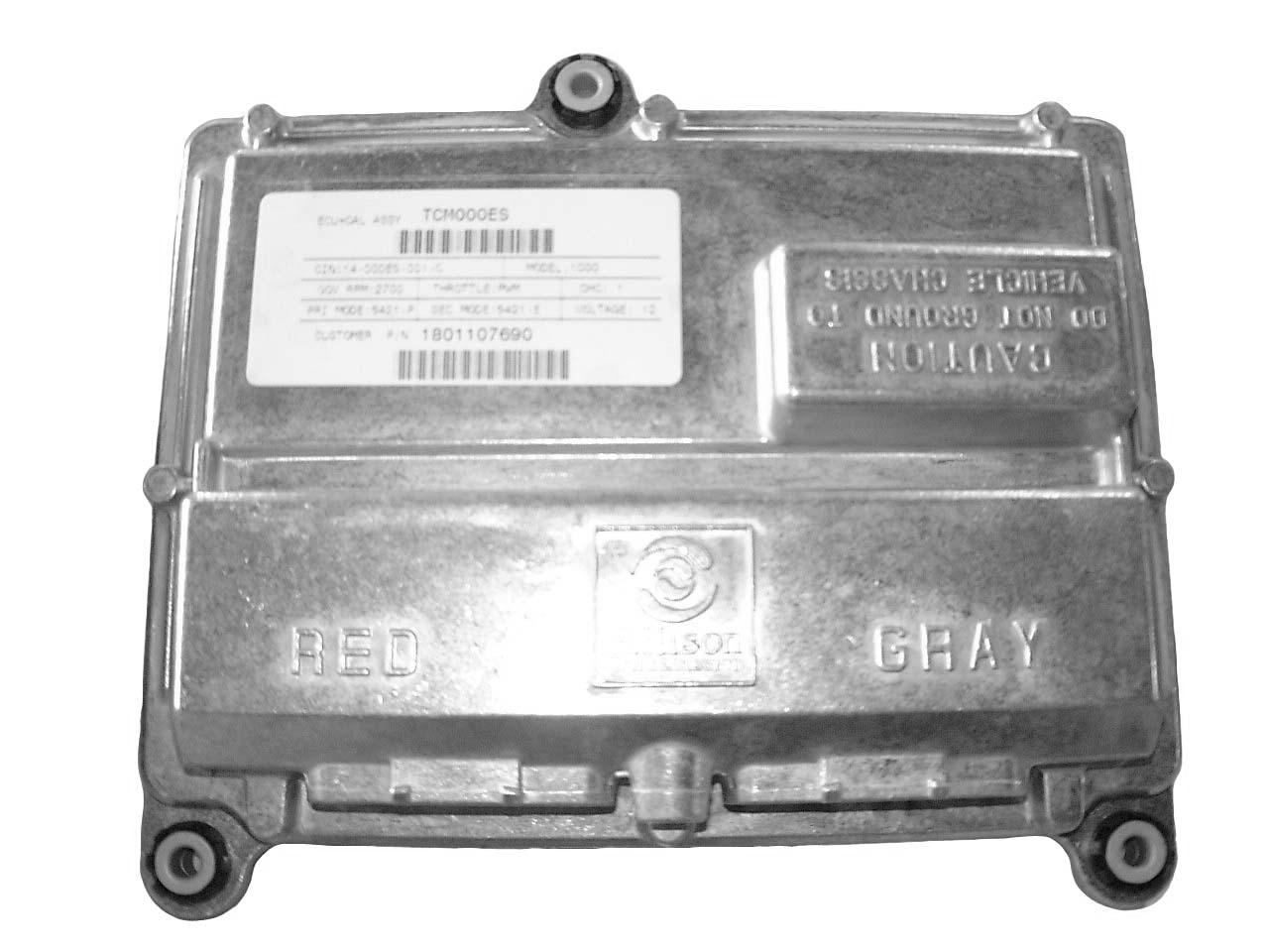
Identification of Transmission Control Module (TCM) ....................................... 7A2–4 System Diagram...................................................................... 7A2–5 Circuit Diagram ...................................................................... 7A2–6
Abbreviations ........................................................................ 7A2–8
Diagnosis by Using Scan Tool 7A2–10
Data Link Connector (DLC) .......................................................... 7A2–10
Verifying Vehicle Repair ............................................................ 7A2–10
Reading Diagnostic Trouble Codes Using a Tech2 of Other Scan Tool ...................... 7A2–10
Clearing Diagnostic Trouble Codes ................................................... 7A2–10
Tech2 Scan Tool 7A2–11
Tech2 Features .................................................................... 7A2–11
Getting Started .................................................................... 7A2–12 Operating Procedure (For example) 7A2–12
Diagnostic Trouble Codes (DTC) ....................................................... 7A2–14
DTC List and Descriptions .......................................................... 7A2–14
DTC P0218 Transmission Fluid Over Temperature Condition .............................. 7A2–16
DTC P0562 System Voltage Low ..................................................... 7A2–19
DTC P0563 System Voltage High ..................................................... 7A2–22
DTC P0602 TCM Not Programmed .................................................... 7A2–25
DTC P0705 Transmission Range Sensor Circuit (PRNDL Input) ............................ 7A2–26
DTC P0706 Transmission Range Sensor Circuit Performance 7A2–29
DTC P0708 Transmission Range Sensor Circuit High Input ............................... 7A2–32
DTC P0711
Transmission Fluid Temperature Sensor Circuit – Performance ................. 7A2–35
DTC P0712 Transmission Fluid Temperature Sensor Circuit – Low Input (High Temperature)...7A2–38
DTC P0713 Transmission Fluid Temperature Sensor Circuit – High Iput (Low Temperature) .... 7A2–41
DTC P0716 Turbine Speed Sensor Circuit Performance .................................. 7A2–44
DTC P0717 Turbine Speed Sensor Circuit No Signal ..................................... 7A2–47
DTC P0721 Output Speed Sensor Circuit Performance ................................... 7A2–50
DTC P0722 Output Speed Sensor Circuit No Signal 7A2–53
DTC P0726 Engine Speed Input Circuit Performance .................................... 7A2–56
DTC P0727 Engine Speed Input Circuit No Signal ....................................... 7A2–59
DTC P0731 Incorrect 1st Gear Ratio ................................................... 7A2–62
DTC P0732 Incorrect 2nd Gear Ratio .................................................. 7A2–65
DTC P0733 Incorrect 3rd Gear Ratio .................................................. 7A2–68
DTC P0734 Incorrect 4th Gear Ratio .................................................. 7A2–71
DTC P0735 Incorrect 5th Gear Ratio .................................................. 7A2–74
DTC P0736 Incorrect Reverse Ratio 7A2–77
DTC P0741 Torque Converter Clutch System Stuck Off .................................. 7A2–80
DTC P0742 Torque Converter Clutch System Stuck On .................................. 7A2–83
DTC P0748 Pressure Control Solenoid A Electrical ...................................... 7A2–86
DTC P0763 Shift Solenoid C Electrical ................................................. 7A2–89
DTD P0768 Shift Solenoid D Electrical ................................................. 7A2–92
DTC P0773 Shift Solenoid E Electrical 7A2–95
DTC P0778 Pressure Control Solenoid B Electrical ...................................... 7A2–98
DTC P0840 Transmission Pressure Switch Solenoid C Circuit ............................ 7A2–101
DTC P0841 Transmission Pressure Switch Solenoid C Circuit Stuck Open ................. 7A2–105
DTC P0842 Transmission Pressure Switch Solenoid C Circuit Stuck Closed ................ 7A2–109
DTC P0843 Transmission Pressure Switch Solenoid C Circuit High ....................... 7A2–113
DTC P0845 Transmission Pressure Switch Solenoid D Circuit ............................ 7A2–117
DTC P0846 Transmission Pressure Switch Solenoid D Circuit Stuck Open ................. 7A2–121
DTC P0847 Transmission Pressure Switch Solenoid D CircuitStuck Closed 7A2–125
DTC P0848 Transmission Pressure Switch Solenoid D Circuit High ....................... 7A2–129
DTC P1709 Transmission Pressure Switch Solenoid E Circuit ............................ 7A2–133
DTC P1710 Transmission Pressure Switch Solenoid E Circuit Stuck Open ................. 7A2–137
DTC P1711 Transmission Pressure Switch Solenoid E Circuit Stuck Closed ................ 7A2–141
DTC P1712 Transmission Pressure Switch Solenoid E Circuit High ....................... 7A2–145
DTC P1713 Transmission Pressure Switch Reverse Circuit .............................. 7A2–149
DTC P1714 Transmission Pressure Switch Reverse Circuit Stuck Open .................... 7A2–153
DTC P1715 Transmission Pressure Switch Reverse Circuit Stuck Closed 7A2–157
DTC P1716 Transmission Pressure Switch Reverse Circuit High .......................... 7A2–161
DTC P1720 Solenoid A Controlled ClutchNot Engaged ................................. 7A2–165
DTC P1721 Solenoid B Controlled ClutchNot Engaged ................................. 7A2–168
DTC P1723 Solenoid A Controlled ClutchEngaged ..................................... 7A2–171
DTC P1724 Solenoid B Controlled ClutchEngaged ..................................... 7A2–174
DTC P1726 Shift Solenoid D Controlled Clutch Engaged ................................ 7A2–177
DTC P1727 Shift Solenoid E Controlled Clutch Engaged ................................ 7A2–180
DTC P1760 TCM Supply Voltabe 7A2–183
DTC P1860 Torque Converter Clutch Pulse Width Modulation (PWM) Solenoid Circuit – Electrical ............................................................ 7A2–186
DTC P1891 Throttle Position Sensor (TPS) Pulse Width Modulation (PWM) Signal Low Input..7A2–189
DTC P1892 Throttle Position Sensor (TPS) Pulse Width Modulation (PWM) Signal HighInput..7A2–191
DTC U1016 Class 2 Powertrain Controller State of Health Failure ......................... 7A2–193
DTC U1300 Serial Data Communication Link Low (Class 2) .............................. 7A2–195
DTC U1301 Serial Data Communication Link High (Class 2) .............................. 7A2–197
DTC Reference Tables 7A2–200
DTC Reference Charts ............................................................. 7A2–201 General Troubleshooting of Performance Complaints..................................... 7A2–207 Appendix (Hydraulic Schematic) 7A2–219
RELAY;EXHCUT(ABS)(5)
A FUSE6(15A)
KEY ON
RELAY; EXHBRAKE(4)
0.85PNK 0.85LTBLURELAY;EXHCUT(ABS)(3) RELAY;EXHCUT(A/T)
FUSE9(15A)
4 3 FU-9 6 FU-18 9 A
H-7 49 CHECKFU-18 TRANS
0.85ORN 0.85VIO
RELAY; IGNITION(1) (GND) FU-35 7
RELAY; IGNITION(1) (KEYON)
0.85LTGRN 0.85BLU/BLK 0.85PNK/BLK 0.85BLKRELAY;EXHCUT(ABS) (1)
0.85LTGRN 0.85PNK/GRN
0.85BLU/YEL
0.85BLU/YEL
8424
0.85PNK/GRN
23
A/TOIL 225 1 FL-250FL-250 4 5 2
RELAY;ABSACTIVE
SWITCH;ECONOMODE
KEY ON FUSE13(15A)
61 H-7 5 FL-9 18
0.85LTGRN/BLK
28
METER 13
FU-35 8 0.850.85YEL/RED YEL/RED 0.850.85LTGRN/BLK LTGRN/BLK 4RELAY;EXHBRAKE(1)
0.85PNK/BLK
10
PTOCONN (FB27-3)(PTOSWITCH)
ALDLCONNECTOR(FL-7)
SWITCH;COMB (EXHAUSTSWITCH)
0.85BLU ECM (E56-20)
H-105 18
H-6 34
0.850.85BLU PNK 7 0.85BLU/WHT 0.850.85BLU/WHT3BLU/WHT BLU S.B.FUSE6(40A)
FL-9 17 0.850.85BRN/BLU BRN/BLU H-10FUSE18(15A) 46 30.85BLU GRN 1 3 4 2
0.85BLK 30.85BLK3BLK BLK
BATTERYEARTH H-1060.85PNK 1
6
FL-93(J1)CONNECTOR(GRAY)TCM(Transmission Control Module)(ALLISON 1000 SERIES TM)
19 RELAY;PTO0.85BRN/RED B+ 31
0.85VIO/GRN 0.5PNK
5
30
H-6 4 29
ECM (E56-1) CONTROLUNIT; SPEEDOMETER (FL11-7)
SHIELD0.5GRY/BLU 0.5BLU 16
32
26 0.5WHT
220 FL-251FL-251 5 D07M200020
155
0.85GRN 0.85GRN/WHT 0.85BLU 0.85BLU/WHT 0.85BRN 0.85BRN/WHT 237
0.85GRN0.85GRN 16662B(Lo) 0.85GRN/WHT0.85GRN/WHT 132371A(Hi) 0.85BLU0.85BLU 142482B(Lo) 0.85BLU/WHT0.85BLU/WHT 172791A(Hi) 0.85BRN0.85BRN 1828102B(Lo) 0.85BRN/WHT0.85BRN/WHT
0.85RED/GRN 0.85RED/YEL 0.85VIO/RED 0.85VIO/GRN 0.85YEL 0.85YEL/VIO
51A(Hi)OUTPUTSPEED SENSOR
J-102 J-95 J-101
0.85RED/GRN 0.85RED/YEL 0.85VIO/RED 0.85VIO/GRN 0.85YEL 0.85YEL/VIO
114M
0.85RED/GRN 2214121L 0.85RED/YEL 2420138N 0.85VIO/RED 25291412P 0.85VIO/GRN 31331514C 0.85YEL 2634166A 0.85YEL/VIO
H-40.85YEL/RED 0.85YEL/GRN 0.85RED/WHT 0.85RED/BLU
J-105 J-103
2737110B
0.85YEL/RED 2838215W 0.85YEL/GRN 2939317J 0.85RED/WHT 3243419S 0.85RED/BLU
0.85YEL/RED 0.85YEL/GRN 0.85RED/WHT 0.85RED/BLU 214453TC D E R
RELAY; NEUTRAL RELAY; IGNITION(2)BACKLAMP
H-10H-120 H-120 H-31
0.85WHT/RED 0.85GRN/WHT 0.85VIO/WHT 0.85BLU/WHT 0.85LTGRN/WHT 1035109G(Hi) 0.85PNK/WHT 20411113H(Lo) 0.85ORN/WHT 0.85PNK/WHT 0.85ORN/WHT 0.85PNK/WHT 0.85ORN/WHT 5481244A 0.85RED/BLU 6401314D 0.85BRN/BLU 0.85RED/BLU 0.85BRN/BLU 0.85RED/BLU 0.85BRN/BLU 7471424B 0.85LTGRN/BLU 8541534C 0.5RED 1.25PNK 133 4467F 1.25RED
TURBINESPEED SENSOR ENGINESPEED SENSOR SOLA(PCS) SOLB(PCS) SOLCON/OFF SOLDON/OFF PRESSURESWITCH MANIFOLD MAINTRANSMISSION CONNECTOR
0.85ORN/WHTJ-104 FUSE9(15A)
SUMPTEMP SENSOR
B C 0.85P PNK/BLU 0.85LTGRN/BLU 0.85PNK/BLU 0.85LTGRN/BLU 0.85PNK/BLU 0.5BLU 0.5RED 1.25PNK 1.25RED
NOTE;CONNECTORNo.
WIRESIZE(mm2) WIRECOLOR
H-10 5 0.85GRN
FEMALESIDE CONNECTORTERMINALNo. MALESIDECONNECTOR
SOLEON/OFF SOLF(PWM)LOCKUP NSBUSWITCH ONTRANSMISSION D07M200002
A/N
Assembly Number
ABS Anti-lock Brake System
AmpUnit of electrical current.
CAN Controller Area Network – A network for all SAE J1939 communications in a vehicle (engine, transmission, diagnostics, ABS, etc.)
CT Closed Throttle
DNA Does Not Adapt – Adaptive shift control is disabled.
DNS DO NOT SHIFT – Refers to the DO NOT SHIFT diagnostic response during which the CHECK TRANS light is illuminated and the transmission will not shift and will not respond to the Shift Selector.
DTC Diagnostic Trouble Code
DVOM Digital volt/ohmmeter
ECM Engine Control Module – Available on electronically-controlled engines – provides some relevant data to TCM.
GPI General Purpose Input – Input signal to the TCM to request a special operating mode or condition.
GPO General Purpose Output – Output signal from the TCM to control vehicle components (such as PTOs, backup lights, etc.) or allow a special operating mode or condition.
J1939High-speed vehicle serial data communications link.
LED Light-Emitting Diode – Electronic device used for illumination.
NNC Neutral No Clutches – Neutral commanded with no clutches applied.
NSBU Switch Neutral Start Backup Switch
NVL Neutral Very Low – The TCM has sensed turbine speed below 150 rpm. This is usually caused by a dragging C1 or C3 clutch or a failed turbine speed sensor. When attained, the C4 and C5 clutches are applied to lock the transmission output.
OBD II On Board Diagnostics Second generation. EPA mandated specification for vehicle diagnostics.
OhmUnit of electrical resistance.
PCCS Production Calibration Configuration System
PPC Pressure Proportional to Current solenoid. Solenoid control of clutch pressure is proportional to the current being supplied to the solenoid.
PROM Programmable Read Only Memory
PSM Pressure Switch Module – Part of transmission control system located inside the oil pan.
PTO Power Takeoff
PWM Solenoid Pulse Width Modulated Solenoid – Solenoids are controlled by pulse width modulation. Solenoid control of clutch pressures is based on the solenoid’s duty cycle. Duty cycle is determined by the ratio of solenoid’s on-time to off-time.
RPR Return to Previous Range – Diagnostic response is which the transmission is commanded to return to previously commanded range.
TCM Transmission Control Module (also commonly referred to at the “computer”)
TFT Transmission Fluid Temperatrure – Data provided by thermistor that is part of the PSM.
TID TransID – A feature which allows the TCM to know the transmission configuration and provide the corresponding calibration required.
TPS Throttle Position Sensor – Potentiometer for signaling the position of the engine fuel control lever.
V Version – Abbreviation used in describing TCM software levels.
VDC Volts Direct Current (DC)
VIW Vehicle Interface Wiring – Interfaces TCM programmed input and output functions with the vehicle wiring.
VoltUnit of electrical force.
VOM Volt/ohmmeter
WOT Wide Open Throttle
∞
Infinity – Condition of a circuit with higher resistance than can be measured, effectively an open circuit.
The provision for communication with the control module is the Data Link Connector (DLC). It is located at the lower left of the instrument panel behind a small square cover.
Verification of vehicle repair will be more comprehensive for vehicles with OBD system diagnostic. Following a repair, the technician should perform the following steps:
1.Review and record the Fail Records for the DTC which has been diagnosed.
2.Clear DTC(s).
3.Operate the vehicle within conditions noted in the Fail Records.
4.Monitor the DTC status information for the specific DTC which has been diagnosed until the diagnostic test associated with that DTC runs. Following these steps are very important in verifying repairs on OBD systems. Failure to follow these steps could result in unnecessary repairs.
The procedure for reading diagnostic trouble code(s) is to used a diagnostic scan tool. When reading DTC(s), follow instructions supplied by tool manufacturer.
The DLC is used to connect to a scan tool. Some common uses of the scan tool are listed below:
• Identifying stored Diagnostic Trouble Codes (DTCs).
• Clearing DTCs.
• Performing output control tests.
• Reading serial data.
IMPORTANT: Do not clear DTCs unless directed to do so by the service information provided for each diagnostic procedure. When DTCs are cleared, the Failure Record data which may help diagnose an intermittent fault will also be erased from memory. To clear Diagnostic Trouble Codes (DTCs), use the diagnostic scan tool “clear DTC information” function. When clearing DTCs follow instructions supplied by the tool manufacturer.
When a scan tool is not available, DTCs can also be cleared by connect the memory clear switch (Blue) one to two second then disconnect the memory clear switch (Blue).
From 98 MY, Isuzu Dealer service departments are
recommended to use Tech 2. Refer to Tech 2 scan tool user guide. 1 2 3 4
Legend (1)PCMCIA Card (2)Tech-2
1Tech 2 is a 12 volt system. Do not apply 24 volt.
2.After connecting and/or installing, the Vehicle Communications Interface (VCI) module, PCMCIA card and DLC connector to the Tech 2, connect the tool to the vehicle DLC.
3.Make sure the Tech 2 is powered OFF when removing or installing the PCMCIA card.
4.The PCMCIA card has a capacity of 10 Megabytes which is 10 times greater than the memory of the Tech 1 Mass Storage Cartridge.
5.The Tech 2 has the capability of two snapshots.
6.The PCMCIA card is sensitive to magnetism and static electricity, so care should be taken in the handling of the card.
(3)DLC Cable (4)SAE 16/19 Adapter
7.The Tech 2 can plot a graph when replaying a snapshot.
8.Always return to the Main Menu by pressing the EXIT key several times before shutting down.
9.To clear Diagnostic Trouble Codes (DTCs), open Application Menu and press “F1: Clear DTC Info”.
• The following table shows, which functions are used the available equipment versions.
On OBD has two options available in the Tech 2 DTC mode to display the enhanced information available. A description of the new modes, DTC Info and Clear DTC Information. After selecting DTC, the following menu appears:
• DTC Info
• Clear DTC Information
To clear Diagnostic Trouble Codes (DTCs), use the diagnostic scan tool “clear DTC information” function.
Use the Tech 2 Data Values only after the On-Board Diagnostic System Check has been completed, no DTC(s) were noted, and you have determined that the on-board diagnostics are functioning properly. Tech 2 values from a properly-running engine may be used for comparison with the engine you are diagnosing. The Tech 2 data values represent values that would be seen on a normally-running engine.
• Before operating the Isuzu PCMCIA card with the Tech 2, the following steps must be performed:
1.The Isuzu 98 System PCMCIA card (1) inserts into the Tech 2 (2).
2.Connect the SAE 16/19 adapter (4) to the DLC cable (3).
3.Connect the DLC cable to the Tech 2 (2).
4.Make sure the vehicle starter key is off.
6.The
vehicle starter switch turns on.
The power up screen is displayed when you power up the tester with the Isuzu systems PCMCIA card. Follow the operating procedure below.
Full download: http://manualplace.com/download/isuzu-service-manual-s1000-transmission/
This is the cut pages sample. Download all 228 page(s) at: ManualPlace.com