FUNDAMENTALS OF STRUCTURAL ANALYSIS
5th Edition
SOLUTIONS MANUAL
CHAPTER 5: BEAMS AND FRAMES
5-1
Copyright © 2018 McGraw-Hill Education. All rights reserved.
without the prior written consent of McGraw-Hill Education.
No reproduction or distribution
Kenneth M. Leet, Chia-Ming Uang, Joel T. Lanning, and Anne M. Gilbert
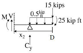
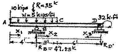
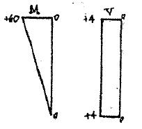
P5.1. Write the equations for shear and moment between points B and C as a function of distance x along the longitudinal axis of the beam in Figure P5.1 for (a) origin of x at point A, and (b)
origin of x at D
ΣMA =-10(8)-25(0.5 10)-25+20C y = 0
C y = 34 kips
ΣF y = A y -8-0 5 10-15+34 = 0
A y =-6 kips
a) Cut beam with origin at A
ΣF y =-6-8-V = 0
V =-14 kips
ΣMA =-M +(10)⋅8+ x(-14)= 0
M =80-14x kip⋅ft
b) Cut beam with origin at D
ΣF y =-0.5(10)-15+V +34= 0
V =-14 kips
ΣMD = M +(x2 )⋅(-14)+10(34)-0.5(10)(5)+25 = 0
M =14x -340 kip⋅ft
5-2
Copyright © 2018 McGraw-Hill Education. All rights reserved. No reproduction or distribution without the prior written consent of McGraw-Hill Education.
8
15
w = 0.5
25
•
kips
kips
kip/ft
kip
ft
A B C D 10ʹ 10ʹ 10ʹ P5 1
Write the equations for shear and moment
No reproduction or distribution
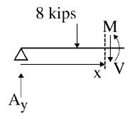
A x ç ÷ x P5.2.
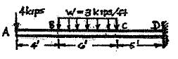
6ʹ B 8 kips w = 3 kips/ft C A E D 5ʹ 3ʹ x 10ʹ P5.2 ΣMA
E y = 0 E y
19 kips ΣF y
A y
E y = 0 A y =11 kips ΣF x = E x -8= 0 8 kips B C D 3 kips/ft E x =8 kips Ay Ey ΣF y = V x -3(10- x
V x
3x +11 kips ΣM = M + æ xö ÷ 3x -19(x) = 0 è2ø 3 kips/ft Vx Mx M =19x3 x 2 kip⋅ft 2 D x 10-x Ey
Copyright © 2018 McGraw-Hill Education. All rights reserved.
without the prior written consent of McGraw-Hill Education.
=-6(8)+13(3 10)-18
=
=
-3 10+
)+19
=
Copyright © 2018 McGraw-Hill Education. All rights reserved.
No reproduction or
5-3
distribution without the prior written consent of McGraw-Hill Education.
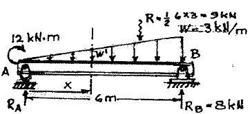
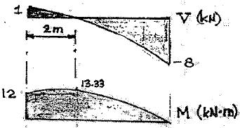
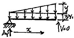
P5.3. Write the equations for shear and moment between points A and B Select the origin at A. Plot the graph of each force under a sketch of the beam The rocker at A is equivalent to a roller
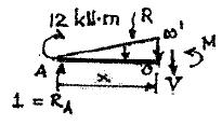
Check@ x = 6: M =12+6-36(6) 12 M =18-18= 0
Copyright © 2018 McGraw-Hill Education. All rights reserved.
or distribution without the prior written consent of McGraw-Hill Education.
No reproduction
MA = 12 kN • m A 6 m P5.3 w 3 kN/m B + V and M Diagrams ΣM = 0; 12kN m + R 6 m-(9kN)2 m = 0 B A R = 6 -1 kN A 6 1 æ xö ÷ x 2 R = ´ = 2 ç è2÷ ø 4 W ¢ = 3 \ W ¢ = x x 6 2 kN 1 + ΣF y = 0; 1´W ¢-V = 0 2 V =11 æ x ö ÷ ´ ç ÷ 2 è2ø x 2 V =1- Ans. 4 + x 2 æ x ö ÷ ΣMO = 0; 1(x)+12ç ÷ - M = 0 4 è3ø M =12+ x - R æ xö ÷ ç è3÷ ø x 3 M =12+ x - Ans. 12
5-4
P5.4. Write the equations for shear V and moment M between points B and C Take the origin at point A. Evaluate V and M at point C using the equations.
Copyright © 2018 McGraw-Hill Education. All rights reserved.
without the prior written consent of McGraw-Hill Education.
5-5
No reproduction or distribution
z ç ÷
= 5 kips/ft C D A B 4ʹ 9ʹ 4ʹ P = 10 kips P5.4 For 4 ft < x < 13 ft A 4 ft 5 kips/ft B 10 kips x z V(x) M(x) ΣF y = 0 =-V(x)+10-5x V(x) =-5
V(13) = VC =
ΣM = 0 =-M
æ x
è2ø
2
w
x +10 kips
-55 kips
(x)-5x
ö ÷+10(x -4)
M(x) =5 x 2 +10(x -4)-40 kip ft
M(13) = MC =-332.5 kip ft
P5.5. Write the equations for moment between points B and C as a function of distance x along the longitudinal axis of the beam in Figure P5.5 for (a) origin of x at A and (b) origin of x at B
5-6
Copyright © 2018 McGraw-Hill Education. All rights reserved.
without the prior written consent of McGraw-Hill Education.
No reproduction or distribution
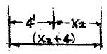
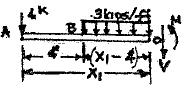
Freebody Segment Origin Range V Equation M Equation Diagram BC A 4¢ £ x1 £10¢ + + ΣF y = 0; ΣMO = 0; k k /1 -4x1 - M1 -3(x1 -4 ) V =8-3x (x1 -4¢) 2 M =3(x -4¢)2 -4x1 BC B 0 £ x2 £6¢ + = 0;k + ¢ -æ x2 ö ÷ = ç è 2 ÷ ø 0 M =-16-4x3 x 2 2 2 2 2 + ΣFY = 0; k V =-4-3x 2 2 1 1 2 2 M
4 kips A 4ʹ w = 3 kips/ft B C D 6ʹ 5ʹ P5 5 -4 -V -3 (x -4¢) = 0 1 1 = 0 1 2 1 -4 -V -3x = 0 ΣMO 4 (x2 4 ) 2 3x2
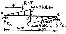
P5.6. Write the equations required to express the Figure P5 6 Use an origin at point A, and then repeat computations using an origin at point D Verify that both procedures give the same value of
Copyright © 2018 McGraw-Hill Education. All rights reserved.
without the prior written consent of McGraw-Hill Education.
5-7
No reproduction
4 4 2 2 6 6 6 2 6 3 3 4 4 2 1 x
or distribution
moment
C 18 kips A 6ʹ C D 10ʹ 8ʹ P5.6 Origin at “A” é x ù Origin at “D” A-B M = 39.1x -2.4x ê 1 ú C-D M =17.3x 1 1 1 ê ú ë û (x -8) 2 B-C M =17.3x -(x -8)2.4 5 = 39.1x1 -1.2x1 5 5 5 2 é x ù =17.3x -1.2(x -8)2 B-C M = 39.1x -2.4x ê 2 ú-18(x -6) 5 5 2 2 2 ê ú 2 ë û B-A M =17.3k x -18k ( x -18) = 21.1+ x2 -1.2x2 +108 C-D M3 =39.1x3 -18(x3 -6)-2.4´16(8+ x3 -16) -2.4(x -8) (x6 -8) 2 M = 415.2-17.3x M = -1.2(x -8)2 -0.7x +324 6 6 6 Check Moment at “C” M =17.3x =17.3´8¢ =138.4 kip ft 2 18kips B 2.4kips/ft M = 21.1´16-1.2(16) +108=138.4 K G A C M1 M2 M3 x Ay = 39 1kips 2 x3 By = 17.3kips 18kips B 2 4 kips/ft A C
at point
Copyright © 2018 McGraw-Hill Education. All rights reserved.
5-8
No reproduction or distribution without the prior written consent of
Education. x x5 x M6 M5 M4 4 By = 17 3 kips A y = 39 1 kips 6
McGraw-Hill
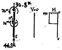
P5.7. Write the equations for shear and moment the shear and moment at C, using the equations
Copyright © 2018 McGraw-Hill Education. All rights reserved.
without the prior written consent of McGraw-Hill Education.
5-9
No reproduction or distribution
2 3
10 kips C
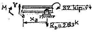
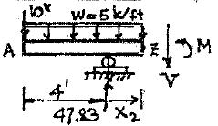
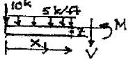
. A B 32 kip ft D x x x 4ʹ 3ʹ 6ʹ P5.7 + ΣMD = 0 =-10´13-35´9.5+32+9RB RB = 47.83kips + ΣF = 0 = 47.83-10-35- R ; R = 2.83k y D D Segment AB: + 0 £ x1 £4 ΣE y = 0 =-10-5x1 -V \ V =-10-5x1 + ΣM x = 0 =10x +5x x1 + M 1 1 2 M =-10x5 x 2 1 2 1 Segment BC: + 0 £ x2 £3 ΣF y = 0 =-10-(4+ x2 )5+47.83-V V =-30-5x2 + 47.83 V =17 83-5x2 + æ + ö2 ΣM = 0 =-M -10(4+ x )-5ç 4 x2 ÷ +47.83x Z 2 ÷ ø 2 M =-40+37.83x5(4+ x )2 2 2 2 Segment DC: + 0 £ x3 £6¢ ΣF = 0; V -2.83k = 0; V = 2.83k y C C + ft k Σ MZ = 0; M +32 +2 83x3 = 0 M =-32ft k -2.83x MC (x3 -6¢)=-49 ft k
based on the origin at point D
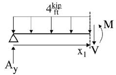
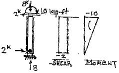
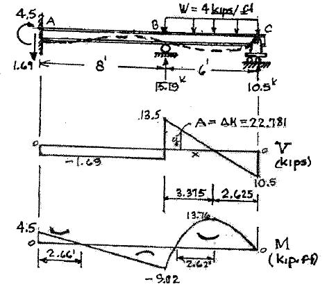
P5.8. Write the equations for shear V and moment M in terms of distance x along the length of the beam in Figure P5.8. Take the origin at point A.
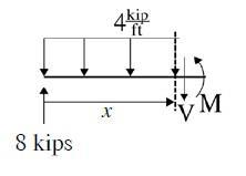
ΣF y =-V +8-4x = 0
Copyright © 2018 McGraw-Hill Education. All rights reserved.
reproduction or
without the prior written consent of McGraw-Hill Education.
5-10
B C
No
distribution
ΣM =-M -ç ÷ 4x + x(8) = 0
w = 4 kips/ft A 15 kips 8 kips 10ʹ 6ʹ P5.8
V
æ
ç è2÷
=8-4x kip
x ö ÷
ø M =8x -2x 2 kip ft
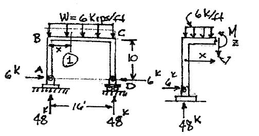
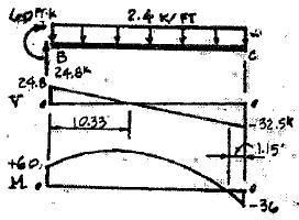
P5.9. Write the equation for moment between points B and C for the rigid frame in Figure
Copyright © 2018 McGraw-Hill Education. All rights reserved.
without the prior written consent of McGraw-Hill Education.
5-11
No reproduction
distribution
ΣMZ = 0 = 48x -6´10-6xç ÷ - M
or
P5.9. w = 6 kips/ft B C 10ʹ 6 kips A D 6 kips 48 kips 16ʹ 48 kips P5.9 Member BC 0 £ x £16¢ Section (1) + æ x ö ÷ ç è2ø ÷ M =-60+48x -3x 2
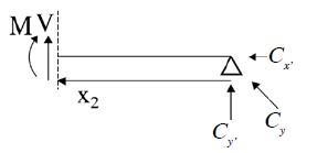
P5.10. Write the equations for moment as a function of distance along the longitudinal axes for members AB and BC of the frame in Figure P5 10. Origins for each member are
ΣM = æ7ö÷(4)7+7(60)-8-12C = 0

è2ø
C y = 42.5 kips
ΣF y = A y -4(7)-60+42.5 = 0
A y = 45.5 kips
ΣF x = A x +12= 0
A x =12 kips
Cut of segment AB
ΣF y = 45.5-4x -V = 0
V = 45.5-4x kips æ x ö ÷
ΣM = M + ç è2÷ ø ⋅4x - x(45 5) = 0
M x = 45 5x -2x kip⋅ft
Cut segment CB æ 169ö ÷
C =ç ÷ C = 46.04 kips
y¢ ç ÷ y 12
ΣF y = V +46.04 = 0
V =-46.04 kips
ΣMC = M x - x(46.04) = 0
M x = 46.04x kip ft
5-12
Copyright © 2018 McGraw-Hill Education. All rights reserved. No reproduction or distribution without the prior written consent of McGraw-Hill Education.
A ç ÷ y
2
w 4 kips/ft A x 60 kips B 12 kips
6ʹ 1 8 kip ft x2 6ʹ C 7ʹ 5ʹ P5.10
shown.
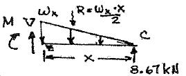
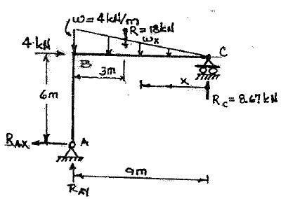
P5.11. Write the equations for shear and moment between points B and C for the rigid frame in Figure P5 11. Select the origin at point C
Reactions
ΣF x = 0; +
RAX = 4 kN ¬
ΣM = 0; 4kN ´6+18kN ´3- R 9 = 0 RC =8.67 kN
ΣF y = 0;
W x = 4 ;
RAY -18+8.67 = 0 RAY = 9.33 kN
W = 4 x x 9 9
5-13
Copyright © 2018 McGraw-Hill Education. All rights reserved.
without the prior written consent of McGraw-Hill Education.
No reproduction
A C 2
+
or distribution
k
4 kN w = 4 kN/m B C x 6 m A 9 m P5.11
+
Shear Σ
V
W
2 V = 4 x ⋅ x -8.67 9 2 V = 2 x 2 -8.67 9 Moment + ΣMZ = 0; M +W x æ xö ÷-8.67x = 0 ç ÷ x 2ç è3÷ ø M 8.67x æ4 x ÷ ö x = -ç ÷ ç è9 6 3 M =8.67x2x 27
F y = 0;
=
x x +8.67 = 0
P5.12. Consider the beam shown in Figure P5.12.
(
a) Write the equations for shear and moment using an origin at end A.
(
b) Using the equations, evaluate the moment at section 1.
(
c) Locate the point of zero shear between B and C.
(
d) Evaluate the maximum moment between points B and C.
(
e) Write the equations for shear and moment using an origin at C.
(
f ) Evaluate the moment at section 1
(
g) Locate the section of maximum moment and evaluate M max .
(
h) Write the equations for shear and moment between B and C using an origin at B
(
) Evaluate the moment at section 1
z
Copyright © 2018 McGraw-Hill Education. All rights reserved.
without the prior written consent of McGraw-Hill Education.
5-14
No reproduction or distribution
w = 3 kips/ft ips 3 kips/ft 4’ 5’ max 1 max
i
P = 8 kips 1 A B 5ʹ 4ʹ P5 12 C 16ʹ 1 + ΣMB = 0; 8´4-48´8+14RC = 0 8 k ΣF y = 0; RC = 22 kips -8-48+ RB +22 = 0 A C 16’ RB =34 kips (a) A–B Origin at “A;” 0 £ x £ 4 By = 34 kips 8 kips 8 kips Cy = 22 kips 3(x – 4) M(x) + ΣF y = 0; ΣM z = 0; -8-V = 0 V =-8k M +8x = 0 V(x) x z M(x) A 4’ x – 4 B y = 34kips x z V(x) + M =-8x N k + (c) Locate Point V = 0 B -C ΣF y = 0; -8+34-3(x -4)-V = 0 V =-3x +38 (EQ. 1) UseEQ 1 0 =-3x +38 x =12.67 + ΣM 0; 8x 34(x 4) 3(x 4) (x -4) M 0 = - - + - + = 2 M =-1.5x 2 +38x -160 (EQ 2) (d) M max : Set x =12.67in (EQ 2) 2 M =-1.5(12.67) +38´12.67-160 (b) Moment at (1) set x = 9 2 =-240.79+481.46-160 M =-1.5(9) +38 9-160 M = 80.67 kip⋅ft
=-121.5+340-160
= 60.5 kip ft
5-15
Copyright © 2018 McGraw-Hill Education. All rights reserved.
without the prior written consent of McGraw-Hill Education.
No reproduction
distribution
or
Copyright © 2018 McGraw-Hill Education. All rights reserved.
5-16
No
M M
(
+ ΣF
+ ΣM
0; V
0 V
3
M +3
x
0 2 M = 22
1 x 2 2 M(x) z V(x) 3x x Cy = 22 kips A–
+ ΣF
0; + Σ
0; -8
0 V =-8k -8(20-
M
0 M
8 kips A 20– x V(x) z M(x)
f
M
A
2
2
ft 2
g
M max
V
0; V
7.332 3 -22+3x = 0 max max +
3
2 2
h
0; + -8+34-3
0 V
8 kips 3x ΣM 0; 8(4 K) 34x 3x x M 0 = -
= 2
3 x 2 A 2 4’ M(x) z x
÷ 2
5 By = 34 kips x V(x)
reproduction or distribution without the prior written consent of McGraw-Hill Education.
z P5.12. Continued
e) B–C
y = 0;
z =
-3x +22=
=-22+
x
x x -22
=
x
B
y =
MZ =
k -V =
x)-
=
=8x -160
(
)
at section (1) R
+ x =11
M = 22(11)3 (11)
= 60.5 kip
(
)
, Set
=
= 22 =
= 22´7.33-
(7.33)
=161.26-80.59 = 80.67 kip⋅ft (
) ΣF y =
x -V =
= 26-3x
+ + - -
M =-32+26x -
(i) Moment at section (1) Let x = 5¢ æ3ö
M =-32+26(5)-çè2÷ ø
M = 60.5 kip ft
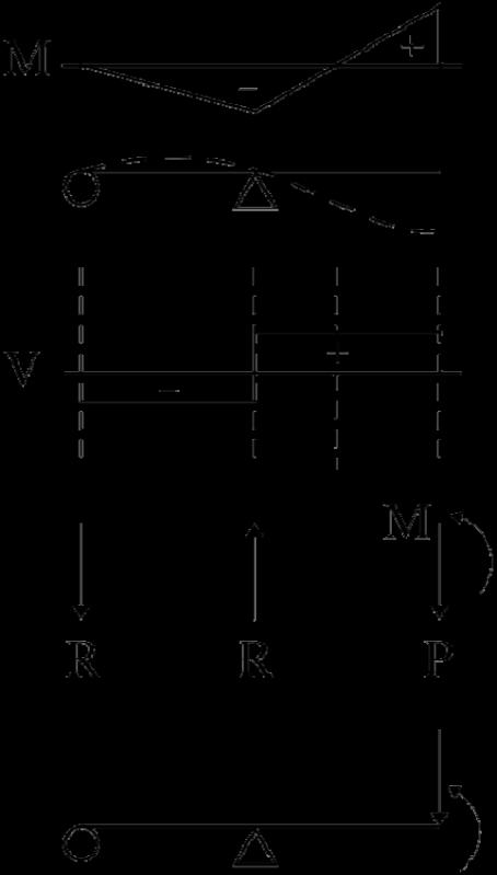
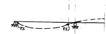
P5.13. For each beam, with given moment A B C diagram: (a) sketch the deflected shape; and (b) determine, qualitatively, the applied loading.
Constant negative shear results in a linear moment diagram with negative slope. Likewise, constant positive shear results in a linear moment diagram with positive slope. Constant shear occurs when no distributed load is present. A jump in moment diagram arises from an applied concentrated moment.
5-17
Copyright © 2018 McGraw-Hill Education. All rights reserved.
without the prior written consent of McGraw-Hill Education.
No reproduction
or distribution
moment P5 13
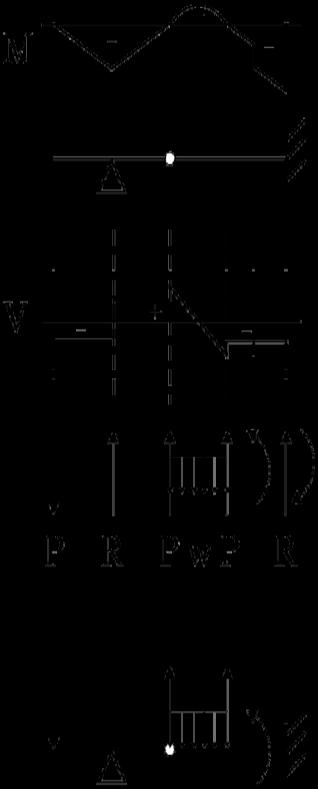
P5.14. For each beam, with given moment diagram: (a) sketch the deflected shape; and (b) determine, qualitatively, the applied loading. moment
5-18
Copyright © 2018 McGraw-Hill Education. All rights reserved.
without the prior written consent of McGraw-Hill Education.
No reproduction
or distribution
A B C D
P5.14
P5.15. For each beam, draw the shear and moment curves label the maximum values of
shear and moment, locate points of inflection,
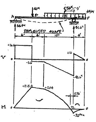
and sketch the deflected shape.
Copyright © 2018 McGraw-Hill Education. All rights reserved.
without the prior written consent of McGraw-Hill Education.
5-19
No reproduction
or distribution
40 kips w = 4 kips/ft
A D
C 6ʹ 4ʹ 10ʹ 4ʹ P5.15
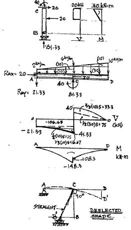
P5.16. For each beam, draw the shear and moment diagrams, label the maximum values of shear and moment, locate points of inflection,
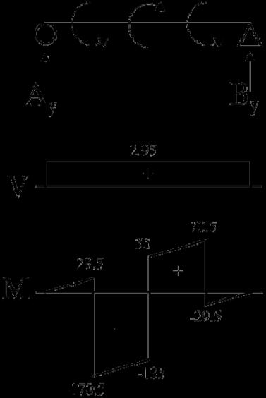
and sketch the deflected shape
ΣMA =-200+170-100-44B y = 0
B y =-2.95 kips
ΣF y = A y -2.95= 0 A y = 2.95 kips
Deflect
kip • ft 170 kip • ft 100 kip • ft
5-20
Copyright © 2018 McGraw-Hill Education. All rights reserved. No
or distribution without the prior written consent of McGraw-Hill Education.
reproduction
200
A B C
10ʹ 12ʹ 12ʹ 10ʹ P5.16
D E
A
y By Shear Moment
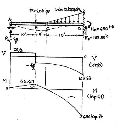
P5.17. For each beam, draw the shear and moment curves label the maximum values of shear and moment, locate points of inflection, and sketch the deflected shape.
Copyright © 2018 McGraw-Hill Education. All rights reserved.
without the prior written consent of McGraw-Hill Education.
5-21
No reproduction
distribution
or
P 20 kips A B hinge C w 12 kips/ft D 10ʹ 5ʹ 15ʹ P5 17
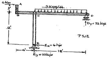
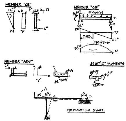
P5.18. For each beam, draw the shear and
kips 12 kips moment curves label the maximum values of shear and moment, locate points of inflection,
and sketch the deflected shape.
FBD of segment CDE
ΣMC = 0 = 3(5)-195+12(15)- D y
(10)
D y = 0 kips
ΣF y = 0 =-VC -3-12
VC =-15 kips
FBD of segment ABC
ΣMA = 0 =-B y (25)+15(30)
B y =18 kips
ΣF y = 0 =-15+18+ A y
VC =-3 kips
Copyright © 2018 McGraw-Hill Education. All rights reserved.
5-22
No reproduction or distribution without
prior
consent
Education. VC = 15 kips C 25ft 5 ft -3 kips B = 18kips 15 15 -3 75 7-5 POI
the
written
of McGraw-Hill
3
A
C 195 kip ft B D E hinge 25ʹ 5ʹ 5ʹ 5ʹ 5ʹ P5.18
VC 3 kips C 195kips 12kips D E Dy
Ay = y 5 ft 5 ft 5 ft
Shear (kips)
POI
Moment (kip-ft) Deflected Shape
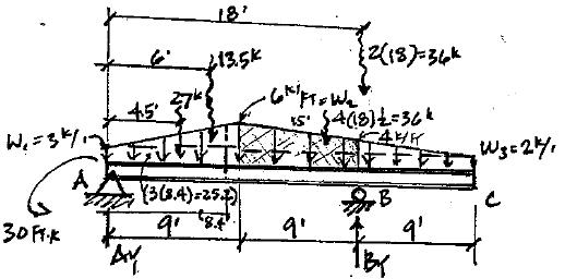
moment curves label the maximum values of shear and moment locate points of inflection, and sketch the deflected shape.
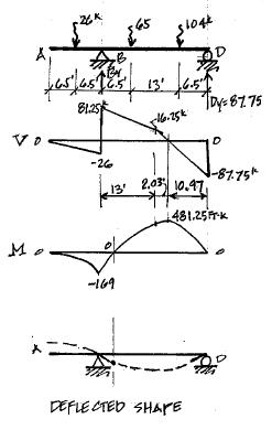
w1 = 2 kips/ft
w2 = 5 kips/ft
B = 0; -26(6.5¢)+65(6.5¢)+104(19.5¢)- D y (26¢)= 0
D =87.5k + ΣF = 0; -26k + B -65k -104k - D = 0 y y y
B =107.25k
y y
Copyright © 2018 McGraw-Hill Education. All rights reserved.
or
without the prior written consent of McGraw-Hill Education.
5-23
No reproduction
distribution
A B C D 13ʹ
13ʹ
+ Σ
13ʹ
P5 19
M
P5.20. For each beam, draw the shear and moment curves label the maximum values of shear and moment locate points of inflection, and sketch the deflected shape.
Copyright © 2018 McGraw-Hill Education. All rights reserved.

5-24
No reproduction or distribution
A k /1 2 2 2 = A = @A y y
without the prior written consent of McGraw-Hill Education.
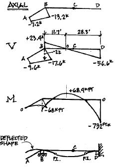
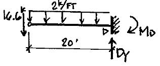
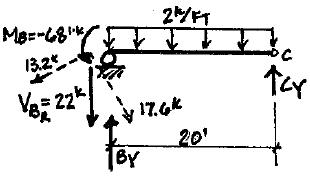
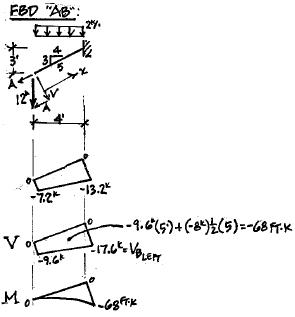
3ʹ w = 2 kips/ft B C D A P = 12 kips rocker support hinge 4ʹ 20ʹ 20ʹ P5 20 Shear @ A: Entire Structure: 12k 5¢ VA 4¢ V = 9.6k @B x = 5¢ 2k /1(5¢) 5¢ = VBW 4¢ VBW =8k \ VB = 9.6k +8k =17.6k Axial Force @ A: 12k 5¢ AA 3¢ = 7.2k @B, x 5¢: 2 (5¢) k (3¢) 6 = = 5 \ A = 7.2k +6k =13.2k FBD “BC” + ΣM = 0; -68ft k -22k (20¢)-2k /1 (20) + B (20¢)= 0 C y B = 45 4k + ΣF = 0; -22k -2k /1(20¢)+45.4k +C = 0 y y C =16.6k FBD “CD” + ΣF = 0; -16.6k -2(20¢)+ D = 0 D = 56.6k y y y + ΣM = 0; -2 k /1(20) 2 -16 6 k (20¢)+ M = 0 M = 732ft k D D D
P5.21. For each beam, draw the shear and moment curves label the maximum values of shear and moment, locate points of inflection, and sketch the deflected shape.
Copyright © 2018 McGraw-Hill Education. All rights reserved.
without the prior written consent of McGraw-Hill Education.
5-25
No reproduction or distribution
B 2 y y y
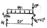
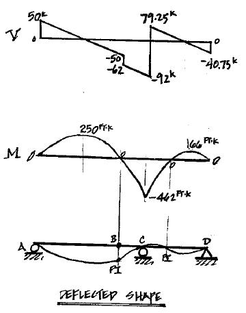
P = 12 kips w = 5 kips/ft A hinge B C D 20ʹ 6ʹ 24ʹ P5.21 FBD “AB” + ΣM = 0; 5k /1(20¢)2 +12k (20¢)-V (20¢) = 0 A B 2 2 V = 62k 2 + ΣF = 0; A -F k /1(20¢)+62k -12k = 0 y y A = 50k FBD “BCD” + ΣM = 0; 5k /1(30¢)2 -62k (30¢)- + C (24¢)= 0 D y C =171.25k + ΣF = 0; -62k -5k (30¢)+C +171.25k = 0 y y D = 40.75k
for the beam in Figure P5 22, and sketch the deflected shape. Find the vertical displacement
5-26
© 2018 McGraw-Hill Education.
reserved. No reproduction or distribution without the prior written consent of McGraw-Hill Education. B 5 C 3 75 2.5 ft 2 5 ft 46 875 -37 5 0 0 -375 y y y y
Copyright
All rights
of joint D A hinge 5ʹ 10ʹ 150 kip ft B C P5.22 D spring, E k = 30 kips/in. 10ʹ Left Side: 5 Displacement: F =-kx ΣM A = + 2 (15 5)-(5)B y = 0 26.25 =-30 x Right Side: ΣM B = A = 37.5 kips =150-5(37.5)+10(30)-10D = 0 x = 0.875 in x = 7 ¢¢ C y 8 D = 26.25 kips ΣF y =-37.5+C y -30+26.25 = 0 C = 41.25 kips 15 kips/ft A Dy 37 Shear (kips) 0 Moment (kip-ft) A B C Deflected Shape Dy
P5.23. Draw the shear and moment curves for each member of the frame in Figure P5.23. Sketch the deflected shape.
Copyright © 2018 McGraw-Hill Education. All rights reserved.
without the prior written consent of McGraw-Hill Education.
5-27
No reproduction or distribution
ʹ E y y y
6 kips A 3 B C 3 kips/ft D 12ʹ E 6ʹ 18ʹ P5 23 Compute Reactions: + ΣM = 0; 6k (15¢)+3KLF (18)(9¢)- D (18) = 0 D = 32k + ΣF = 0; -3k / FR (18¢)+32k + E = 0 y y ΣF = 0; E = 22k E = 6k ¬ x x
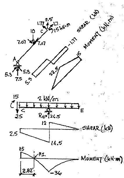
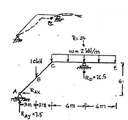
P5.24. Draw the shear and moment curves for each member of the frame in Figure P5.24. Sketch the deflected shape


5-28
Copyright © 2018 McGraw-Hill Education. All rights reserved.
without the prior written consent of McGraw-Hill Education.
No reproduction
or distribution
6 m C 10 kN B w = 2 kN/m D E A 3 m 3 m 6 m 6 m P5.24 Reactions + ΣF x = 0 : RAy = 0 + ΣMA = 0 : 10´3+24(12)-R D12 = 0 RD = 26.5 kN + ΣF y = 0 : RAY -34+26.5= 0 RAY = 7 5kN
P5.25. Draw the shear and moment curves for
each member of the frame in Figure P5.25.
Sketch the deflected shape hinges at B and C.
Member CD
Member AB
Deflected Shaps
Copyright © 2018 McGraw-Hill Education. All rights reserved.
or distribution without the prior written consent of McGraw-Hill Education.
5-29
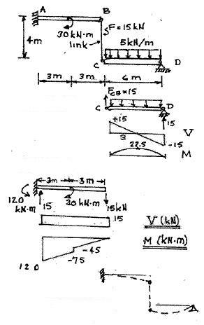
w = 5 kN/m
No reproduction
A
B 30 kN m
4 m C D 3 m 3 m 6 m P5.25
Link BC Carries Axial Load Only.
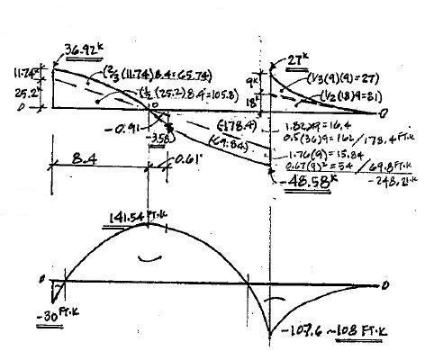
P5.26. Draw the shear and moment curves for the beam in Figure P5 26 Sketch the deflected shape.
Copyright © 2018 McGraw-Hill Education. All rights reserved.
without the prior written consent of McGraw-Hill Education.
5-30
No reproduction or distribution
ç y y
w2 = 6 kips/ft w1 3 kips/ft w3 = 2 kips/ft A C 30 kip ft 9ʹ B 9ʹ 9ʹ P5.26 + ΣM = 0; -30 ft k +27(4.5)+13 5(6¢)+36k (15¢+18¢)- B A y B = 75 58k + ΣF y = 0; -27-13.5-2(36)+75.58+ A y = 0 FBD: Sim-Triangles A = 36.92k 3k/ ft 9¢ = y x Y = x 3 ΣF = 0; 36.92k -3x1 x æ xö ÷ ÷= 0 y V = 0@x = 8.394 2 ç è3÷ ø x 2 Shear @x = 9¢ V =-36.92+3x + = -3.58k 6 @x =8 4¢ DM = ò Vdx x 2 ΔM = ò 36.92 dx +ò-3xdx +ò- dx 6 = 36.92xò 8 40 3x 2 ò 2 8 4¢0 x 3 ò 15 8 4¢ 0 =171.5 M@8.4¢ =171.4 ft k-30 ft k = 141.5 ft k Max + M Moment Deflected Shape
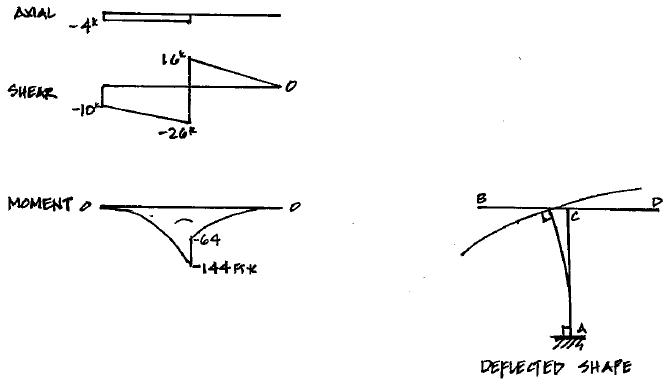
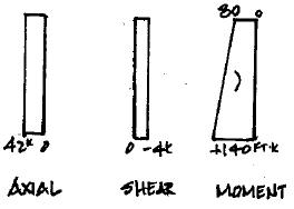
P5.27. Draw the shear and moment curves for each member of the frame in Figure P5 27. Sketch the deflected shape.
Copyright © 2018 McGraw-Hill Education. All rights reserved.
without the prior written consent of McGraw-Hill Education.
5-31
No reproduction or distribution
A y x
4 kips B 10 kips w 2 kips/ft C D 15ʹ A 8ʹ 8ʹ P5.27 + ΣM = 0; -4 k (15¢)-10k (8¢)+ M = 0
A A M =1401 k + ΣF = 0; -10k -32k + A = 0 y y + A = 42k ΣF = 0; -4k + A = 0 x x A = 4k
Column “AC”:
Beam: “BCD”
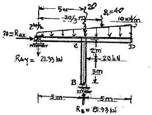
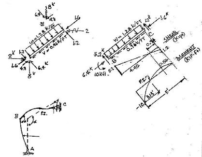
P5.28. Draw the shear and moment curves for each member of the frame in Figure P5 28. Sketch the deflected shape
Copyright © 2018 McGraw-Hill Education. All rights reserved.
without the prior written consent of McGraw-Hill Education.
5-32
No reproduction
or distribution
2 kN/m A 10 kN/m D C 20 kN 5 m 3 m B 5 m 5 m P5.28 + æ20 ΣM 0; 20(5m) 40 5R 20(2m) 0 = + ç ÷- + = A ç è 3 ÷ ø B RB =81.33 kN + ΣF y = 0; -60 kN
RAY = 0 RAY =
kN
+81.33-
21.33
P5.29. Draw the shear and moment curves for each member of the frame in Figure P5 29. Sketch the deflected shape
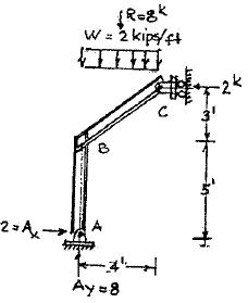
Reactions:
+ ΣMA = 0 =-C x 8+8´2 C x = 2 kips + ΣF x = 0 = A x -2 \ A x = 2 kips


+ ΣF = 0; A =8 kips y y
Member AB
Member BC
Deflected Shape
5-33
Copyright © 2018 McGraw-Hill Education. All rights reserved.
or distribution without the prior written consent of McGraw-Hill Education.
3ʹ 5ʹ B w 2 kips/ft A 4ʹ P5.29 C
No reproduction
P5.30. Draw the shear and moment curves for each member of the beam in Figure P5.30 Sketch the
cted shape The shear connection at B acts as a hinge.
Copyright © 2018 McGraw-Hill Education. All rights reserved.
without the prior written consent of McGraw-Hill Education.
5-34
No
reproduction or distribution
w = 12 kips/ft 6 kips/ft 6 kips A B C D hinge 6ʹ 3ʹ 3ʹ 2ʹ P5.30 FBD of segment BCD ΣMB = 3(6 6)-3C y +8(6)= 0 MA -156 kip-ft 12 kips/ft 6 kips/ft 6 kips C y = 52 kips ΣF y = B y -6⋅6+52-6 = 0 B y =-10 kips FBD of segment ABC ΣMA = MA +3(12⋅6)-6(10) = 0 MA =-156 kip ft ΣF y = A y -12 6+10
A y
kips Shear (kips) Moment (kip-ft) Ay = 62 kips 62 -152 4 2 0 84’ B -10 C Cy = 52 kips 23 8 -28 -57 D 6 -12 Deflected Shape
defle
= 0
=62
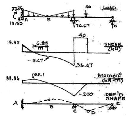
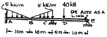
P5.31. Draw the shear and moment curves for each member of the beam in Figure P5.31 Sketch the deflected shape.
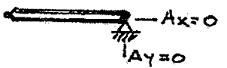
Member DE
All Forces = Zero
Since No Loads Applied
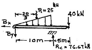
Member BCD
Reactions + ΣM = 0: 25´ 20 +40(15)-10R = 0 3
RC = 76.67 kN + ΣF y = 0: -B y -25-40+76.67 = 0
B y =11.67 kN Entire Structure
ΣF x = 0: B x = 0
Member AB
5-35
Copyright © 2018 McGraw-Hill Education. All rights reserved. No reproduction or distribution without the prior written consent of McGraw-Hill Education.
B C
5 kN/m 5 kN/m 40 kN E A B C D 10 m 10 m 5 m 10 m P5.31
P5.32. Draw the shear and moment curves for the beam in Figure P5 32 Sketch the deflected
w = 9 kN/m B shape. A C
w = 9 kN/m
6 m 6 m
P5.32
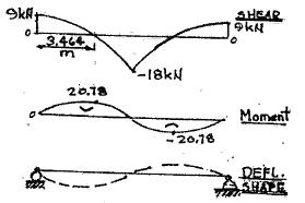
Reactions
Resultant of distni loads each side of £
R = 1 6´9 = 27 kN
+
2
ΣMA = 0; 27´4-27(8)+12 RC = 0
RC = 9 kN , RA = 9 kN
5-36
Copyright © 2018 McGraw-Hill Education. All rights reserved. No reproduction or distribution without the prior written consent of McGraw-Hill Education.
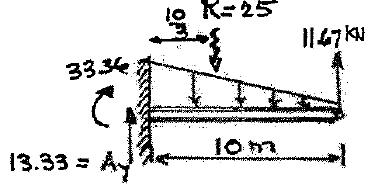
P5.33. Draw the shear and moment curves for the indeterminate beam in Figure P5.33 Reactions at support A are given. Sketch the deflected shape.
ΔMAB =-1.69´8=-13.52 kip ft
4.5-13.52 = -9.02 kip⋅ft
Locate Point of Inflection
13.5 = 3.375
y x 4x = y
ΔM = AreaV -Diagram
13.76 = 1 yx = 1 (4x)x 2 2
x 2 = 13.76 = 6.88 2
x = 2.62¢
5-37
Copyright © 2018 McGraw-Hill Education. All rights reserved.
or distribution without the prior written consent of McGraw-Hill Education.
No reproduction
4.5 kip ft A 1.69 kips w = 4 kips/ft B C 8ʹ 6ʹ 15.19 kips 10.5 kips P5 33
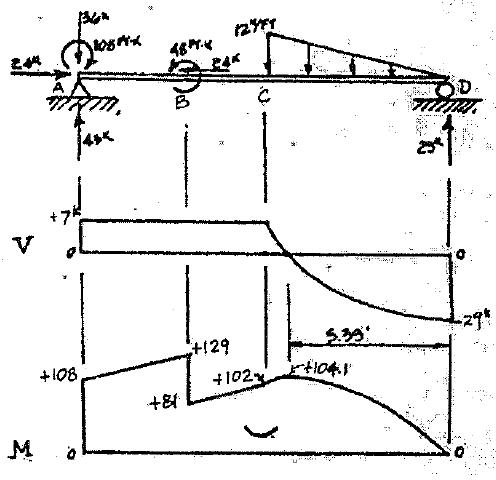
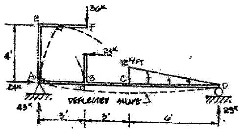
P5.34. Draw the shear and moment curves for the beam in Figure P5 34 Sketch the deflected shape.
Copyright © 2018 McGraw-Hill Education. All rights reserved.
or
without the prior written consent of McGraw-Hill Education.
5-38
No
reproduction
distribution
P = 36 kips 3ʹ E F P = 24 kips w = 12 kips/ft 4ʹ 2ʹ B C A D 3ʹ 3ʹ 6ʹ P5 34
Structure
Entire
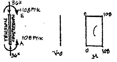
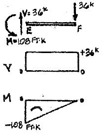
Isolate Cantilever EF
Isolate AE
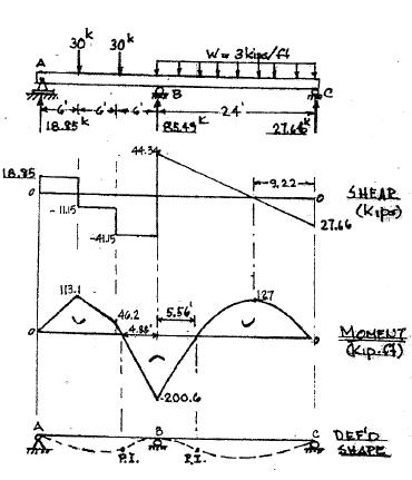
the beam in Figure P5 35 Reaction at support B is given. Locate all points of zero shear and moment. Sketch the deflected shape. A
Copyright © 2018 McGraw-Hill Education. All rights reserved.
without the prior written consent of McGraw-Hill Education.
5-39
No reproduction or distribution
= 3 kips/ft C B 6ʹ 6ʹ 6ʹ 24ʹ RB = 85.49 kips P5.35
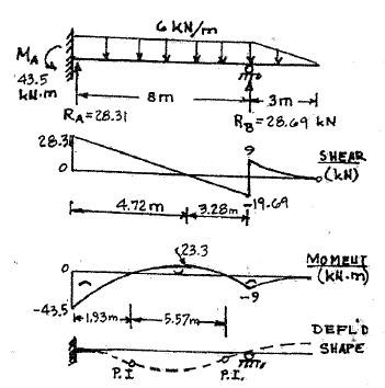
P5.36. Draw the shear and moment curves for each indeterminate beam Reactions are given Label maximum values of shear and moment Locate all inflection points, and sketch the
Copyright © 2018 McGraw-Hill Education. All rights reserved.
without the prior written consent of McGraw-Hill Education.
5-40
No reproduction
or distribution
43.5 kN m A w = 6 kN • m C B deflected shape. RA = 28.31 kN 8 m RB 28.69 3 m P5.36
P5.37. Draw the shear and moment curves for
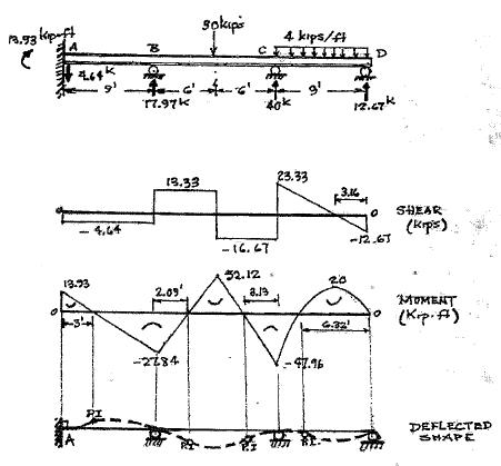
each indeterminate beam. Reactions are given. Label maximum values of shear and moment. Locate all inflection points, and sketch the
5-41
Copyright © 2018 McGraw-Hill Education. All rights reserved.
or distribution without the prior written consent of McGraw-Hill Education.
No reproduction
30 kips 13.93 kip ft w 4 kips/ft
A B C D deflected shape. 9ʹ 6ʹ 4.64 kips 17.97 kips 6ʹ 9ʹ 40 kips 12.67 kips P5 37
P5.38. Draw the shear and moment curves and sketch the deflected shape.
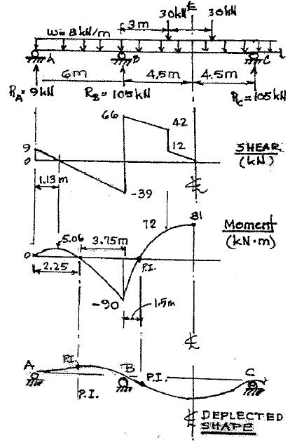
Since Structure Symmetrical Analyze Left Half
5-42
Copyright © 2018 McGraw-Hill Education. All rights reserved.
without the prior written consent of McGraw-Hill Education.
No reproduction
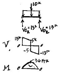
w 8 kN/m 30 kN 30 kN
or distribution
3 m 3 m A D B C RA 9 kN RB 105 kN RC 105 kN RD 9 kN 6 m 9 m 6 m P5 38
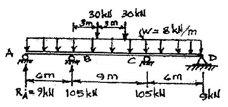
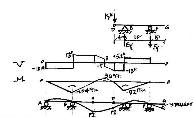
P5.39. Draw the shear and moment curves and sketch the deflected shape.
5-43
Copyright © 2018 McGraw-Hill Education. All rights reserved.
the prior written consent of McGraw-Hill Education.
No reproduction or distribution
y y
without
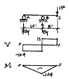
P = 10 kips w 2 kips/ft G A B C D E F 10ʹ 8ʹ 4ʹ 4ʹ 4ʹ 10ʹ 5ʹ P5.39 FBD “CD”: By Symmetry: V = V = 1 (10k +2k/1(8¢))= 13k CR DL 2 FBD “ABC”: + ΣM = 0; 13k (18¢)- B (10¢)= 0 B = 23.4k A y y + ΣF = 0; - A +23.4k -13k = 0 A =10.4k y y y
“DEFG”: ΣM = 0; -13k (4¢)-F (10¢)= 0 E y F = 5.2k + ΣF = 0; -13k + E -5.2k = 0 Entire STR: y y E =18.2k
FBD
Deflected Shape:
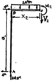
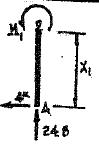
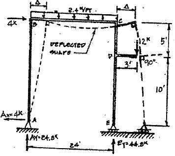
P5.40. (a) Draw the shear and moment curves for the frame in Figure P5.40 Sketch the deflected shape. (b) Write the equations for 4 kips
shear and moment in column AB Take the origin at A (c) Write the shear and moment equations for girder BC. Take the origin at
Copyright © 2018 McGraw-Hill Education. All rights reserved.
without the prior written consent of McGraw-Hill Education.
5-44
No reproduction
2 2 æ x ö 1 1 x
or distribution
w
B C 12 kips
x2 D 15ʹ 5ʹ F 10ʹ joint B 1 A E 24ʹ 3ʹ P5.40 Segment ABC: Origin CD; Range 0 ≤ x2 = 2 4 + ΣF y = 0; k 24.8 -2.4x2 -V2 = 0 V = 24.8-2.4x + ΣMO = 0; 24.8x +4k (15¢)-2.4x 2 ÷ - M = 0 2 2 ç è ÷ 2 ÷ ø 2 M = 60+24.8x -1.2x 2 2 2 2 Segment AB, Orgin @ A, Range 0 ≤ x, ‒ 15′ Segment BC + ΣMO = 0; +4x1 - M1 = 0 M = 4k Segment CE
= 2.4 kips/ft
