THE CLEATOR MOOR HUB
 STUDIO 3.2 - LUIS ESCRIBANO

Education
Bachelor of Architecture BArch
Manchester School of Architecture, Manchester (UK) sept. 2021 - jun. 2024
IB Diploma + American High School Diploma EF International Academy, New York (USA) sept. 2019 - jun. 2021
International Baccalaureate
SEK International Schools, Madrid, Dublin and Megève sept. 2005 - jun. 2019
Experience/Internships
HORIZON Fletcher|Rae Architects (UK)
RIBA Future Architects Student Mentoring Program nov. 2022 - apr. 2023
JUNQUERA Arquitectos (Spain)
Architectural Internship, full-time nov. 2020 - dec. 2020
RAFAEL DE LA-HOZ Arquitectos (Spain)
Architectural Internship, full-time dec. 2020 - jan. 2021
Volunteering
VOLAN Association (Spain) jun. 2019 - sep. 2019
Volunteered at low-income elderly homes in Madrid, organizing activities and providing support to the residents.
National Honor Society (US) sep. 2018 - jun. 2021
President of the High school’s NHS division. Organized and participated in fund-raising projects and events.
Languages
Spanish (Native)
English (Native)
French (DELF B2; professional working level)
Italian (basic knowledge)
Luis Escribano
Phone: (+44)07916213791 (+34) 678.433.522
E-mail: luis.escribanocoloma@gmail.com
Address: Ave. Lazarejo 99, Las Rozas, 28232 Madrid (Spain)
Linkedin: linkedin.com/in/luis-escribano-1707a6291
Licenses & Certificates
Design Performance for Climate Action License Passivahus Trust & Coaction jan. 2024 - jun. 2024
Manchester School of Architecture (MSA) (UK) MSA Live 2022 & 2023 may. 2022 - jun. 2023
RIBA Future Architects Mentoring (UK) Credential ID 20049675 nov. 2022 - apr. 2023
National Honor Society (US)
President of the EF New York Academy’s Chapter aug. 2020 - jun. 2021
Knowledge & Skills
Software
AutoCAD
Rhino 3D
SketchUp
Revit
Blender
Enscape
Grasshopper
HTFlux
Therm
Adobe Creative Suite (Photoshop, Illustrator, InDesign, Lightroom)
Areas of Interest/Expertise
Building Information Modelling (BIM)
Computational Design
Urban Design
Building Energy Analysis
Passivhaus
Photography
Sketching
THE CLEATOR MOOR
EDUCATION & TRANSPORT HUB
LUIS ESCRIBANO

3 - 4 STUDIO 3.1 OVERVIEW 5 STUDIO 3.2 DESIGN DRIVERS 6 - 7 SURVEYING THE CLEATOR MILL - AN OVERVIEW 8 - 9 RESTORATION PLANS 10 - 16 PROPOSED STRUCTURE 10 - 12 PARAMETRIC COLUMN ITERATIONS 13 - 15 STRUCTURAL ANALYSIS 16 CONSTRUCTION PROCESS 17 - 19 THE EXTENSIONS 20 -21 ENVIRONMENTAL STRATEGIES & TACTILE DETAIL 22 MASTERPLAN 23 - 25 FLOORPLANS 26 - 27 ARCHITECTURAL VISUALIZATIONS 28 - 31 RENDERS IN PROGRESS INDEX
Public transport services create only one viable movement corridor along the coast. The rest of the services are infrequent and isolate communities
3.1 SITE ANALYSIS & COMMUNITY SURVEYING: IDENTIFYING AREAS OF FOCUS
During the developent of our Studio 3.1 project, the infrastructure Space atelier had a very strong objective of creating meaningful impacts on the community through our projects, and therefore our interventions where guided by meticulous analysis of the community and its needs.
In my explorations, I was driven to the lack of public transportation in the area and the underfunded condition of educational facilities. Through further explorations I hypothesized that maybe there was a relationship between lack of accessibility to educational opportunities and the region’s below average academic performance.


outside the
were
A new transport system focused in connecting students to their educational facilities should provide flexible
3.1 PROJECT PROPOSAL: DRT & EDUCATIONAL HUB
My proposal aimed to create a centralized hub for public transportation and modern educational facilities for all students in the region who attend facilities that individually don’t have t he budget for these installations within their premises. This would create a sense of collaboration and commuinity, promoting growth.


DEMAND RESPONSIVE TRANSPORT FROM STUDENTS’ HOME TO EDUCATION HUB
- Pick-up directly from student home
- Pick-up of other students en route to education hub
- Reduced travel times
- Safe travel method


LEARNING AND NETWORKING OPPORTUNITIES AT EDUCATION HUB
- Transfer in a warm, safe and comfortable environment
- Learning opportunities in Education Hub
- Knowledge exchange between institutions
- Community spaces like galleries or theatres

DEMAND RESPONSIVE TRANSPORT FROM EDUCATION HUB TO LOCAL INSTITUTIONS
- Transfer direct to educational institutions
- Higher capacity vehicles for larger student numbers
- Choice to access different institutions
- Safe travel method
low-capacity
safe
reliable manner.
rides along non-serviced communities in a
and
non-existent.
Areas
coastal corridor
public transport services are irregular, cancelled or
PUBLIC TRANSPORT Primary Schools Secondary Schools Colleges University Campus Site Train Line Hourly Bus Service Daily Bus Service Bi-Weekly / Weekly Service Bus Stop Train Station
EDUCATION INSTITUTIONS VS
3.1 PROJECT DEVELOPMENT


PROPOSED SITE RELOCATION & INITIAL MASTERPLAN
The site allocated by the Infrastructure atelier is located in Cleator Moor, a small village in the Cumbrian Coast. Initially, the plot of land for our intervention was fixed at a large parking lot currently functioning as a Park & Ride facility. This parking lot was part of the larger complex of the 1800s Cleator Mill, most recently the Kangol Factory, a historic complex that had already seen parts of it demolished. In order to prevent further architectural loss, I changed the emplacement of my site to this remaining building.
INTERVENTION DEVELOPMENT AND INITIAL GENERAL ARRANGEMENTS
Renovations had long captivated me and having the opportunity to work in one as part of my BA3 experience was extremely enriching., although challenging at times.
After reaching out to many different architects and consulting different sources, I developed an early renovation strategy which seeked to preserve the majority of structurally stable elements of the building while creating a non-invassive extension of the building to host the desired community spaces.
COMPLEX SURVEYING; UNDERSTANDING ARCHITECTURAL HERITAGE
Having had no experience in architectural renovations or working with historic structures of the sort, the surveying process was challenging. With the site being hundreds of kilometers away and only having visited the complex once, most of the research was based on previous documentation of rejected intervention proposals and some measurements taken on site.
 The bus interchange will count with covered boarding platforms for shelter.
Equipped with a library, classrooms, an art gallery and amphitheatre
A car free playground area for the younger kids to play
Recovering the historic mill race which is still laying in good shape under the main road
Maintaining the recently built park and ride plot in the complex
Separating car and bus circulation providing faster flowing services.
The Bus Interchange
The Education Hub
The Green
The Mill Race
Park and Ride
New Accesses
The bus interchange will count with covered boarding platforms for shelter.
Equipped with a library, classrooms, an art gallery and amphitheatre
A car free playground area for the younger kids to play
Recovering the historic mill race which is still laying in good shape under the main road
Maintaining the recently built park and ride plot in the complex
Separating car and bus circulation providing faster flowing services.
The Bus Interchange
The Education Hub
The Green
The Mill Race
Park and Ride
New Accesses
3.2 DESIGN DRIVERS FOR INTERVENTION
RESTORATION

One of the main drivers of the project was the restoration of the Cleator Mill building, maintaining one of the few historic architectural sites in the area and preventing from following the same fate of the rest of the complex which is just a pile of rubble.
The renovation seeks to maintain salvage as much of the original structure as possible, while creating a space that fosters education and community. The restoration aims to maintain as much character from the original construction without replicating what it once was.
CONNECTION

Connecting the communities around the new transport and education Hub is the second driver of the project. The intervention must be architecturally viable and conserve aesthetics while providing functionality for the transport centre aspect of it.
Suited to host a small DRT system, the space must be able to hold a series of buses and minibuses as well without disrupting the current park & ride flow. This new connectivity of students will result in a strenghtening of community bonds through the area which are sometimes isolated due to the difficulty of reach between towns and villages
EDUCATION

The Hub seeks to provide spaces that educational facilities don’t have the facilities or funds for, such as specialized daycares, computer labs and group study classrooms. These spaces seek to create a network between the students in the area, fostering community interactions and knowledge interchange by grouping students together. These interactions will be pushed by large open spaces that incite collaboration between students.
The combination of a transport hub within these facilities will provide an opportunity for students to access these new facilities instead during their much shorter and cheaper commutes.
THE CLEATOR MILL - ORIGINAL STRUCTURE & CURRENT CONDITION

The Cleator Mill is saldy in a state of almost complete disreapair. The roof has crumbled and damages the structure of the second floor. A vast majority of the steel beams that hold the structure are rusting quickly due to its full exposure to weathering and the brick lining of the walls is also suffereing from mold and aging. The structure is sitting with no protection and all openings are unframed after a recent removal citing structural compromise.

The main sandstone structure of the building was built in the year 1800 and has remained in good condition over the years due to its durability. It is unclear when furhter additions were added due to lack of documentation but the building was renovated several times, adding the current brick lining of the walls and steel structure. All of the more recent additions to the building have fallen in disrepair after the closing of the Kangol factory and lack of regular maintenance.

Using the measurements taken on site, as well as plans from previous planning applications, and the Lidar surveying of the building with drones, there was sufficient information to create an accurate model of the building’s structure if it hadn’t been damaged.


 The top floor included a series of steel trusses and battens that held up a slate roof. This has mostly disappeared today.
The steel columns and beams hold a vaulted brick ceiling in the bottom floor. Most of these beams and bricks will need replacing.
The top floor included a series of steel trusses and battens that held up a slate roof. This has mostly disappeared today.
The steel columns and beams hold a vaulted brick ceiling in the bottom floor. Most of these beams and bricks will need replacing.
2024 BUILDING
ORIGINAL STRUCTURE 1800 - 1991
CONDITION VISUALIZING ORIGINAL STRUCTURE
Brick and concrete foundations from 1800
Original stairs, fire regulation compliant
Walls are room partitions and non-load bearing
Vaulted ceiling held by steel columns
Walls are supported by internal steel columns
Steel roof trusses and battens
Point of connection between steel beams and roof trusses
Stone cornice and adornments
Steel beams are heavily deteriorated and covered in a led base paint which would need to be removed. The structure is compromised
B - Door Frames
Stone door frames are damaged and not adequate for current standards
C - Window Frames
Stone window frames are damaged from previous steel window frames
D - Walls
Stone walls are in stable condition but internal brick lining is rotting and unstable
A - Steel Beams A - Steel Beams
Steel beams are mostly knocked down by the detachment of the roof and therefore must be removed. Roof is in ruins.
B - Wall - Cornice
Wall cornice connection is intact and in good shape due to the red sandstone’s durability
C - Window Frames
Stone window frames are damaged from previous steel window frames
D - Walls B
Stone walls are in stable condition but internal brick lining is rotting and unstable

Ground floor partition walls are non-loadbearing and therefore can be removed
Stairs are in good condition on the ground floor and are compliant with K1 1.3 to be a utility staircase and with part B1 2.18 for width of fire escape
Ground Floor Collage of Current Condition Second Floor
Using photos taken on the site during the Cumbria site trip in early October, as well as a collection of images obtained from the Lidar Survey digital model this piece was created. The digital model allowed to bring in images that accurately show the state of the detached bricks, roof and steel columns of the second floor as access was restricted to this area.
Scans show remaining pieces of slate still latched on to the sparce sections of the roof that haven’t crumbled. Steel trusses and battens are rusted and close to collapsing.
Second floor has no partitions, floor needs to be restabilized due to its deterioration
Adornments have been damaged due to weathering and vegetation growth, with some of the cubes missing and having detached.

Window and door frames are empty and need replacing to current standards.
Stairs are in poor condition on the second floor, however they are compliant with K1 1.3 to be a utility staircase and with part B1 2.18 for width of fire escape
There is large amounts of red sandstone bricks around the building due to the demolition of several other buildings of similar size in the Kangol Mill complex, allowing for recycling in the expansion.
The condition of the first floor is dire, with the remains of the detached roof compromising the structural stability of the steel beams and entire building.
THE CLEATOR MILL - ORIGINAL STRUCTURE & CURRENT CONDITION
A A
B C C D D


- Original Sandstone Cornice
- Wood Coldblock
- 300mm Steel Support Bracket
- 25mm Oriented Standard Board
- 150mm Polystyrene Insulation
- 25mm Oriented Standard Board
- 200mm Reinforced Glulam Column
- 3mm Vapor Membrane
- 3mm Waterproof Membrane
- 560mm Original Sandstone Wall
- 15mm Acoustic Plasterboard
- 15mm Fire Proof Plasterboard
- 300mm Steel Support Bracket
- 25mm Oriented Standard Board
- 150mm Polystyrene Insulation
- 25mm Oriented Standard Board
- 200mm Reinforced Glulam Column
- 3mm Vapor Membrane
- 3mm Waterproof Membrane - 200mm Void
- 360mm Original Sandstone Wall Sandstone Wall
Buildup: - 30mm Wood Parquet Finish - 3mm Waterproof Membrane - 25mm Oriented Standard Board - 150mm Polystyrene Insulation
& Wall Buildup:
15mm Acoustic Plasterboard
15mm Fire Proof Plasterboard
Bracket
Sandstone - Column
Buildup & Foundations: - 30mm Wood Parquet Finish
200mm Reinforced Glulam Column Joint & Wall Buildup: - 15mm Acoustic Plasterboard - 15mm Fire Proof Plasterboard - 300mm Steel Support Bracket
- 25mm Oriented Standard Board
- 80mm Screed
- 10mm Steel Tubes for Underfloor Heating
- 25mm Oriented Standard Board
- 150mm - 300mm Polystyrene Insulation
- 350mm Brick Foundations - 5000mm Concrete Foundations
- 25mm Oriented Standard Board - 100mm Polystyrene Insulation - 25mm Oriented Standard Board - Steel Plate Joint - Steel Bolts + Nuts
- Steel Sandstone - Column Joint - 200mm Reinforced Glulam Column - 200mm x 500mm Concrete Base for Glulam Column
- 250mm Steel Screws - 200mm Void - 360 - 560 mm Original Sandstone Wall - 3mm Waterproof Membrane
Floor
Floor
- 100mm CLT plans - 200mm Reinforced Glulam Beams
2024 BUILDING ELEVATION PROPOSED SECTION PROPOSED RESULTING ELEVATION 1 1: CORNICE DETAIL 2: WALL BUILDUP 3: WALL - INTERMEDIATE FLOOR JOINT 4: WALL - FLOOR - FOUNDATIONS 2 3 4 PLANNED RESTORATION: SECTION AND ELEVATION Joint
-
-
-
-
- 300mm Steel Support
- 25mm Oriented Standard Board - 100mm Polystyrene Insulation - 25mm Oriented Standard Board - Steel Plate Joint
Steel Bolts + Nuts
Steel
Joint -
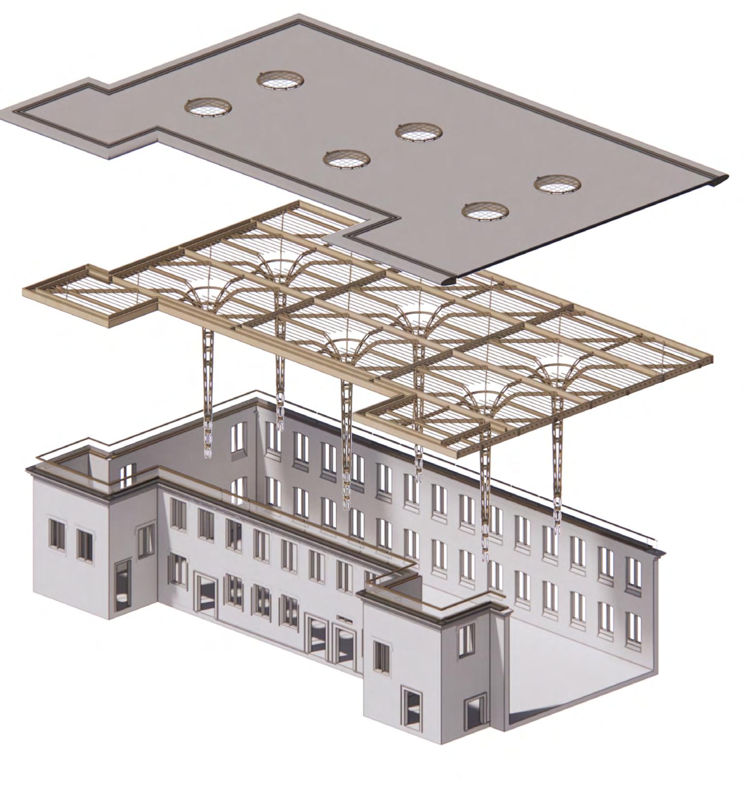
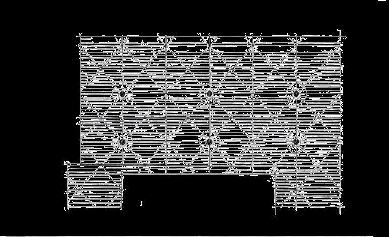
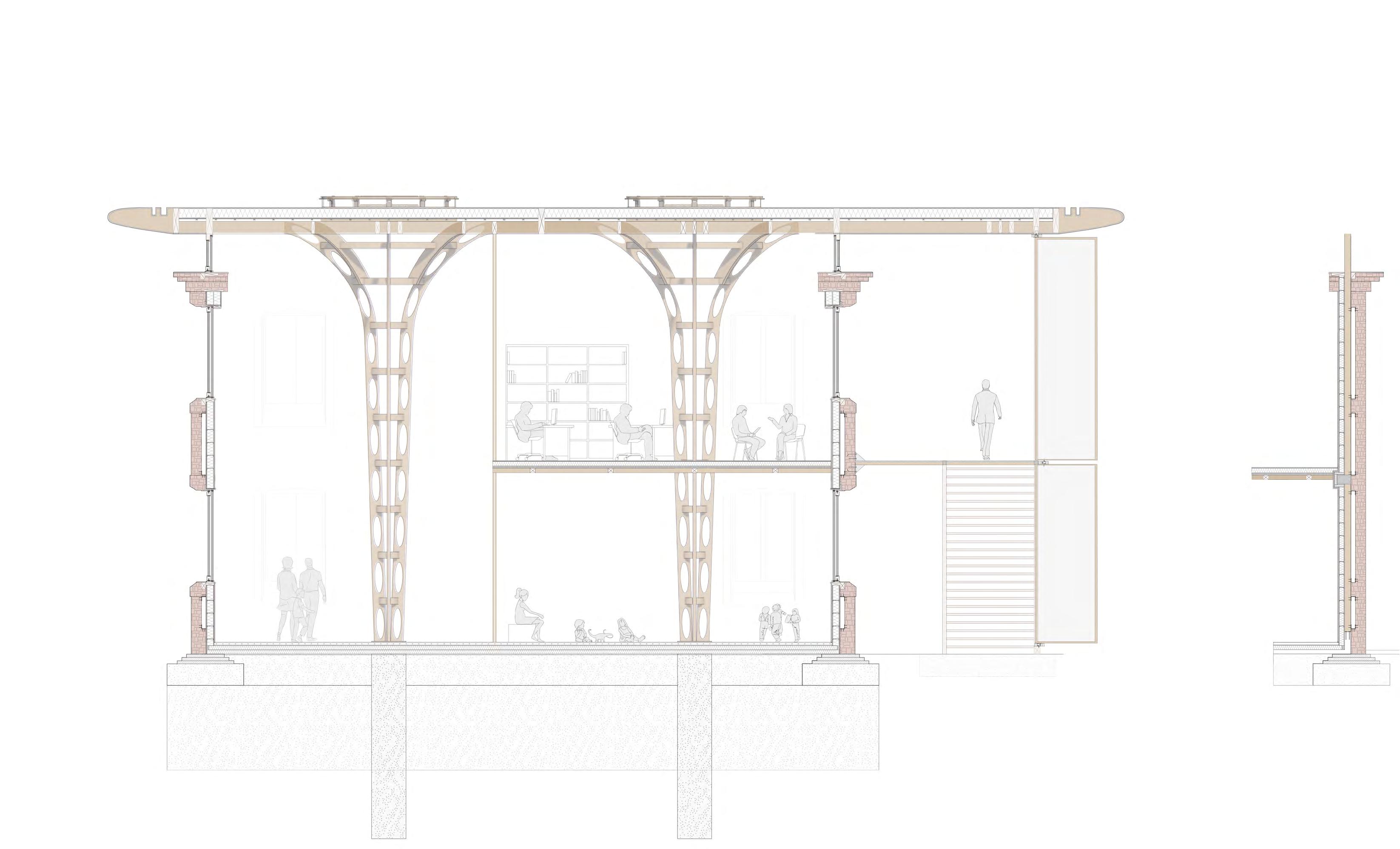
PARAMETRIC STRUCTURAL GRID: ROOF & COLUMNS
In an attempt to create a structural grid that would allow to participate in both areas of the project, the renovation and extension of the Cleator Mill, a CLT structural grid was developed which created a constant rythm between both buldings while creating a visual distinction between old and new.
When cplanning the intervention, it was decided that it would be best to create a smooth boundary between old and new, one that would symbolize change without driving away from its historical heritage. The creation of a sleek roof that sat one meter above the historic structure, visually separated by glass crcreated distinction without separation into two different entities. The materiality choice of perforated CLT managed to create the illusion of larger internal spaces while seeiming lightweight from the exterior, as if floating.
Early sketches of the CLT grid pattern resulting in the combination of the columns with their respective branching beams and the perpendicular beam grids
Early sketches of the structural grid within the restored building, exploring the relationship between columns and roof
COLUMN DESIGN, ITERATIONS AND MODELLING
The first prototype for the columns followed the shape of my initial design for Studio 3.1. The column consisted of 4 pierced individual 90mm thick columns that started joint at the base and expanded as they reached the roof. The idea behind the piercings on each column was to reduce the need for additional material that could be repurposed as the gutter shapers in my design. FIRST PROTOTYPE: 4 INDIVIDUAL COLUMNS SECOND PROTOTYPE: 4 INDIVIDUAL COLUMNS AND A 5M DEEP BASE
Solution: In order to tackle such a large bending motion in the first prototype was adding a base at the bottom of the columns that would go deep into the ground and act as the main support point.


Columns start losing shape outwards and experience quite a large bending deflection. Proximity to the base made me think that more support would be needed below
Following the shocking results from the first round of testing, it was clear that some measures needed to be implemented to achieve a successful column design. The first of these measures was to provide a base, which I thought would provide much greater stabilization and less deflection throughout.
Solution: In order to tackle the issue of bending, decided that some sort of brackets or braces that joined the individual columns together was needed

THIRD PROTOTYPE: 4 INDIVIDUAL COLUMNS AND RING BRACES
The third prototype was tested after implementing the measure of adding the 9 ring braces to hold the columns together. There is significant improvement in comparison to the previous prototypes. Not only did the individual columns not bend outwards but the total deflection was minimal. However, it still experienced a significant reaction to the load which would not be able to sustain the weight of the structure through time.


Downward deflection of top part of the individual columns demonstrates that load is too heavy for current 4 contact points; must be redistributed.
Columns still bend outwards excessively, although the columns lose less height after being compressed. Base seemed to provide additional support.
FOURTH PROTOTYPE: 4 PIERCED COLUMNS + 4 FULL COLUMNS + Ring BRACES
After identifying that the 4 contact points for the column were too few for the total load to be distributed along them, I created a fourth prototype that included an additional 4 non-pierced columns. This was done with the intention of providing more overall stability to the structure and adding 4 more contact points with the roof grid that would distribute the weight better and avoid downward deflection.
PHYSICAL MODEL CREATION: LASER CUTTING THREE FURTHER ITERATIONS
After having tested the 3 following prototypes on the SNSPro software in Rhino, the results were much more promising, so decided to model all of the individual columns by hand in order to get a better perception of their structural capabilities as well as other factors such as their appearance and that of the shading they created after being exposed to the light coming from the skylights above them.

In an attempt to model the columns as precisely as possible to their actual form, decided to use natural wood, MDF, and scaled them down to 1:20 scale.
After completing the testing for the new prototype, the results were very satisfactory and there was no downward deflection of the columns


PROTOTYPE SOLUTION: CLT BRACES AND STEEL JOINTS
After the two attempts at testing the column protoypes showed that the bending of the individual columns was excessive, a system of CLT braces in the form of circular rings was designed in order to tie the columns.


FINAL COLUMN PROTOTYPE: 4 PIERCED CLUMNS + 4 PARTIAL COLUMNS + BRACES
In an attempt to reduce the amount of CLT needed to produce each column, decided to explore an option that would still provide additional contact points to avoid a downward reflection as figured out through the testing of the third prototype. This option combines smaller pieces at the top of the column to provide a total of 8 contact points that should prevent downward deflection.


The SNSPro testing showed great results, with no downward deflection, even at higher loads, proving increasing the contact points was the solution to the deflection issue.
All individual columns are held together by the braces, including the 4 additional segments added to the column that don't reach its base.
Click for video simulation
Click for video simulation Click for video simulation
Click for
video Click for video
CLT Rings and Steel Braces
MDF Modelled Iterations, Scale 1:20
1:20 Column Physical Models and
Iterations


Although the physical modelling process was challenging I think that it provided a great understanding of the relationship between all of the components that compose the columns and how they come together. It is true that it is not of utmost fidelity due to the pieces being laser cut rather than stress bent as the glulam columns would, or the materiality, but it still managed to fulfill its role and shed light to the design process.
THE CORNICE: END OF GRID AND MEETING POINT THE WINDOWS: THERMAL BARRIERS


THE FOUNDATIONS: REINFORCING OLD FOUNDATIONS THE FRAGMENT: 3mm PVC Waterproof Membrane on Aluminum Cladding Sheet 200mm Polystyrene Insulation 10mm Corrugated Steel 30mm Acoustic & Fire Proof Plasterboard Skylight Hinge Triple Glazed Glass Panel Skylight Support Beams Skylight CLT Base Skylight Lid Permiter CLT Beam CLT Support Batons Diagonal Column Beam Grid Beams 90mm Individual Pierced Column 90mm Unpierced Column Fragment CLT Ring Brace Ring Brace Steel Braket 4 Point Steel Joint 6 Point Steel Joint Steel Base Plaque Steel Bolts and Nuts Underground CLT Column Extension 5m Poured Concrete Column Foundation Existent Mill Sandstone Wall Existent Mill Sandstone Cornice 3mm PVC Waterproof Membrane on Aluminum Cornice Shaper Recycled CLT Gutter Filling Primary Gutter to Downpour Secondary Gutter Window CLT Lintel Glass Panels Stool Internal CLT Stool Timber Sash Beam Reinforcing Chamber Composite Edge Bar Warm Edge Bar Spacer Gas Filling 4mm Triple Glazing Timber Sash Beam Steel Drainage Gutter Steel Stool CLT Cornice Cover 20 35 21 42 36 22 43 37 23 44 38 24 45 39 25 46 40 10 26 47 27 48 28 49 11 29 50 12 30 51 13 31 52 14 32 15 18 33 16 19 34 17 1 10 11 20 41 35 5 2 36 6 3 4 44 38 7 39 8 40 9 12 51 13 52 14 15 18 16 19 34 17 Wood Parquet Internal Flooring Finish 80mm Screed Layer with Piping Spacing Underfloor Heating Steel Piping 15mm Sheathing Board 200mm Polystyrene Insulation 3mm Waterproof Memberane 500mm Poured in Concrete 90mm Individual Pierced Column CLT Ring Brace Steel Base Plaque Steel Bolts and Nuts Undergroung CLT Column Extension 5m Poured Concrete Column Foundation Undertermined Internal Flooring 80mm Screed Layer with Piping Spacing Underfloor Heating Steel Piping 15mm Sheathing Board 200mm Polystyrene Insulation 3mm Waterproof Memberane 500mm Poured in Concrete Existent Mill Sandstone Wall 36 36 36 46 46 40 40 40 47 47 41 41 48 48 42 42 49 49 43 43 43 50 50 44 44 52 52 34 34 34 45 45
10 14 27 27 11 24 19 24 15 28 12 25 25 25 25 13 26 26 26 26 17 31 31 18 32 19 33 20 52 21 22 16 3mm PVC Waterproof Membrane + Alumnium Cornice Cladding Sheet Recycled CLT Cornice Shaper Gutter Filling Primary Gutter to Downpour Secondary Gutter Perimeter CLT Beam Window CLT Lintel Reinforcing Chamber Composite Edge Bar Warm Edge Bar Spacer Gas Filling CLT Support Batons Diagonal Column Beams Grid Beams Window Lintel Glass Panels Stool Internal CLT Stool Mill Sandstone Wall 4mm Triple Glazing Timber Sash Beam Steel Drainage Gutter Steel Stool CLT Cornice Cover Existent Mill Sandstone Cornice 10 14 27 11 24 19 15 28 12 25 13 26 17 31 18 32 19 33 20 52 21 22 16 30 29 30 29 29
ROOF BUILDUP CORNICE SKYLIGHTS ROOF GRID WINDOW EXISTENT MILL COLUMN FLOOR BUILDUP 1
MAIN STRUCTURE ANALYSIS
MAIN STRUCTURE ANALYSIS


THE NEW CORNICE: SHADE AND GUTTER SYSTEM THE SKYLIGHTS: VENTILATION AND LIGHTING SYS - THE JOINTS: ANGULAR JOINTS AND STEEL BRACKETS THE JOINTS: ANGULAR JOINTS AND STEEL BRACKETS 3mm PVC Waterproof Membrane on Aluminum Cornice Cladding Sheet Recycled CLT Cornice Shaper Gutter Filling Primary Gutter to Downpour 3mm PVC Waterproof Membrane on Aluminum Cornice Cladding Sheet Recycled CLT Cornice Shaper Gutter Filling Primary Gutter to Downpour Diagonal Column Beam Grid Beam 90mm Individual Pierced Column 90mm Unpierced Column Fragment Diagonal Column Beam Grid Beam 90mm Individual Pierced Column 90mm Unpierced Column Fragment CLT Ring Brace Ring Brace Steel Braket 4 Point Steel Joint 6 Point Steel Joint CLT Ring Brace Ring Brace Steel Braket 4 Point Steel Joint 6 Point Steel Joint Secondary Gutter Permiter CLT Beam CLT Support Batons Diagonal Column Beams Grid Beams Secondary Gutter Permiter CLT Beam CLT Support Batons Diagonal Column Beams Grid Beams 10 10 10 14 14 14 11 11 11 15 15 15 12 12 12 13 13 13 18 18 18 34 34 34 16 16 16 35 35 35 36 36 36 36 17 17 17 37 37 37 18 18 18 38 17 17 17 38 38 39 39 39 38 - Six Beam bracket 39 - Four Beam bracket
3mm PVC Waterproof Membrane on Aluminum Cladding Sheet 200mm Polystyrene Insulation 10mm Corrugated Steel 30mm Acoustic & Fire Proof Plasterboard Skylight Hinge Triple Glazed Glass Panel Skylight Support Beams Skylight CLT Base Skylight Lid Permiter CLT Beam CLT Support Batons Diagonal Column Beam Grid Beams 3mm PVC Waterproof Membrane on Aluminum Cornice Shaper Recycled CLT Gutter Filling Primary Gutter to Downpour Secondary Gutter 5 2 2 1 1 6 6 3 4 4 7 7 8 8 9 9 10 10 11 11 12 13 13 14 14 15 15 15 18 18 18 16 16 17 17 ROOF BUILDUP CORNICE SKYLIGHTS ROOF GRID 12 90mm Individual Pierced Column 90mm Unpierced Column Fragment CLT Ring Brace Ring Brace Steel Braket 4 Point Steel Joint 6 Point Steel Joint Steel Base Plaque Steel Bolts and Nuts Underground CLT Column Extension 5m Poured Concrete Column Foundation 35 35 42 36 36 43 43 37 37 38 39 39 40 40 41 34 34 COLUMN
- Skylight Hinge
- Triple Glazed Glass Panel
- Skylight Support Beams
- Skylight CLT Base
- Skylight Lid
- 3mm PVC Waterproof Membrane on Aluminum Cladding Sheet
- 200mm Polystyrene Insulation
- 10mm Corrugated Steel


- 30mm Acoustic & Fire Proof Plasterboard - CLT Support Batons - Diagonal Column Beam
- 3mm PVC Waterproof Membrane on Aluminum Cladding Sheet
- 200mm Polystyrene Insulation - 10mm Corrugated Steel
- 30mm Acoustic & Fire Proof Plasterboard
- CLT Support Batons - Diagonal Column Beam - Grid Beams
- 90mm Individual Pierced Column - 90mm Unpierced Column Fragment - CLT Ring Brace Floor Buildup: - 30mm Wood Parquet Finish - 3mm Waterproof Membrane - 25mm Oriented Standard Board - 150mm Polystyrene Insulation - 100mm CLT plansk - 200mm Reinforced Glulam Beams - 30mm Wood Parquet Finish
Column: - Internal 50mm Glulam column - 25mm Glass Partition
- 25mm Oriented Standard Board
- 80mm Screed
- 10mm Steel Tubes for Underfloor Heating
- 25mm Oriented Standard Board
- 300mm Polystyrene Insulation
- 25MM Oriented Standard Board
- 5000mm Concrete Foundations -
1:
2:
3:
FLOOR
4:
1
SKYLIGHT - ROOF
COLUMN - ROOF
INTERNAL WALL - INTERMEDIATE
JOINT
FLOOR & FOUNDATIONS:
2 3 4
STEP 1: TEARING DOWN DAMAGED SURFACES & SUPPORTING WALLS
Wall retainment system designed to provide a resting point for the walls to lean on and prevent them from destabilizing. After components are removed, these will be placed behind the wall to facilitate the removal of flooring.


Ruinous Condition
Sadly, the mill has been inoperative for many years now and the factory has fallen out of shape severely. With the internal columns, roof and internal brick lining all rotting and collapsing, everything except for the external sandstone walls would need to be removed with specialized machinery like cranes and much care as to not destabilize the structure.

Brackets drilled into the foundations and walls to act in place of the removed components previously in place.
STEP 4: INSTALLING COLUMNS & WINDOWS
Heavy machinery such as cranes are needed in this step in order to transport the heavy and tall planks that make up the body of the column, while a ground team prepares the installation.

CONSTRUCTION PROCESS
STEP 2: EXCAVATION, POURING FOUNDATIONS AND COLUMN BASES
Large mixers pour concrete in-situ into a closed perimeter in order to reinforce previous foundations which are more than two centureies old and need reinforcement to prevent shifts and slides after the large intervention

Excavations are conducted at a depth of 5 m which will constitute the bases of the main columns

After concrete foundations are poured, CLT supporting beams are installed against the walls

Molds are built from timber in order to pour in the concrete in a precise manner, avoiding spillages and allowing for the creation of safe and accessible points for those involved in the construction.

STEP 5: INSTALLING COLUMN AND GRID BEAMS
Following the pouring of the foundations and the strengthening of the old ones, the different layers of the flooring can be cut and placed in panels, like the insulation or membranes, and poured in like the final concrete layer and the screed
STEP 3: FLOORING AND WALL BUILDUP

Compromise for thermal comfort and stability
As mentioned previously the layers o the flooring system were designed with the intention of creating a thermal break between the cold ground and the interiors which have to be maintained at a stable temperature.

Following the completion of the flooring, the wall build-ups can be addressed with the respective continuation of the membrane, insulationand placing the required coldblocks.

STEP 6: INSTALLING GUTTERS AND SKYLIGHTS


Skylight setup is finished at this stage, installing the hinges, anchoring to the aluminum cladding and installing the motorized system.
With the wall build-up already in place and them being securely strengthened in place, the wrap-around window that sits between the new roof and cornice can be installed.
Cranes are needed once again at this step in order to transport the heavy and tall planks that make up the beams connecting the different beams to create the roof grids.
Assembly in units
Thanks to the constant pattern of the columns and beams that flow from them, the building of the roof grid is a simple repeating process where training and times can be reduced.
The assembly of the grid works from each column, creating individual units that are attached together and joined by the grid beams.


Scaffolding is needed at this stage, where the column & beam units are being joint together and the skylight bases are being put in place.

During this step, the base for the skylights are installed in all columns, in spaces left by the installation of the beams. These are joint through steel bolts and brackets and are completed in the final stage once the roofing layers are placed

STEP 7: ROOF INSTALLATION & FINAL DETAILS NEXT STEPS: EXTENSION OF MAIN MILL CONTINUING STRUCTURAL GRID
Using cranes to lift the panels of the different layers of the building and scaffolding to access the roof, the last part of the building retrofit is completed. The roof is a lightweight structure with strong and thermally resilient materials.


Having created a structural grid based in column modules the structure can be easily expanded to fit the needs of a bigger surface area for the project. The

are installed by following a sequence.
The CLT cornice shapers are installed, creating the main shape along which the gutter rests and then is covered by the aluminium and PVC membrane cornice lining
will be expanded horizontally through a spanning section crossing the new mill race and a second structure of similar dimensions to the mill.


building
Layers are put in place surrounding the main columns' bases which have insulation in the metal plate avoiding thermal bridges.
Gutters


THE MILL: SIMPLICITY BASED IN RHYTHM AND FUNCTIONALITY
In order to create a cohesive extension for the mill started by analyzing the original 1800s mill building to understand the architectural process behind it. When exploring the building it is clear that it was built with functionality and efficiency as its core due to the activities hosted in its interior, hat productions, meaning that the main focus was on creating a simple yet functional structure. This can be seen in its simple rectangular form with an additional two additions on its extremes.
The simplicity is furhter highlighted by the pattern of its openings which create a simple rhythm to the frontal and back façades through the equal spacing and repetition of windows and doors. These are the only ornamented components of the building with the cornices, without many decorations other than some geometrical frames typical of the 19th century, a time when ornamentation was still popular within concstruction and a sign of oppulence.


Isolation of windows and doors in order to derive and analyze the pattern that the building’s openings create to create a rhythm that coexists with the original one in the future extension
Extraction of two main horizontal stips intersected by 9 opening slits which indicate a possible rhythm to be included into the new extension.
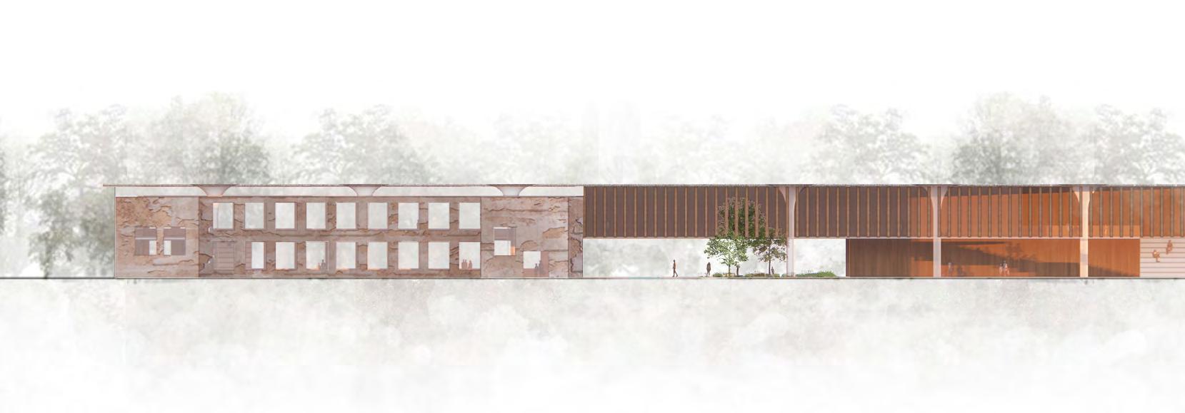
THE EXTENSION: ASIMILATION OF PATTERNS WITHOUT REPLICATION
Using several precedents of extensions of historic buildings studied different ways in which I could develop an annex for the mill that would sit beside the historic building without hindering its appearance and instead continuing its rhythm. One approach that I immidiiately discarded was the replication of an exact pattern through copies of the openings and window frames as times have changed and ornamentation in architecture is not present in the same manner.
The extension of the Carlisle Cathedral or the Saint-Francois Convent show great exampless of how extensions can fit with architecture standards of the 21st century while creating a cohesive solution for additional space by maintaining aspects such as arches or materiality without relying on replication that would look artificial and hinder its host building.


PLANNING THE EXTENSION
Extension of Carlisle Cathedral, Feilden Fowels
Saint-Francois Convent Restoration, Amelia Tavella Architectes
San Sebastiano Church Fagnano Alto, Francesca Menestò
Palazzo di Vigonovo Restoration, 3ndy Studio


Understanding the pattern that the original mill followed as well as the materiality scheme resulting from the renovation including red sandstone and CLT

ASIMILATION OF PATTERNS WITHOUT REPLICATION

Creating a simplified pattern of openings that combines the rhythm of those in the original building and its materiality, while providing an otherwise flat façade with dimension and framing

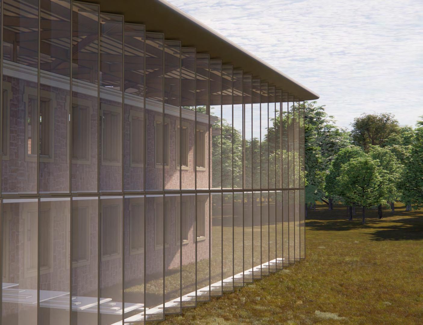
Heavily influenced by the work of AAU
on the
I followed their establishment of a pattern through the inclination and setting back of the openings of the building in order to create a way to frame an otherwise flat and simple façade. This creates an engaging façade that finds a way to create ornamentation of a sort through simplicity in lines and decorations.

Following the dimensions and materiality of the original mill façade, a rhythm and cohesion is established between both structures on its main façade, avoiding a negative visual impact and hindering of the building’s historic presence on the site.
ASSIMILATION OF PATTERN THROUGH WINDOWS


THE EXTENSION
Anastas Architects
Toulkarem Courthouse,
Original mill windows with simple frame ornamentation
New
windows for the extension with a simpler linear design
BRIDGING THE GAP


The idea of restoring the original Mill Race from the 1800s came after touring the site and learning that during the demolition work of the surrounding buildings, part of the base for ehte mill race was dug up and discovered to be in good conditions. During the same visit, we learned that the site received pretty significant flooding almost annually and that, although the Cleator Mill was not affected after the building of raised river banks, the surrounding area is, and has been an obstacle for the development of the site.
By re-digging the Mill race, a secondary stream would flow from the river right before it hits the horseshoe bank which results in the flooding of the site, alleviating the pressure on the site and further down the stream. Due to the river being cut and connected just a couple hundred meters apart, the environmental impact on the flora and fauna is almost negligible, as adviced by members of the Cumbrian Wildlife Trust
Additionally, just like back in the 19th century, the mill would be use as a source of energy. This never depleting green renewable energy would allow for the powering of the building and most of the power required for the buses and DRT minivans.


1820 2023 A mill race was built in 1820 to power Flask Mill
got
build
road
now connects the Mill with the town Park & Ride structure built in 2021 to accommodate Sellafield workers Historic Flask Mill and Kangol Mill buildings demolished periodically with the most recent demolition happening in 2021
and
covered up to
the
that
Connecting both portions of the complex, a set-back glass spanning structurre allows for horizontal moving along the top floor while the pedestrian footbridge allows for circulation through the ground floor.
Proposed masterplan for the Mill Race, traversing the building
Children sitting by and swimming in the stream’s water in the summer months
50mm CLT Louver Frame
5mm Translucent Recycled Acrylic Plate - 3mm PVC Waterproof Membrane on Aluminum Cladding Sheet - 250mm Polystyrene insulation - Glulam Grid Beam - Steel Bolt Attachment - Top Rail Encasing - Motor - Pulley rotation mechanism
- 50mm CLT Louver Frame - 5mm Translucent Recycled Acrylic Plate

100mm CLT planks - 200mm Reinforced Glulam Beam
Steel Plaque
Steel Bolts and Nuts - Galvnized Steel Screw - Washer
Pinot Pins - Pulley Rotation Mechanism
Motor
Ring Brace

The implementation of motorized louvers in a façade with permanent sun exposure is a great way to regulate the amount of glazing and the internal lighting comfort levels, as well as regulating temperatures. In the case of the building, the walls on this facade are all part of the main library, where lots of natural lighting is needed but glaring can be distracting and bothersome, so the translucent louvers provide views and natural light without glare.
The liuvers’ position within the building, across the balcony, create a double skin of sorts which allows for the reduction of the cold bridge between exterior and interior by maintaining a warm envelope. Rotational Motor
Steel Rail
Pulley Rotation Mechanism Washer Guide

Pinot Pins Steel Brackets
Translucent Recycled Acrylic Plate


Washer
- 150mm Horizontal Glulam Beam - Galvnized Steel Screw - Washer - Pinot Pins - Pulley Rotation Mechanism - Bottom Steel Rail - Steel Bracket
- 50mm CLT Louver Frame - 5mm Translucent Recycled Acrylic Plate
1 2 3 1 1 2 3
LOUVERS - 1:5 DETAILED STUDY
-
CLT
-
-
-
-
- Steel Rail
-
-
-
-
-
-
3:
2:
- BALCONY 1: TOP
Pinot Pins - Pulley Rotation Mechanism
Bottom Steel Rail
Steel Bracket
BOTTOM BASE - LOUVER
MEDIUM HINGE
HINGE - ROOF
ISOMETRIC REPRESENTATION & LOUVER SEQUENCE

ROTATIONS NO SUN : ALL LOUVERS ARE OPEN MAXIMIZING NATURAL LIGHT EVENING SUN: WINDOWS ARE BLOCKED ON THE RIGHT SIDE OPENING GRADUALLY TOWARDS THE RIGHT
In order to ensure that the library receives the appropriate amount of sunlight to keep a bright and comfortable space without glaring, and to regulate the buildings’ temperature, the louver system is equiped with a motorized rotation system that angles the louvers in pairs according to the sun position provided by sensors. This ensures that direct glaring light is avoided by blocking the sun path while allowing for natural light to flow directly through the areas which aren’t on the main path.


WINDOWS
ROOF, GUTTERS & SKYLIGHTS
BEAMS
CLEATOR MILL AND NEW EXTENSION
BALCONY AND FIRE ESCAPE STAIRS
LOUVERS
MID DAY SUN: LOUVERS ARE BLOCKED IN THE CENTRAL PORTION WHILE OPEN TOWARDS THE SIDES
LOUVER
MORNING SUN:
ARE BLOCKED ON THE LEFT SIDE, OPNEING GRADUALLY TOWARDS THE LEFT.

DRT Bus Station Education Hub New Mill Race Mill Chimney Mill Race Steps Mill Race Pedestrian Bridge Children’s Playground Road out of Complex 2 6 1 5 3 7 4 8 1 1 2 3 3 4 5 7 6 8
MASTERPLAN

Social Stairs Toilets Teachers’ Room Kindergarten Classroom Nap Room Kindergarten Entrance Exhibition Space / Lobby Main Entrance Café Café Seating Bus Station Lobby Station Toilets Bus Platform Outdoor Seating Mill Race Mill Race Bridge 2 2 2 2 6 1 10 6 5 14 1 3 9 5 7 13 3 15 11 7 4 15 4 4 8 16 12 8 16 10 14 9 13 13 13 13 13 11 15 12 12 16 15 GROUND FLOOR GENERAL ARRANGEMENT

FIRST FLOOR GENERAL ARRANGEMENT Social Stairs Toilets Reading Area Coworking Library Lounge Balcony Fire Stairs Kindergarten Entrance 2 2 2 6 6 1 1 1 5 5 5 3 3 3 7 7 7 7 4 4 4 4 8 8 8


FIRE EVACUATION STRATEGY
GROUND FLOOR
FIRST FLOOR
RESTORED CLEATOR MILL: KINDERGARTEN AND LIBRARY

EXTENSION OF CLEATOR MILL: CAFÉ, LOUNGE AND LIBRARY


THE PLAYGROUND AND RIVER PARK


THE LIBRARY THE LOUVERS

THE BUS HUB

THE
KINDERGARTEN
