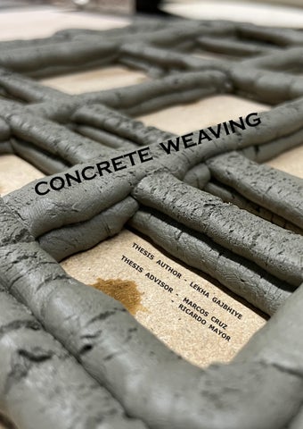
THESIS AUTHOR - LEKHA GAJBHIYE THESIS ADVISORMARCOS CRUZRICARDO MAYOR CONCRETE WEAVING

Master in Advanced Architecture ( MAA02)
Thesis Studio - C - Biom. A
Thesis Author - Lekha Gajbhiye
Thesis Advisor - Marcos Cruz & Ricardo Mayor
Institute of Advanced Architecture of Catalonia Barcelona , Spain.
Thesis presented to obtain the qualification of Master Degree from the Institute of Advanced Architecture of Catalonia
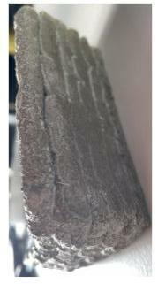
Additive Manufacturing of Concrete with pressure based extruder.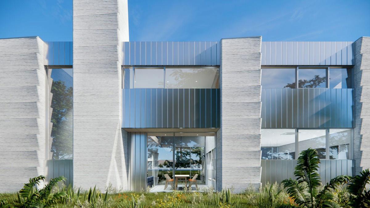 Two-story Houston home designed by Leslie Lok and Sasa Zivkovic, which features a first-of-its-kind hybrid design utilizing 3D-printed concrete.
KEYWORDS :-
- 3D Concrete Printing.
- Prefabricated Components
- Robotic Construction - Small scale
- Building Envelopes
- Environmental High Performance
- Additive Manufacturing
- Material Optimization
- Dexterity :- skill in performing tasks.
- Articulation :- clarity in the production of successive notes.
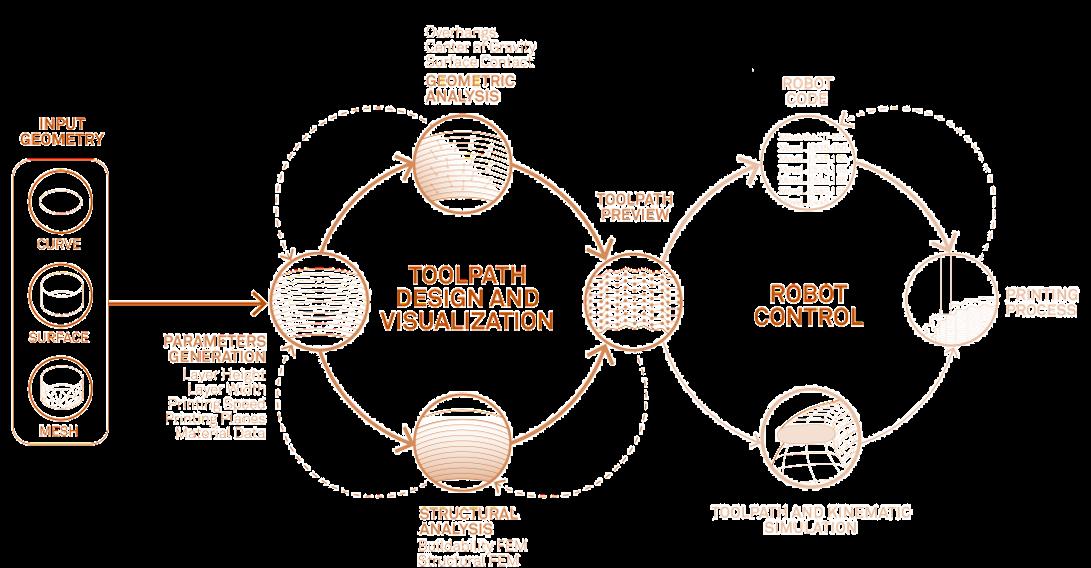
3d printing concrete is transforming construction sites worldwide by producing high-quality homes faster, better & cheaper. It seems there is enormous scope to rethink the building performance in the sense of geometry, materiality and environmental effect.
The thesis looks into material working (cementitious material ) printing in layers and searching for effective strategies for printing complex geometries and enhancing aes thetic and environmental quality. Also, look through the critical aspect of manufacturing quality and work towards a better understanding of the environmental psychological.
The project focus on advanced systems integration between radiation-based building performance design and advanced additive manufacturing, enabling the printing concrete industry to design and manufacture innovative architectural products with added value for end-users in energy savings. The goal of our project is to develop and test robotic 3D-printing systems that enable customization for high-resolution parts. Research evolves along with three main thrusts of work materials, systems, and design.
Combined with optical simulation based on finite-difference time-domain (FDTD) analysis helps to understand the role of the structure profile for different periodicities and heights to achieve enhanced light and a soothing environment. Introducing the concept of a biologically inspired design process by using different design paradigms depending on the opportunities, challenges and knowledge characteristics. Inspiring from nature to develop new design concepts and products (biologically inspired design BID) can be approached using different paradigms concepts such as solution-driv en BID, biomimicry and bio-replication.
Further research examined the effects of different wall textures on the observer’s perception of spaciousness in indoor space, the influence of wall texture changes in dif ferent room sizes, and how the associational meaning of texture affects the degree of influence of wall texture on the spaciousness of indoor space.
Emphasize the functional (behaviour) role of morphology for environmental adap tation, where distinct morphologies, corresponding processes, their underlying mecha nisms, and potential applications to buildings are distinguished. the key objective was to deliver a fine print resolution as a result of high production speed, process stability and robustness.
Therefore, the research is to investigate how to design space for the texture typology that could be enhanced by 3DCP.
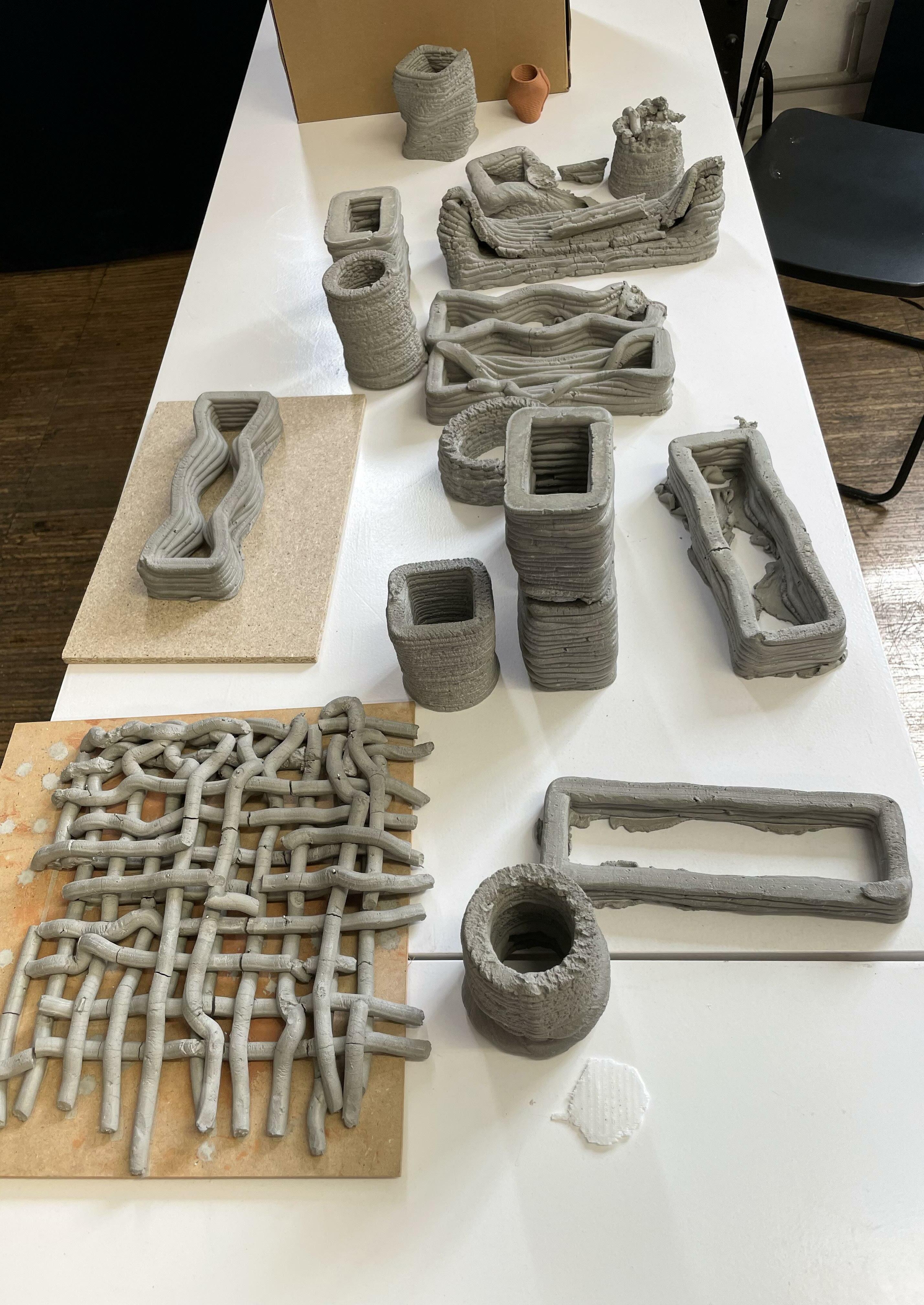
The goal of this research is to explore the 3d printing techniques and material be haviour with the pressure-based extruding system to create 3d printed panels in order to bring awareness for robotic construction in the existing building and their environmental effect. The key aspects of this investigation are material experimentation and physical prototype through digital fabrication. The whole material research and producing physical prototypes have been conducted in a controlled laboratory environment with care and precision taken care to ensure accurate results. Experiments discussed in the further chapters are performed by the author itself.
Initially, the research was focused on developing a strategy to create a textured pattern for the concrete 3D printed structure, so as to provide insulation with the ther mal and radiation effect within the structure. Whereas another purpose is to make the strategy simple but effective which as result can be used in the mass housing concept of 3d structures to give them their own characteristics. The following research focuses on how to use robotic fabrication to produce small elements which will be implemented into large-scale structures with environmental studies.
Many 3D printed constructions made with different concrete mixtures and shapes can be found in the available literature. Despite the fact that 3D printing of concrete build ings is growing fast, and whole 3D printed houses are now widespread in the world, there is still limited application and experimentation of 3D printing for concrete components prefabrication. However, prefabrication through 3D printing has enormous potential, es pecially in a long-term vision where the combination with robotic construction processes can lead to a fully automated and sustainable building process. Indeed, recent research ers have demonstrated the interest of the construction sector in the combination between digital concrete and prefabrication
thesis advisor, Marcos Cruz for his guidance, dedication and continuous inspiration throughtout this thesis project. His remarks were vital to the outcome of this thesis and will always be deeply appreciated.
His vital critis were constructive and positive, even during online session and constantly motivating to create a positive attitude towards your works.
Additional, I would like to thank you Ricardo Mayor for his support for digital fabrication and encourgemnet throughtout the project.
I would also like to thank : Mathilde Marengo for her continuous advice and theoretical support which laid foundation for the thesis to be built upon and Nikol Kirova for her sup port in terms of organizing and managing everything from behind the scenes, as well as one of the student Aniket Sonawane for constant fabrication assistance.
Lastly I would like to thank my family and some friends for their support and encourage ment throughout the two years as a student at IAAC.
INDEX - Abstract - Preface - Acknowledgments - Index - Introduction
3D Printing - A Viable Solution
Thesis Statement
Aims & MethodologyObjectives
- State of Arts ( Concrete 3D Printing ) Concrete 3D Printed Panel
- Concrete Material & Technique Research
Characterstics and Properties
Initial Manual Exploration
Additive Manufacturing (Concrete Robotic Printing) Extrusion Printing Strategies & Parameters

StrategiesCatalogue Conclusion
Outcomes and Solution
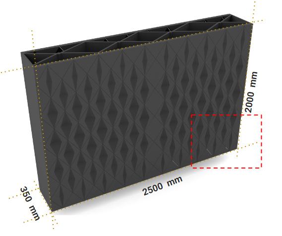
Design Proposal (Facade System)
Concept Development for Facade Panels
Facade Process Catalogue
Fabrication
Conclusion - Bibliography
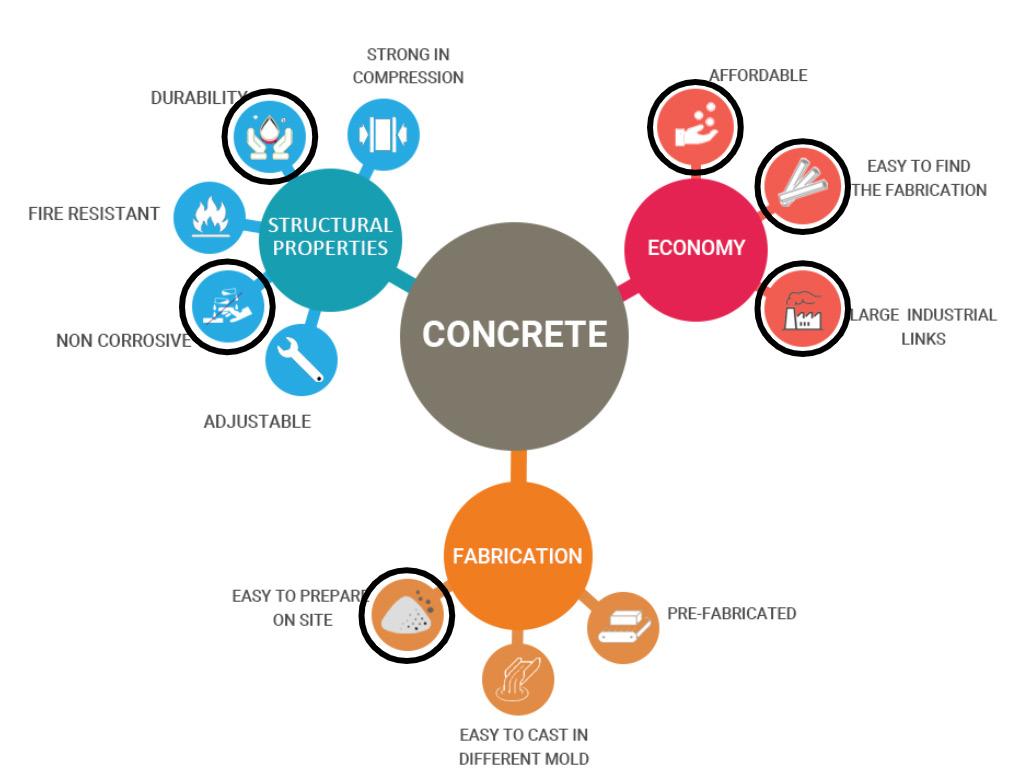
Concrete can be defined as the composite material composed of the binding me dium such as the mixture of cement, water, and different fine and coarse aggregates. Many people do consider cement as concrete, but cement is just a part of concrete. Concrete structures that have been built around the world are subject to a wide range of different conditions of use and acquaintance with environmental conditions comprising erosion, weather, and pollution.
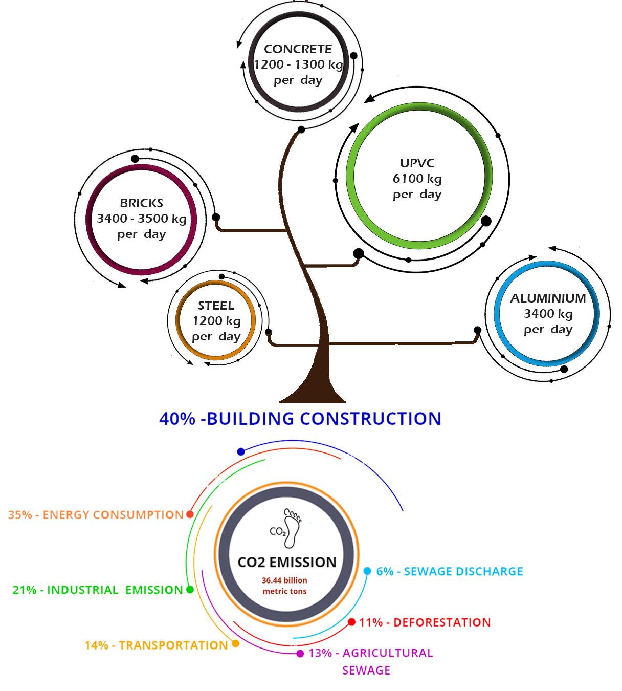
All environmental conditions found concrete as the long-lasting and the best bind ing material. Besides whatever the conditions might be, concrete is expected to provide satisfactory performance for the wholeness of their service life with very little care. It’s the highest consumed product on earth besides water. As a material that creates the majority of the structures, houses, world’s bridges, roads, dams, and construction con crete releases an extreme amount of CO2 each year.
Cement business itself emits more than 3-4 billion tons of carbon each year, so in order for us to go forward with this process, we would need a lot of money to care for the amount of carbon cement industries produce. This is a very high number for companies to take on, especially lower-income ones. Carbon sequestration could be a possibility for the future, but as of now it most likely will not be done.
The concrete industry struggles with a large carbon footprint but there are many solutions. The only struggle is depending on the consumers to choose the groups who put our climate as a priority. Information and listed solutions need to be put in the spot light in order to improve and create a cleaner world.
Everyone is aware of Concrete and its use, but its production is one of the main reason for carbon
situation it is highly important to focus on the implementation of new technology and construction techniques, especially in countries and regions with the highest cement production.
About the issue every year 36.44 billion carbon emissions occur, of which almost 40% are produced by the construction industry. In the traditional construction process, a large amount of material is wasted which lead to environmental effect. So to eliminate the need for a framework and thus mitigate excessive wastage of material 3d Printing concept was introduced to the market. Which work on 3 main concepts: i) Cost & Time effective; ii) Mass Structure Construction & iii) Net Zero Concept.
The construction industry produces buildings and infrastructure. These construction works are typically immobile and customised and must meet many criteria to provide value to modern society: structural safety, durability, serviceability, aesthetics and inte gration, environmental sustainability and construction efficiency. However, the construc tion industry has a considerable environmental impact, with reinforced concrete as its primary driver due to its extensive use, and will be facing an ever-increasing responsi bility to tackle climate neutrality in the upcoming years.
One of the viable solutions the construction market is adapting is the concept of digital fabrication and robotic construction which can also be called additive manufactur ing construction. Digital fabrication with concrete is a young yet already broad discipline that brings about the potential for the necessary reduction of the environmental impact and further industrialisation of the construction industry while being compatible with the multifaceted requirements for construction works. The current development of the built environment leads to the need of replacement of some old existing buildings with new ones, which leads to the high demand for concrete. Whereas digitally driven structure working - offer benefits of productivity which is the reduction of intermediate stages re quired in fabrication and material deposition.
Concrete 3D Printing is set to reshape the Construction Industry Scene

According to the market study, the global 3D printing market is estimated to grow from USD 12.6 billion in 2021 to USD 34.8 billion by 2026, at a CAGR of 22.5%. Ease in development of customized products, reduced manufacturing cost and downtime, in creased work floor productivity and increasing government investments in 3D printing projects are some of the key factors driving the growth of the 3D printing market.
The types of automation and robotic technologies for construction can be grouped into four general categories: (1) Off-site prefabrication systems, (2) On-site automated and robotic systems, (3) Drones and autonomous vehicles, and (4) Exoskeletons.
Current DFC ( Digital Fabrication Construction ) of concrete applications explicitly targeting the mass building market, such as 3D printed houses, essentially replace lightly loaded masonry walls with unreinforced 3D concrete printed walls or employ DFC as lost formwork instead of relying on traditional methods. While such applications of DFC facil itate the seamless digital design-to-construction process and may be more time-efficient than conventional walls built by a mason, their environmental impact with currently used concrete mixes is even higher than that of conventional construction. Most DFC processes currently rely on concrete mixes with small aggregates and high clinker contents, result ing in performance beyond the requirements for lightly loaded walls.
Being a cost-effective and wasteage-reducing method, robotic construction needs some detailed research regarding upcoming urban challenges. Some of the research is targeting small element production, which can also be used in existing structures to un derstand various categories of robotic construction. With the potential to transform pro ductivity, reduce waste, increase choice and enable the construction of a wide range of sustainable structures, robots represent the future of the global building industry.

Governments and construction companies are bound to continue seeking new technologies to make building processes safer, more cost-efficient and sustainable.

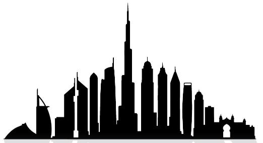
Many competition and tender is getting proposed to adopt 3d Printing techniques. Such as in May 2018, the Dubai Municipality mandated that all its new buildings should be at least 25% 3D printed by 2025.
3d printing concrete is transforming construction sites worldwide by producing high-quality homes faster, better & cheaper. There is a huge scope to rethink the building performance in the sense of geometry, materiality and environmental effect. This thesis looks into material working (cementitious material ) printing in layers and searching for effective strategies for printing complex geometries and enhancing aesthet ic and environmental quality.
Also, looking through the critical aspect of manufacturing quality and working towards a better understanding of the environmental analysis, later helps to construct a technique which allows digital design fabrication method and assembly with complex geometry in a more sustainable way.
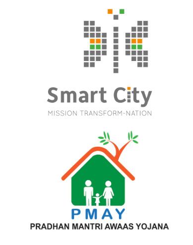
Tender by the local state govern ment to build mass (200) houses using 3D concrete printing tech nology is focused on to affordable housing sector. (like in California and Africa)
The Indian government bodies facilitat ing affordable housing under the mis sion “PMAY-Housing for all” & “Smart City” have been putting efforts to at tract, identify, and incubate new tech nology from across the globe to build affordable houses.
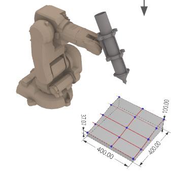
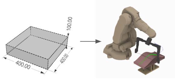
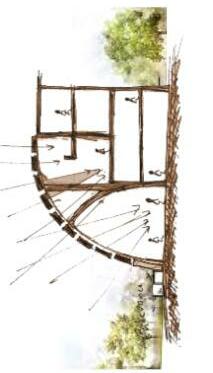
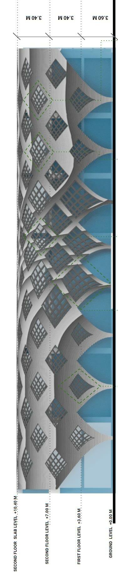
Study the structure on basis of SUNLIGHT & radiation analysis, and propose a facade system by using a different form of texture patterns and openings in the wall.
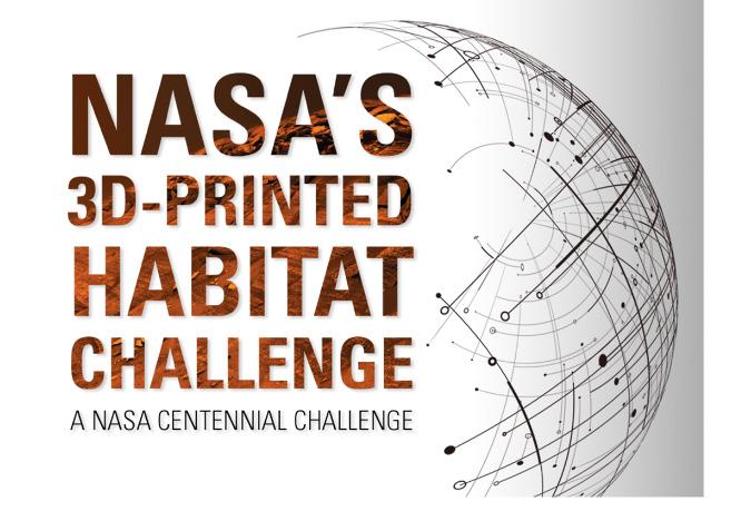
“3D Printed Habitat Challenge” or ganized by NASA. The aim was to promote the evolution of new tech that could additively manufacture a habitat using local materials.
Countries like Dubai & China mandated that all its new buildings should be at least 25% 3D printed by 2025.
The first section introduces the framework of ongoing projects and research explored with concrete construction to get an optimised output with controlled construc tion methods. The main focus of this section is to get educated about various category concrete fabrication is been explored. The set of example projects or research which are explained further not only focuses on construction techniques but also a detailed study of the material mixture, environmental analysis, cantilevers & small element production.
The second section will mainly be focusing on robotic fabrication and producing physical prototypes. A set of methodical experiments were conducted and recorded, with the aim of creating a material consistency with certain qualities, without any additives or
explores additive manufacturing of the material with the concept of non-planer printing and also creates a catalogue to explore the possibilities to create small structure elements which will further aggregate and form one complete strong and stable prototype.
Finally, the conclusion with the conceptual design proposal, general overview and future developments in the field of research is presented as the closing part of the re search.
There are relatively many architectural projects that include the use of concrete as a primary material. Though, the material is know worldwide, but still their are research and developemnts are going into to develop this material cheaper and more sustainable for constuction purpose. The projects that were studied are seen as a starting point in understanding the opportunities and lim itations that this common material could become. However, the future visionary on how construction robots can transform the concrete building construction sector is still not solid nor well structured.
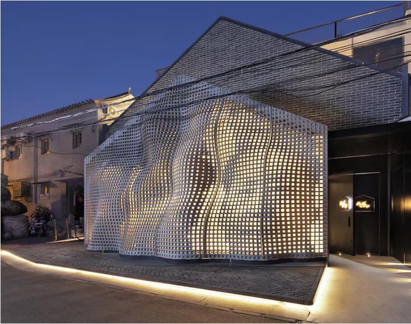
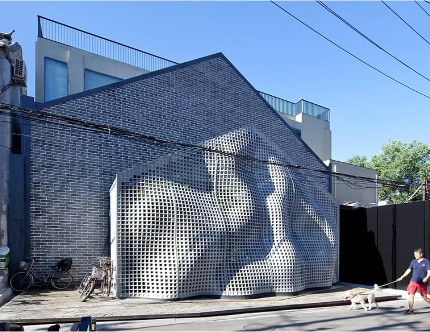
MaoHaus is an experimental façade piece exploring historical context, material potentials, novel fabrication and performative qualities within architec ture. The exterior fluidity is expressed through the conventionally rigid mate rial of concrete questioning inherent perceptions of materiality through formal expression. The work is located in a Hutong alley in central Beijing adjacent to The People’s Art House Print Shop, this workshop was once one of the primary producers of the Chairman’s now iconic image.
The structure of the façade leverages the material properties of ultra-high performance concrete to create novel architectural form. Each panel is cast as a single unit from large CNC milled molds. Computation ally generated through fluid-dynamics algorithms, the curvature of the thin porous surface serves to more efficiently carry the loads of the structure to the
seeks to explore various elements of deign within a singular expression. Looking to new material innovation the façade pushes the limits of what may be achieved from seemingly conventional architectural materials. Seeking a multifaceted design, MaoHaus exists as a synthesis of material prop erties, customized computational tooling and generation with historical refer ence, context and expression.
Image ( page 22, TOP)
- Digital Fabricated Façade
- Fabrication and Installation
- Day Effect on Facade
Image ( page 22, BOTTOM)
- Digital Fabricated Façade - Fabrication and Installation
- Day Effect on Facade
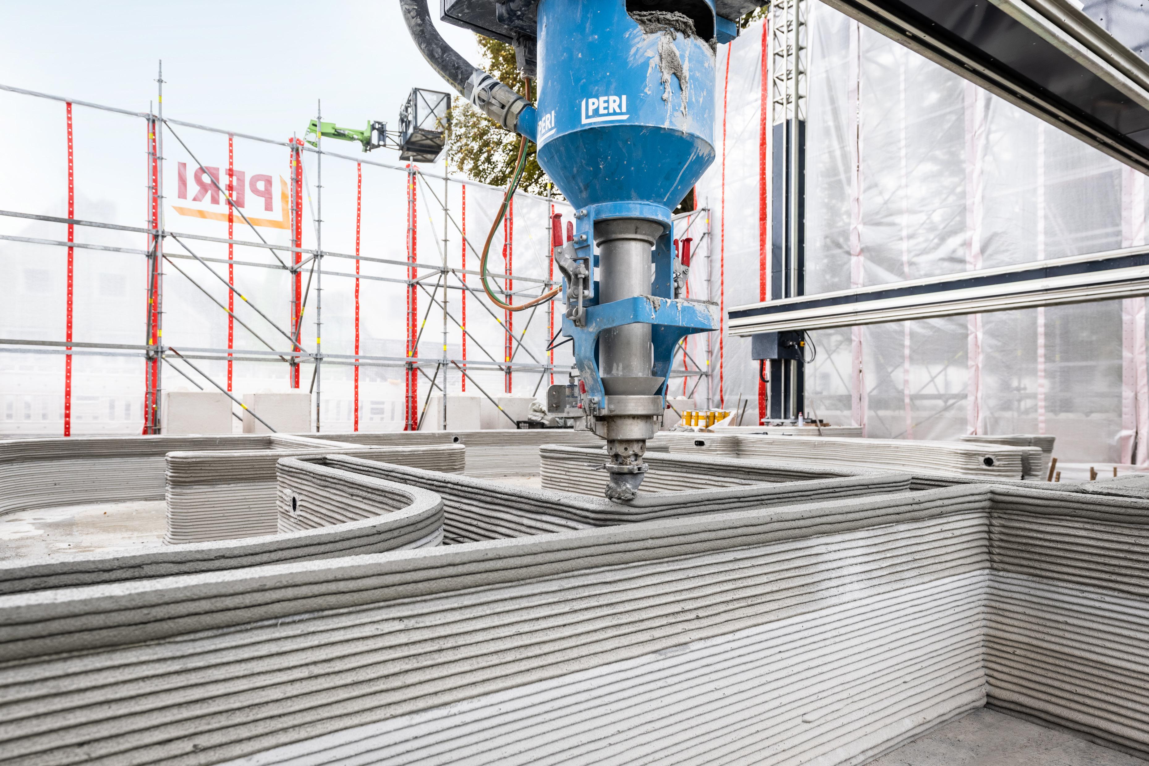
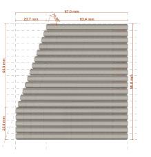
The largest 3D printed concrete façade in the world has been completed at the new Dubai headquarters of BESIX. Main aim was to bring a new dimen sion to concrete printing. BESIX 3D invested in the development of its own in-house production facility for 3D Concrete Printing in July 2018. It consists of two buildings with a combined area of 640m2 that required 582 custom-made 3DCP panels. All the panels had to be completed quickly, and on average each panel took 11 minutes to print. World’s largest 3D-printed concrete facade was created with the help of a KUKA robot. Panel dIscretization on the basis of com pressive strength & performance base.
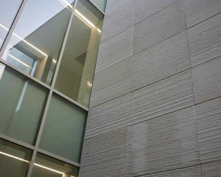
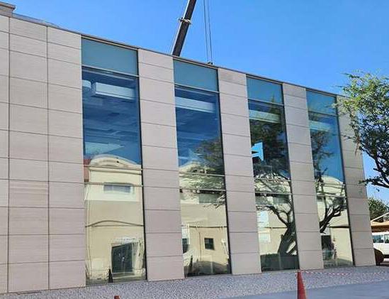
Image ( page 24, TOP)
- Digital Fabricated Façade - Exterior View
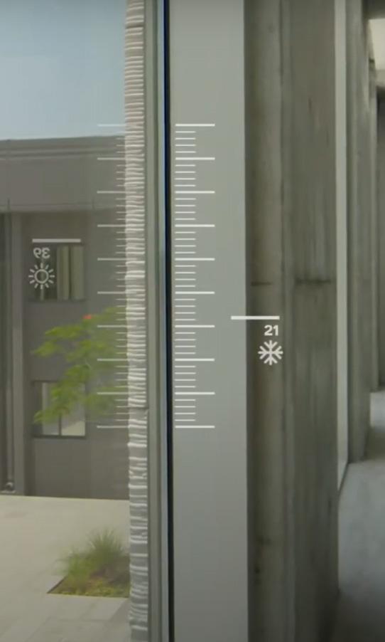
Image ( page 24, BOTTOM LEFT)
- Digital Fabricated Façade
- Temperature Difference
Image ( page 25, BOTTOM)
- Digital Fabricated Façade - Interior View
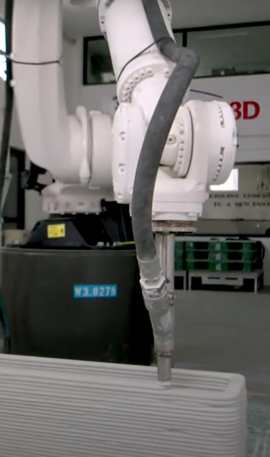
Image ( page 24, BOTTOM RIGHT)
- Digital Fabricated Façade
- Robotic Printing
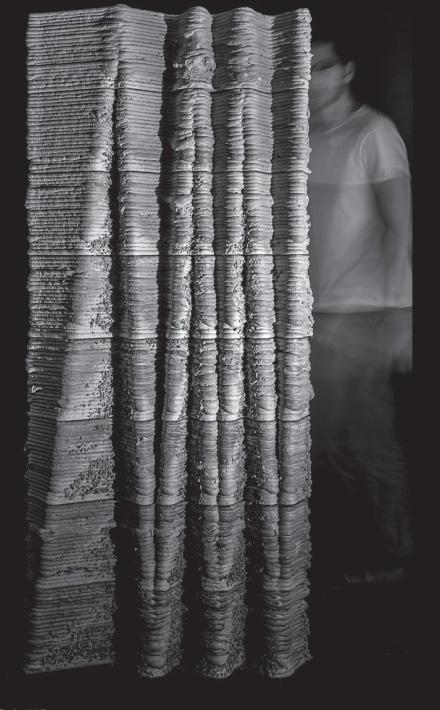
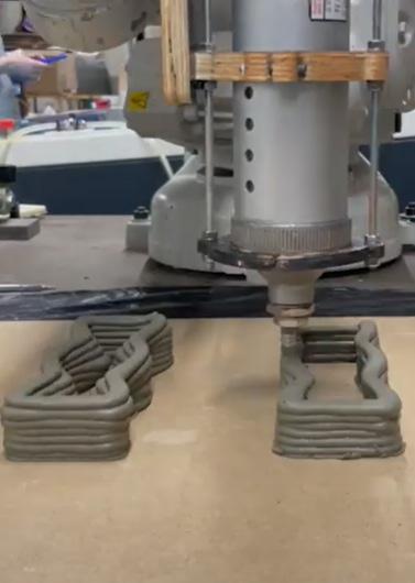
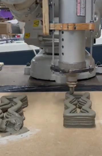
The research was explored by the students of Harvard Graduate School of Design in collaboration with Heamin Kim and Jared Friedman. Their main objec tives was to explore what alternative formal opportunities that may arise when challenging these assumptions concerning additive manufacturing. Here, clay is used for their research exploration.
The Standard definitions and models of additive manufacturing often as sume a layer-by-layer deposition of a material onto a flat surface. Prototypes incorporate techniques such as weaving as a means of fabricating panels that celebrate the inherent nature of the coil itself. The woven patterns are designed to incorporate both assembly logics and performance qualities such as light permeability across a façade component. This research works to resolve the seemingly conflicting nature between the inherent mutability of the clay material and the high level of control granted by robotic fabrication pro cesses.
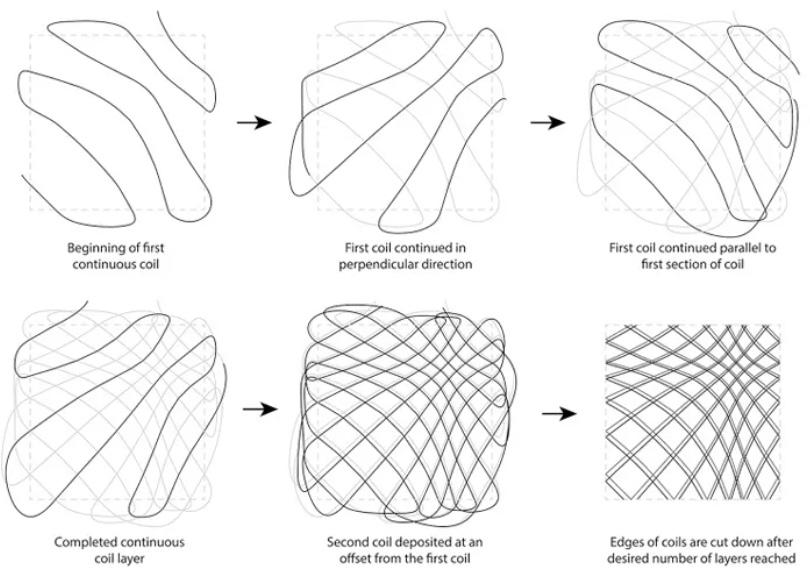
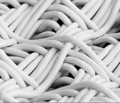
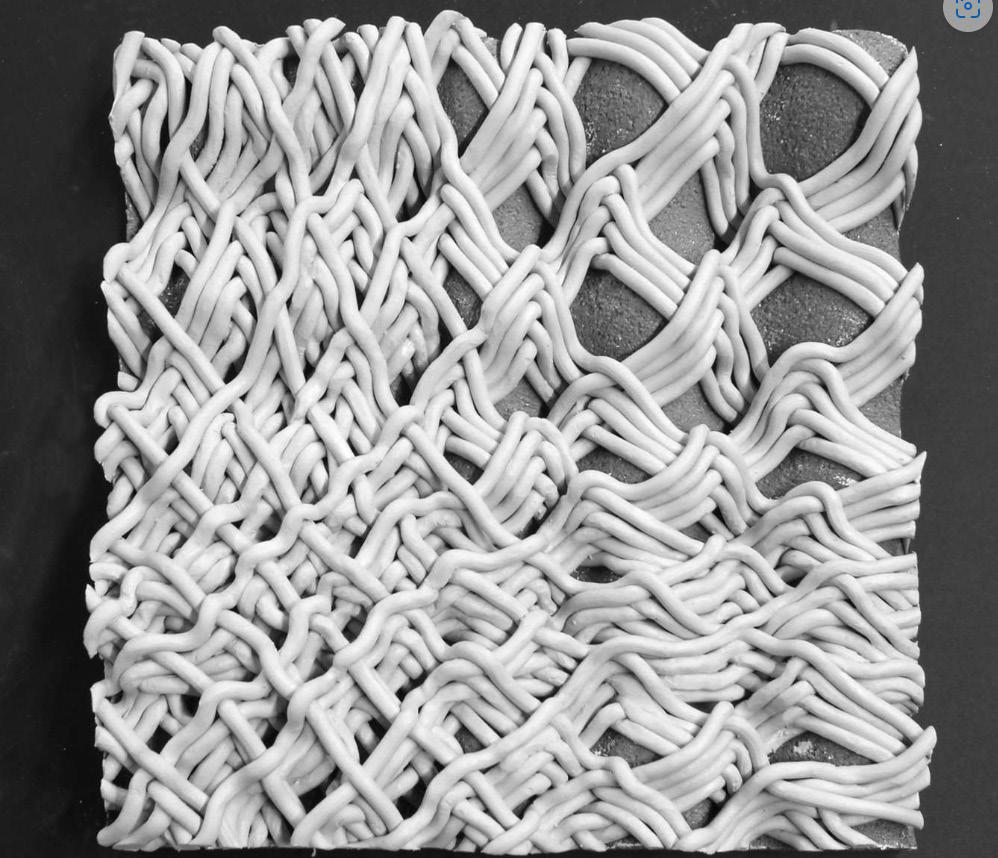
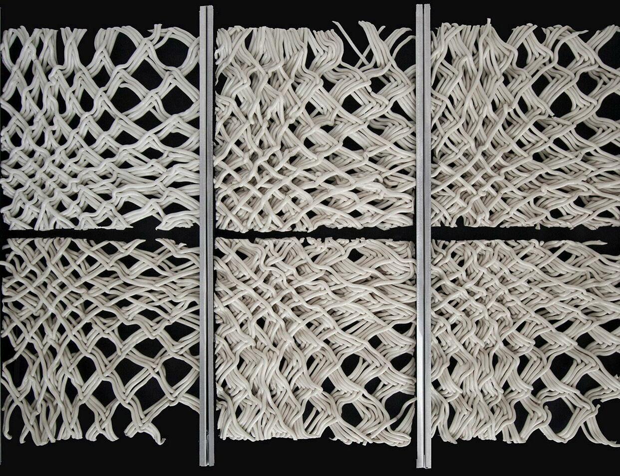
Image - a ( page 26)
- Manual Fabricated Panel
Image - c & d ( page 26)
- Robotic
Image - b ( page 26)
- Form Base Support for both manual and robotic fabrication
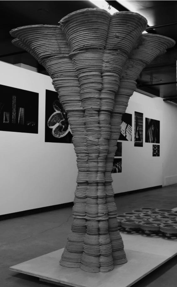
Workflow for Robotic FabricationThe A New Robotic Brutalism – Additive Architectural Elements project in vestigates prototypical methods for 3D printing at the building component scale in ground-up layered assemblies. Research aims to develop architectural strat egies for use in current industrial scale 3D printing processes - the assumption being that technology will eventually evolve to include multi-material printing, non-layered printing, or printing on site among others.
Brutalism is most intriguing when bottom-up material processes meet topdown expressive decisions made by the architect: when a symbiosis between material and method of construction facilitates specific architectural character istics such as fluidity, cantilevers, and texture, as well as accommodates the architect’s willful design expression in the overall building assembly.
Strategies deployed in the manipulation of form are the modification of printing direction (printing upside-down or printing in section) to overcome printer deficiencies, g-code manipulation for smart material deposit, or alter ations of geometries for structural reasons related to the fabrication process.
Further focusing on the technical advancement of 3D printing technology, this project operates consciously within the status-quo, researching a paradigm-shift that has already occurred but never fully and consequentially been explored architecturally: the 3D printing of buildings with concrete. Rather than drastically altering the process (stopping the machine to insert a beam), we believe that shortcomings become opportunities for design: as the printer can incrementally cantilever, one possible logical consequence is for the window to become a triangular corbelled arch.
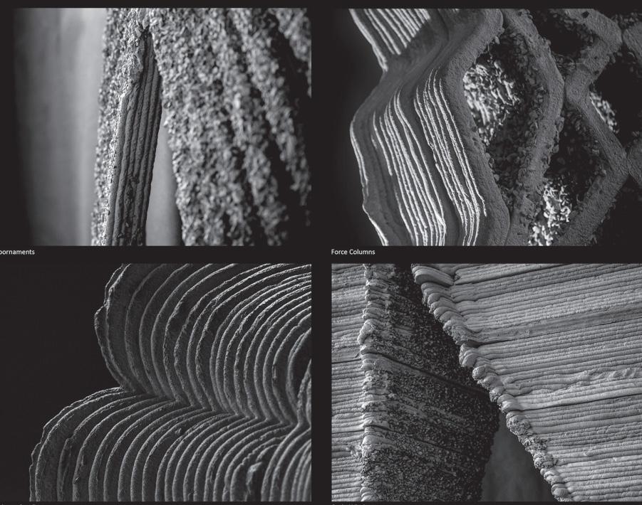
Image - a ( page 28)
- Robotic Fabricated
- Doornaments
Image - d ( page 28)
- Robotic Fabricated
- Corb Window
Image - b ( page 28)
- Robotic Fabricated
- Force Column
Image - e ( page 28)
- Robotic Fabricated
- Smart Pocha Wall
Image - c ( page 28)
- Robotic Fabricated - Column Cantilever
Image - f ( page 28)
- Robotic Fabricated - Column Brutalism
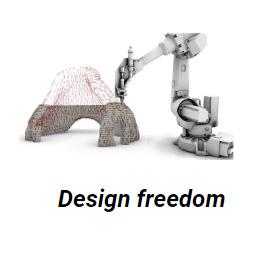
Additive manufacturing (AM) technology is currently being investigated as a pos sible construction method for future buildings. Additive Manufacturing methods have advantages over other production processes, such as great freedom of form, shape complexity, scale and material use. Different manufacturing processes demand appropriate materials processing adjustments. Concrete materials that have versatility in process ing, including normal mixing and casting in the construction industry; spraying or socalled shotcrete application in soil stabilization for mining or construction excavations, extrusion in pre-casting factories for structural elements intended for the construction industry; and spinning manufacturing processes for concrete pipes. Recent innovation in 3D printing for construction demands yet another adaption of the mixed design and manufacturing process.
Additive manufacturing method has been used extensively in the construction indus try in plants for the pre-fabrication of structural elements varying from small decorative elements to large slab structural elements. Note, however, that the fast setting ability of the concrete mix also creates issues when pausing the printing process. Printing cannot be paused for more than a few minutes, or else the concrete within the hose and mix er–pump will start to set and create a blockage within the system, potentially damaging the hardware.
Reduction of construction costs by eliminating formwork.
Enabling the potential of multifunctionality for structural/architec tural elements by taking advantage of complex geometry.
Digitally controlled additive manufacturing method which can build architectural and structural components without formwork, unlike conventional concrete construction methods.
Robustness and sustainability, advanced concrete materials (ACM) and the use of waste streams as ingredient materials have been proposed for 3D concrete printing.
Produces components directly from a digital design file and prints the special raw material layer by layer.
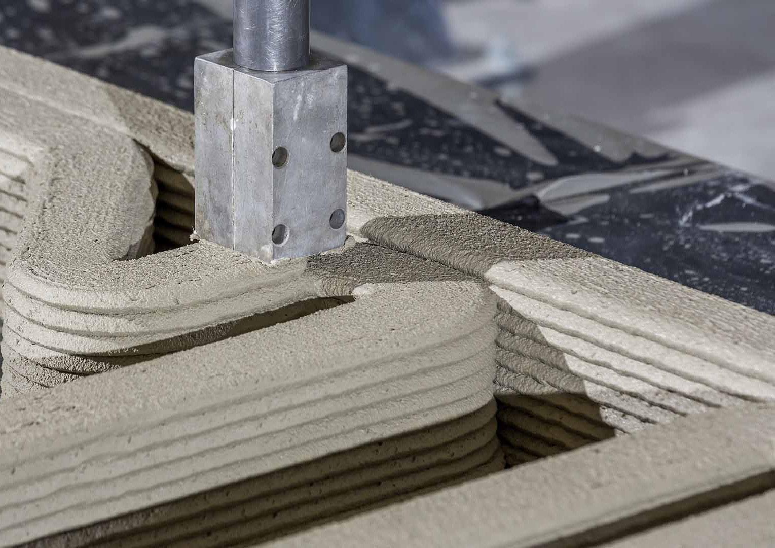
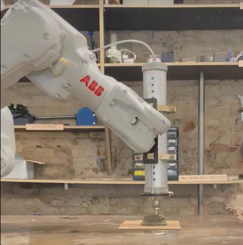
The preparation of the robotic arm could take up to one hour. In the next step, the con struction of the house walls starts, and the robotic arm lays the wet mix of concrete layer by layer according to the pre-determined path. Reinforcement also takes place during the construction phase, which includes adding steel components for structural tension.
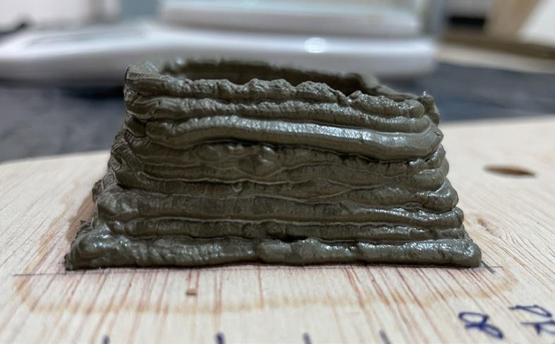
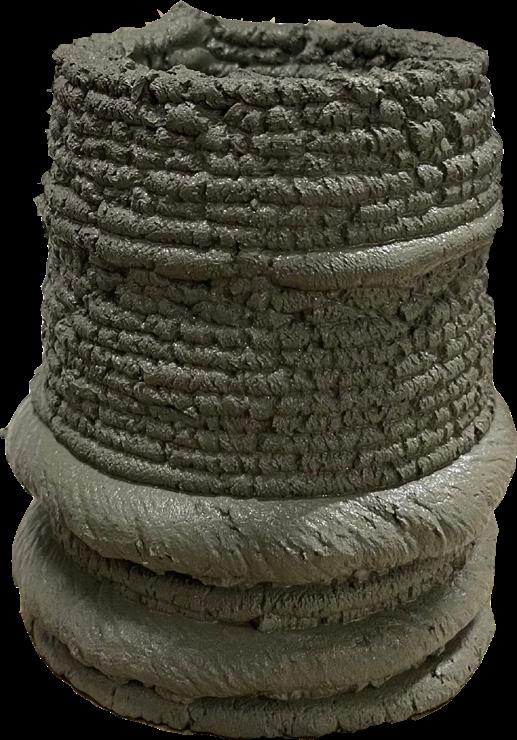
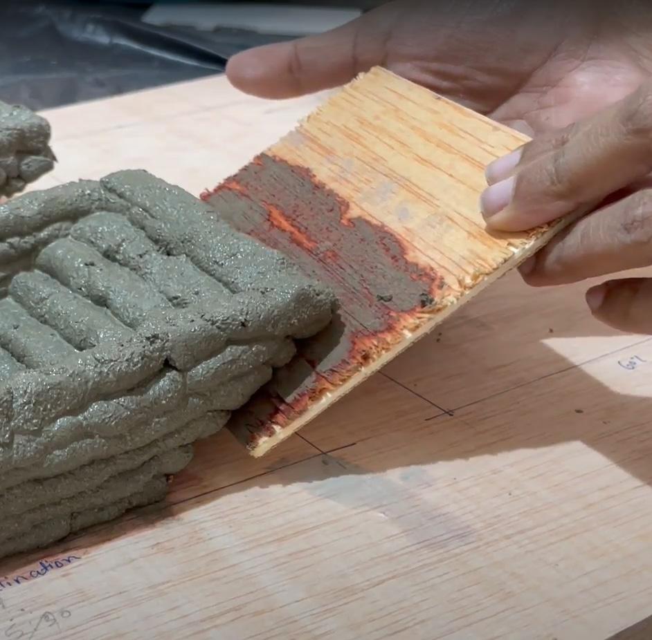
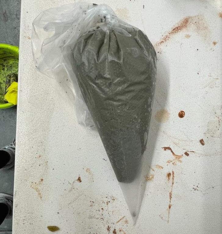
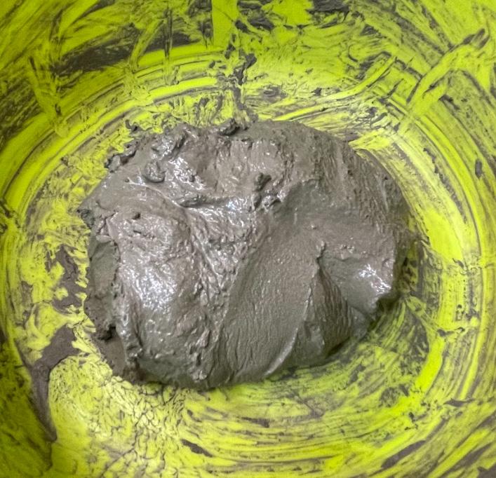
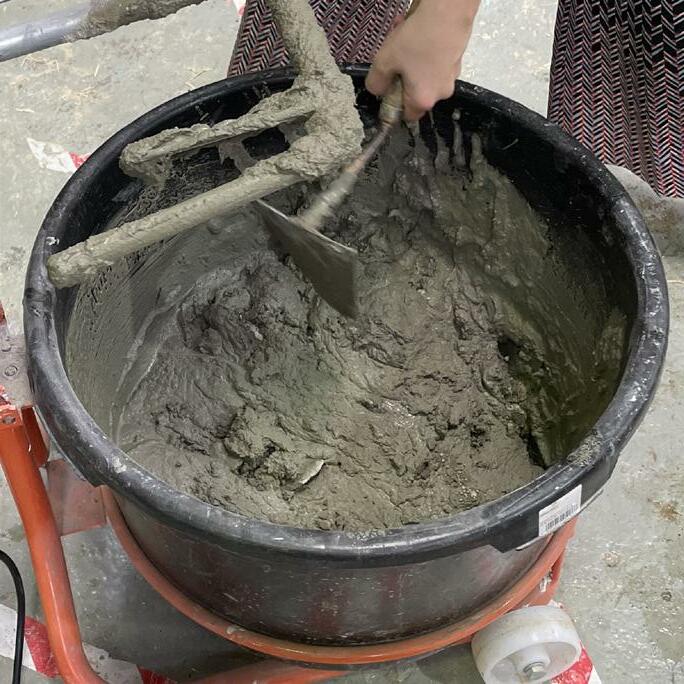
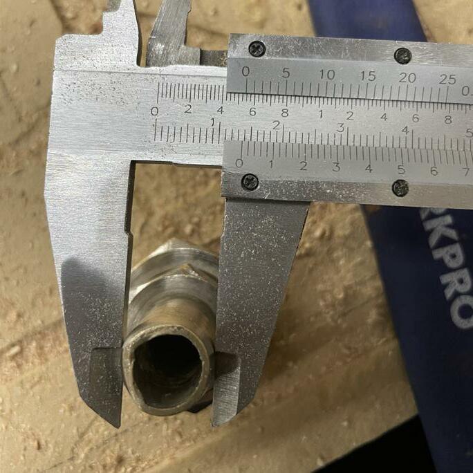
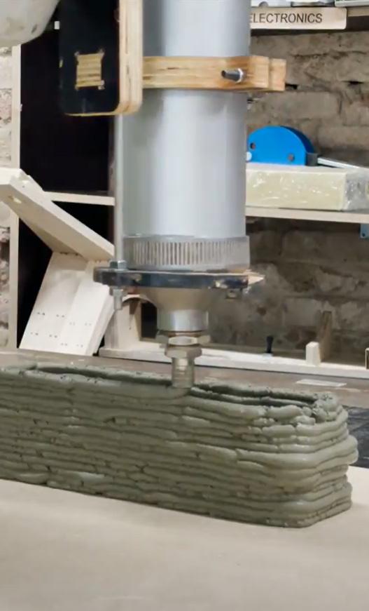
Before going directly towards robotic fabrication, the initial process was to un derstand the water-cement ratio, different material compositions & how the material behaves under a pressure-based extruding system. Initial experiments were performed manually to get data based to regarding material viscosity, water content and changes in material composition with time.
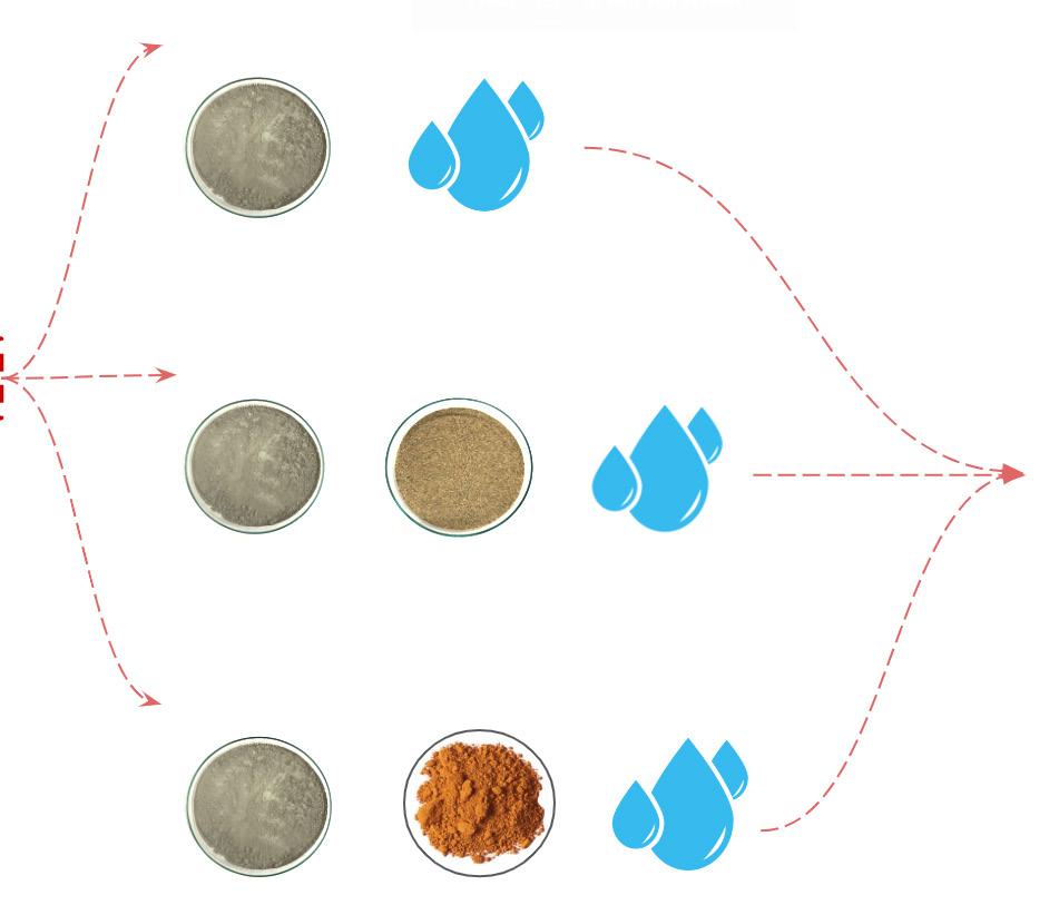
General material exploration was conducted with 3 sets of material and mixing ratios. As the extruding system was a pressure-based system the material consistency should be like extruded clay ( bit paste-like material ). Parameters like shrinkage, vis cosity, cantilever & curing were recorded for further exploration.
•
•
•
•
•
•
•
•
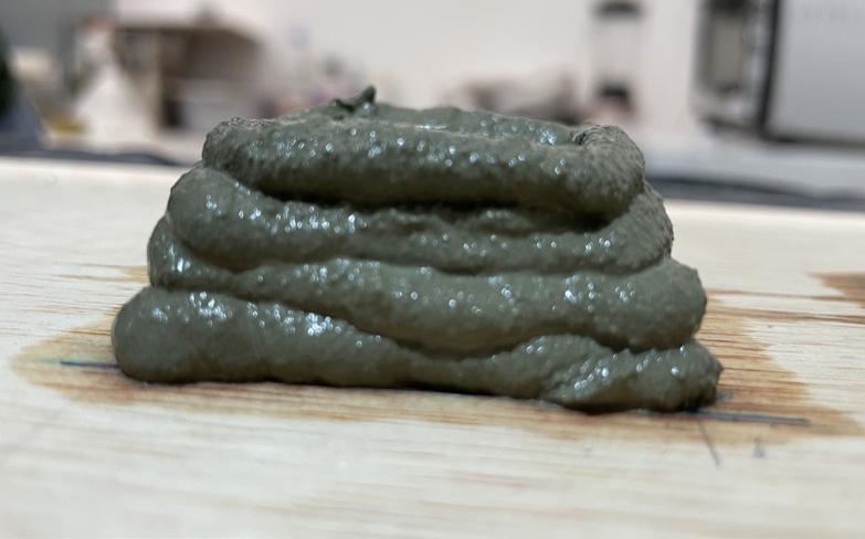
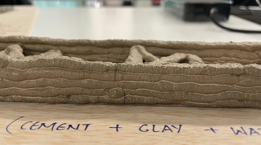
In conclusion, the prototype with the mixture of cement- water and mixture with clay were a bit fragile. Whereas, prototypes with sand were a bit strong but tends to crack as the water content was excess.
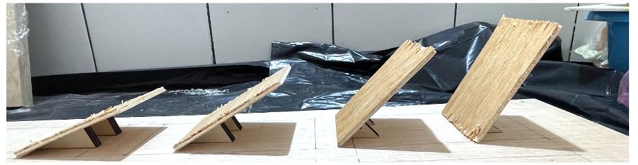
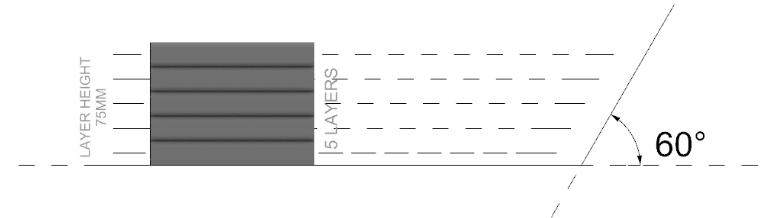
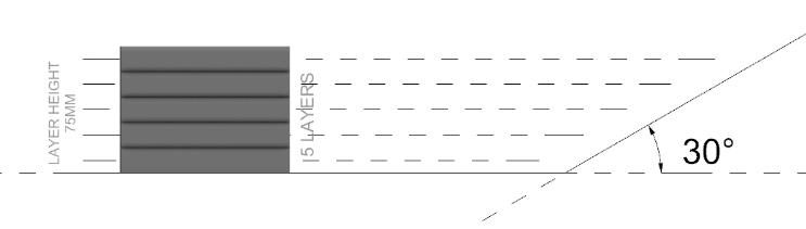
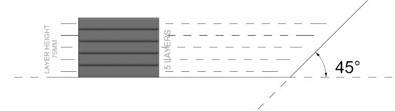
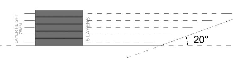
Another exploration step is to understand the material behaviour while printing in inclination. As per some research papers, the maximum angle achieved is 60O with gravel support or some recyclable material, so in this process wooden thin base is used as a support system and the angles explored were 20, 30, 45 & 60 degrees. During the process, the same material ratio mixture is used as mentioned above but the nozzle thickness changes from 10mm to 15 mm.
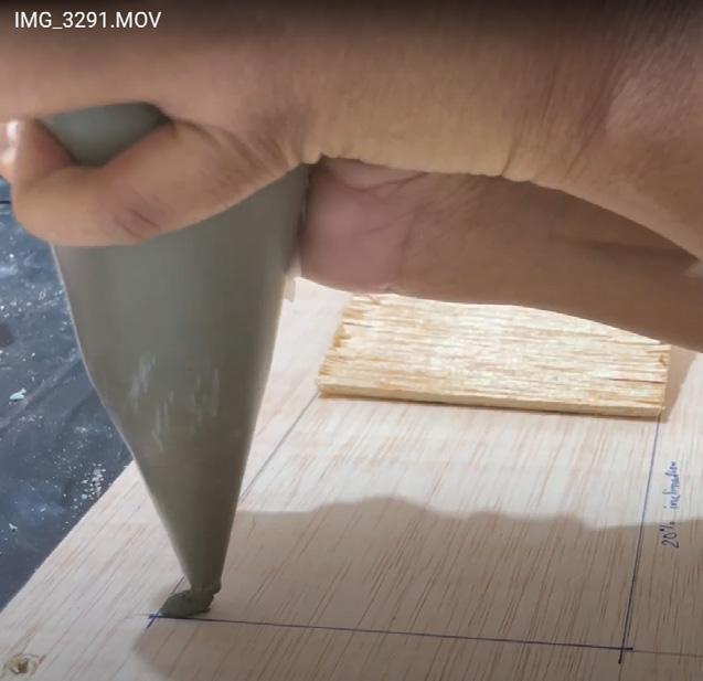
As the support are removable, those were removed after 2 hours of printing. The main purpose of the step is to understand how the material behaves when the support is removed after a certain duration and which category of material mixture collapse or sagging occurs.
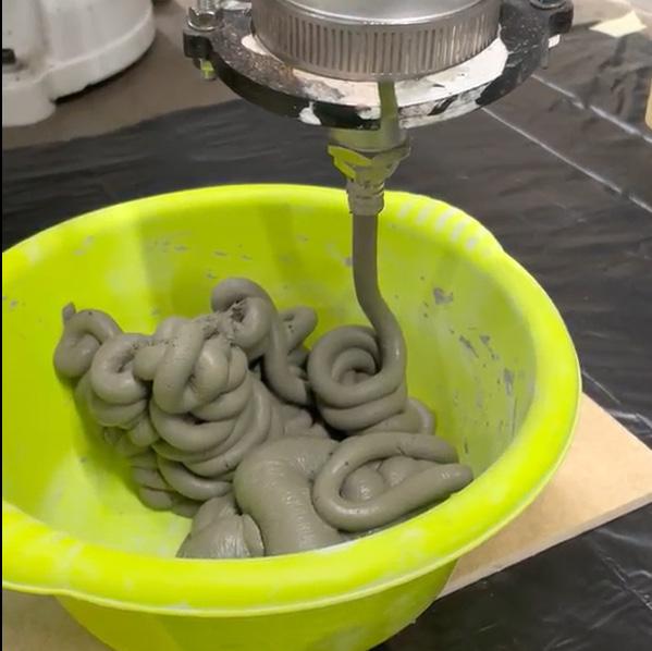
 Manual Extruder

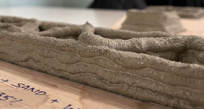
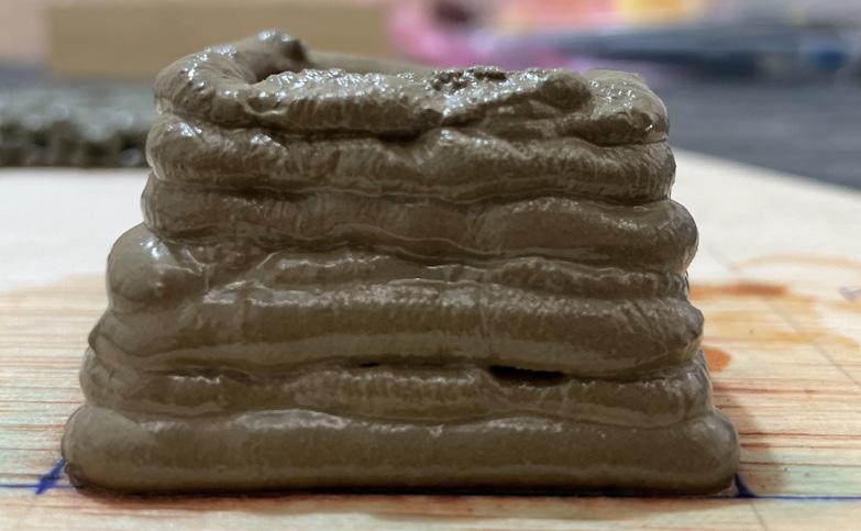
In the third exploration, the mixture contain some grams of sand just to reinforce the mixture, but the prototype was a bit fragile. Prototypes were not cured enough to withstand without the support after 2 - 3 hours. Also, the mixture was a bit greasy after some course of minutes and was difficult to get even layers and were tend to collapse while printing.
• Water Ratio should be between 20% - 25 % of the whole mixture.
• Sand ratio should be between 15% - 20%, for non-fagile output.
• 40o & 60o angle is preferred for further explo ration. ( with reinforcement )
• Prototypes without sand tend to crack after a course of time
• Prototypes with clay mixture tend to crack after a course of time
• The preferred time to remove support was - 2-3 hours.
• The whole process was done without any addi tives for reinforcement.
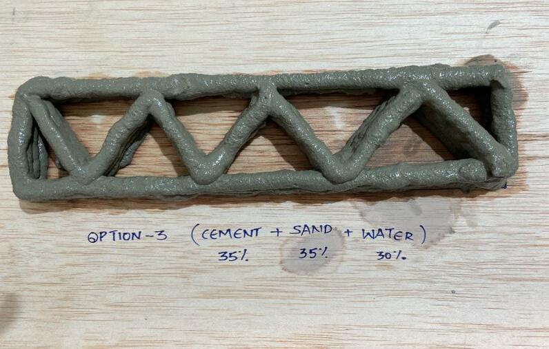
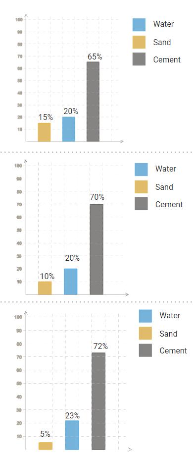
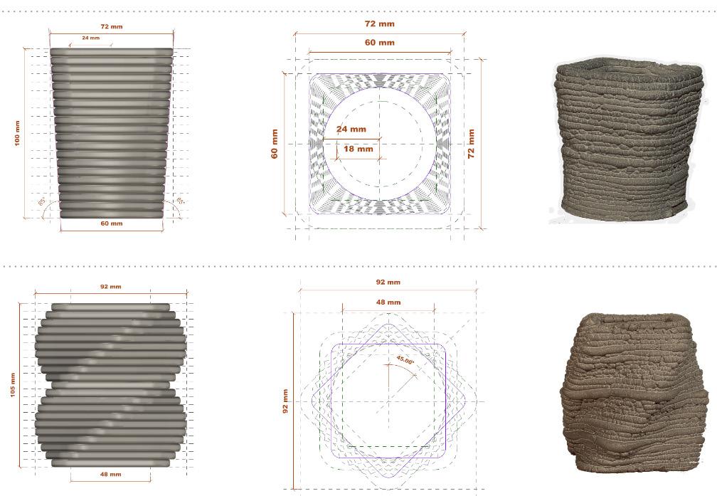
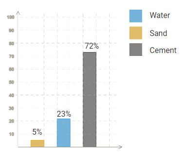
OPTION - 3 ( CEMENT + SAND + CLAY + WATER) ( Portland Cement - 350gm , Sand - 50gm , Clay - 20gm & Water Ratio - 25%) Layer Height - 7.5mm )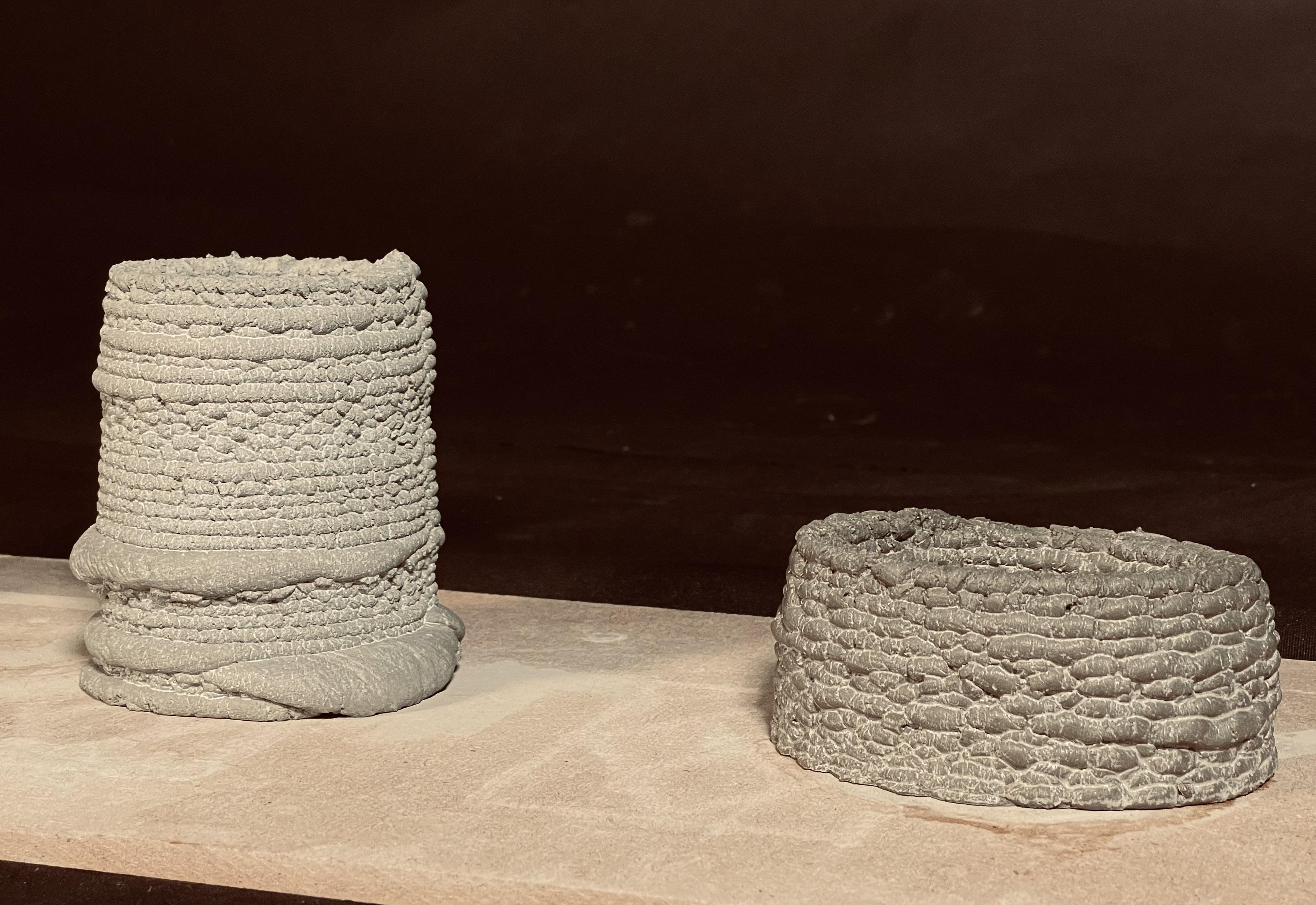
3DP is widely used in several industries, its application in architectural fields is still in the preliminary conceptual stage. There are no standardized building principles or examples, which is one of the challenges facing 3DP. Currently, there are numerous ma terials, equipment, and processes, but no clear requirements for materials, processes, calibration, tests, and document format standards.
Moreover, the main obstacles to the introduction of robotics within the building construction industry are the variability of the construction processes and the complex conditions of the construction environment. Many building construction activities have the potential to be executed by implementing robotic technologies techniques. However, adapting new technologies necessitates several special properties of high payload, reli ability, and wide workspace to be achieved.
Concrete is the second most consumed substance after water, with around 10 bil lion tonnes of concrete manufactured globally in every year. Consequently, concrete has been the focus of several investigations into robotically fabricated, geometrically com plex, non-standard loadbearing constructions
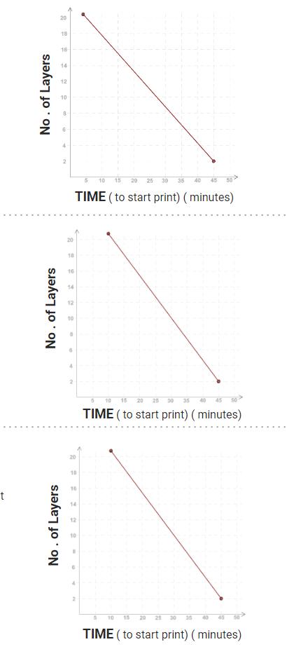
In this research’s initial implementation of additive manufacturing of concrete, dif ferent specimen types were produced. Different testing setups, the influence of concrete age and interval time on the mechanical properties were investigated. Therefore, dif ferent testing series with interval times from 1 to 40 min were conducted. It should be noted that the investigated interval times were set equal to the concrete age after mixing concrete at the beginning of a printing event.
•
•
•
•
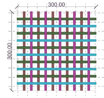
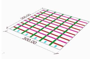
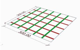
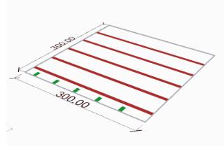
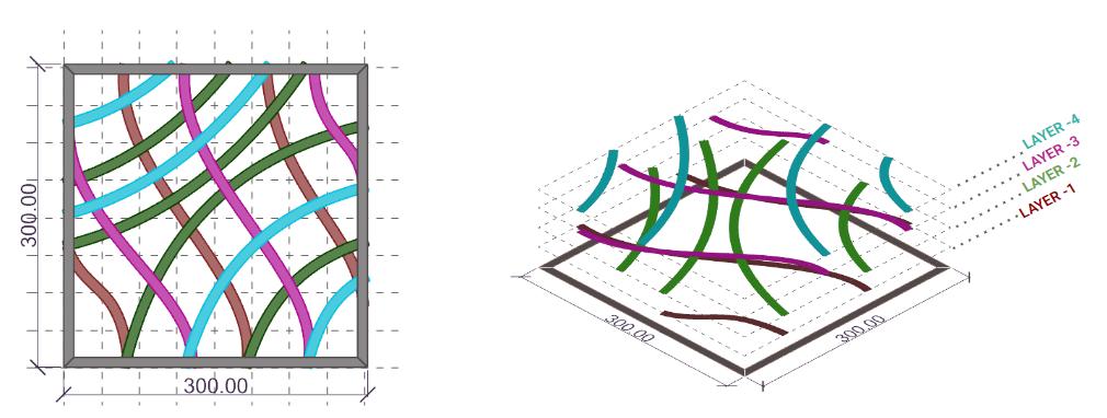
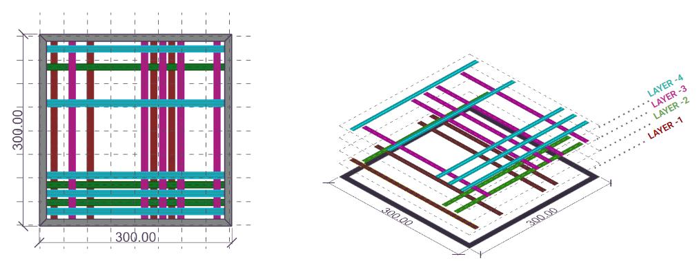
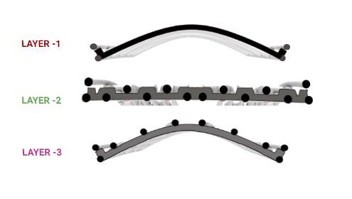
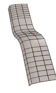
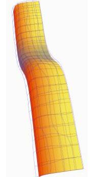
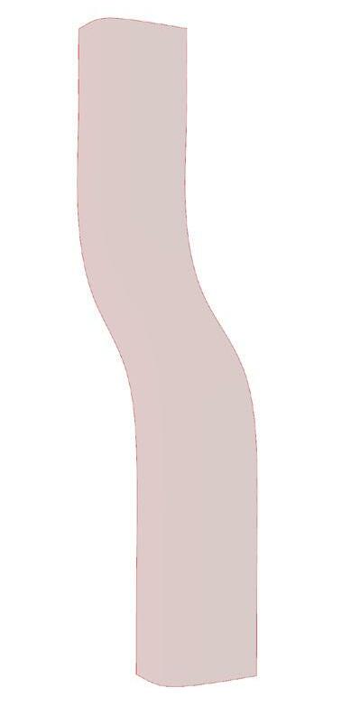
 GEOMETRY LAYERS
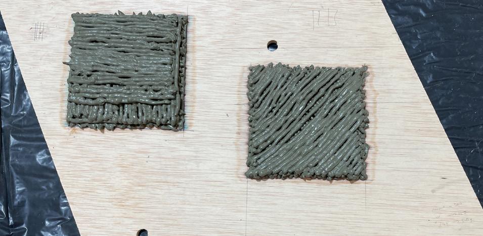
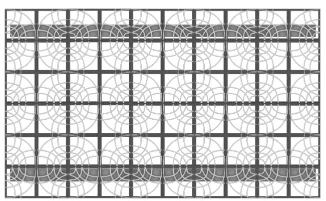
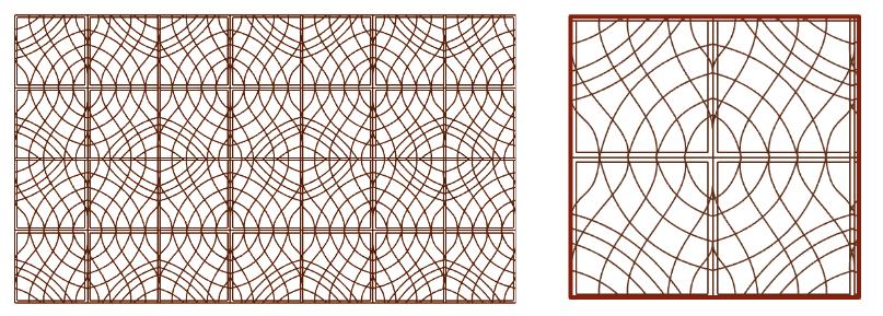
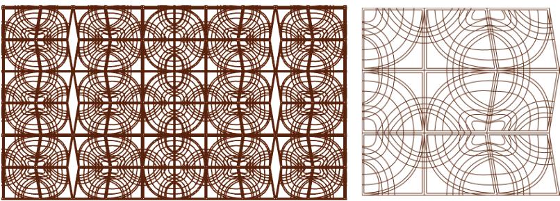
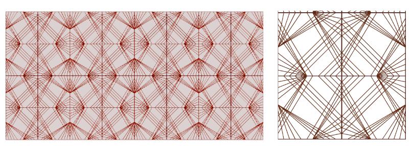
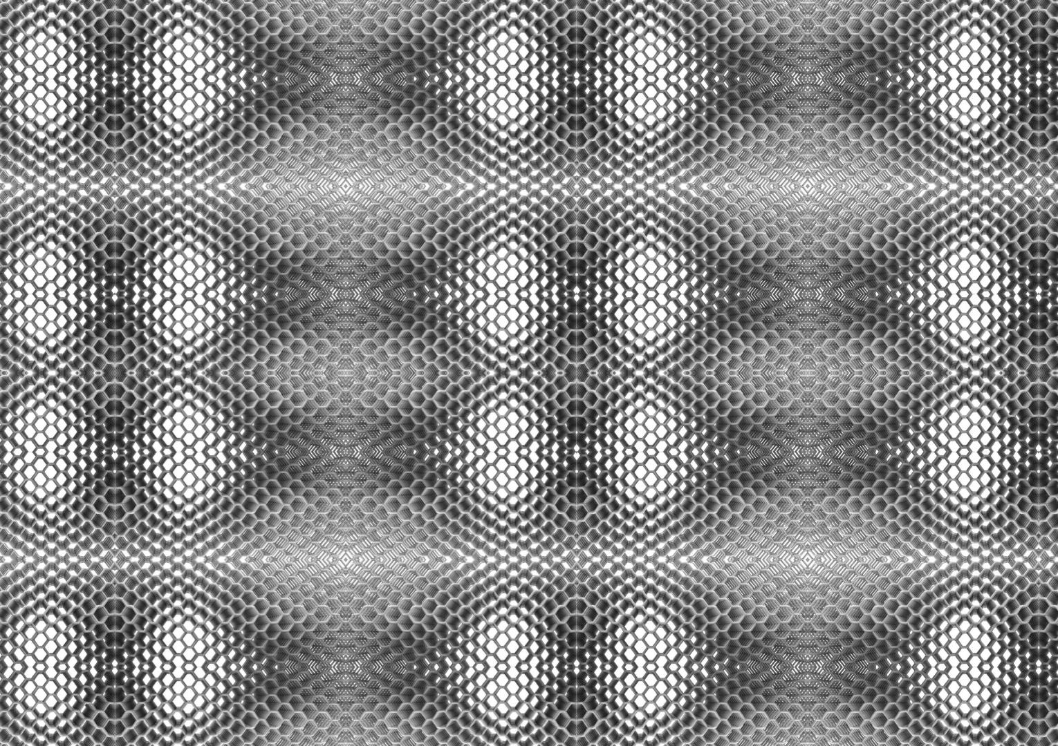
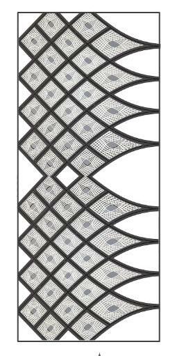
Here are some wall texture design catalogue which are mostly been explored in diagonal and hexagon, which are the most stable geometry with continuous printing concept to develop a texture.
 FACADE OPTION - 1 ( WAVES LINES )
WALL TEXTURE OUTPUT
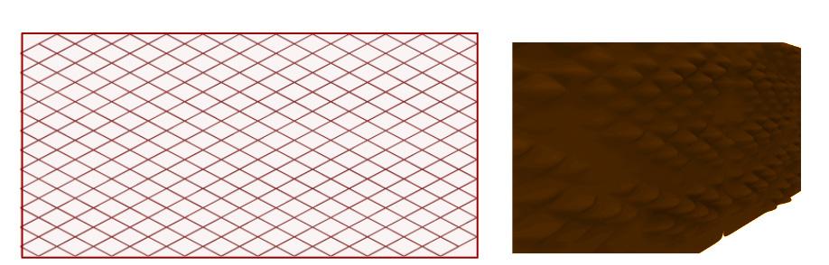
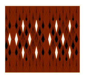
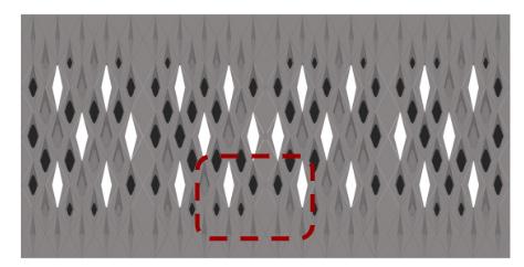
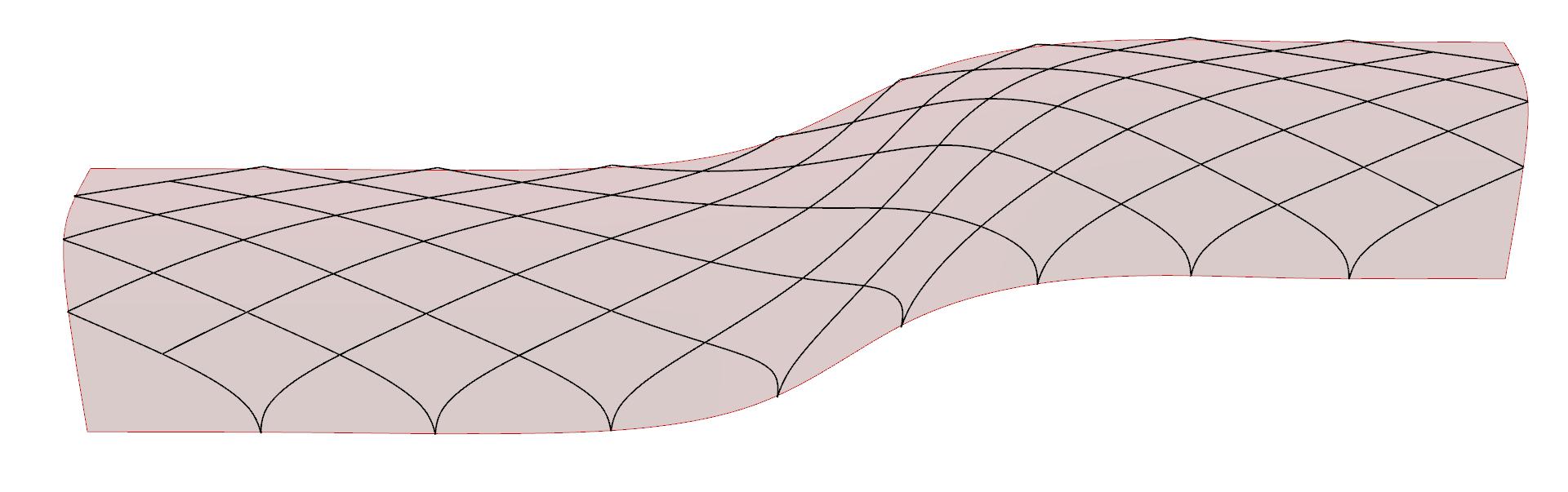
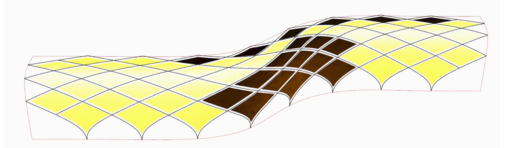
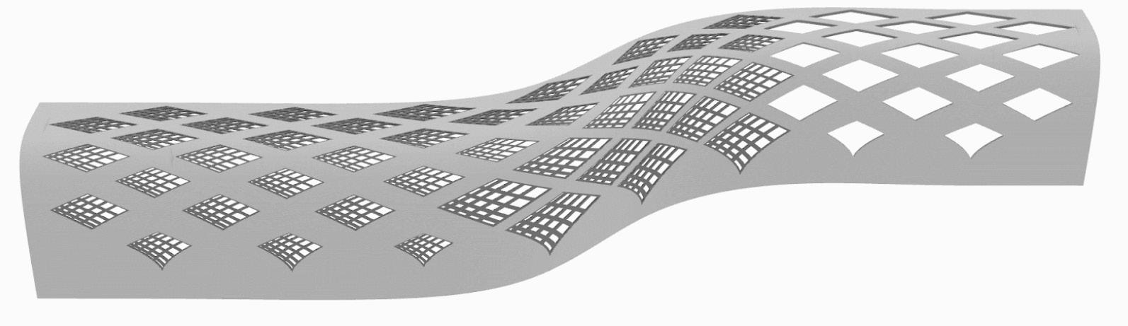
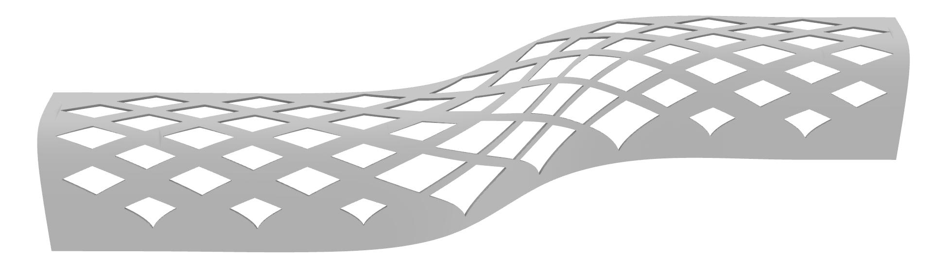
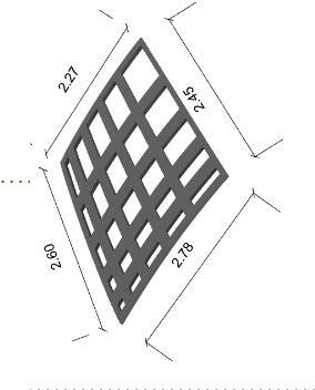
FACADE OPTION - 2 ( DIAMOND GRID)
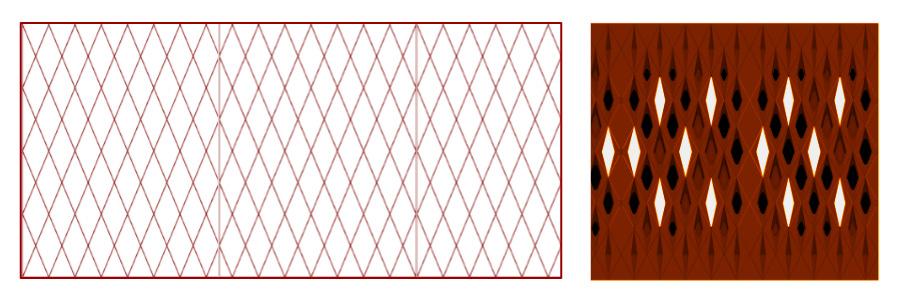
WALL TEXTURE OUTPUT WITH OPENINGS
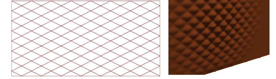
FACADE OPTION - 3 ( DIAMOND GRID ) EQUATION BASE BUMPS
WALL TEXTURE OUTPUT
FACADE OPTION - 4 ( DAIMOND GRID) WALL TEXTURE OUTPUT
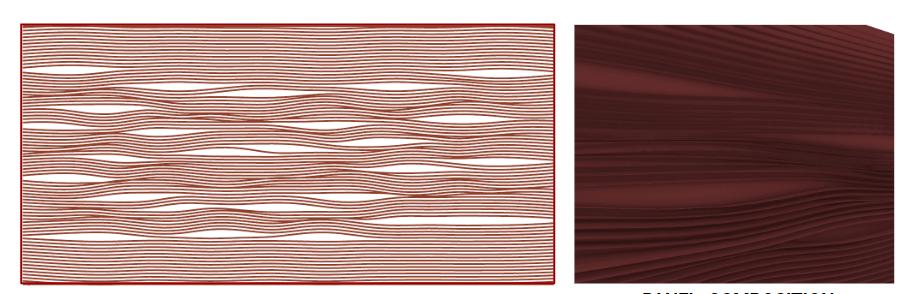
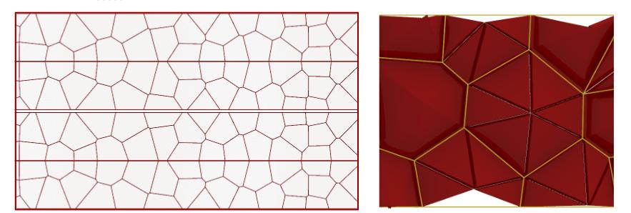
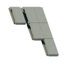
FACADE OPTION - 5 ( VORONOI GRID) PANEL COMPOSITION
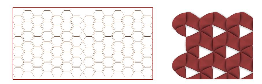
FACADE OPTION - 6 ( HEXAGON GRID) PANEL COMPOSITION
FACADE OPTION - 1 ( WAVES LINES )
WALL TEXTURE OUTPUT
FACADE OPTION - 2 ( DIAMOND GRID)
WALL TEXTURE OUTPUT WITH OPENINGS
FACADE OPTION - 3 ( DIAMOND GRID ) EQUATION BASE BUMPS
WALL TEXTURE OUTPUT
FACADE OPTION - 4 ( DAIMOND GRID) WALL TEXTURE OUTPUT
FACADE OPTION - 5 ( VORONOI GRID) PANEL COMPOSITION
FACADE OPTION - 6 ( HEXAGON GRID) PANEL COMPOSITION
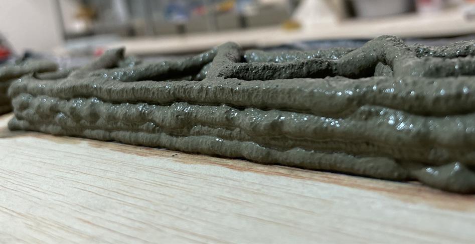
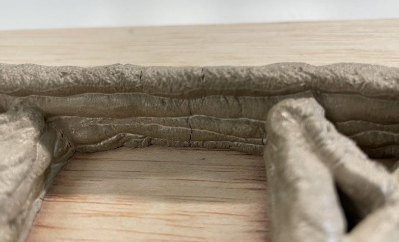
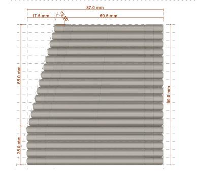
Initially, the continuous prototype got collapsed , because the below layer was not cured enough to withstand against the weight of the above layer. Another reason is due to the segregation of water from the mixtures. As per the material information, in the prior experiment, we see as we go higher in printing and material starts to decrease in the extruder, the pressure for printing also increases. So, due to the pressure base set up, the material mixture inside the cartridge gets into compression which results in the segregation of water before printing itself. So, the next step was to divide the same wall into the part, extrude it and then assemble it. Here, instead of the whole wall, a part of the textured wall was extruded which have bumps in a diagonal grid.
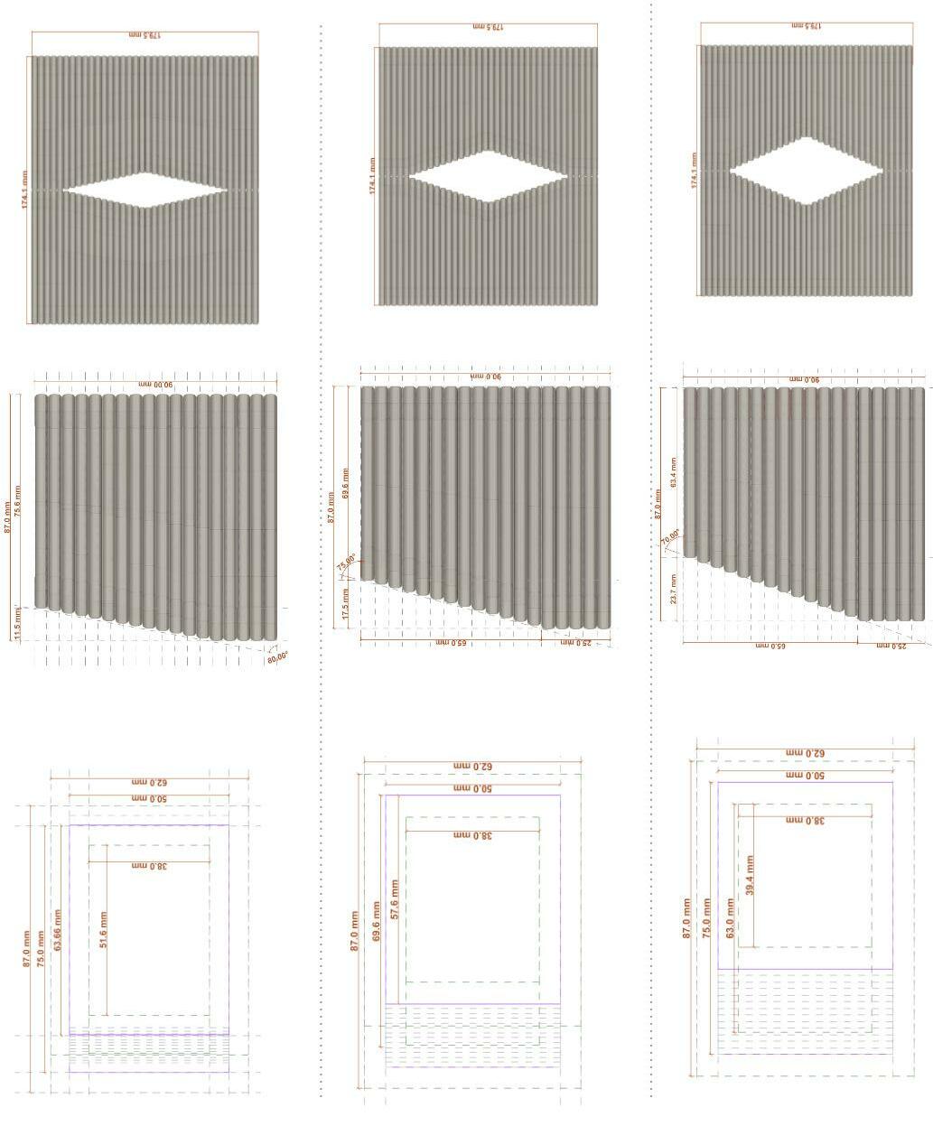
• Layer Height - 5mm
• Layer Thickness - 12mm
• Cantilever - 0 mm
• Rotation ( X axis ) - NO
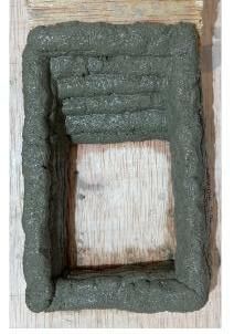
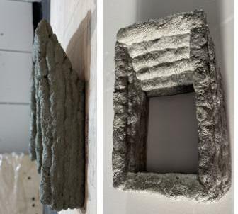
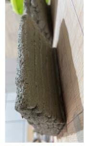
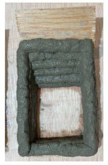
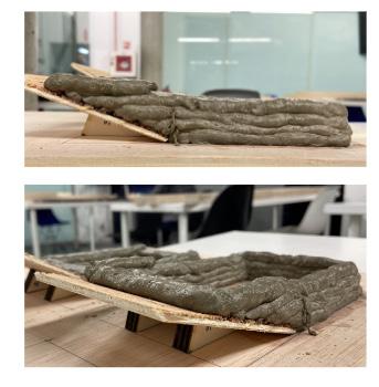
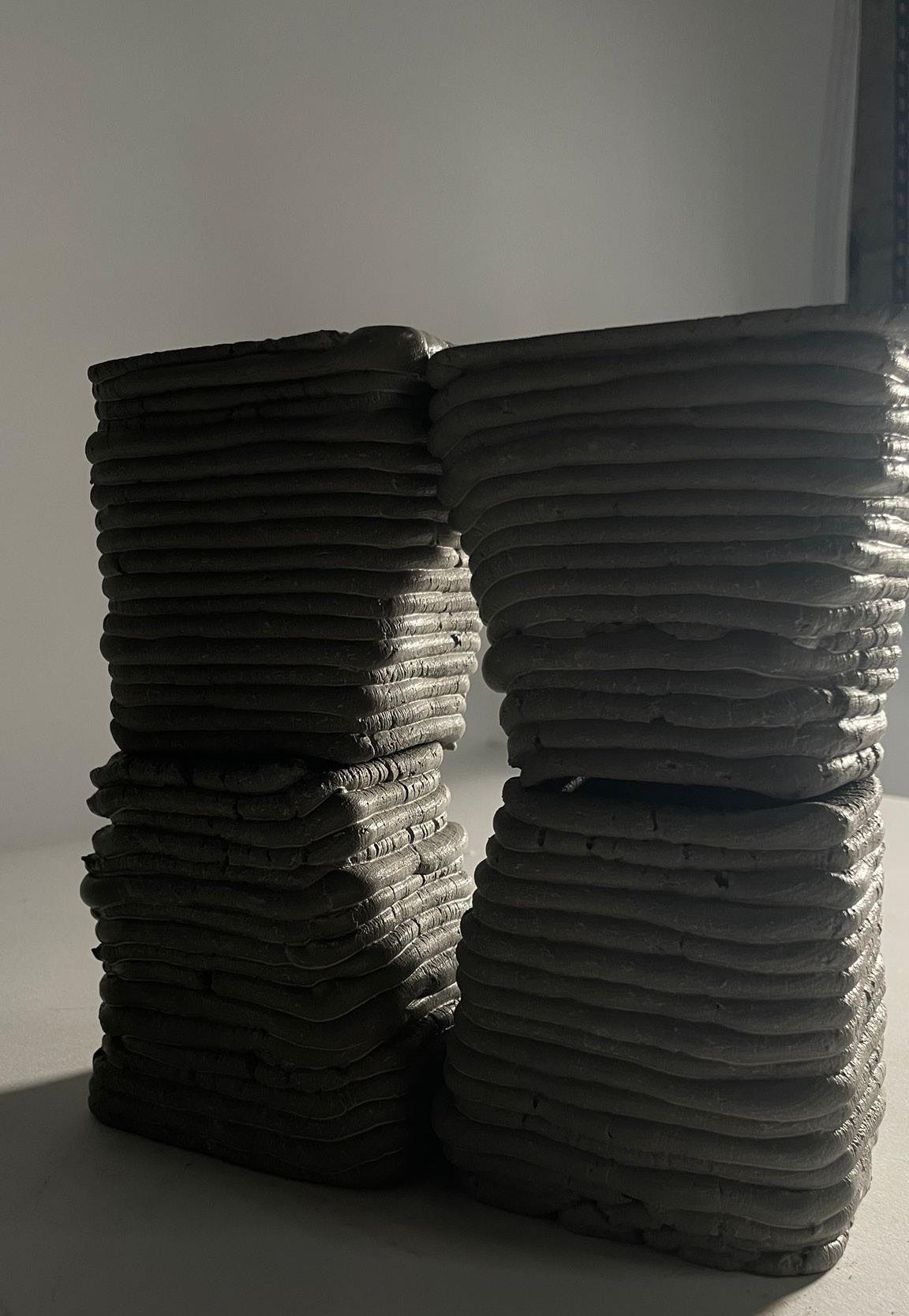
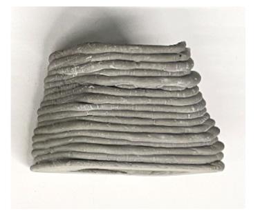
After the brief knowledge of material ratio with robotic printing, the second step is to continuously print a textured wall to understand how much height I can achieve with this robotic setup. The whole process is done with any reinforcement.
• The process was to have continuous printing but was a failed attempt because the below layer was not cured enough to carry the load of the new layer.
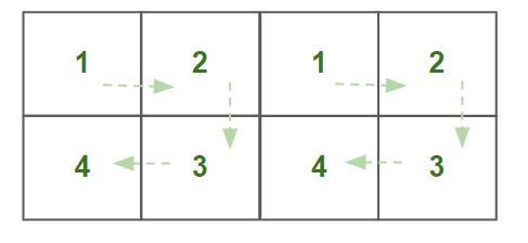
• So the second attempt was to print a part of the textured wall with a block concept. Where I divide the wall into 3 blocks and print the block separately and then assemble it.
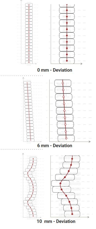
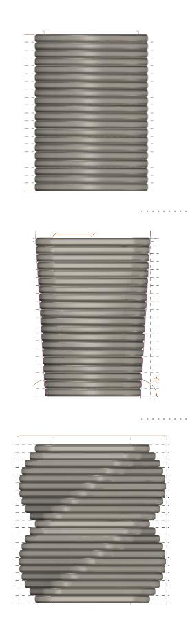
• In conclusion with the second attempt, the concept of block printing was a bit successful as there was no collapse of the wall, but the layers were uneven. Because of the uneven layer, the block output was uneven. There was a slight difference between digital and physical output.
•
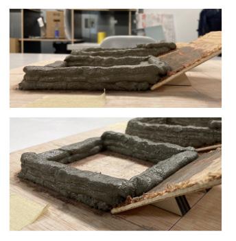
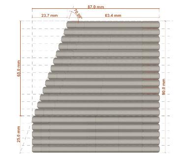
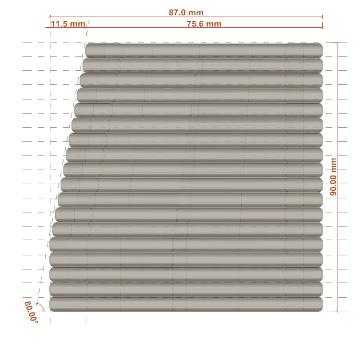
As continuous wall printing was a failed experiment, the third stage was to develop the wall with the block system technique. Here, the whole wall will be divided into a grid system and each module will be printed separately then after 50% cured they will be assembled together to form a wall system. Also, in this experiment, an exploration of the cantilever is performed. After analysing the wall we calculated the average angles to perform the test and those angles were between 80 to 65 degrees of which change on the basis of an equation.
• So after these experiments if found out that printing higher is a challenge as I am not using any accelerant in the mix, which helps to cure the below layer.
• The system which I was using which is a pressure based extruding is not good for printing vertical as the below layer collapse while printing above, so here I took a major turn of changing the strategy by printing horizontal and wider and creating a panelling system.
GEOMETRY - 1 Results
- No crack formation
- 10% form deformation
- No accelerant
- Uneven Layers - 5 minutes between mixing and printing
GEOMETRY - 2 Results
- No crack formation - 10% form deformation
- No accelerant
- Uneven Layers - 12 minutes between mixing and printing
GEOMETRY - 3 Results
- No crack formation
- 25% form deformation
- No accelerant
- Uneven Layers - 20 minutes between mixing and printing
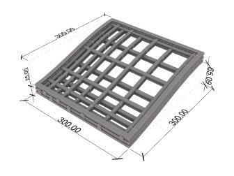
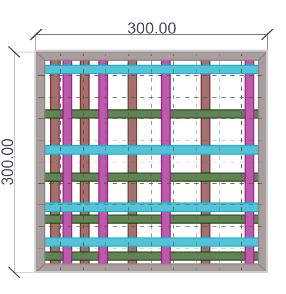
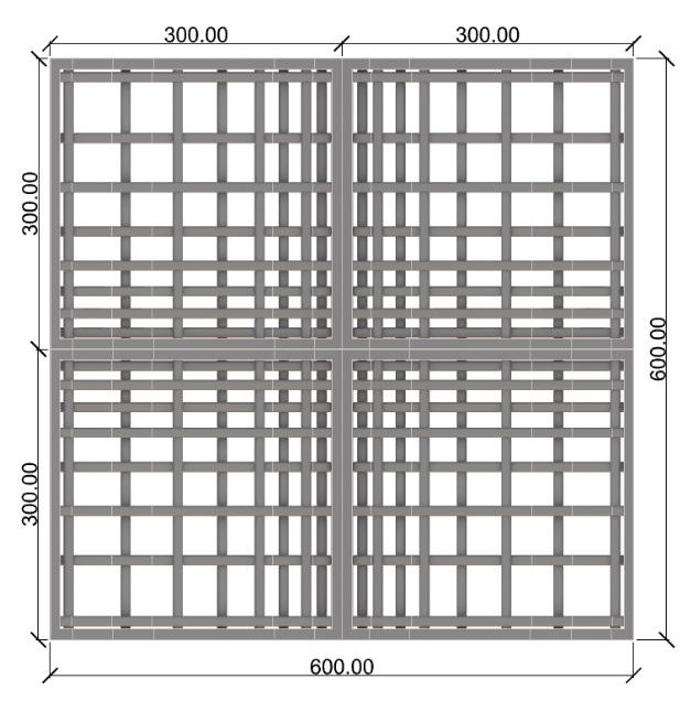
As continuous In this stage of exploration, the concept of creating an opening and pattern on the wall is the same, the only thing that changed is the design strategies. So taking further with the concept of block printing I will design a panel system with the concept of Jali perforations.
Before going into fabrication, first understand the concept of panel wall and their geometric aggregation, which result in a performative facade wall.
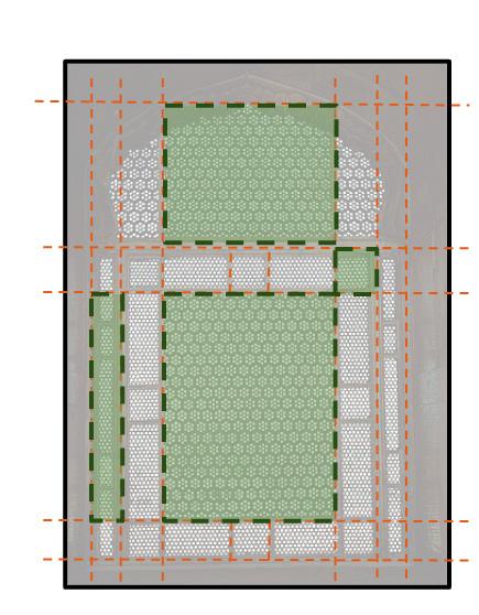
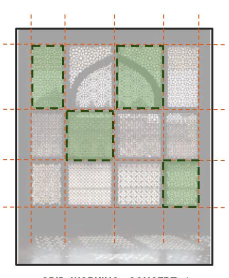
Ornamental & performance-based screens have been a significant architectural feature for many decades in Islamic Architecture. The wall not only plays an aesthetic role but also played a major role in tackling natural conditions such as passive cooling and lighting screens in structures.
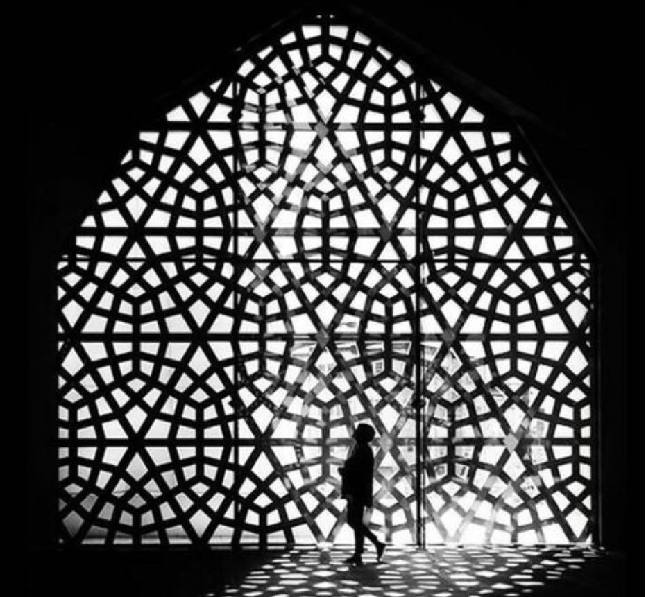
Benefits of Jali Wall :-
• Curtailment of heat in both hot-humid & hot-dry climate regions.
• Orchestration of Light.
• The mechanical version of an air-conditioning compressor
• Concealment of Space
Aggregation is not a new concept for the construction industry. Instead of randomly aggregating the geometry, there was an equation for a strong and stable output.
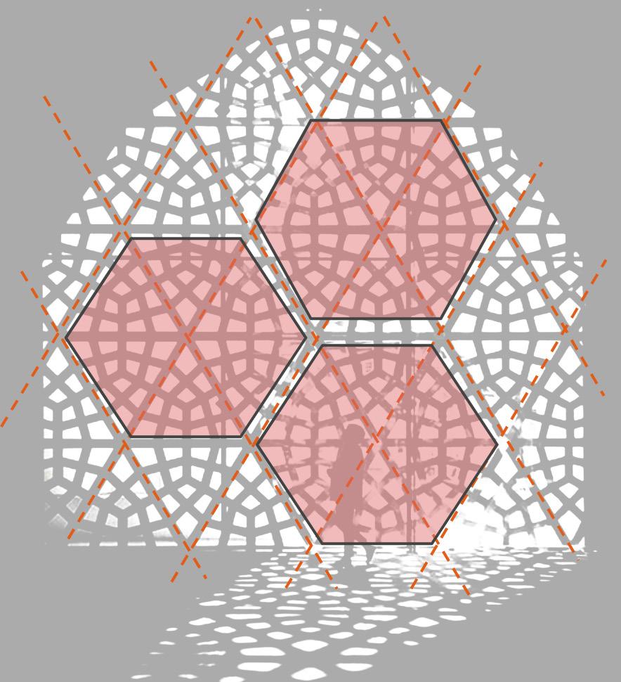
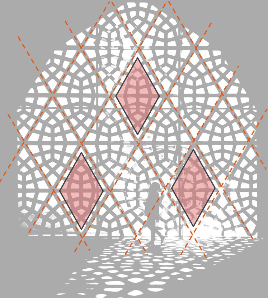
Jalis or screens have been a significant architectural feature for many decades. In earlier times Jali’s not only played an aesthetic role in building design but also played a major role in tackling the natural conditions in building’s ventilation and lighting. The patterns are constantly repeating themselves by creating the illusion of continuity beyond the frame’s physical boundary, thus making it challenging to identify the overall patterns starting and ending points.
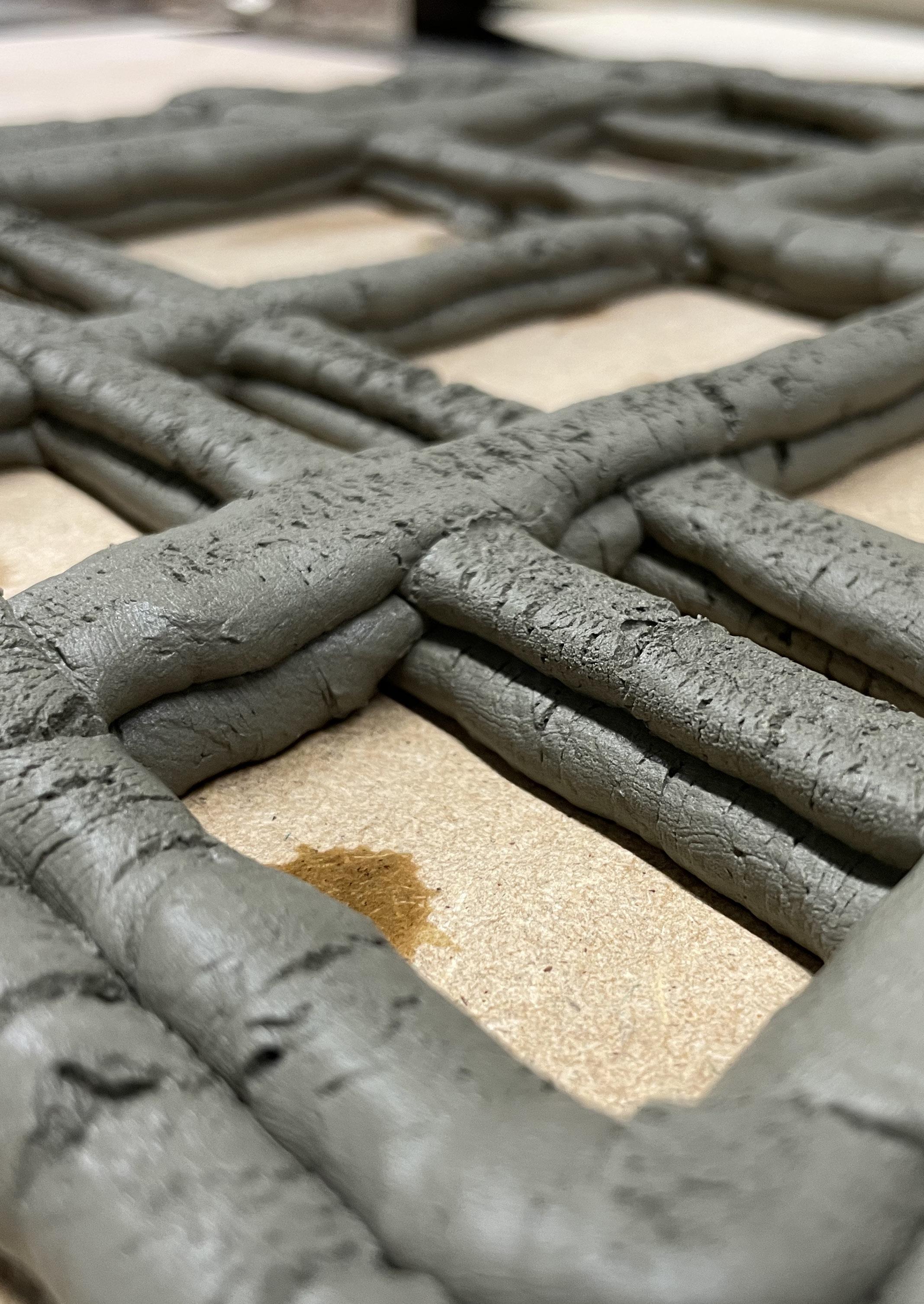
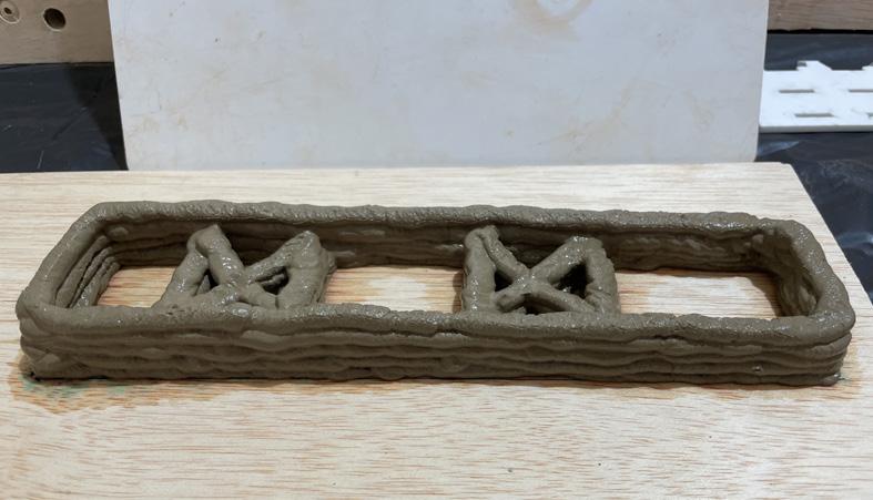
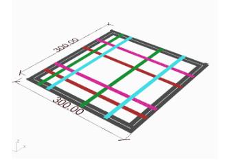
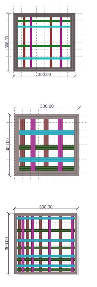
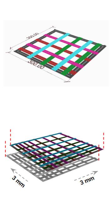
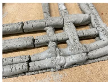
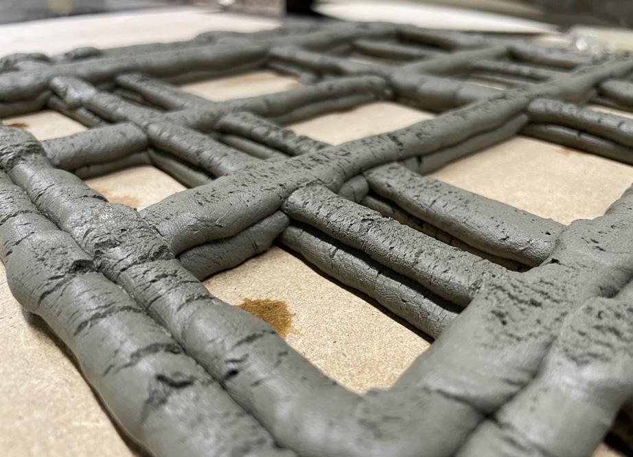
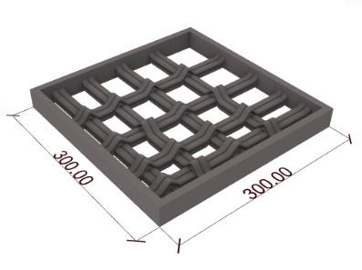
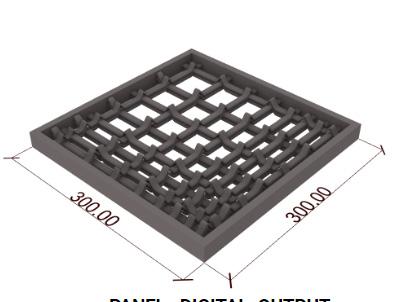
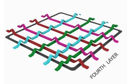
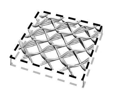
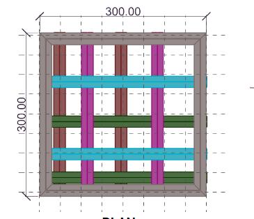
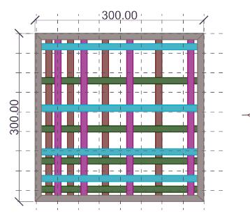
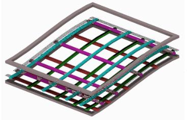
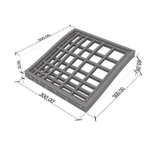
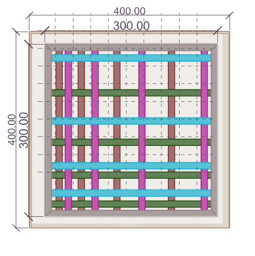
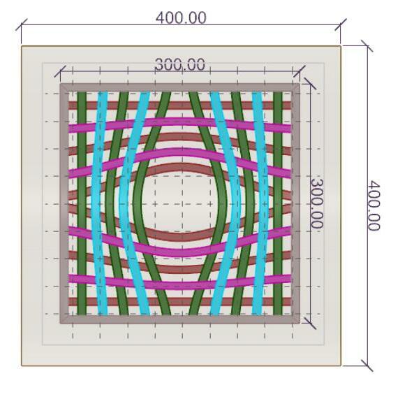
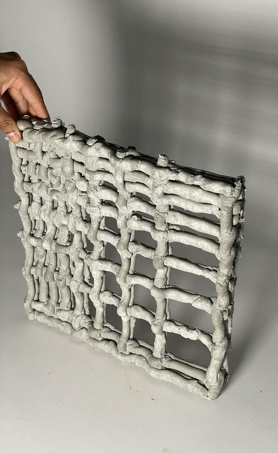
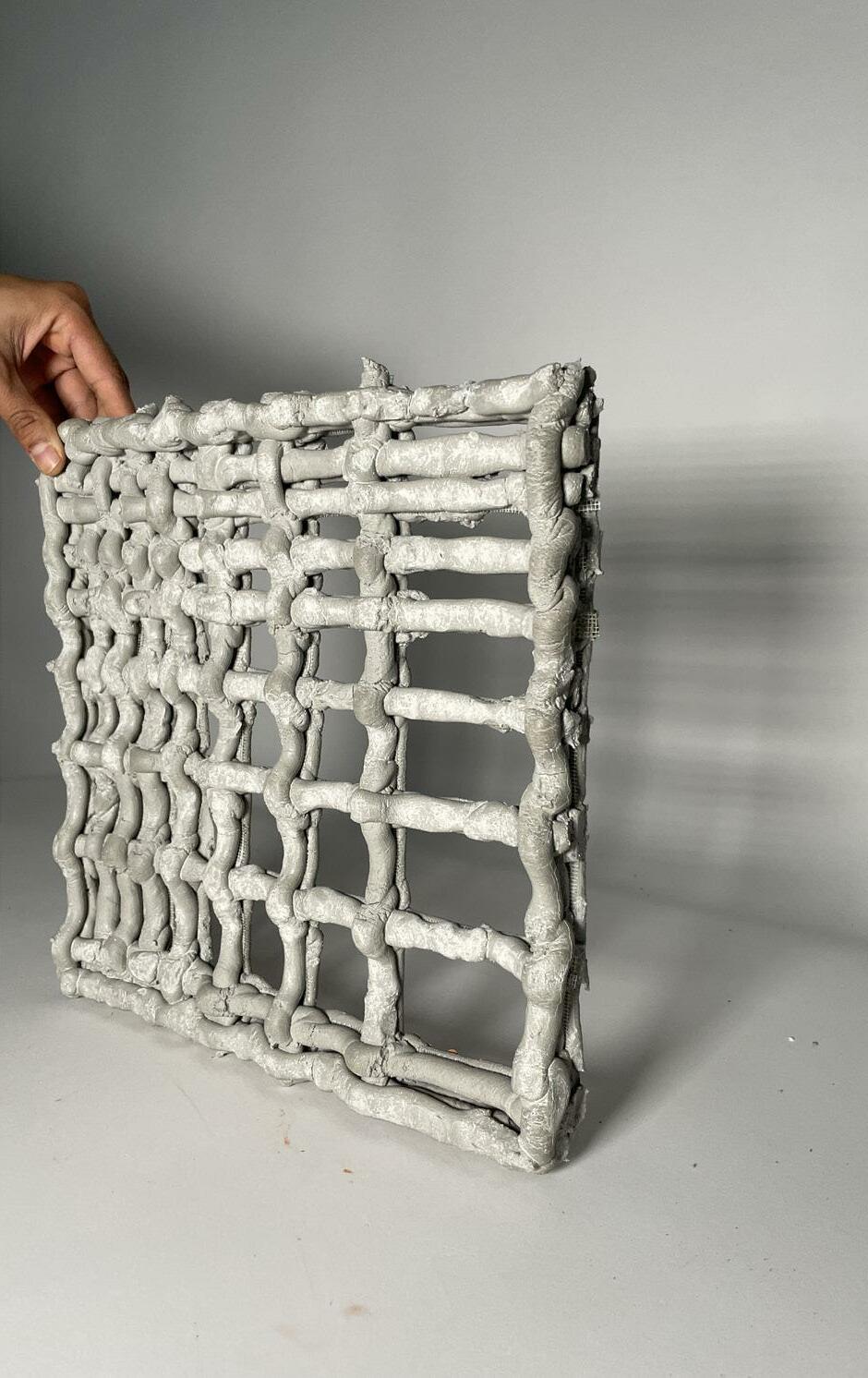
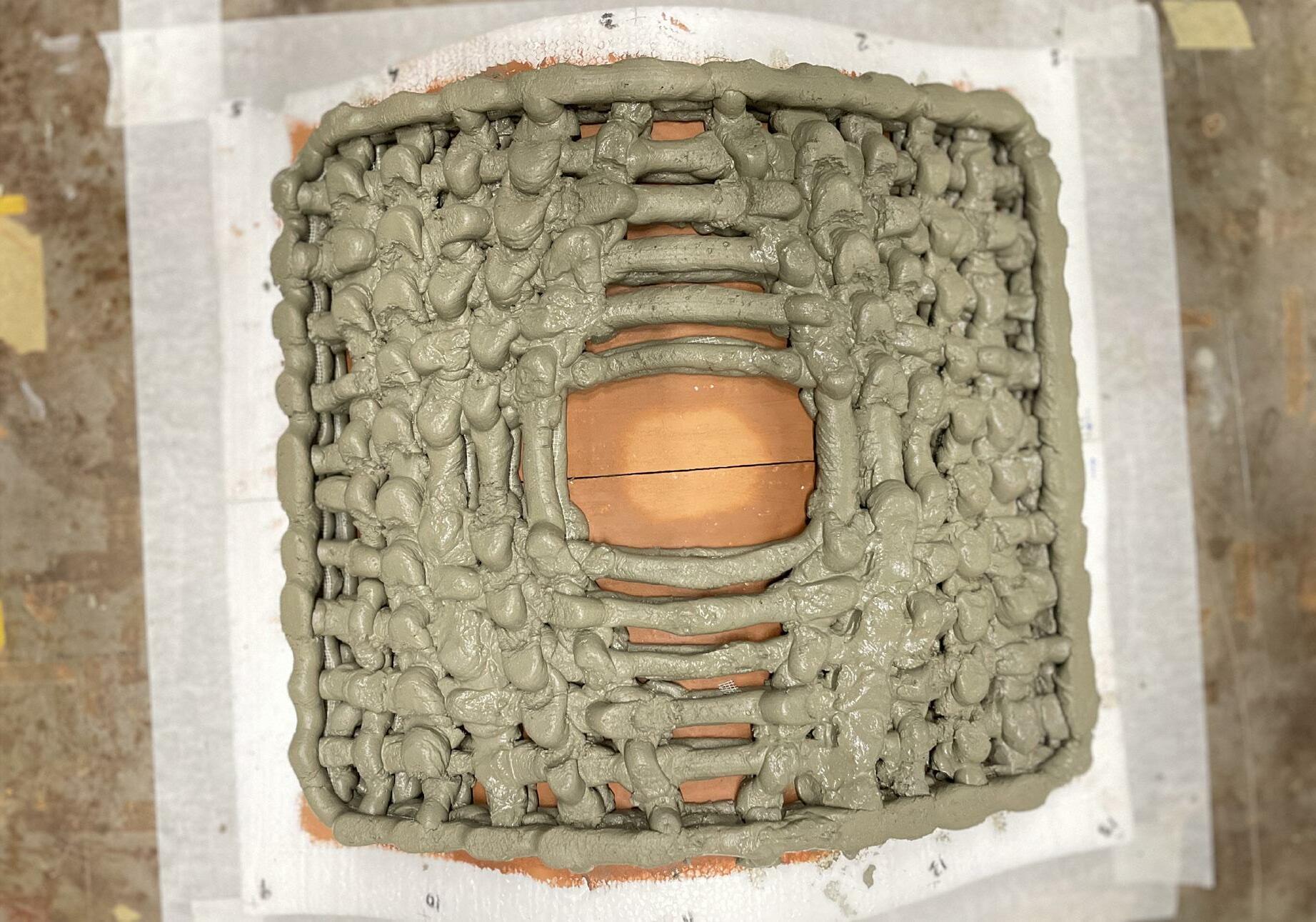
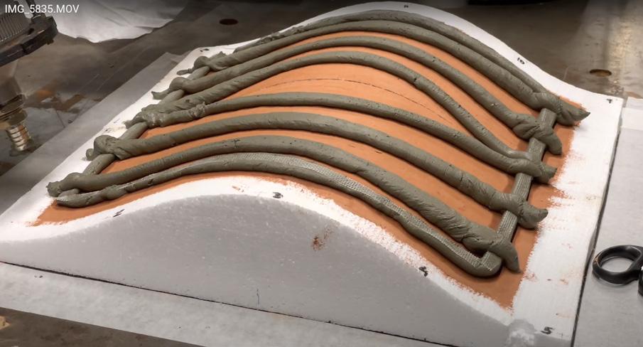
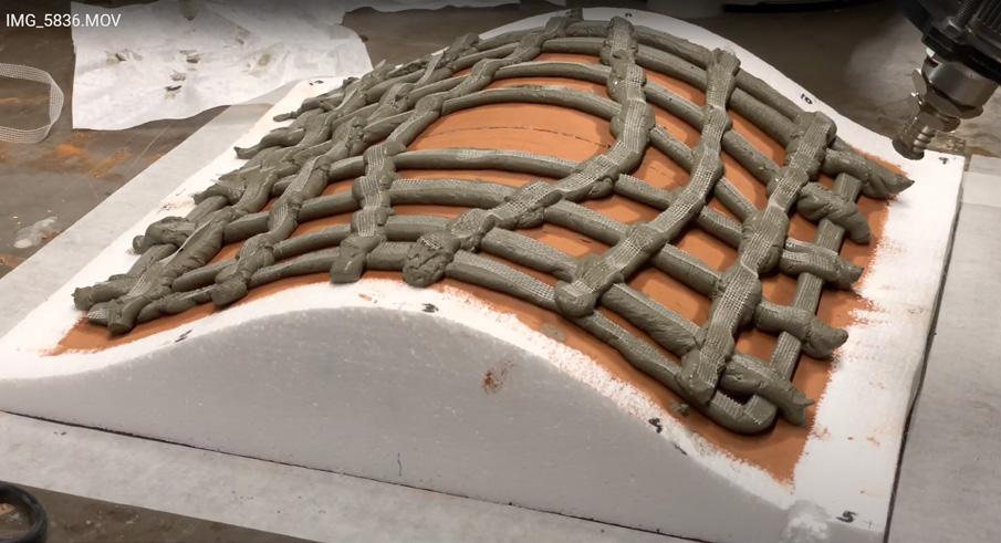
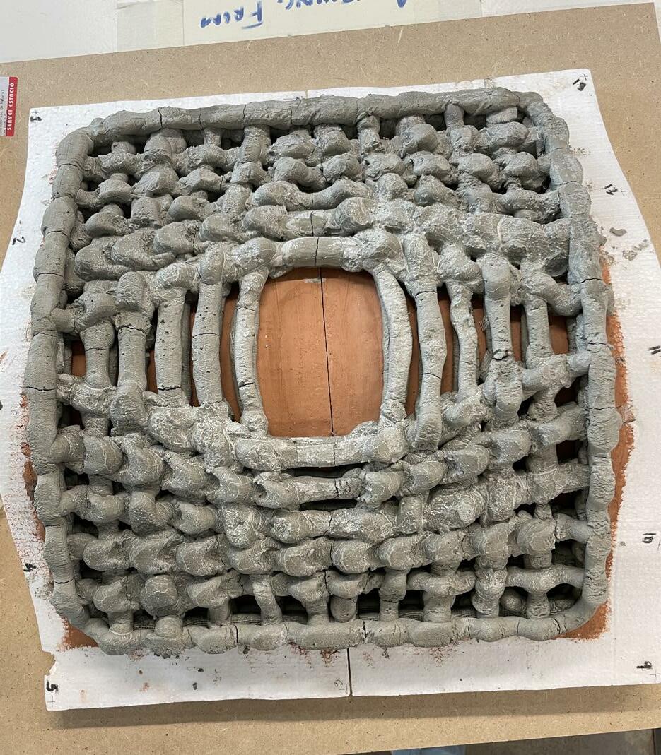
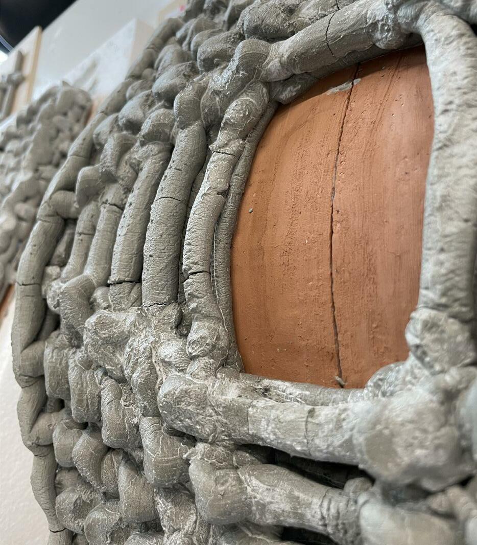
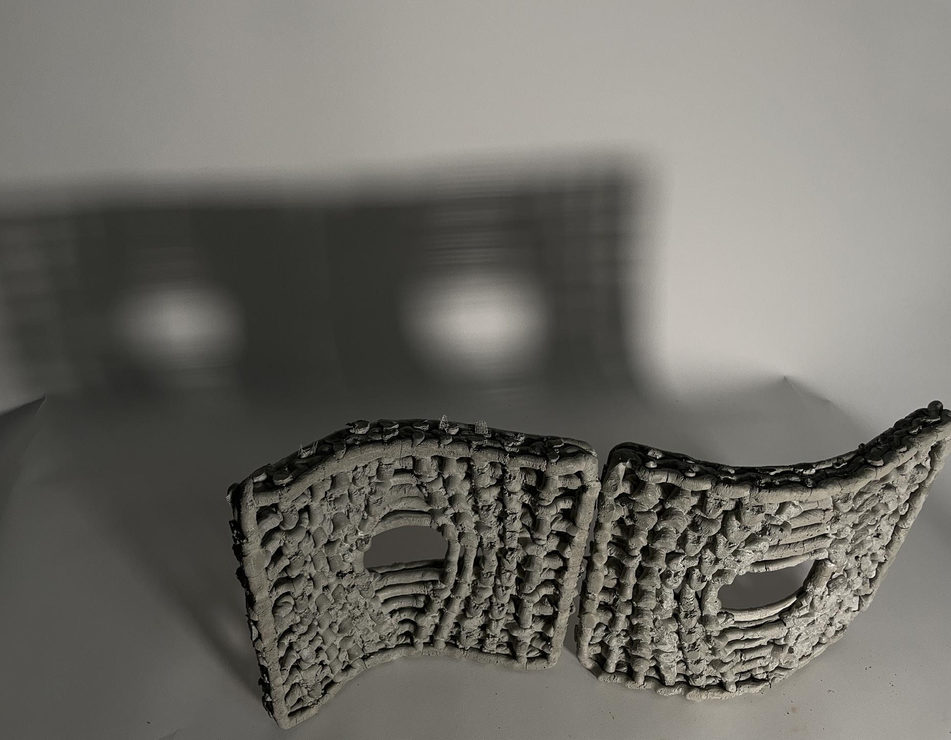
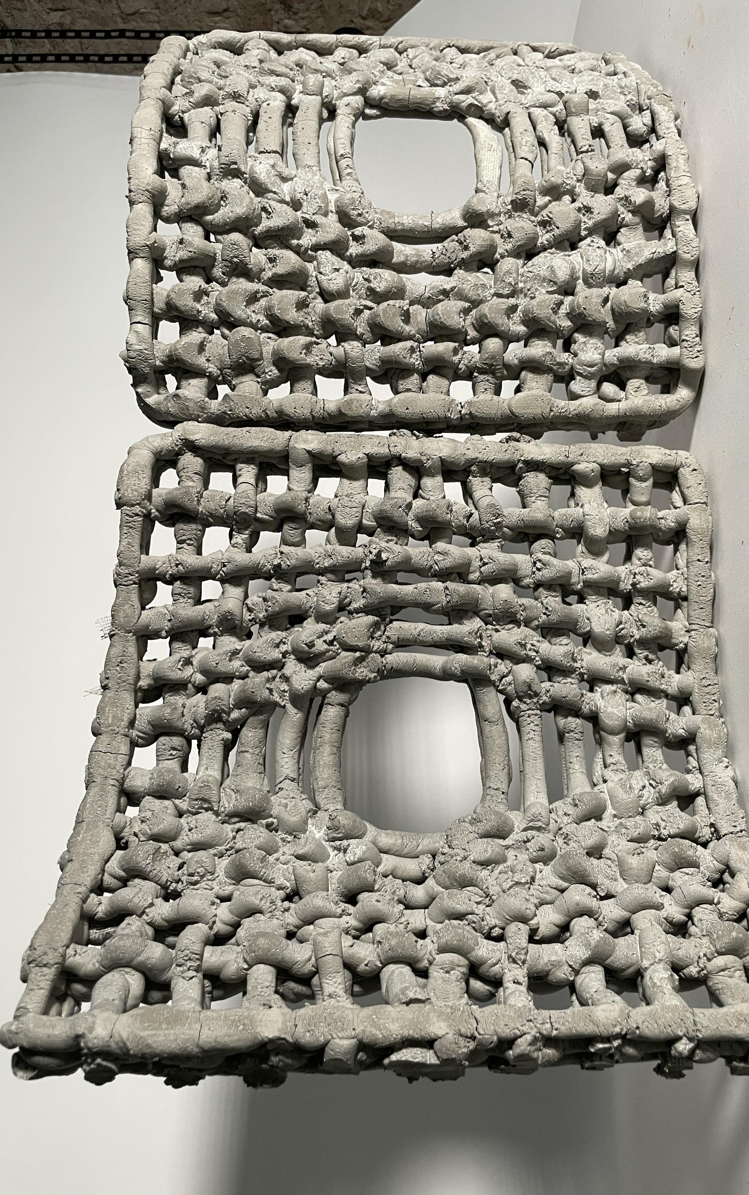
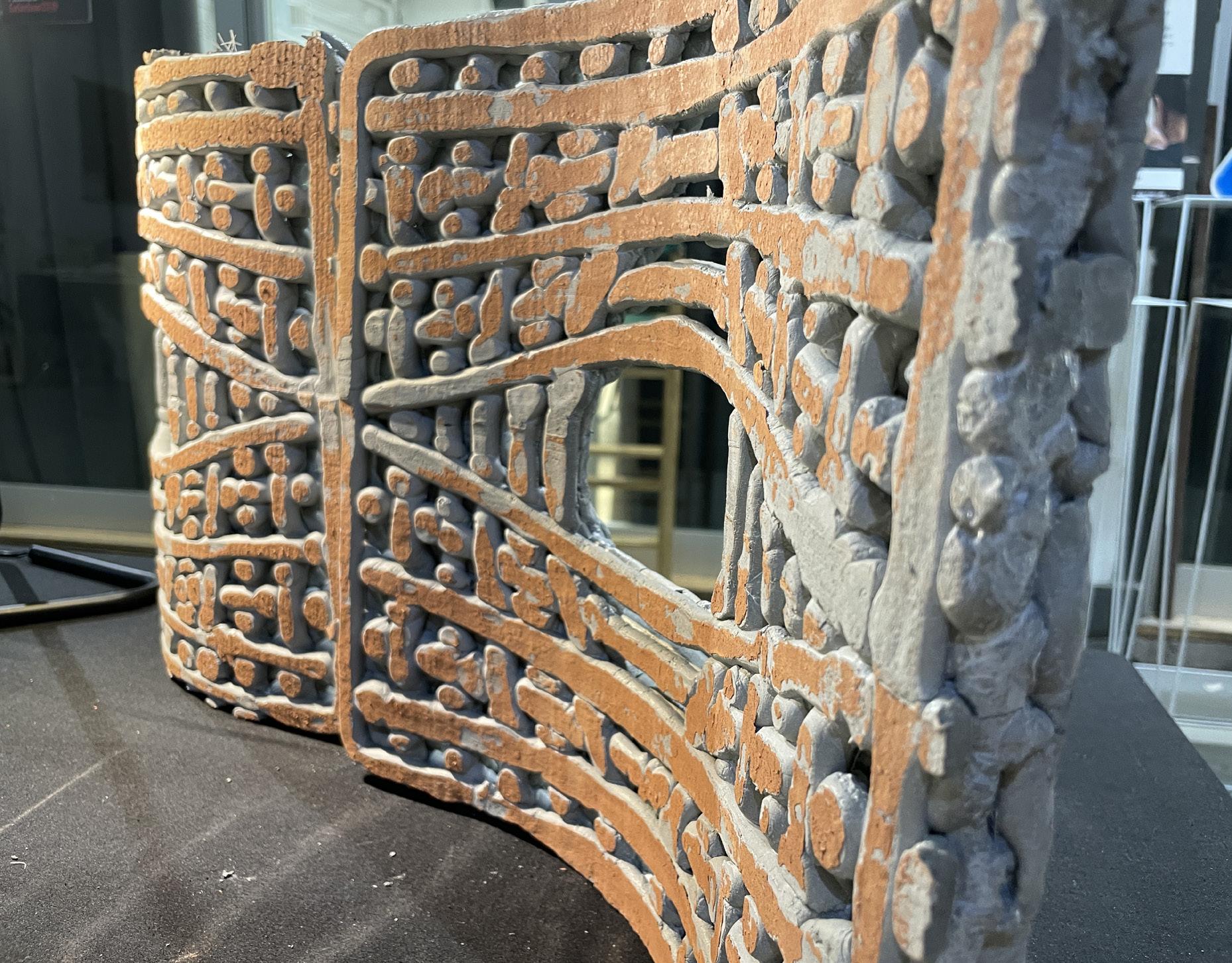
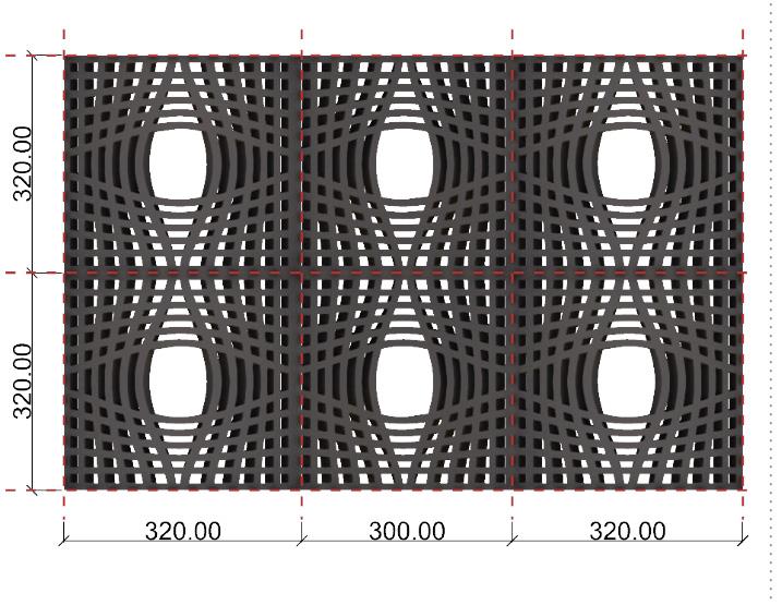
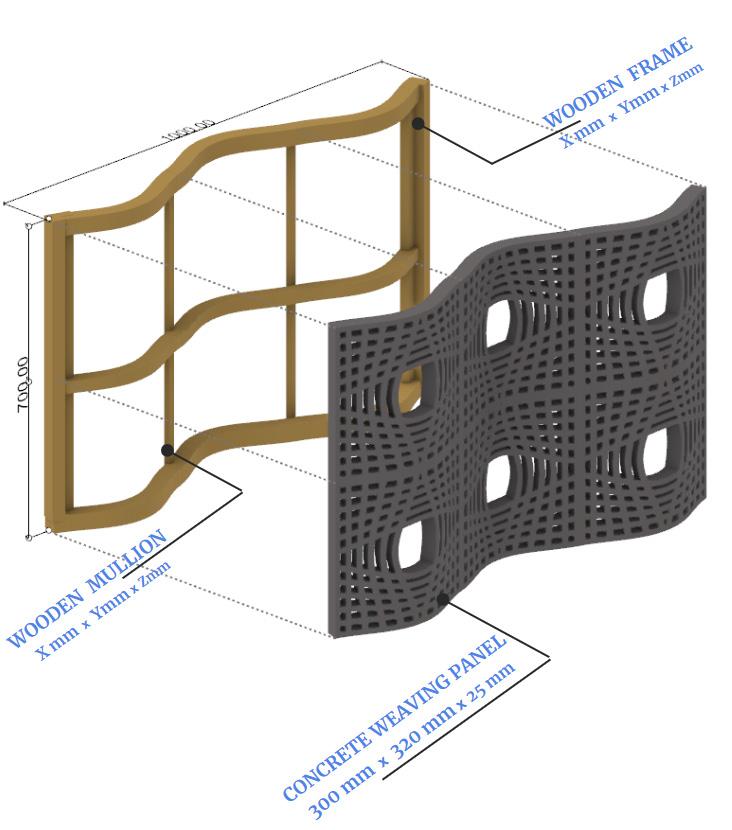
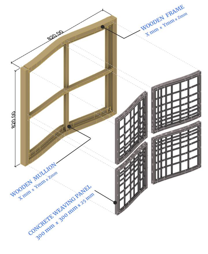
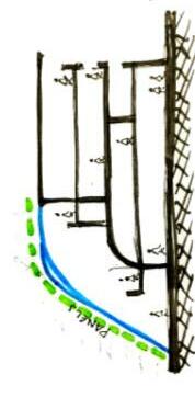
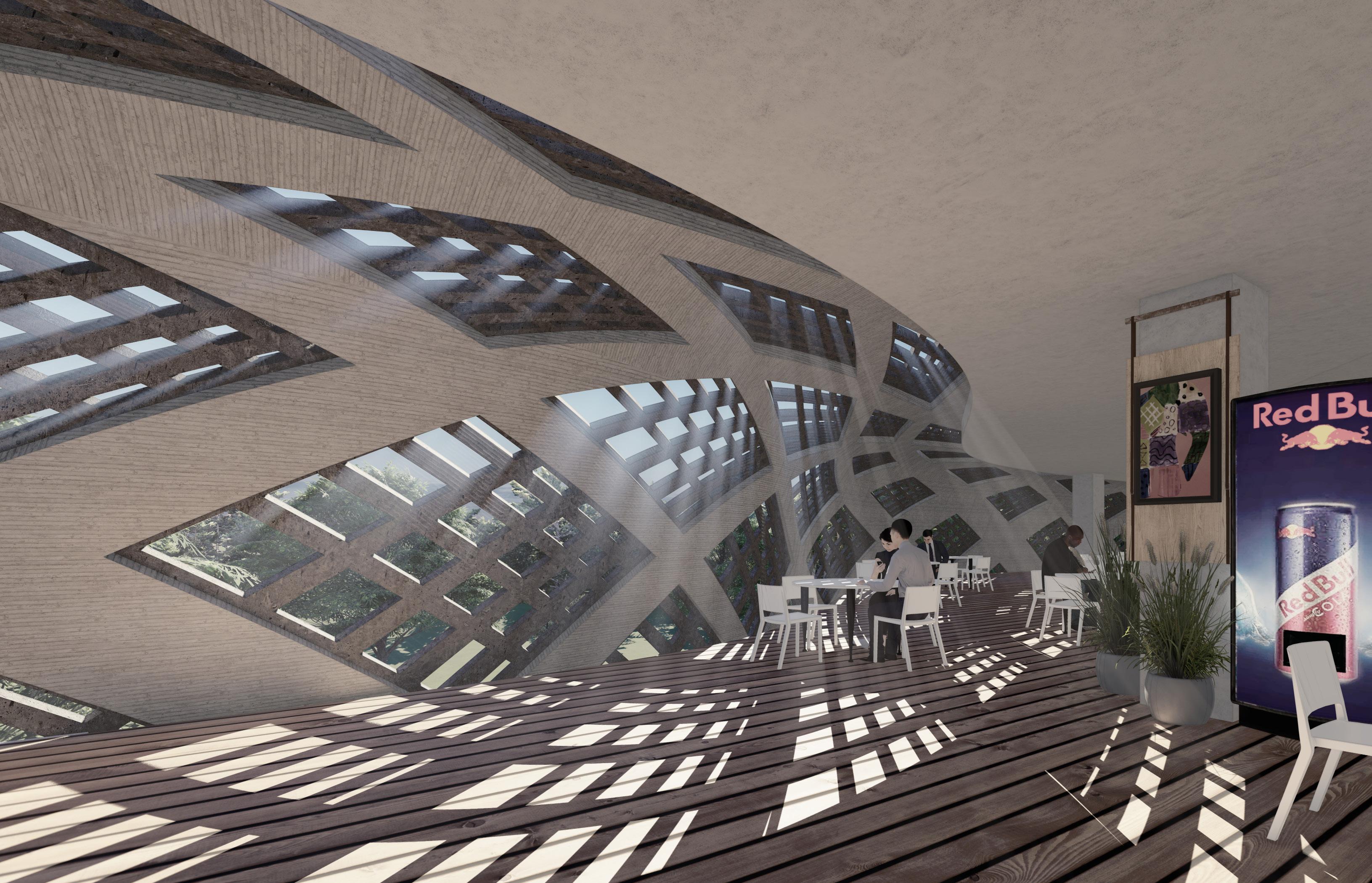
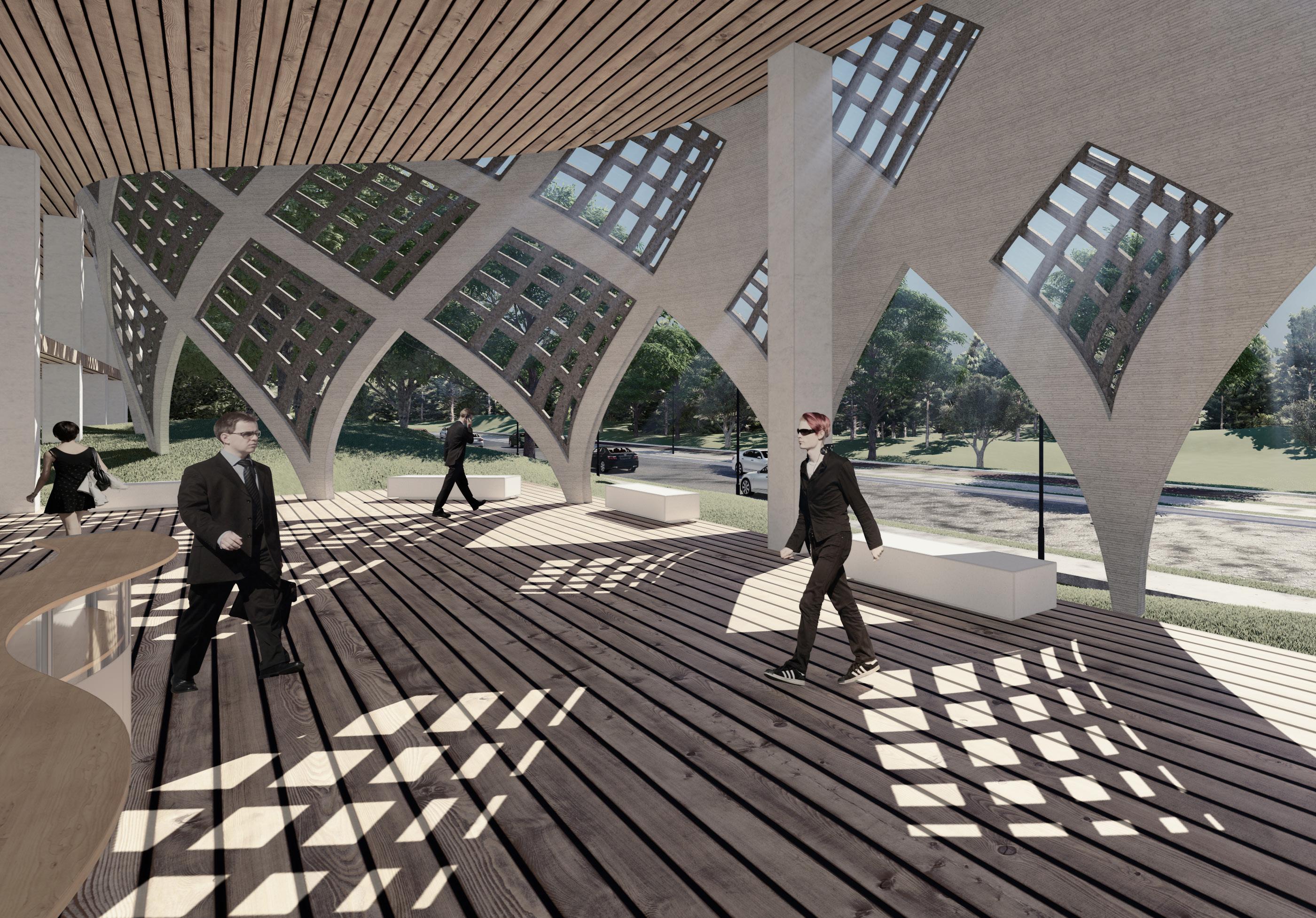
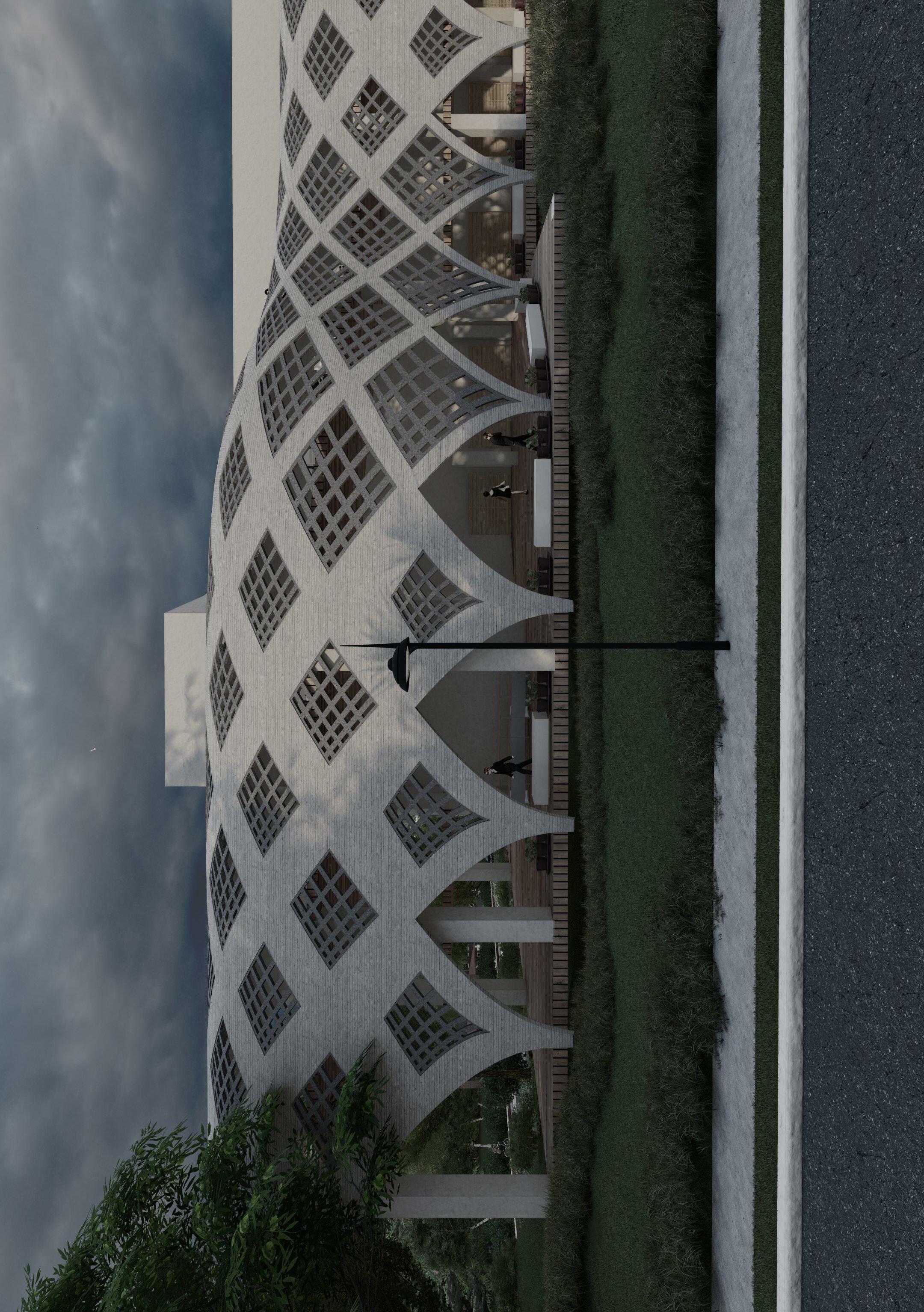
According to the previous set of experiments, I came to the conclusion that printing the whole block with a pressure-based extruder is not a viable technique to go forward with the exploration. As a result, I change the strategy to print vertical and wider and develop a panel system which will be based on radiation analysis. In this process, I com bine 2 techniques which are. i) printing with the concept of weaving and ii) combining those modules in such a way that when finished it looks like a one peice facade skin. Each panel will be extruded separately with respect to their base support and then the panels will be aggregated in such a manner that when assembled will look like one com plete facade.

-
 WEAVING TECHNIQUE
MODULE CONCEPT OF PANELS
WEAVING TECHNIQUE
MODULE CONCEPT OF PANELS
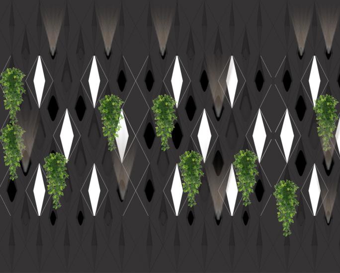
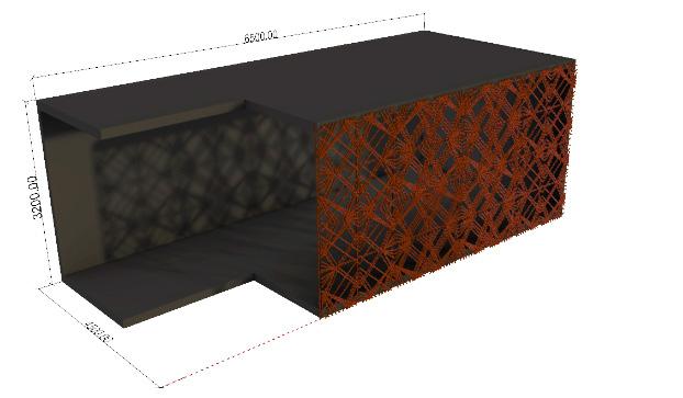
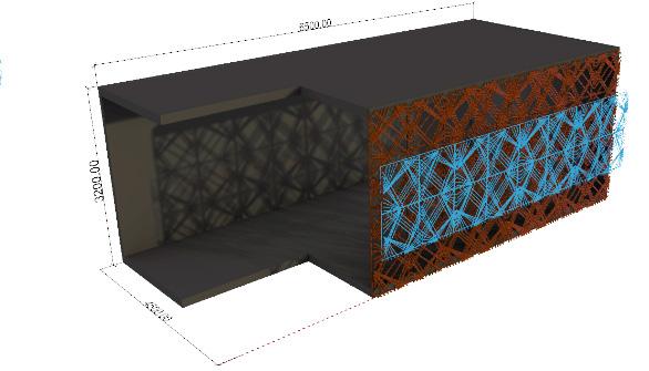
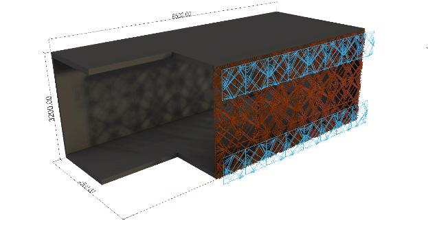
As the panel is designed on the basis of radi ation and sunlight analysis the implementation of panel on the facade surface is based on the required inner space. If the inner space is a pri vate space there will be a double panel system with 30% porosity, if the space is semi-private there will be a double panel at the slab and floor position and at the last part, if the space is enclosed but need a feeling of an open seat ing area, a single panel will be implemented with 50-60% porosity for the light to enter the required space.
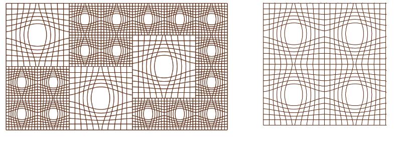
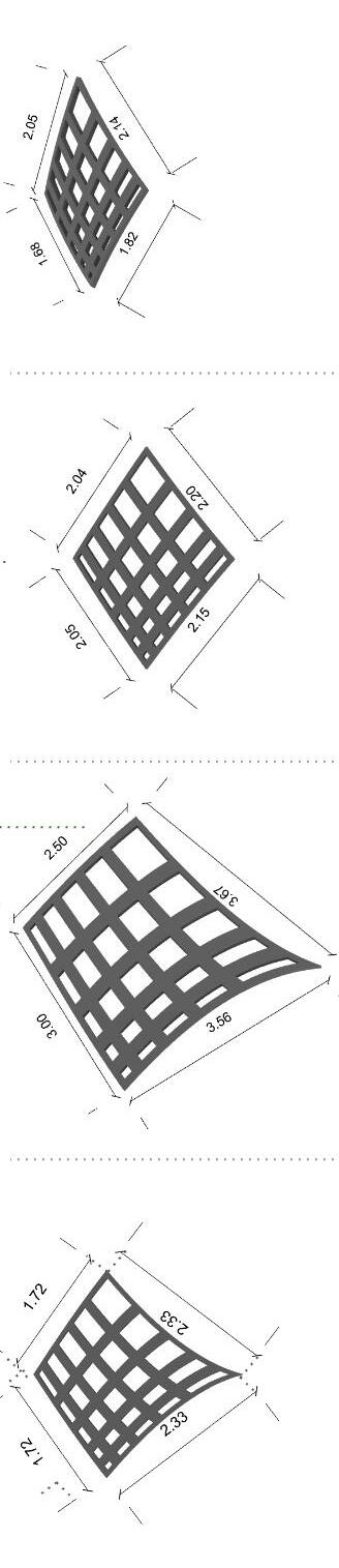
Here is some panel design catalogue which are mostly been explored in quadrilateral and hexagon, which are the most stable geometry when aggregated without any negative space.
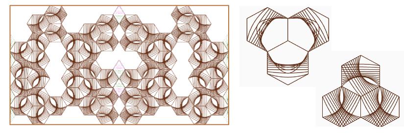

 FACADE PANELS - Option 1 PANEL COMPOSITION
FACADE PANELS - Option 2 PANEL COMPOSITION
FACADE PANELS - Option 3 PANEL COMPOSITION
FACADE PANELS - Option 4
PANEL COMPOSITION
FACADE PANELS - Option 5 PANEL COMPOSITION
FACADE PANELS - Option 6 PANEL COMPOSITION
FACADE PANELS - Option 1 PANEL COMPOSITION
FACADE PANELS - Option 2 PANEL COMPOSITION
FACADE PANELS - Option 3 PANEL COMPOSITION
FACADE PANELS - Option 4
PANEL COMPOSITION
FACADE PANELS - Option 5 PANEL COMPOSITION
FACADE PANELS - Option 6 PANEL COMPOSITION
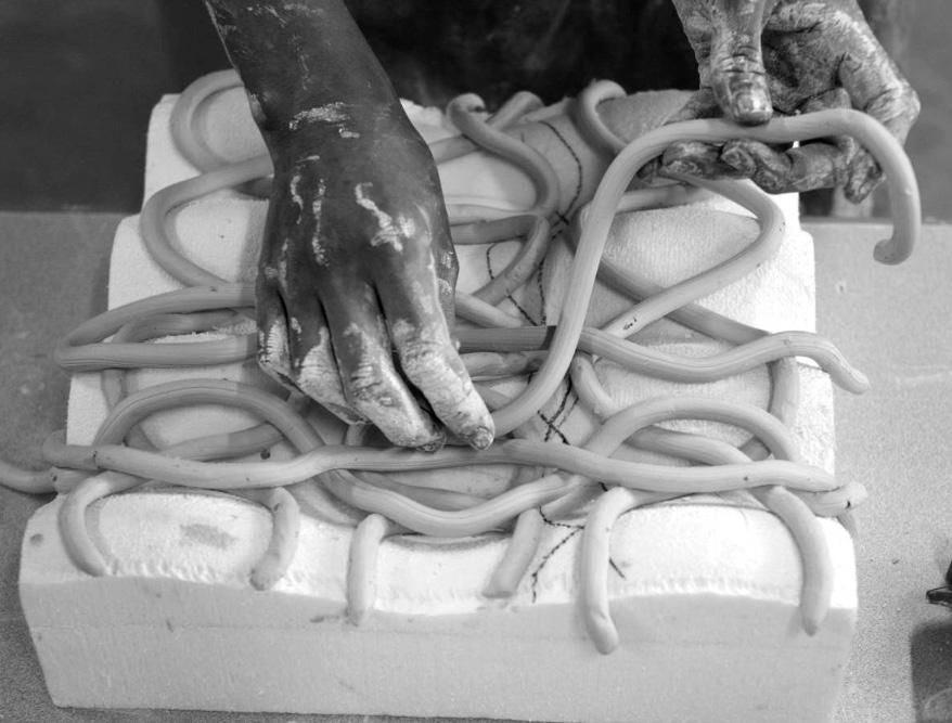
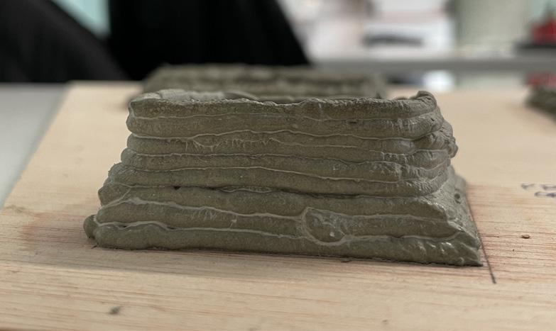
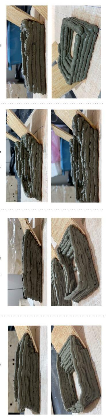
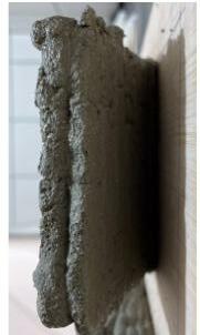
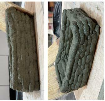
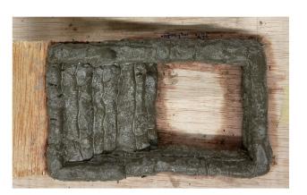
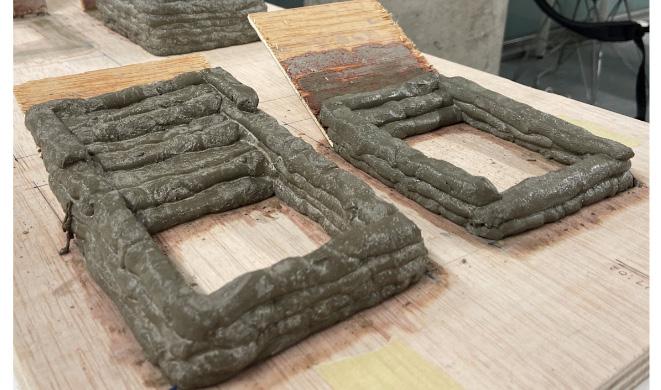
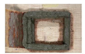
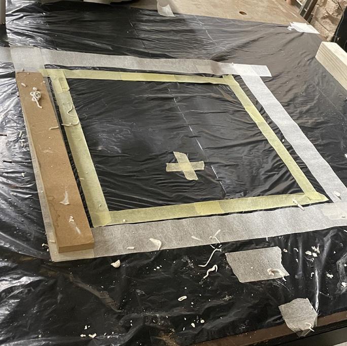
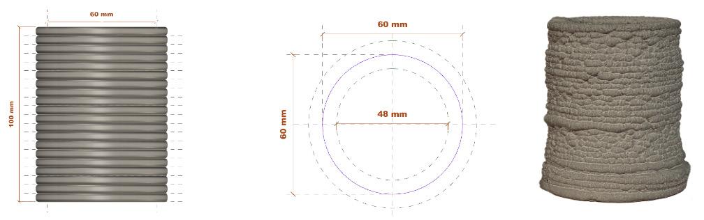
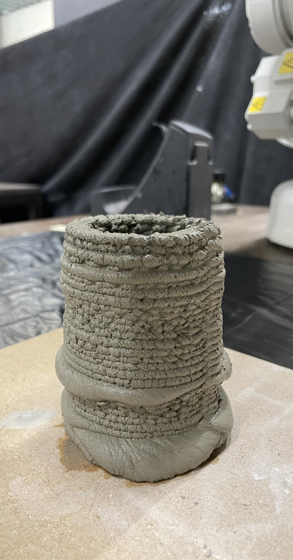
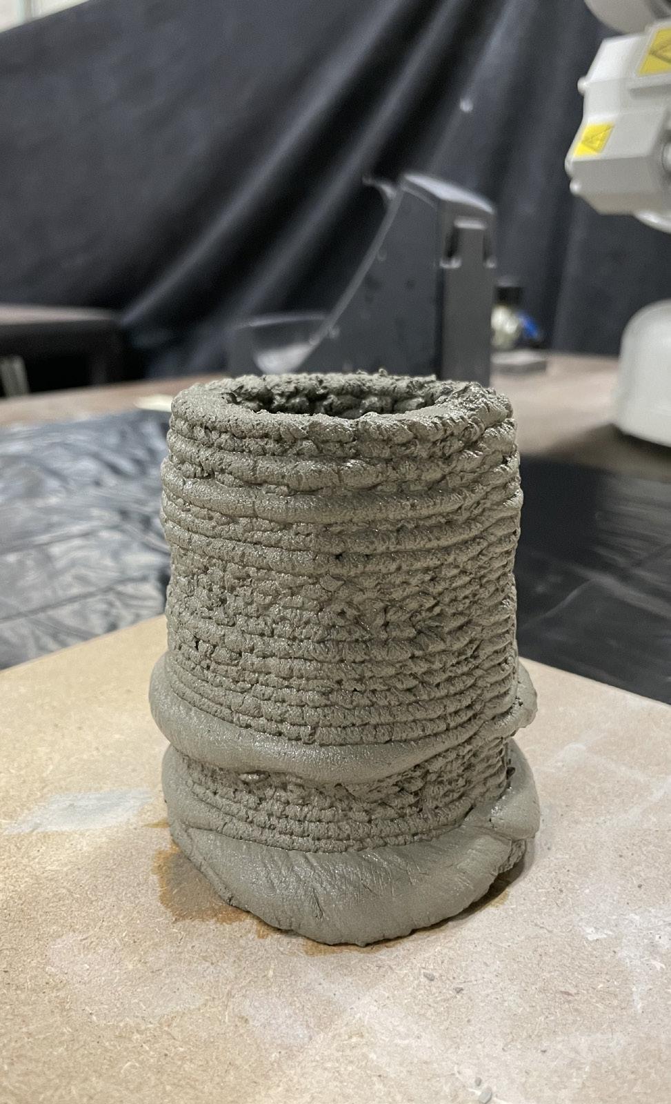
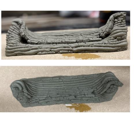
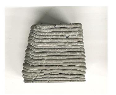
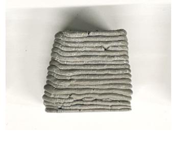
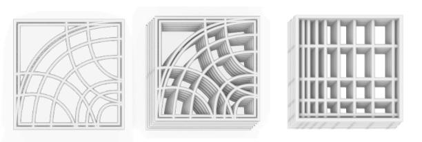
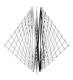
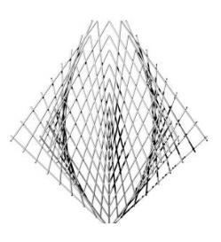
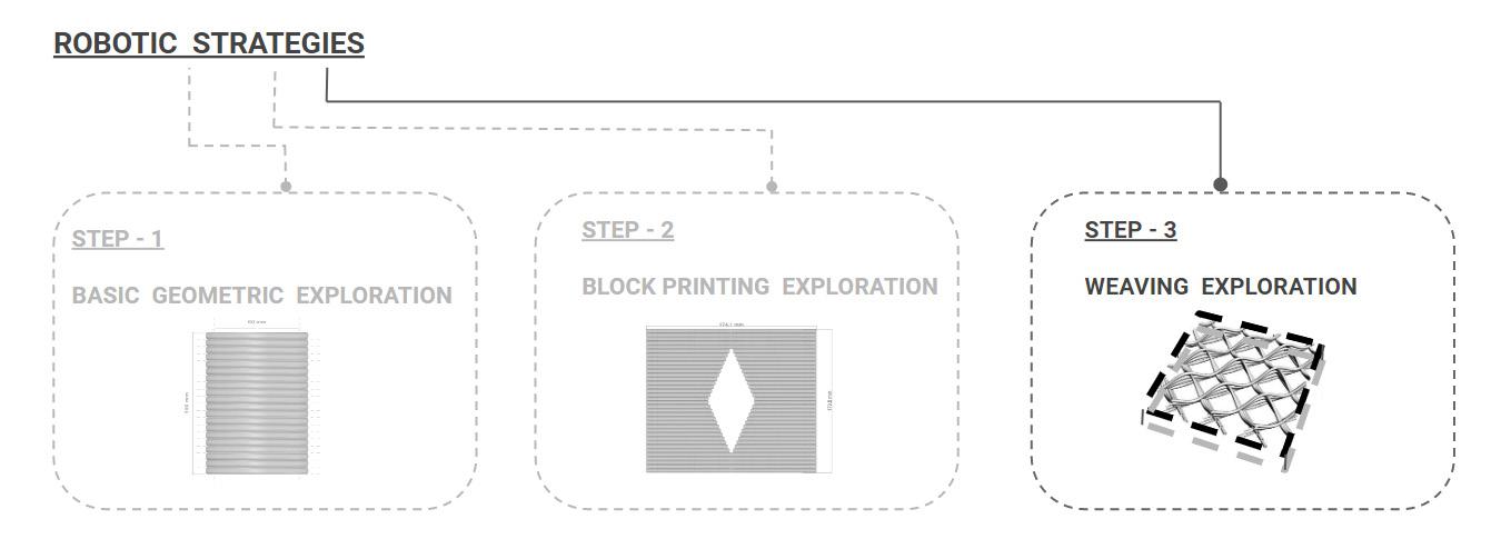
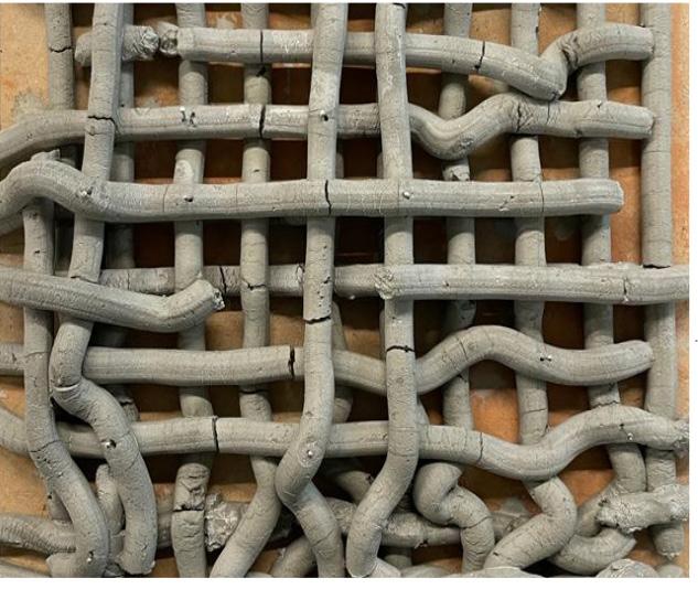
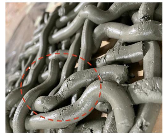
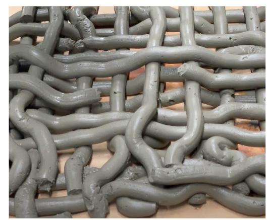
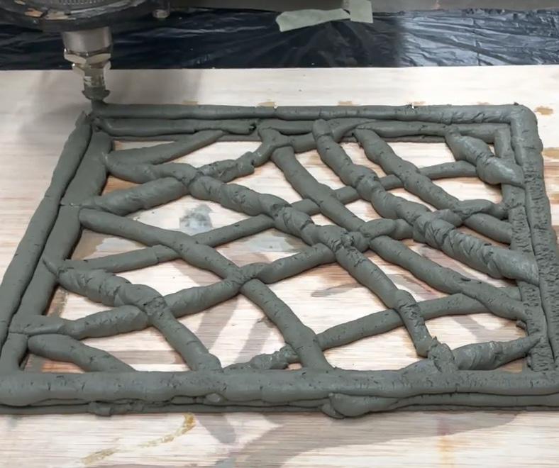
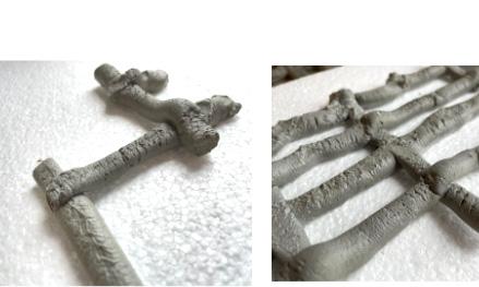
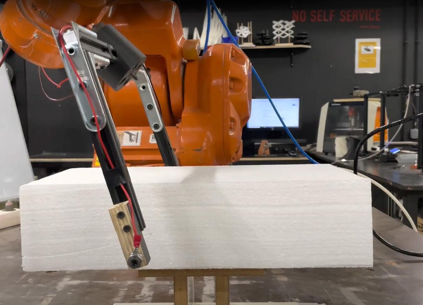
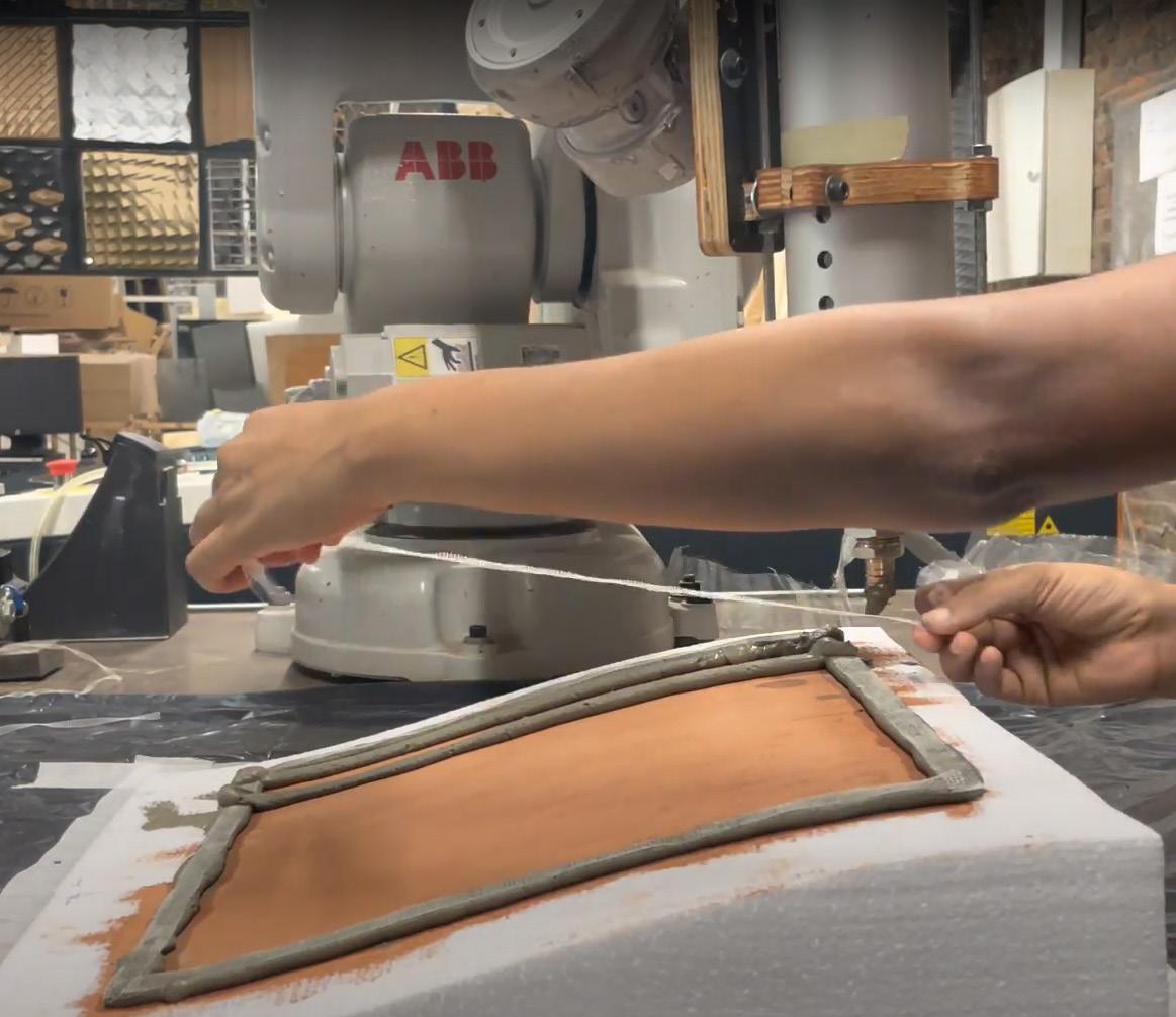
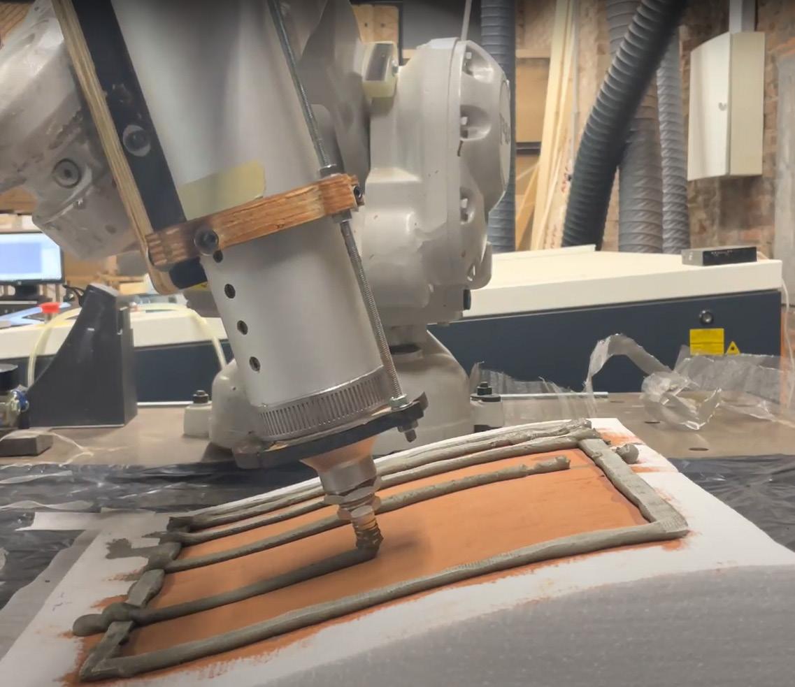
In this stage of fabrication, I explored a new technique called weaving. Weaving is the act of making something by combining different parts, in a complicated or skilled way. Using the weaving concept but with an additive manufacturing method, I would explore a technique to design a facade panel. As this technique is completely new for me so initially the main motive is to get a one-finish panel without collapsing. Prototypes incor porate techniques such as weaving as a means of fabricating panels that celebrate the inherent nature of the coil itself.
First strategy of printing is inspired from the state of art ¨WOVEN CLAY¨.
In this process, the extrusion was performed with a distance of 80mm between the printing base and the cartridge nozzle. After the pouring of the layer is finished, then just to explore the reinforcement, thin nails are inserted in some junctions to understand layer connectivity and their strength at the junction.
Pouring Layer - 1
• Layer Height - 5mm
• Layer Thickness - 10mm
• Water Ratio - 20%
• Sand Ratio - 0%
Pouring Layer -2
• Distance between printing base and nozzel - 80 mm
Pouring Layer - 3
Pouring Layer -4 -
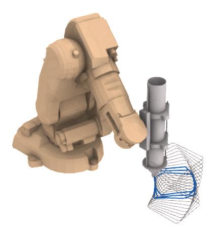
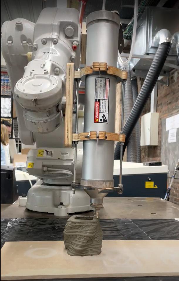
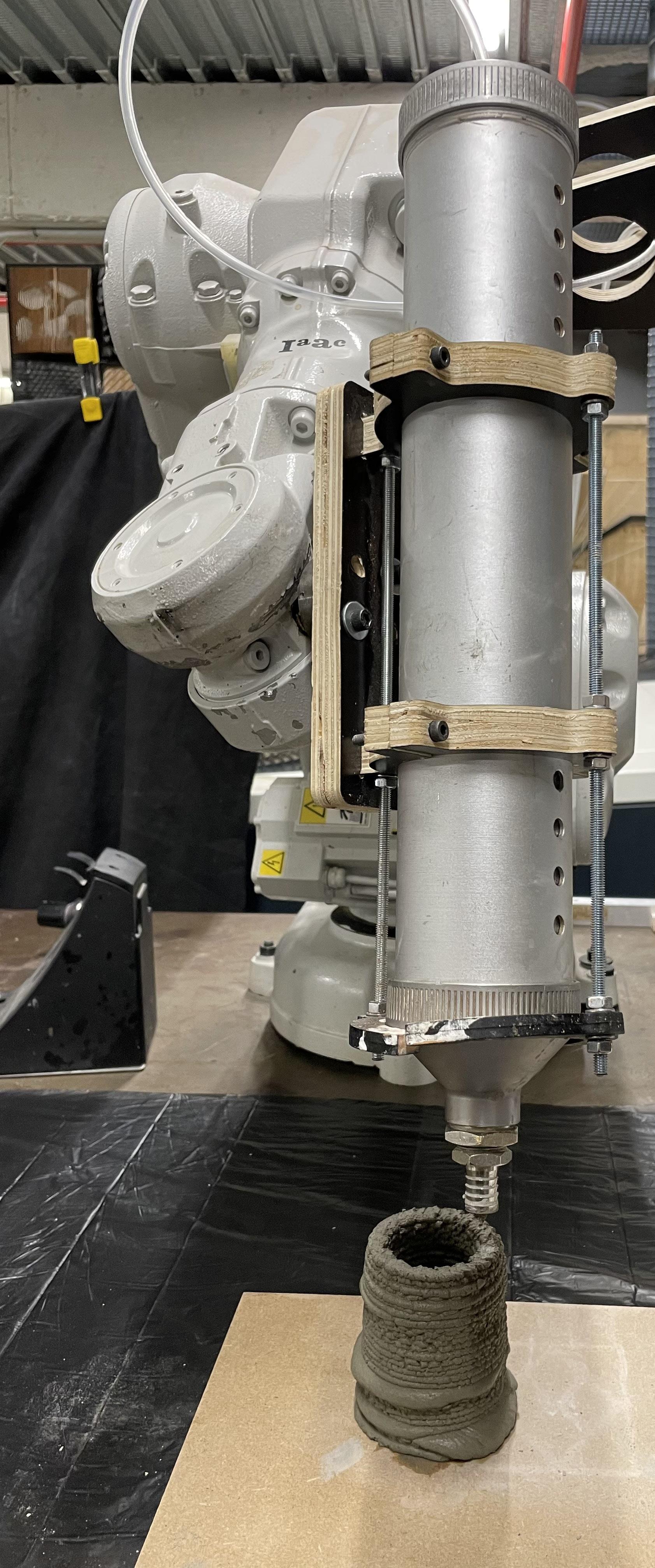
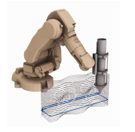
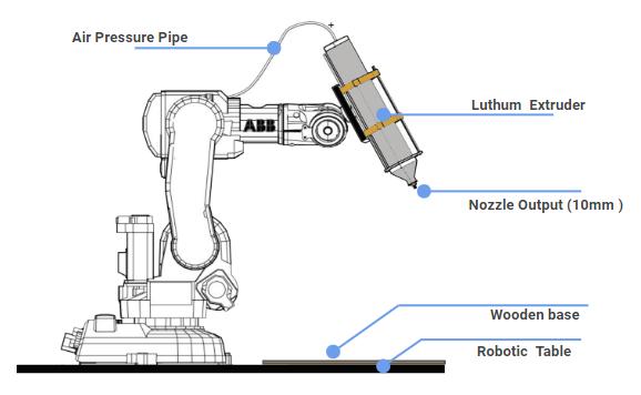
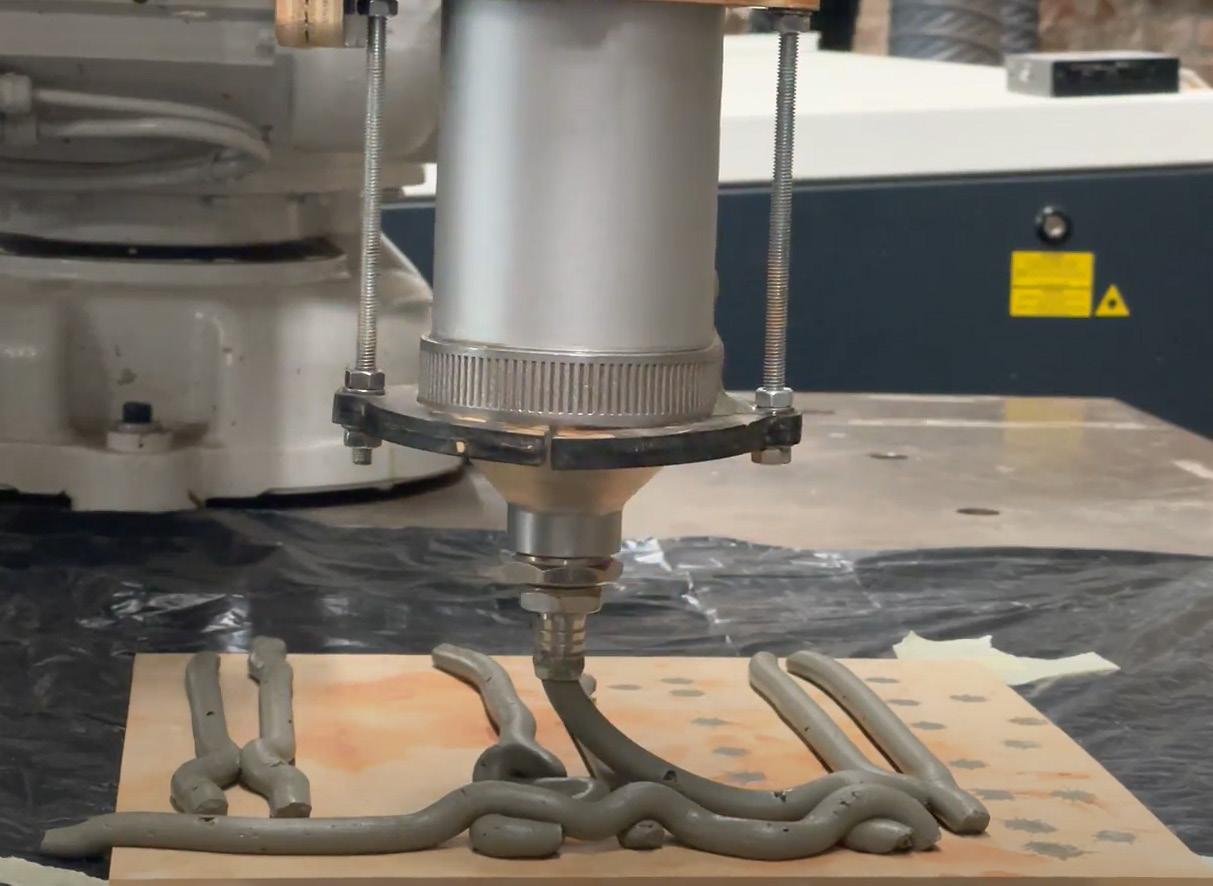
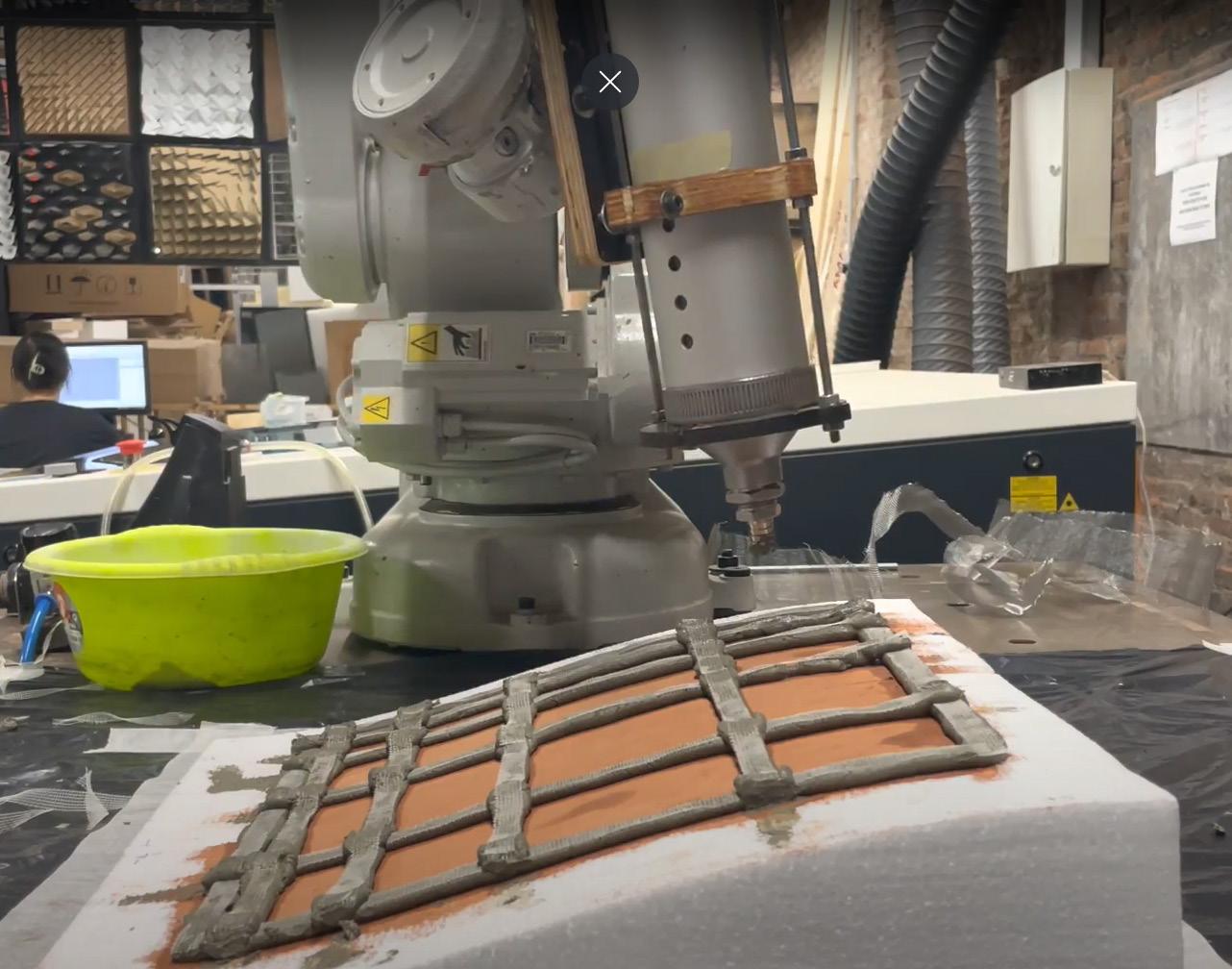
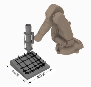
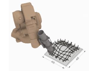
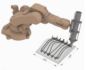
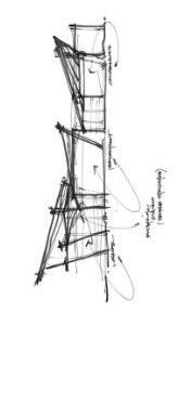
Panel Detail - Plan View Robotic Strategy ROBOTIC SETUP FOR PANEL PRINTING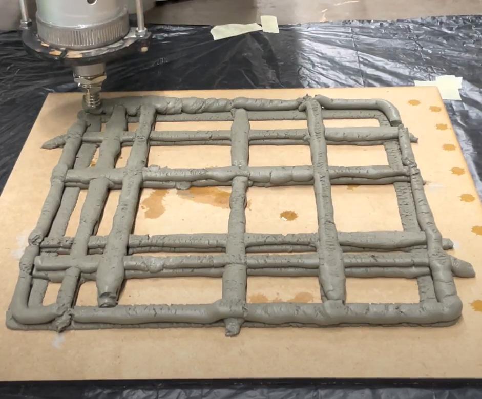
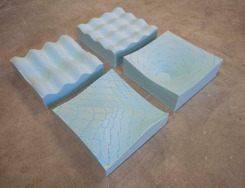
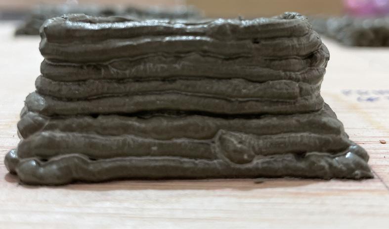
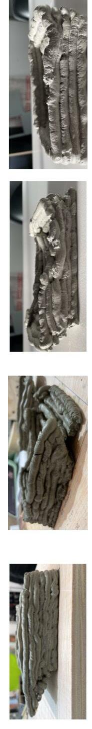
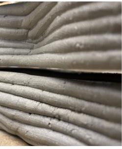
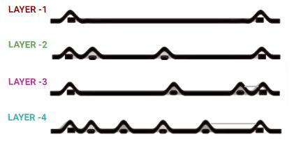
In this process, the extrusion was performed with the concept of extrusion in layers. Here, the exploration was done with straight lines and curve lines. The process is to print each set of layers and then move the nozzle 1 mm above to print another set of layers. In conclusion, the output with curve lines was fragile and cracked completely after cur ing. Further exploration was conducted in a straight line with different layering concepts.
• Layer Height - 5mm
• Layer Thickness - 10mm
• Water Ratio - 20%
• Sand Ratio - 0%
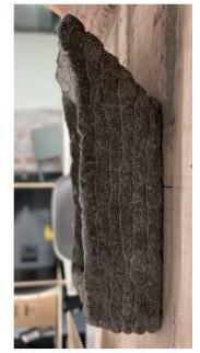
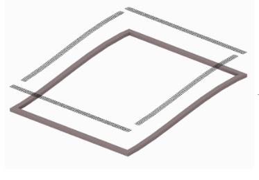
In the above exploration of strategies, there was an addition of a double layer in the periphery to support the internal layer. Printing strategy with the offset was performed to get depth and 50% visibility as the output, but it was a failed expriment as the offset distance was more. To summarize single layer and double layer concept was a successful attempt, which will be explored further.
 1) Single Layer
2) Double Layer
3) Print the layer with Offset
X axis moement both direction)
Plan Layer Concept
Plan Layer Concept
Plan Layer Concept
PLAN - Straight Lines Printing Strategy
PLAN - Curve Lines Printing Strategy
PROTOTYPE
PROTOTYPE
1) Single Layer
2) Double Layer
3) Print the layer with Offset
X axis moement both direction)
Plan Layer Concept
Plan Layer Concept
Plan Layer Concept
PLAN - Straight Lines Printing Strategy
PLAN - Curve Lines Printing Strategy
PROTOTYPE
PROTOTYPE
This conclusion is based on the straight-line exploration. In this process, due to shrinkage the layers we getting cracked and lose continuity. Also, the layers are getting cracked due to the dragging of material at the intersection junction.
On the other hand, there were some advantages of such a process which are, the bonding between layers was strong and the material ratio is preferable.
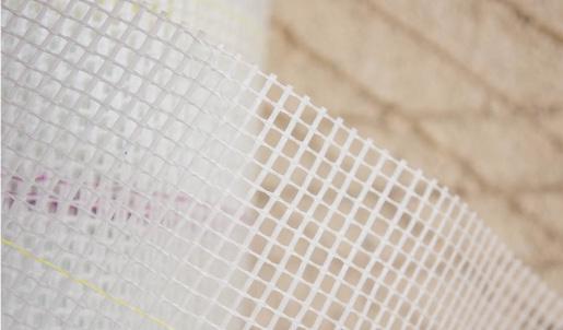
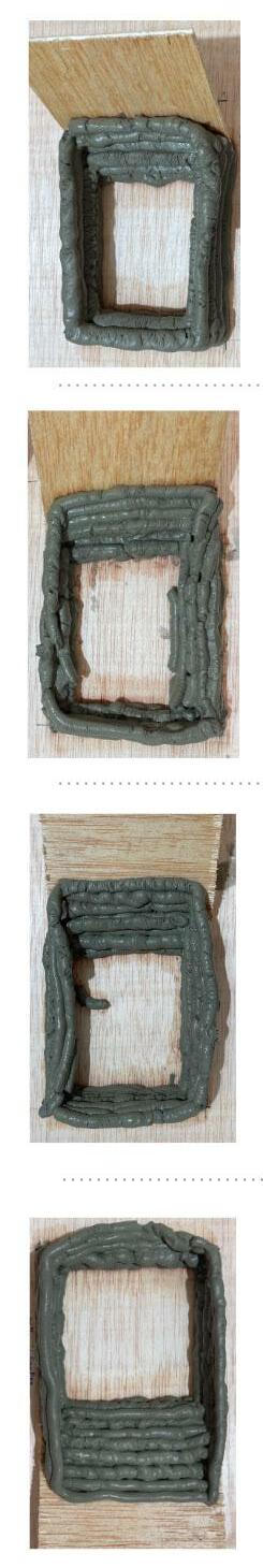
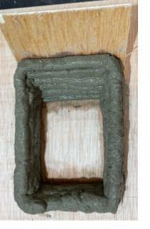
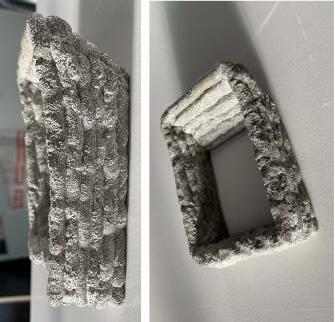
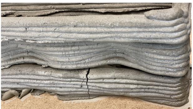
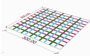
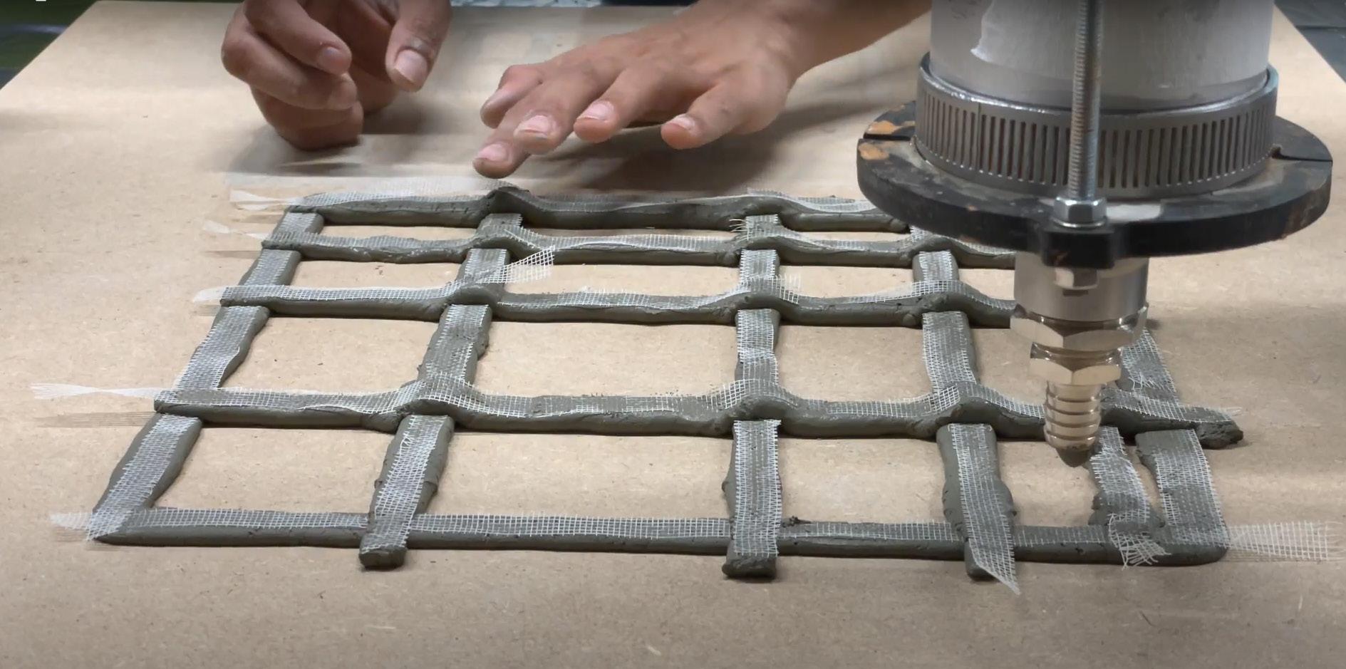
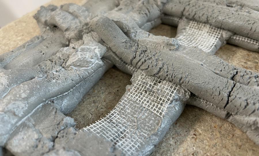
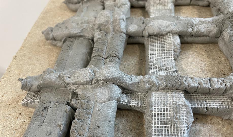
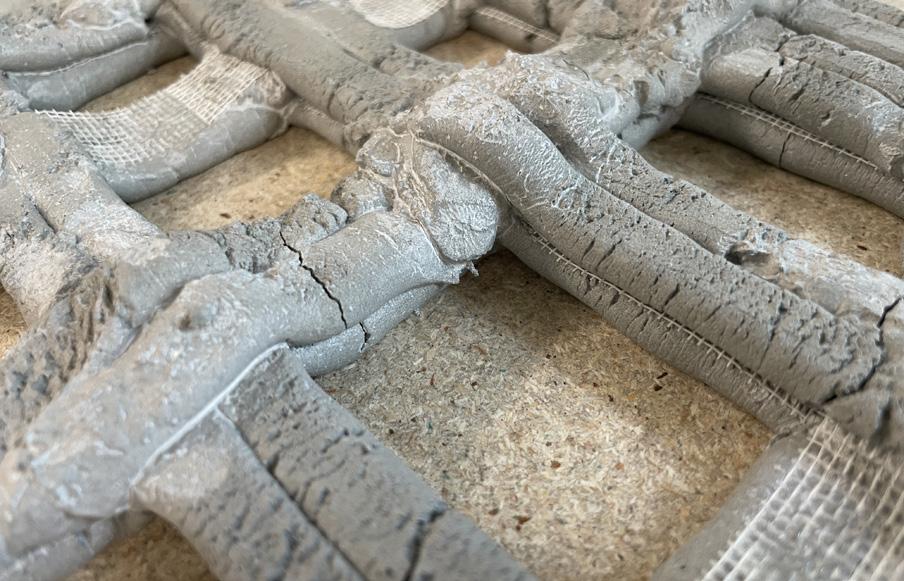
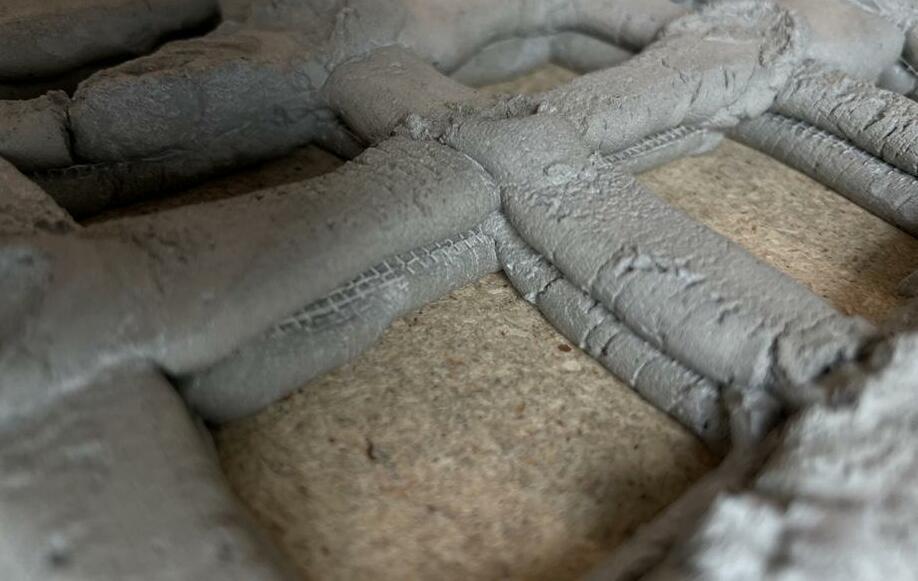
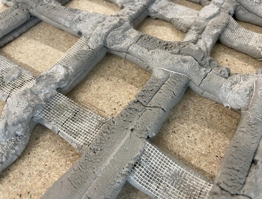
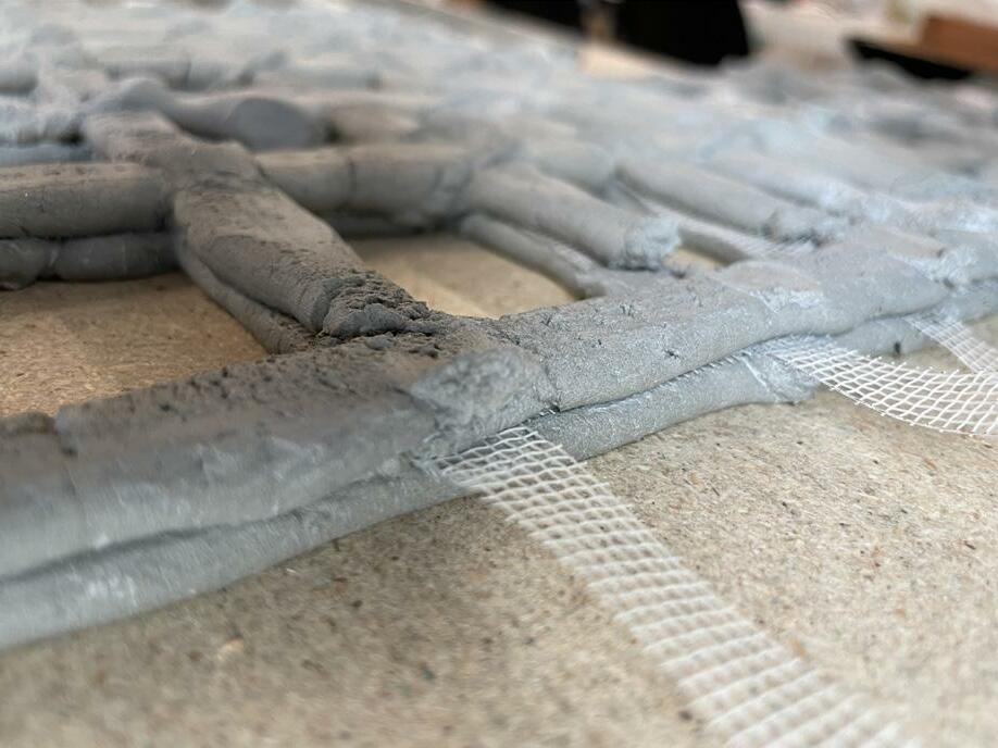
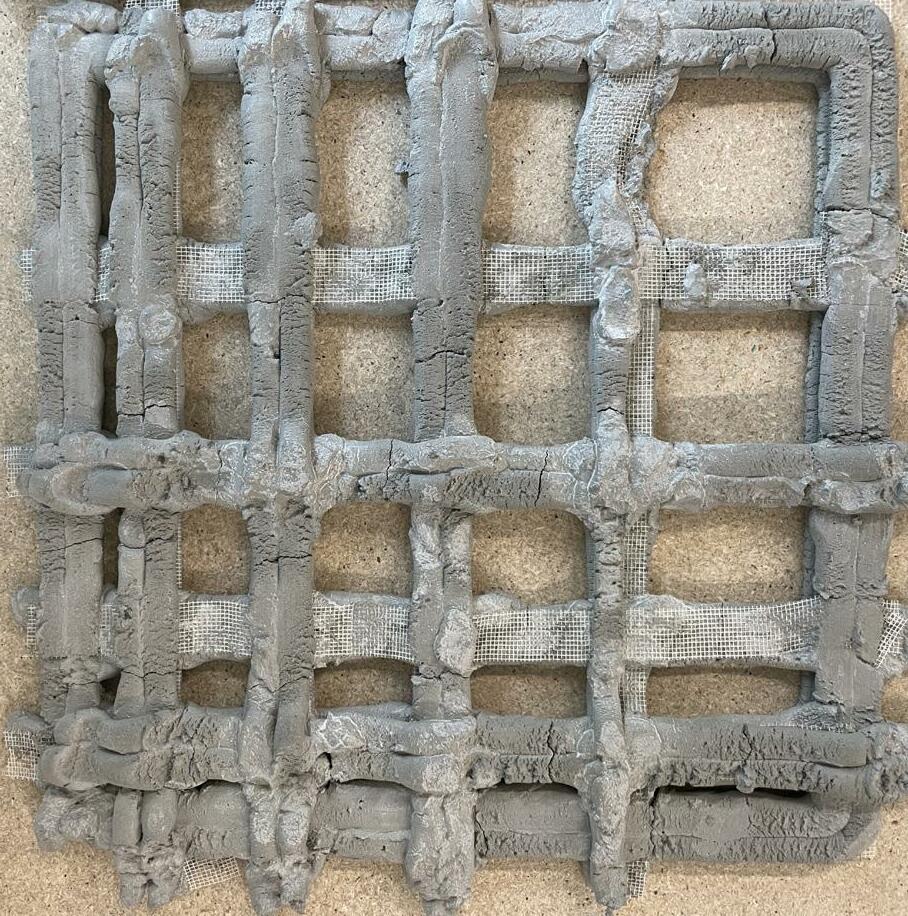
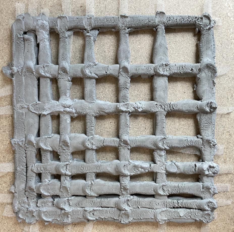
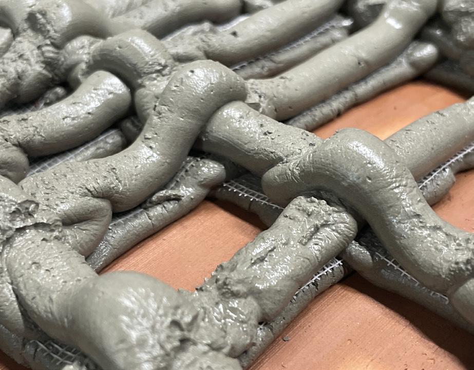
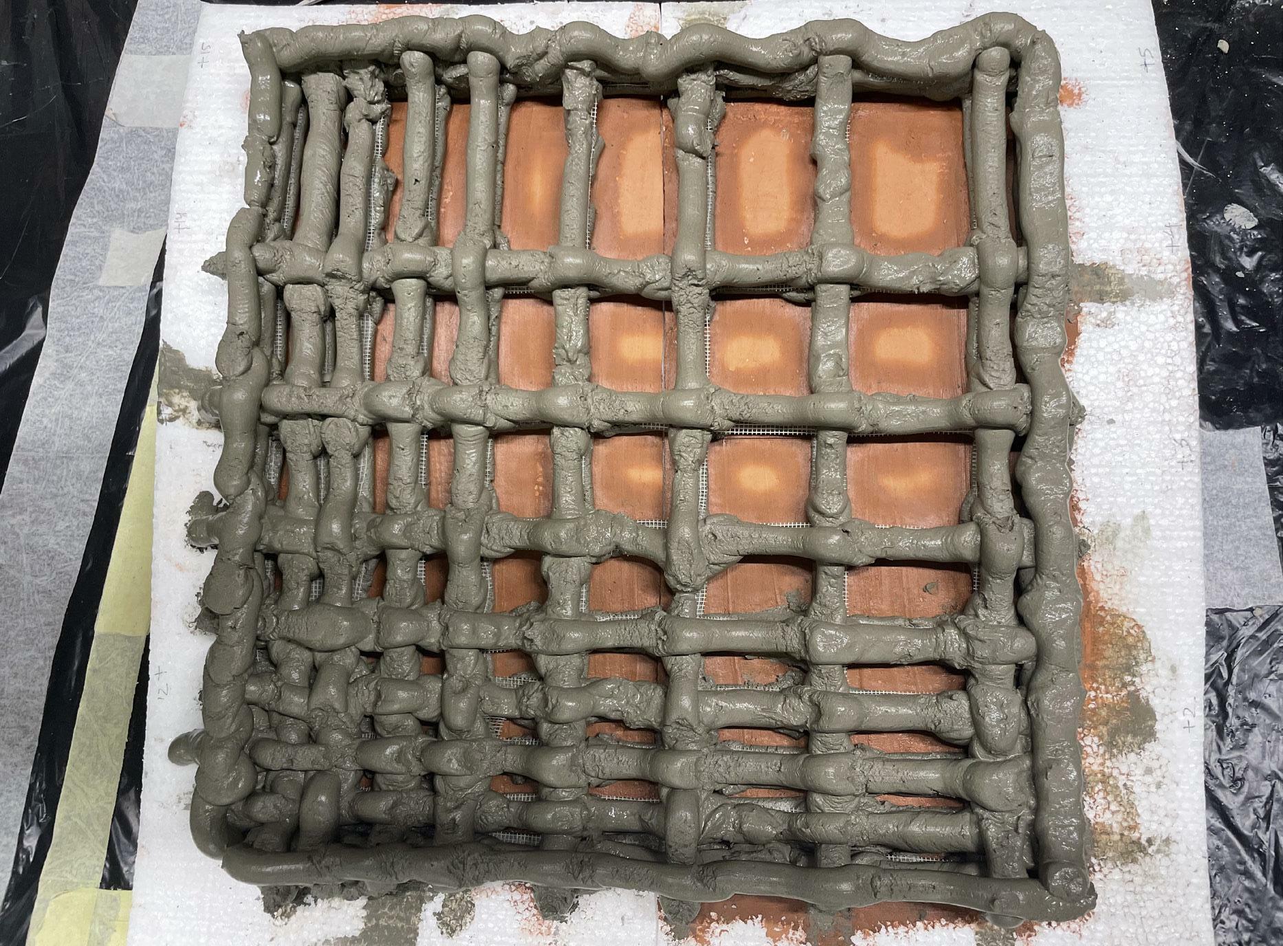
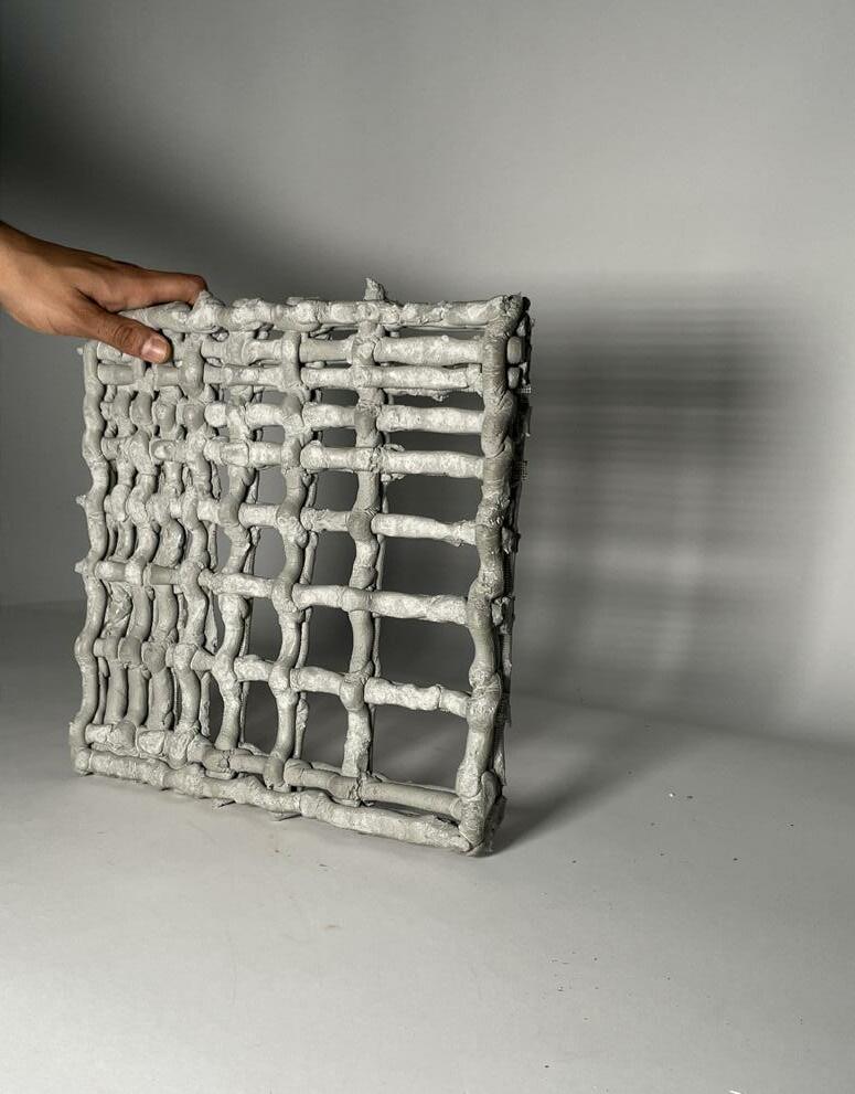
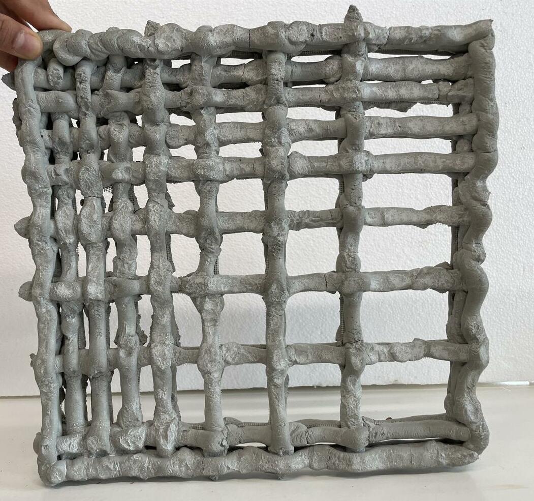
Furthermore, there was a slight change in printing strategies for exploration. As the material was dragging at the intersection, so to resolve that problem I add a bump or Z-axis offset at every intersection point. Additionally, laying a layer of grid mesh as a reinforcement to resolve the problem of crack due to shrinkage at every layer set.
In this process, the extrusion was performed with mesh reinforcemnt and creating a curl at the intersection. The exploration was done with a single layer set and a double layer set to understand the connection between the 2 layers after being cured, material viscocity under, segregation of water under a pressure-based extruder and the weight of the panels.
• Layer Height - 5mm
• Layer Thickness - 10 to 20 mm
• Water Ratio - 22%
• Sand Ratio - 5%
• No. of Layers - 2 sets of Layers
• Reinforcement - Yes
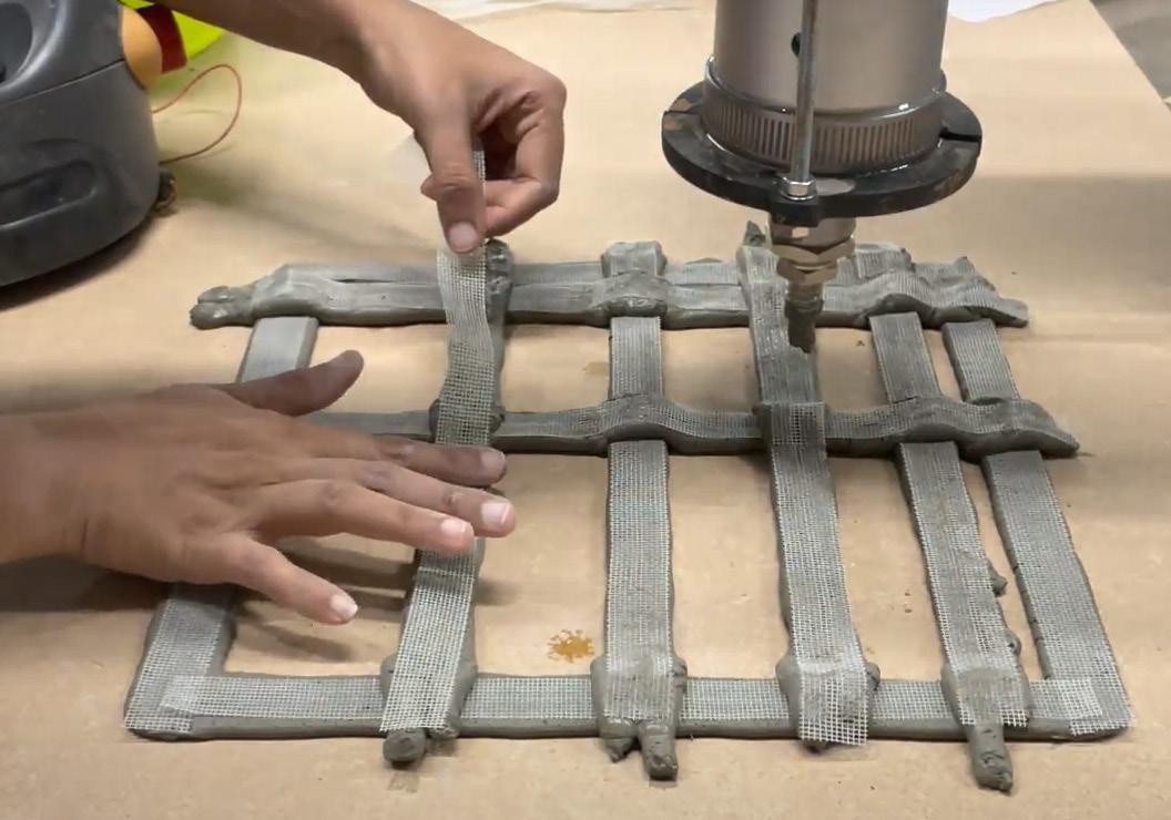
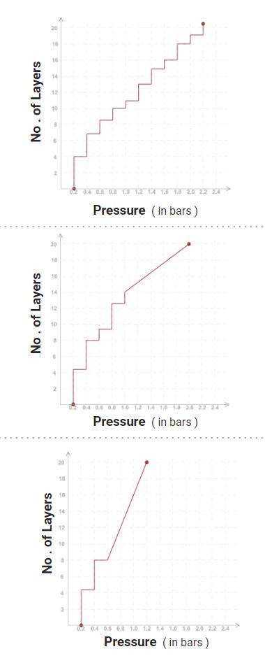
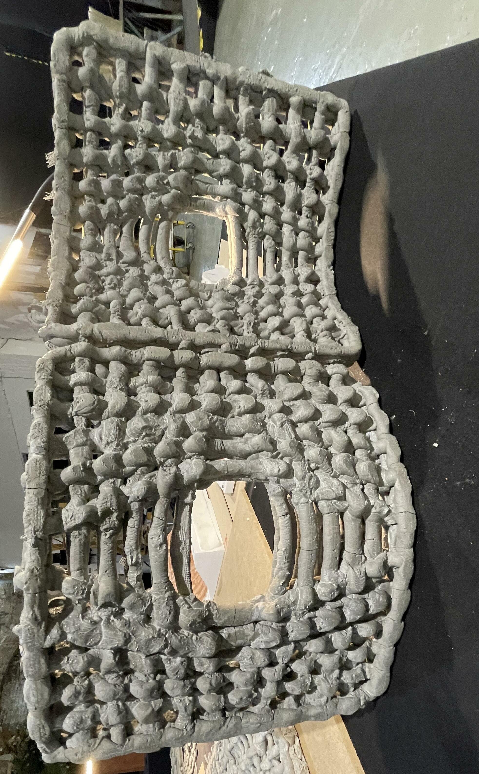
In conclusion, due to mesh reinforcement crack formation reduction by 85% and also the material consistency is exact consistency reqired for printing panel without any accer lant. Here, the time between mixing and printing is exact 10 minutes and no segregation occurs, whereas the pressure bar remains between 0.5 bar to 3 bar maximum.
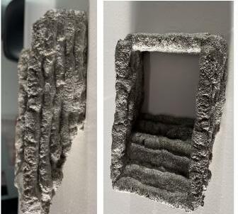
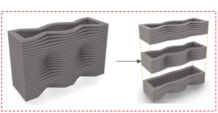
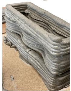
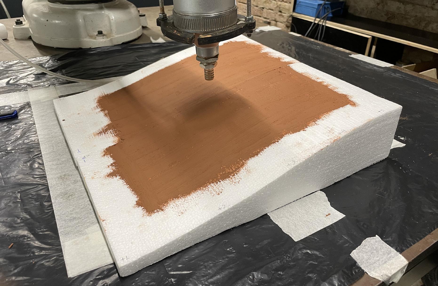
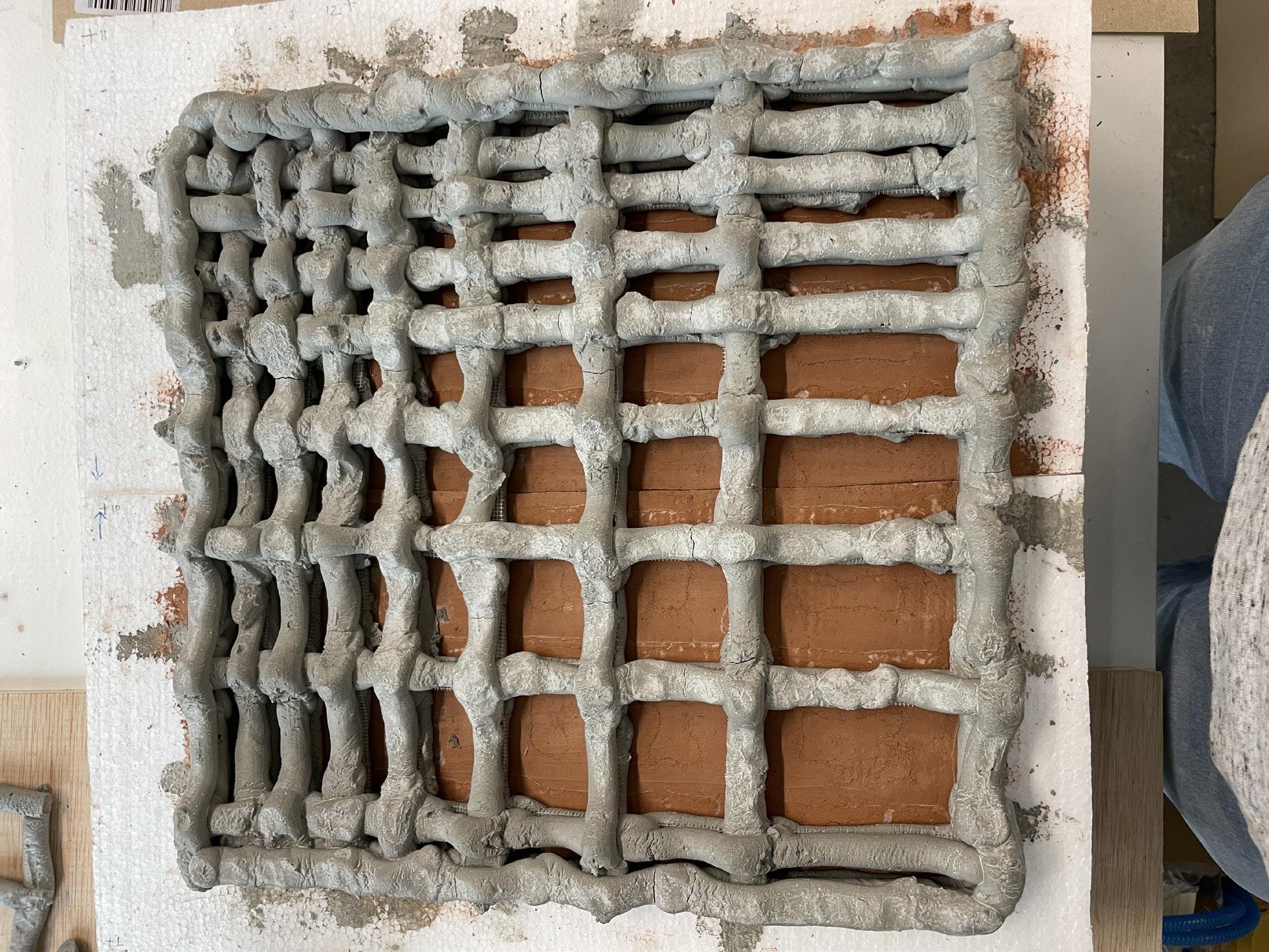
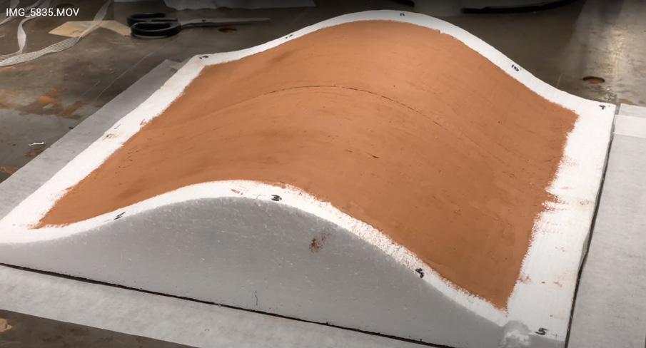
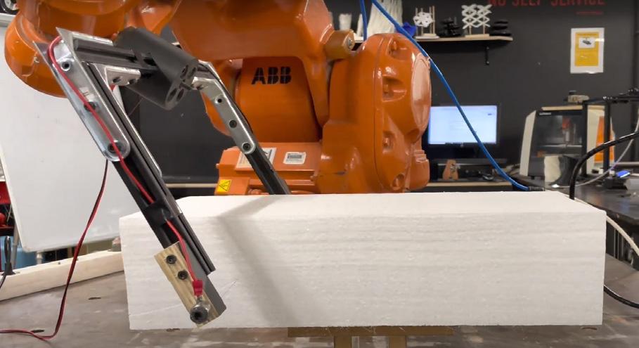
In this process, the extrusion was performed with mesh reinforcemnt and in a non-planer manner, where EPS block are used as base support. In this strategy robotic process is used in 2 ways: i) for extrusion & ii) for hotwire cutting of EPS blocks.
However, the whole process is explained below the detailed process for extruding the non-planer panels with support.
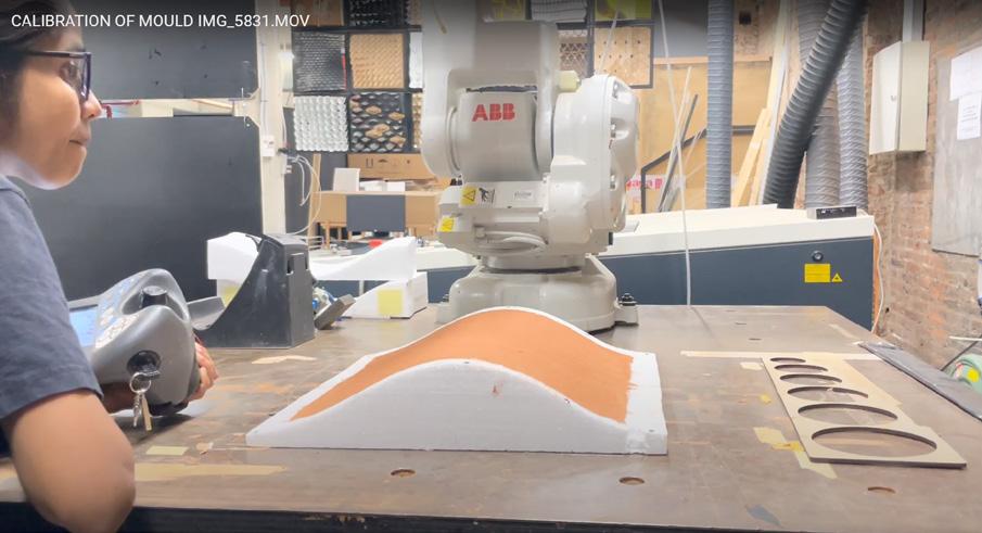
In the below give flowchart there is a step to recalibrate the eps block because after the process of robotic hotwire cutting there was a 3 - 5% difference between the digital block for printing and the physical block for printing.

During the process of extrusion, it was difficult to extrude directly on the eps block. Due to its porous behaviour, the extruded concrete material was stuck to the base which result in breaking up the panel. So to resolve the issue, the eps base top was coated with red clay, which gives a rough but less porous base to extrude.
 ROBOTIC FABRICATION - STRATEGY ( 4 ) OUTPUT
EXTRUSION & REINFORCEMENT
ROBOTIC PRINTING PROCESS
ROBOTIC FABRICATION - STRATEGY ( 4 ) OUTPUT
EXTRUSION & REINFORCEMENT
ROBOTIC PRINTING PROCESS
• Layer Height - 5mm
• Layer Thickness - 12 mm
• Water Ratio - 22%
• Sand Ratio - 5%
• No. of Layers - 2 sets of Layers
• Reinforcement - Yes
• Panel Porosity - 10 - 30 %
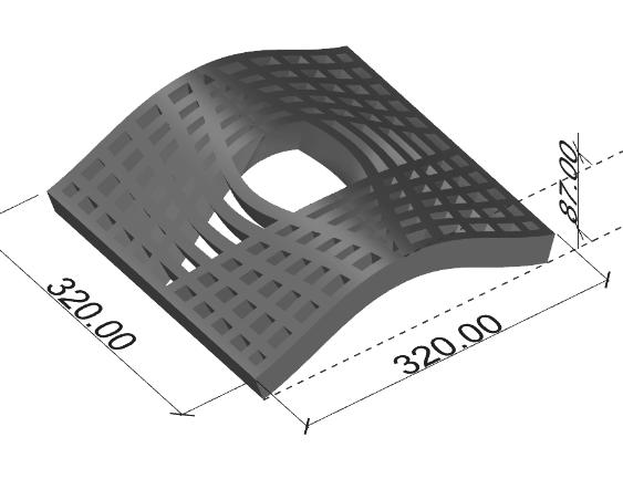
 NON-PLANER GEOMETRY GEOMETRY
DIGITAL FINAL OUTPUT
PLAN - DIGITAL PANEL DESIGN
NON-PLANER GEOMETRY GEOMETRY
DIGITAL FINAL OUTPUT
PLAN - DIGITAL PANEL DESIGN
• Layer Height - 5mm
• Layer Thickness - 12 mm
• Water Ratio - 22%
• Sand Ratio - 5%
• No. of Layers - 2 sets of Layers
• Reinforcement - Yes
• Panel Porosity - 30 %
 COCEPTUAL LAYER SECTION
ROBOTIC FABRICATION
COCEPTUAL LAYER SECTION
ROBOTIC FABRICATION

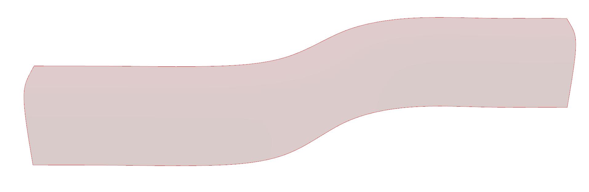
WEAVING PANEL COMBINATION
- GEOMETRY 1
WEAVING PANEL COMBINATION
- GEOMETRY 2
In comparison with the previous exploration in Concrete 3D printing, this paper pro posed the design of 3D printed precast components is used on a large scale for common buildings. On the contrary, previous experiences focused on special components for un common constructions without considering the aspects of performance and sustainability involved in large-scale applications. An important characteristic of the proposed design concerns the printability and possible optimization of the extrusion path.
Series of full-scale prototypes will be focused on a specific building application, whereas this research’s main motive was to resolve the seemingly conflicting nature between the inherent mutability of the concrete material and the high level of control granted by robotic fabrication processes.
This research opens up new perspectives and possibilities for to use of 3D printing for the prefabrication of precast components for building construction. Future research will develop a real-scale prototype to be applied in an existing structure study to take a fur ther step towards the use and social acceptance of this innovative construction technique. ALso, panels will be further explored in different scalable units as per the optimization result.
1. BESIX 3D - largest 3D printed concrete façade. ( news/besix-3d-prints-largest-concrete-facade-in-the-world)https://www.besix.com/en/
2. 3D-PRINTED HOUSING IN THE FACE OF CLIMATE CHANGE ( https://2ser. com/3d-printed-housing-in-the-face-of-climate-change/)
3. 3D printing for construction and architecture projects: The Ultimate Guide construction-and-architecture/)https://www.sculpteo.com/en/3d-learning-hub/applications-of-3d-printing/2022
4. 3D-printing in construction: where are we now? ( case-studies/3d-printing-in-construction-where-are-we-now/https://www.inexhibit.com/)
5. Influence of periodic texture profile and parameters for enhanced light ab sorption in amorphous silicon ultra-thin solar cells (optica.org)
6. RESEARCHERS DEVELOP NOVEL TOPOLOGY OPTIMIZATION TECHNOLOGY FOR LARGE-SCALE 3D PRINTING KUBI SERTOGLUJUNE 2021
7. OPEN-SOURCE ML ALGORITHM TO ACCELERATE THE DISCOVERY OF NEW 3D PRINTING MATERIALS (https://3dprintingindustry.com/news/opensource-ml-algorithm-to-accelerate-the-discovery-of-new-3d-printing-mate rials-198064/)
8. 100 3D PRINTING EXPERTS PREDICT THE FUTURE OF 3D PRINTING IN future-of-3d-printing-in-2030-167623/)(https://3dprintingindustry.com/news/100-3d-printing-experts-predict-the-2030
9. POLISH RESEARCHERS EXPLORE AUTOMATION FOR 3D PRINTED BUILDING.
10.THE FUTURE OF CONCRETE PRINTING WITH IMPRIMERE AG.
11.CONCRETE 3D PRINTER BREAKS DOWN WALLS OF TRADITIONAL CONSTRUC TION TYLER KOSLOWOCTOBER 28TH 2015
12 . 3D Printing: ensuring manufacturing leadershipin the 21st century (PDF)
13 . 3D Printing with Concrete: Impact and Designs of Structures (PDF)
14 . Coupling Parametric Design and Robotic Assembly Simulation to Generate Thermally Responsive Brick Walls (PDF)
15 . Hambach, M. and D. Volkmer. 2017. “Properties of 3D-printed Fiberreinforced Portland Cement Paste. Cement Concrete Composites
16 . Zeeshan, A. F. (2016). “Design Considerations Due to Scale Effects in 3D Concrete Printing.” In Parametricism Vs. Materialism: Evolution of Digital Technologies for Development; 8th ASCAAD Conference Proceedings, 115-124.
17 . Developing an integrated 3D-printed façade with complex geometries for active temperature control Maria Valentini Sarakinioti, Michela Turrin, Thaleia Konstantinou, Martin Tenpierik, Ulrich Knaack. (PDF )
18 . The impacts of fabrication systems on 3D concrete printing building forms Shuyi Huang, Weiguo Xu*, Yuqian Li School of Architecture, Tsinghua University, Beijing, China
19 . Robotic Technologies in Concrete Building Construction: A Systematic Review, M. Gharbiaa , A.Y. Chang-Richardsa , and R.Y. Zhongb.
20 . EVOLUTION OF GEOMETRIC PATTERNS IN ISLAMIC WORLD AND A CASE ON THE JALIS OF THE NAULAKHA PAVILION IN THE LAHORE FORT.