
ARCHITECTURAL PORTFOLIO LEKHA GAJBHIYE

September 2018 - March 2019
SOFTWARELANGUAGE
Adobe Premiere Pro - Video Editing Digital Fabrication
• Upheld company design best practices as well as local requiremnets and national building codes.
• Participated in architectural compitition - National Association of Students of Architecture (NASA, India) . (for 3 years).
• Put together project documentation and submittal packages.
February 2017 - December 2017
April 2019 - May 2020
• Worked on various architectural and interior drawings with respective 3d working.Even partici pated in site visit to ongoing projects for measurements, material study and documentations.
• Interaction with clients, projects funding alumna and working labourer.
• Participated in Parametric Facade Design Workshop , Delhi 2016
• Majorly worked on architectural drawings, electrical and plumbing drawings.
Seeking full-time entry-level possibilities to broaden my skills while facilitating company growth and assisting me in growing further with the organization.
• Completed formal design intent and construction documentation of a residential project.
• Drafted design objectives and system design documents.
Higher Secondary School Certificate , ( Indian School Certificate - 12th grade).
Architect - Freelancer, Nagpur, Maharashtra , India.
Jr. Architect - Design Edge Architects , Nagpur, Maharashtra , India.
Chanda Devi Saraf Nagpur , Maharashtra , India.
3 months - Internship.
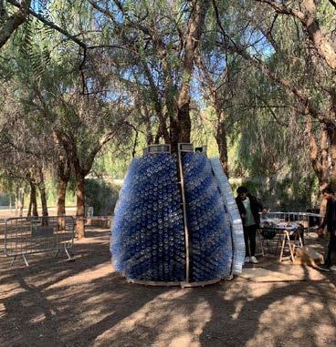
• Participated in real scale project (LLUM Barcelona )
Seventh Day Adventist High School , Nagpur , Maharashtra , India. Graduated - 2008 SKILLS
• Collaborated with clients to facilitate involvement and effectives communication between project parties.
3D - VISUALIZATION & RENDERING.
QGIS Houdini - Beginner BIM Grasshopper- Beginner
Bachelor of Architecture , ( 5 years).
LEKHA GAJBHIYE 440013 , Nagpur, Maharashtra , India. 08018, Barcelona, Spain ( currently reside)
• Monitored design processes from the conceptual phase through construction.
ENGLISH - C1 HINDI -
+34lekha.g111992@gmail.com-632931603
An organised person is able to employ time management and organizational skills in a variety of settings.
• Created oral and written presenatations for projects designs and proposals.
AdobeSketchup(Photoshop & Indesign)
• Participated in Mud and Bamboo Architecture , Mumbai 2012 • Participated in 3rd Global Congress on Sickle Cell Disease, Bhuneshwar, Odisha, India 2017.
• Also worked on proposal drawing, renovation and execution work interior detailsand some govern ment - sanctioned drawings.
• Crated oral and written presenattions for project designs and proposals.
Python - Grasshopper - Beginner CIRRICULUM
Graduated - 2011 Indian Certificate of Secondary Education. ( 10th grade ).
• Annual School Dance Programme 8th grade.
RhinoSPANISH-C1A1Architectural & 3D GrasshopperAutocadArchitecturalMicrosoft(Word,Presenation & Excel) Corel Draw
RoboticsVirtualReality
Jr. Architect - Hiten Sethi Architect , Navi Mumbai , India.
• Participated in Inter- College Swimming Competition, Mumbai 2015.
Rachna Sansad - Academy of Architecture , Mumbai , India. June 2011 - October 2016
EDUCATION Master in Advanced Architecture , ( 2 years).
• Participated in Biomimetic Design Workshop Delhi 2020.
Institute of Advanced Architecture Barcelona , Spain. October 2020 - June 2022
• Olympia Exam in 8th grade.
• Participated in Kala Ghoda Festival , Mumbai 2012
EXPERIENCE
Acquiring specialized talents at each level and giving forth my best effort to work for the company’s overall stability and prosperity.
Intern Architect - Ashok Mokha Architects , Nagpur, Maharashtra , India.
• Worked within Autocad, Rhino and some basic Revit integration to complete design, model renderings and specification details.
• Presented 3d design proposal to the client as part of overall design team for the projects.
• Participated in some architectural compitition and software developemt class.


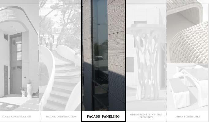
1CONTENTS ) THESIS RESEARCH - CONCRETE 3d PRINTED PANELS. 4 - 15 - After Gaudi .............................................................................................................................. 18 - 23 - Design Development of 5 Star Hotel - Manali ............................................................... 24 - 29 - Panvel Airport Building - Facade Development .......................................................... 30 - 38 - Savartri Kidney Care Hospital ........................................................................................... 40 - 41 - Agricultural College Proposal , Madhya Pradesh, India ............................................ 42 - 47 - Digital matter ( Carbon copies) ......................................................................................... 50 - 59 - Hotwire Cutting ........................................................................................................................ 60 - 63 - Robotic Tufting ......................................................................................................................... 64 - 67 4) OTHERS 2) DESIGN PROJECT 3) ROBOTIC FABRICATION - LLUM ......................................................................................................................................70 - 73 - ROBOTIC Clay Prining ...........................................................................................................74 - 75 - PYTHON - Green Noise ........................................................................................................... 76 - 79
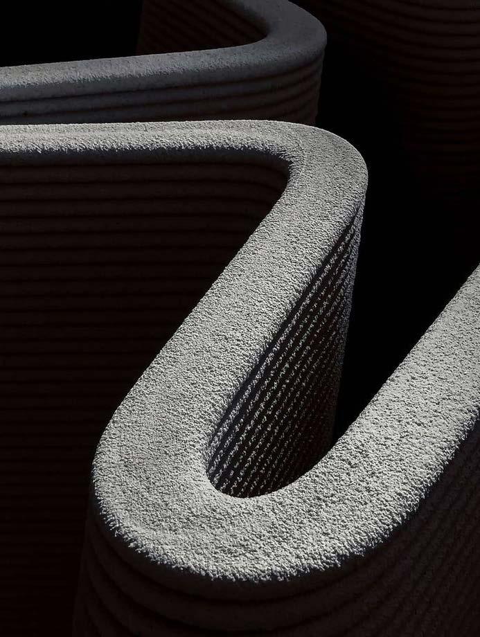
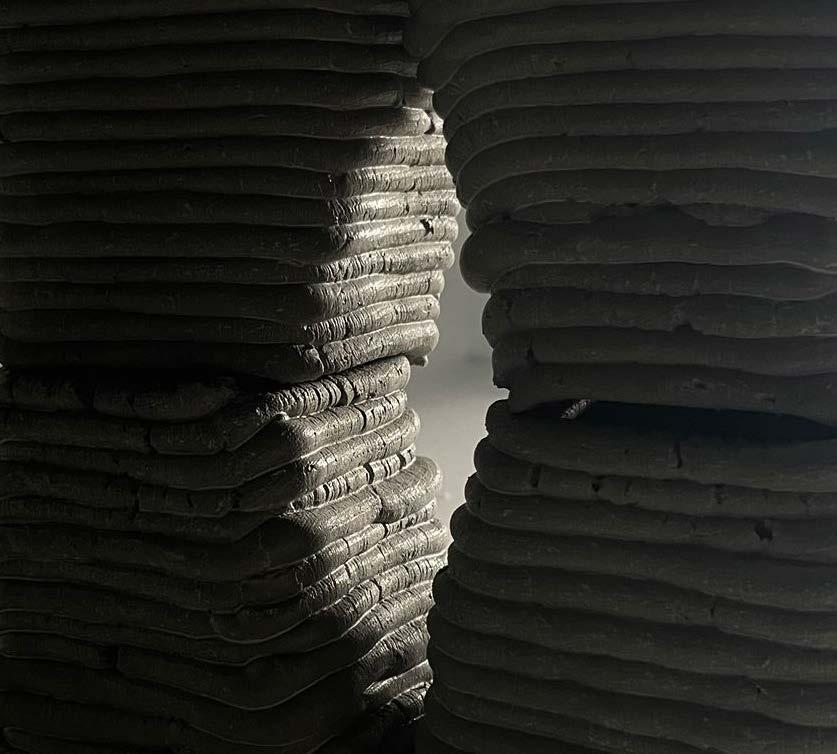
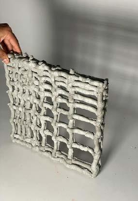
CONCRETE WEAVING
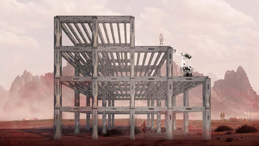
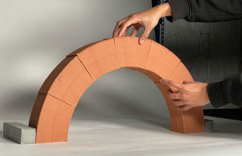
Concrete 3D printing is revolutionizing building sites all over the world by delivering high-quality homes quicker, better, and cheaper. The thesis investigates layer printing of cementitious materials and explores for efficient methods for printing complicated geometries while enhancing aesthetic and environmental quality.
MAA02 - THESIS RESEARCH
Also, thesis focuses on the advanced systems integration between conventional building perfor mance design and digital additive manufacturing, which enables the printing concrete industry to develop and construct cutting-edge architectural solutions with added value for end users in energy savings.
Later on, emphasize on the role of morphology for environmental adaptation, where distinct mor phologies, corresponding processes and potential are applied to buildings performance.
6 7
CONCRETE 3D PRINTED PANELS
The main focus of my thesis is to look mainly in facade construction by concrete 3D printing and create a performative facade system for the developing structures.
Location :- Institute of Advanced Architecture
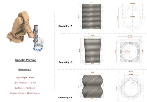
The project's objective is to create and test robotic 3D printing technologies that allow for the cus tomization of high-resolution parts. Research evolves along with three main thrusts of work mate rials, systems, and design.
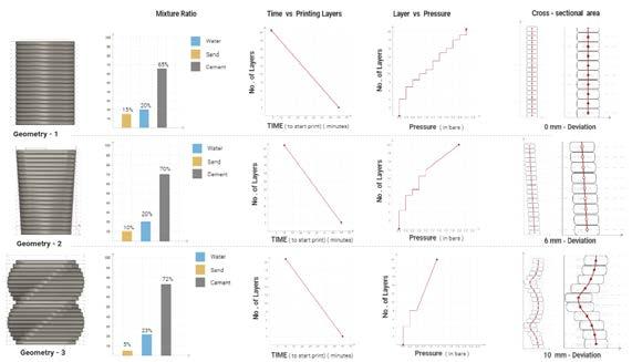
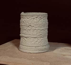
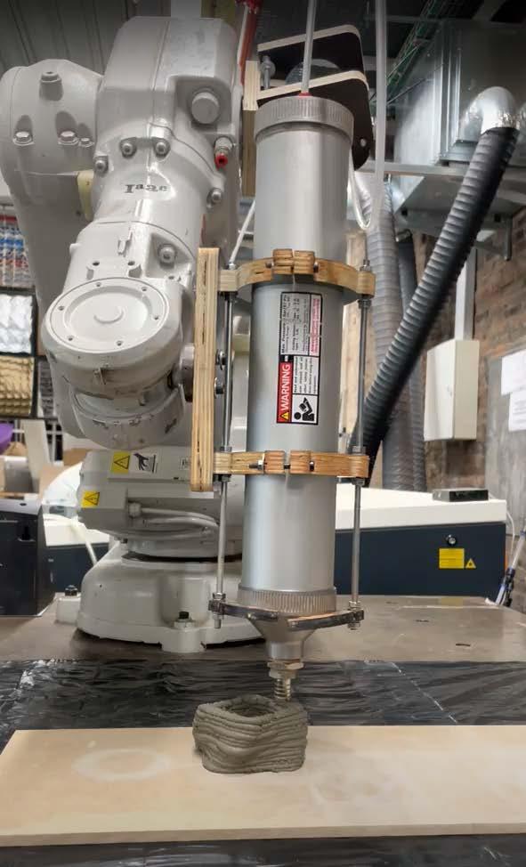
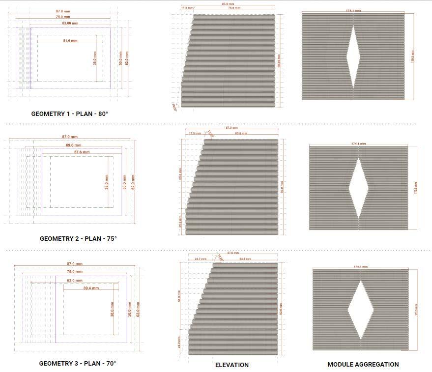
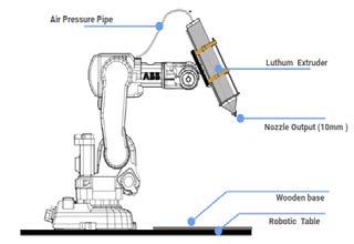
1) MATERIAL EXPLORATION 1 - A. MATERIAL COMPOSITION 1 -B GEOMETRIC ACQUAINTANCE GEOMETRY - 1 GEOMETRY - 2 GEOMETRY - 3 1 - A. MATERIAL RATIO RESULTS ROBOTIC SETUP PISTON & PRESSURE BASE EXTRUDER 8 GEOMETRY - 3 PRINTING EXPLORATION WITH BASIC GEOMETRIES


3)
FINAL DESIGN STRATEGY
Variation in Panel Design and thickness based on Radiation Analysis Panel Aggregation Composition CONCEPTUAL OUTPUT FOR FACADE PANELS
2) WALL PERFORATION EXPLORATION
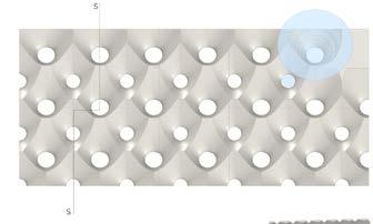
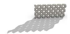
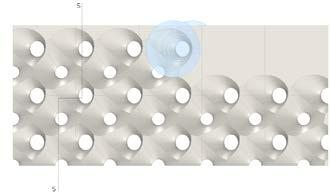
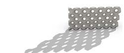
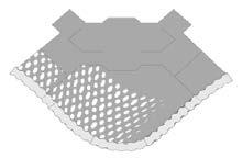
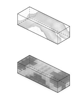
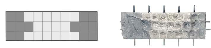
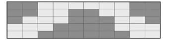
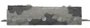
After understanding the constrain for the robotic printing the process was changed to print the wall The wall was further divide into grid and tried to print an opening with concpet of block pattern. Various size of openings were explored with some specific angles, not less than 60 degree
PANEL STRATEGY to manipulate light. - 70% of solar need - Maximum Visibility - Single Layer Panel - 30 - 40 % of solar need - 50% Visibility - Some area Double Layer Panel - 10% of solar need - Private Space - Double Layer Panel
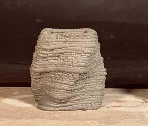
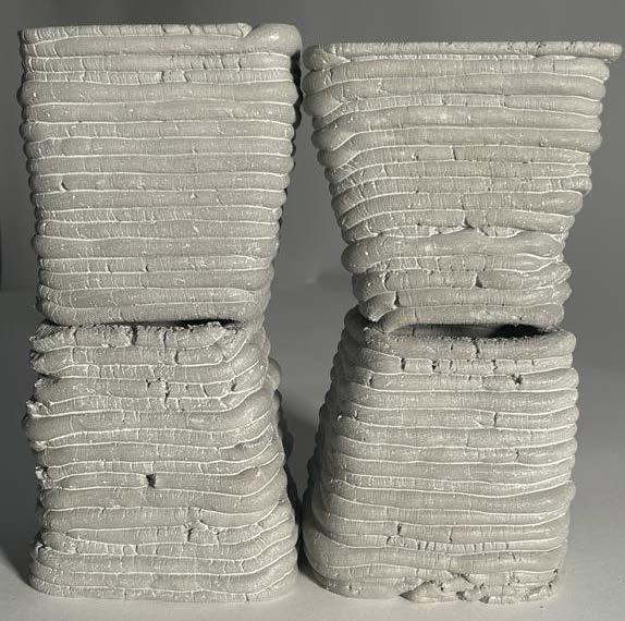
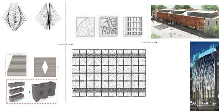
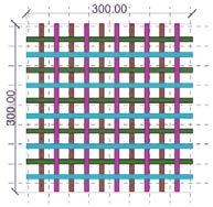
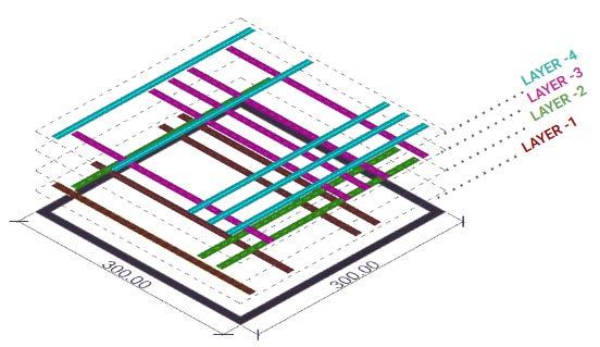
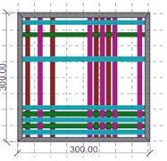
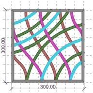
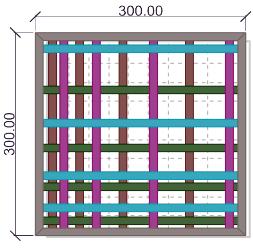
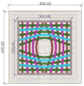
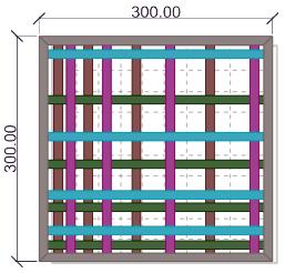
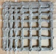
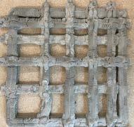
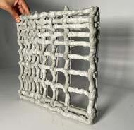
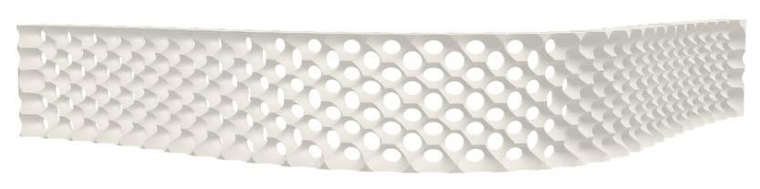
As per the printing technique vertical printing strategy was not working. The system which I was using which is a pressure based extruding is not good for printing vertical as the below lay er collapse while printing above, so here I took a major turn of changing the strategy by print ing horizontal and wider and create a panelling system. The panel will be design as per the environmental analysis ( solar and radition anal ysis). The new techniques combines 2 strategy which is pritning in weaving concept and mak ing module or panel system. Later on the pan el will be combines to form a facade system.
PRINTING PANEL Weaving Concept MODULE PRINTING COMBINATION
10 11

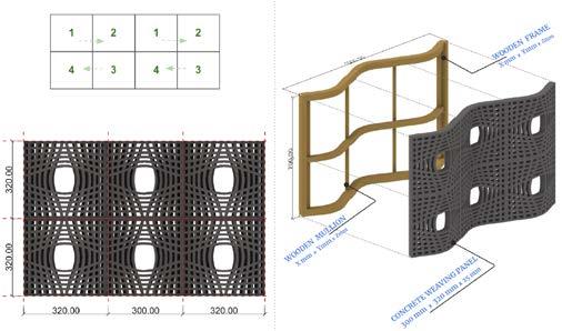
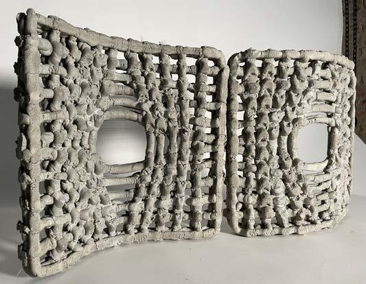
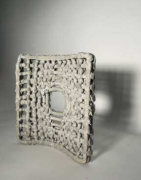
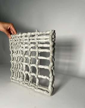
WEAVING PANELS DESIGN CATALOG 4) ROBOTIC FABRICATION - WEAVING PANEL STRATEGY - 1 PANEL STRATEGY - 2 PANEL STRATEGY - 3 ROBOTIC STEUP - pressure base extruder LAYERING PRINTING STRATEGY - Single panel - 10% Visibility - Mesh Pattern - Single Layer Panel - Distance between base and nossel is 80 mm. - Layer Height 12mm - 50-60% Visibility - Mesh Pattern - Single Layer Panel - Distance between base and nossel is 6 mm. - Layer Height 5mm - 70-80% Visibility - Mesh Pattern - Double Layer Panel - Distance between base and nossel is 6 mm. - Layer Height 5mm PLANAR PANEL CATLOG Layer Height - 5 mm Layer Thickness - 10 to 20 mm Water Ratio - 22 % Sand Ratio - 5 % Porosity - 50 30 & 10 % No. of layers - 2 sets of layers With Reinforcement SINGLE LAYER DOUBLE LAYER LAYER INTERSECTION LAYER INTERSECTION PHYSICAL PROTOTYPE PHYSICAL PROTOTYPE Layer Height - 5 mm Layer Thickness - 12 mm Water Ratio - 22 % Sand Ratio - 5 % Porosity - 30 & 10 % No. of layers - 2 sets of layers With Reinforcement NON PLANAR PANEL CATLOG LAYER INTERSECTION SINGLE LAYER LAYER INTERSECTION PHYSICAL PROTOTYPE PHYSICAL PROTOTYPECURVE SINGLE LAYER 12 13
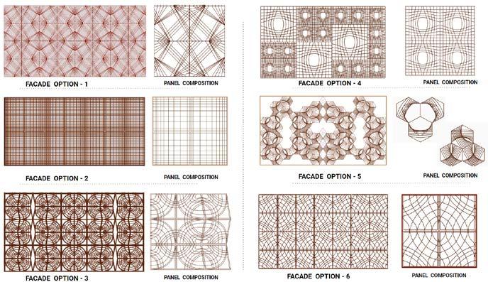

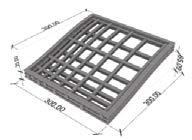
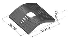
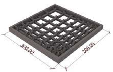
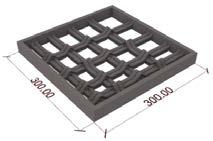

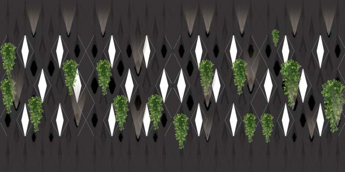
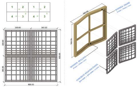
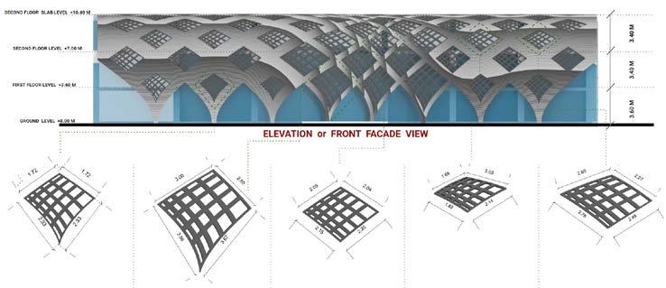
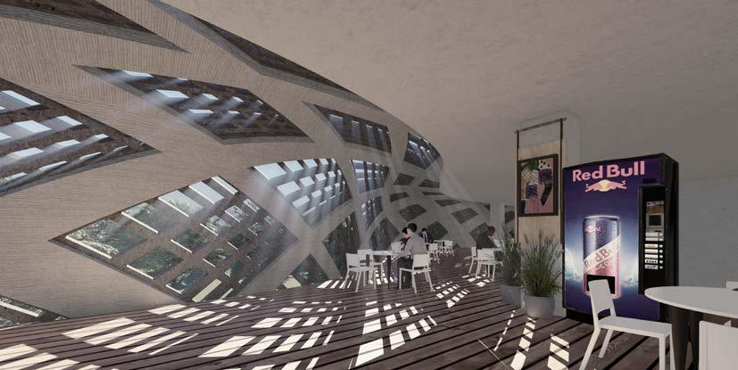
5) WEAVING PANEL COMBINATION PANEL COMPOSITION - 1 PANEL COMPOSITION -2 5) DESIGN APPLICATION CONCEPTUALSKETCHSECTION GRID FORMATION ON SURFACE GRID DEFORMATION ON BASIS OFVALUERADIATION CONCRETE 3D PRINTED PANEL BY WEAVING GRID DEFORMATION ON BASIS OFVALUERADIATION DESIGN WORKFLOW ALL UNITS ARE IN METERS DEATIAL PANEL - 1 DEATIAL PANEL - 2 DEATIAL PANEL -3 DEATIAL PANEL - 4 DEATIAL PANEL - 5 ARCHITECTURAL APPLICATION RENDERPHYSICAL PROTOTYPE COMPOSITION PHYSICAL PROTOTYPE LIGHT SHADOW PLAY PHYSICAL PROTOTYPE LIGHT SHADOW PLAY PHYSICAL PROTOTYPE LIGHT SHADOW PLAY 14 15
DESIGN PROJECTS - AFTER GAUDI 18 - ROHTANG HOTEL , MANALSU .......................................... 24 - PANVEL AIRPORT , FACADE DESIGN 30 - SAVARTRI KIDNEY CARE HOSPITAL .................................. 40 - AGRICULTURAL COLLEGE CAMPUS PROPOSAL ............... 42 Computational project of ¨Alogrithmic Emergence
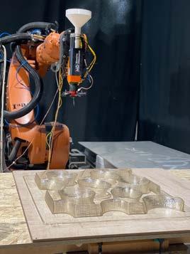
Second process was to understand the process while physically fabricating the hyperboloids. There were 2 process of fabrication.
1. Understand lesser-known but crucially innovative aspects of Gaudí’s design approach appli cable for our time.
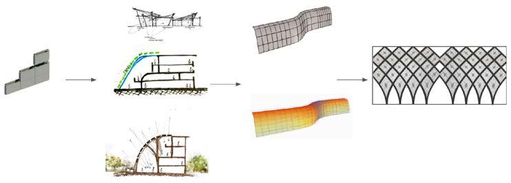
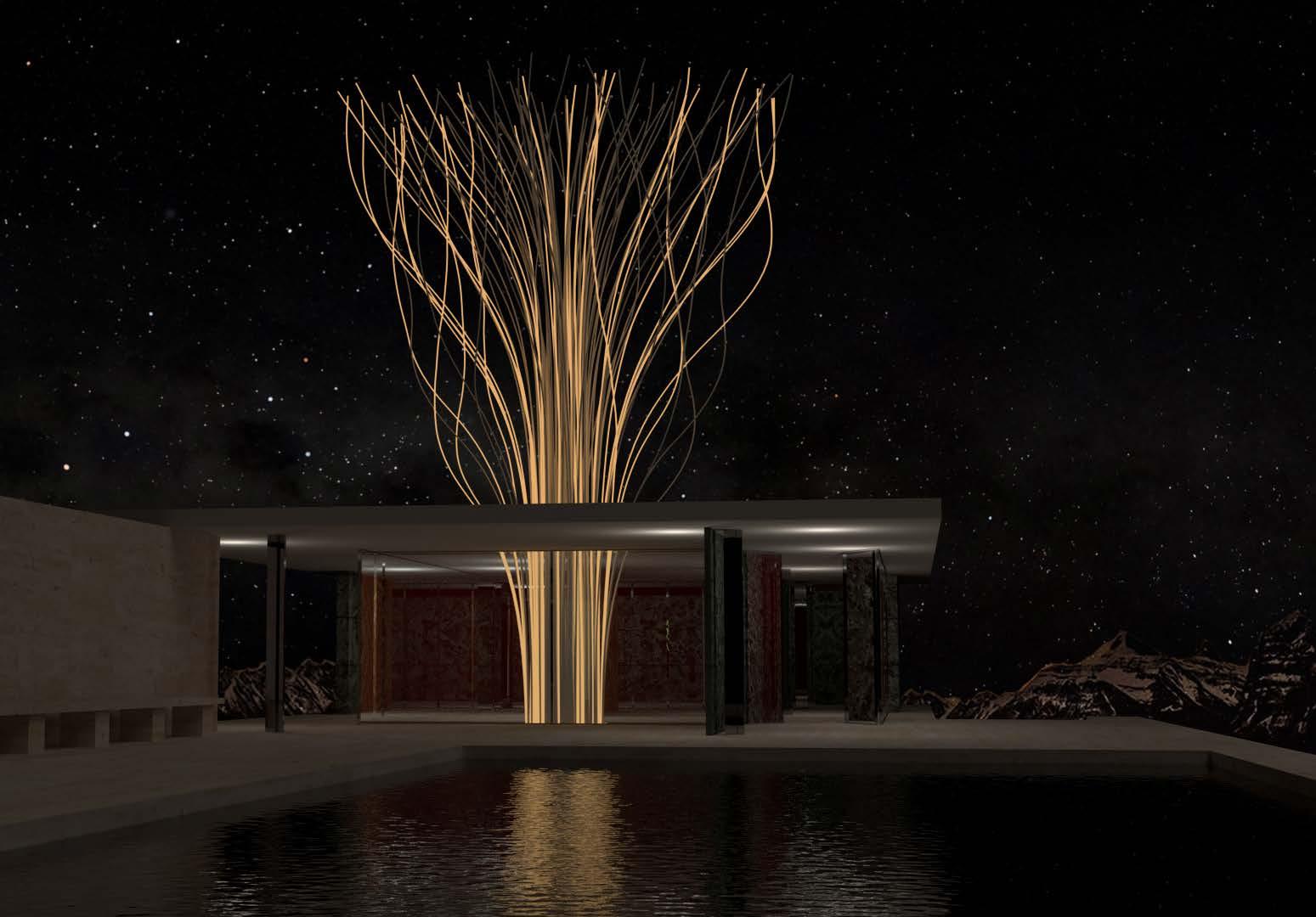
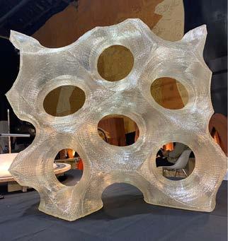
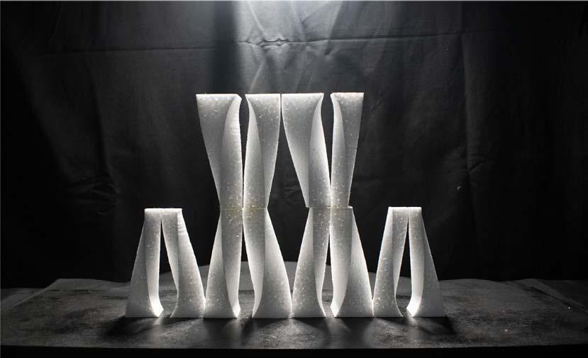
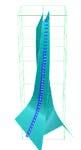
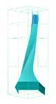
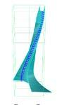
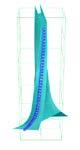
AFTER GAUDI :- FROM CONPUTATIONAL TO COMPOSITION HYPERBOLOIDS FACADE
The main objective for facade design were :-
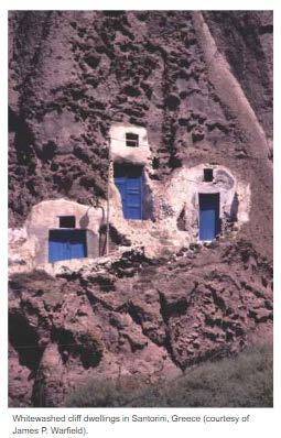
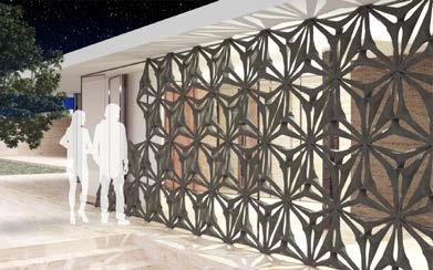
First, with a brief understanding of illuminating interior of Sagrada Familia Basilica, we have to design a facade for a structure in Greece (area specified by the professor) with an additional layer of optimization and adapt to craft the facade parametrically with maximum environmental perfor mance criteria.
MAA02 - DESIGN WORKSHOP
Location :- Institute of Advanced Architecture GROUP PROJECTS (Worked on material fabrication with written and oral presenation. Also worked with computational optimization tool to design facade )
18 19
4. Introduce participants to the subtleties of Gaudí’s parametric design.
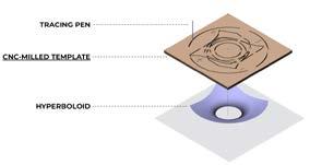
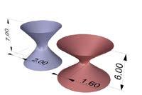
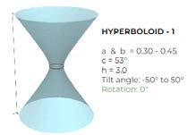
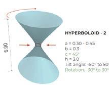
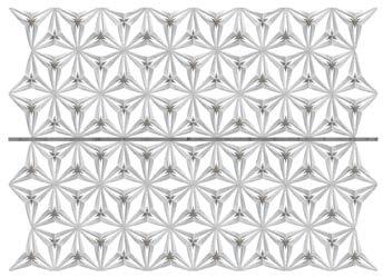
The workshop brief was to design a facade inspired from Gaudi´s parametric design and under stand the richness of his use of Hyperboloids geometries. In the digital workbench, we have to develop a tool for sculpting a building facade while simultaneously adapting physical techniques to experiment with intersection of hyperboliods.
2. Explore the role of the architect to adopt design strategies more familiar to the sculptor.
3. Compare and contrast physical and digital representations of design intentions, especially with regard for planned-for environmental performance.
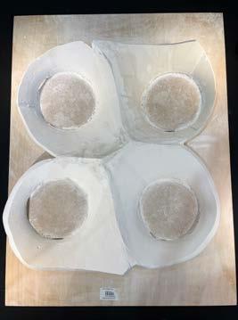
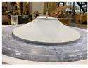
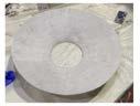
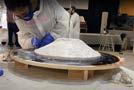
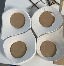
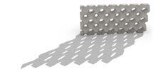
Create a Hyperboloids with the bare hands with the material ¨Plaster of paris¨. Create a Hyperboloids with the robotic printing with PLA plastic
The whole workshop was done under the supervision of Prof. Mark Burry ( Senior Architect to the Sagrada Família Basilica ) and Rodrigo Aguirre ( specialized in algorithmic design and also our professor )
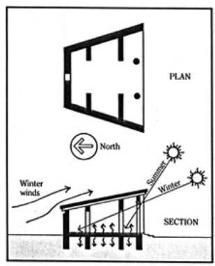
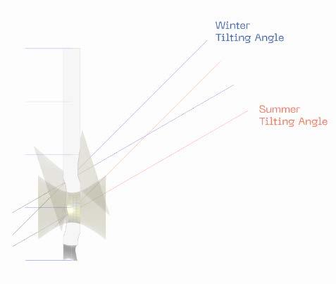
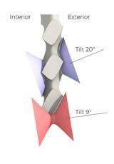
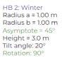
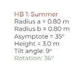
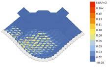
The projects aim is to design a facade system which provides sufficient natural light to the interior, as well as passively heats and cools the rooms depending on the seasonal demands. The site is located in Greece, for this solar and weather condition it is necessary to provide shading for passively cooling the building in summer. In contrast to the winter case, where it’s possible to heat up the interior with the use of solar radiation and direct sunlight.
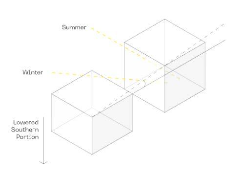
Socrates House is a trapezoid shaped house with the long side facing the sun. The roof over hang on the south blocks the hot summer sun, yet allows the winter sun to penetrate into the home. The roof slopes down in the back to avoid winter winds.
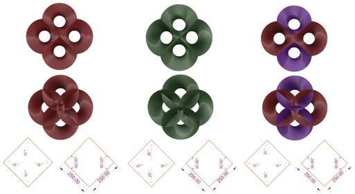
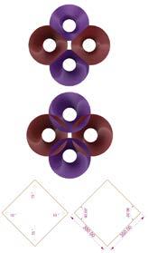
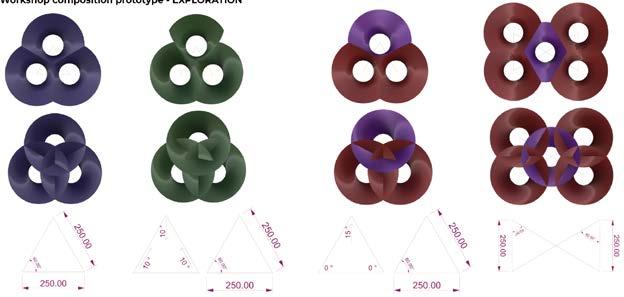
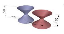
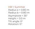
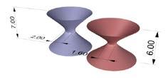
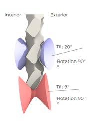
Here are some catalog to explore the variation in hyperboloids by changing their sizes and rota tion to get different output. While exploration we have use the concept of Socrates House.
CATALOG OF HYPERBOLOIDS FOR PLASTER OF PARIS
1 MODULE
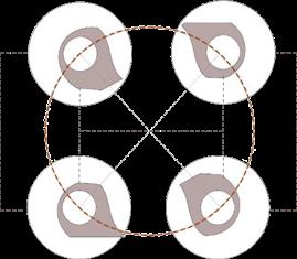
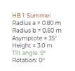
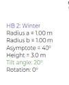
PYSICAL OUTPUT FOR PLASTER OF PARIS - Radius = 25 cm (exterior) - Rotation = 10 degree - Centre to centre distance 30 cm OPTION -9 - - 2 -
MODULE
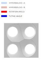
3 MODULE - 4 MODULEACTUAL CUTOUT MODULE FOR COMPOSITION MODULEACTUAL WORKSHOP COMPOSITION HYPERBOLOIDS PROTOTYPE 4. CUTTING TECHNIQUE 5. COMPOSITION OF 4 HYPERBOLOIDS 6. FINAL PROTOTYPE OUTPUT 1. BASE MOULD 2. POUR POP ON THE BASE MOULD TO CREATE THE HYPERBOLOIDS 3. HYPERBOLOIDS OUTPUT Exploded diagram of the selected composition for prototyping 20 21
The Southern side is lowered to allow more sunlight into the house during winter.
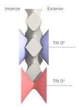
Socrates’ sun-tempered house Strategy for opening on exterior wall Strategy for sculpting hyperboloid on exterior wall
SUN-INFORMED ARCHITECTURE OF
- Radius = 25 cm (exterior) - Rotation = 10 degree - Centre to centre distance 25 cm OPTION - 1 - Radius = 25 cm (exterior) - Rotation = 20 degree - Centre to centre distance 25 cm OPTION -2 - Radius = 25 cm (exterior) - Rotation = 10 & 20 degree - Centre to centre distance 25 cm OPTION -3 - Radius = 25 cm (exterior) - Rotation = 10 & 20 degree - Centre to centre distance 35 cm OPTION -4 - Radius = 25 cm (exterior) - Rotation = No rotation - Centre to centre distance 25 cm OPTION -5 - Radius = 25 cm (exterior) - Rotation = 10 degree - Centre to centre distance 25 cm OPTION - 6 - Radius = 25 cm (exterior) - Rotation = 15 degree - Centre to centre distance 25 cm OPTION - 7 - Radius = 25 cm (exterior) - Rotation = No rotation - Centre to centre distance 25 cm OPTION -8
CONCEPT DEVELOPMENT
CLASSICAL GREECE
MODULE


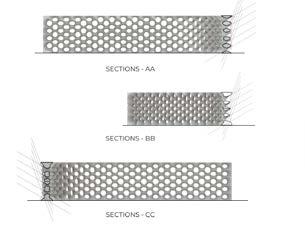
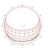
CATALOG OF HYPERBOLOIDS WITH COMPUTATIONAL ALGORITHMS OPTION - 1 OPTION - 2 HYPERBOLOIDS DETAILS SECTION SS SCULPTING HYPERBOLOIDS FROM WALL SHADOW ANALYSIS OF WALL SECTION SS SCULPTING HYPERBOLOIDS FROM WALL SHADOW ANALYSIS OF WALL SCULPTING HYPERBOLOIDS FROM WALL SHADOW ANALYSIS OF WALL SECTION SS OPTION - 3 HYPERBOLOIDS DETAILS HYPERBOLOIDS DETAILS FINAL DESIGN CONCEPTUALPLANSTRUCTURE SECTIONAL ELEVATION KEY PLAN FRONT ELEVATION SUNLIGHT & SHADOW ANALYSIS RADIATION ANALYSIS HYPERBOLOIDS DETAILS FINAL OUTPUT 22 23


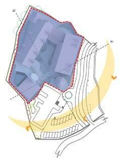
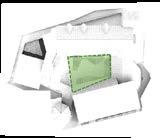
Open spaces act as interdiciplnary interactive spaces 1 2 4 3 DESIGN & SPACE DIVISION CONCEPT EXISITNG SITE LAYOUT WITH BUILDING PROPOSAL 24 25
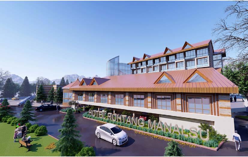
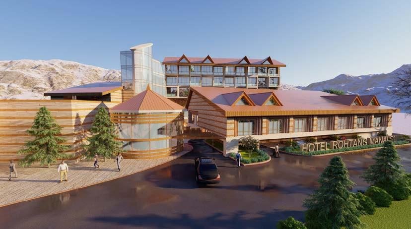
Location :- MANALI , HIMACHAL PRADESH, INDIA. Project Role :- Jr. Architect (worked for design developemnt drawings with written and oral presenation. Also collaborated with 3d rendering )
The project brief was to proposal a design and allied services, which should be developed by incorporating the parameters stated in the Expression of Interest towards the construction of an additional block for a exsisting 4 star hotel within the premises of Rohtang Manalsu Hotel property. As per the requirements we have to provide some business meeting interaction spaces , some extra delux rooms and extension of recreational spaces with proper services
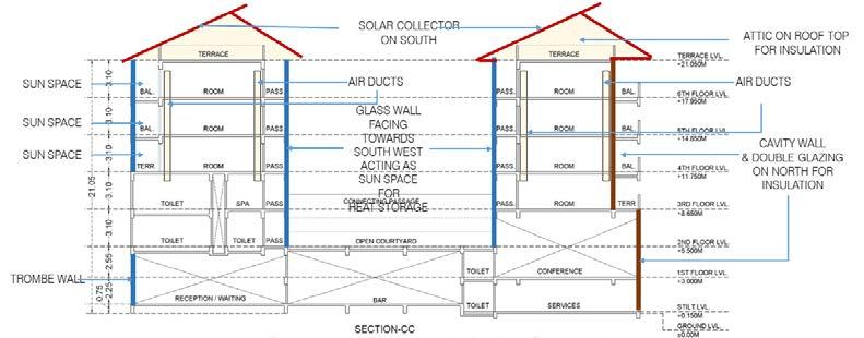
ROHTANG HOTEL , MANALSU
The design concept was TAPASYA, which derived from a strong expression of gratitude and respect to Goddess Hadimba Devi. Here we were trying to represent Tapasya as a purification process which create a sence of warmth and spiritual balance towards Moksha Traingle combining all the chakras within body, which is considered for evolution of forms of the building Single mass of buidling is divided into 2 different masses by corridoors and various interactive spaces. Voids are created in the forms of terraces and courtyard to break the continuity of spaces and merge open and enclosed spaces.
DESIGN DEVELOPMENT OF 5 - STAR HOTEL


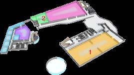
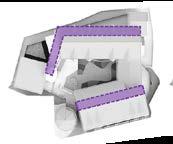
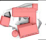
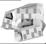
The structure is oriented in such a manner that the major courtyard faces towards the south west direction. In which case more of heat within the structure.
Occupied spaces with daytime activities are zoned towards the South-East to Sounth-West direction to enhance the heat gain and less use of electrical devices to comfort the space.
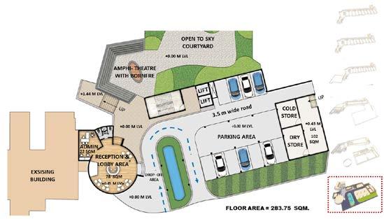
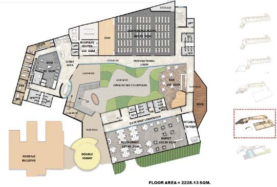
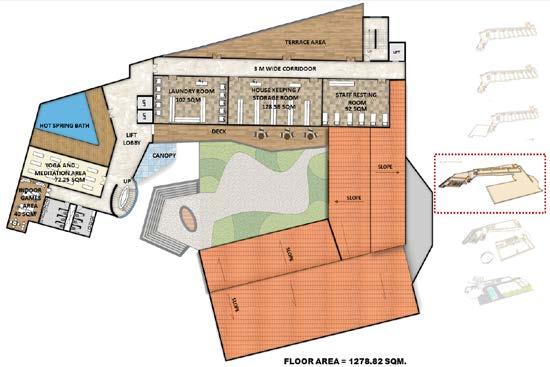
SPACE PLANNING SITE PLAN SPACE PLANNING RELATED TO CONCEPT & CLIMATE GROUND1.SECONDFIRSTFLOORFLOORFIRSTFLOORFLOORCOURTYARD2.RECEPTION&ENTRANCELOBBY1. 1.1.2.RESTAURANTBUSINESSCENTERGYMAREA2.SPA&AYURVEDICMESSAGEROOM3.CONFERENCEROOMHOTSPRINGBATH2.MEDITATION&YOGAROOM3.UTILITYROOM4.INDOORGAMEROOMS Inner courtyard helps in trapping solar heat INNERPASSAGESCOURTYARD Inward passage acts as sun spaces South facing facade and roof are of darker shades to absorb heat and allow passive heating in side theFACADEstructure&ROOF Solar panels are southward inclined on the roof for power generation SOLAR PANELS ROOF DETAIL FLOOR PLANS with repect to areas requirements GROUND FLOOR FIRST SECONDFLOORFLOOR 26 27
ORIENTATION


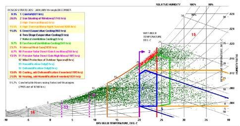
Psychrometric chart explains the ef fective strategy for passivecomfort is Internal Heat Gain & Solar Shading Around 57% of total comfort hours can be achevied by Sun Shading and In ternal Heat Gain and rest 34% will be using electrical appliances for dry bulb temperarture.
28 29
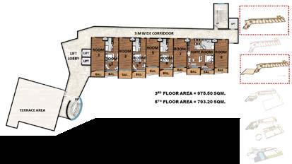
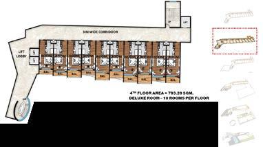
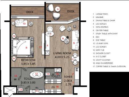
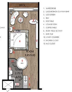
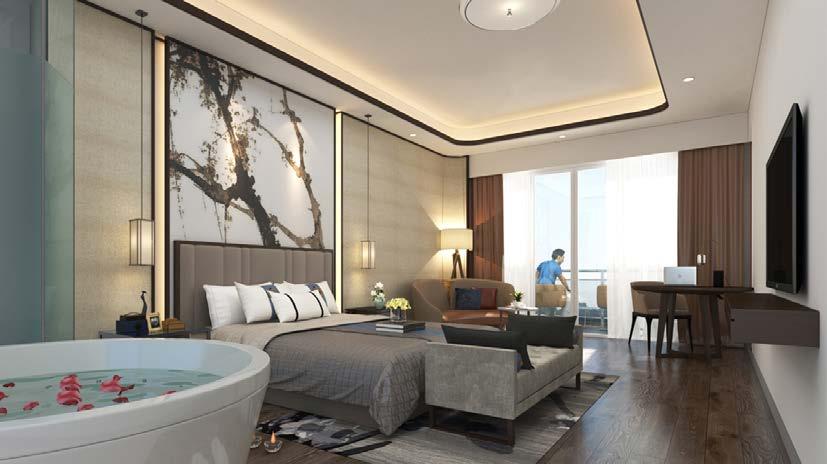
DETAIL FLOOR PLANS with repect to areas requirements THIRD & FIFTH FLOOR FOURTH FLOOR STANDARD ROOM RENDER SUITE ROOM STANDARD ROOM BUILDING SECTION - passive heating strategies PROPOSED STRUCTURE RENDER
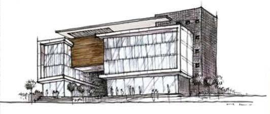
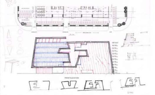
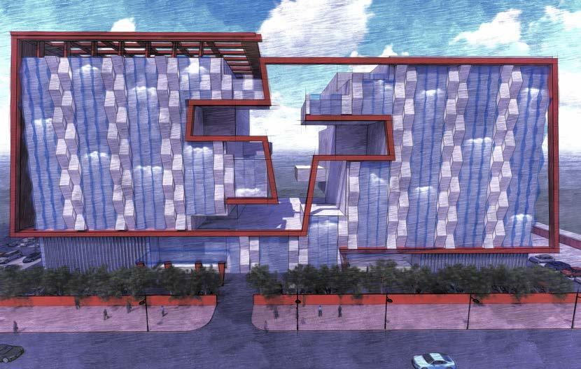
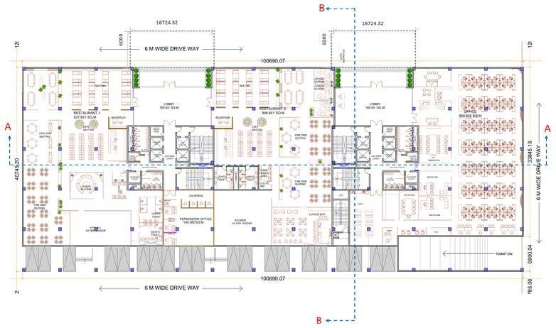
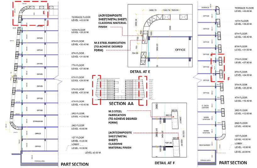
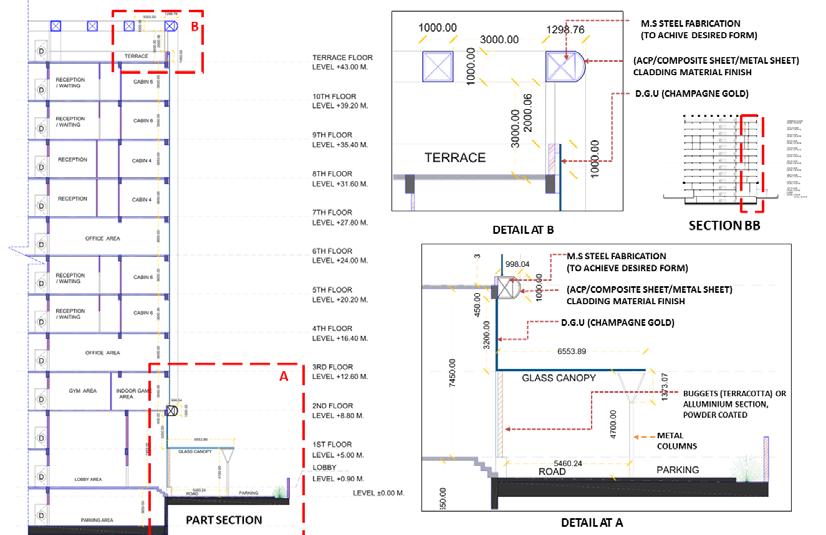
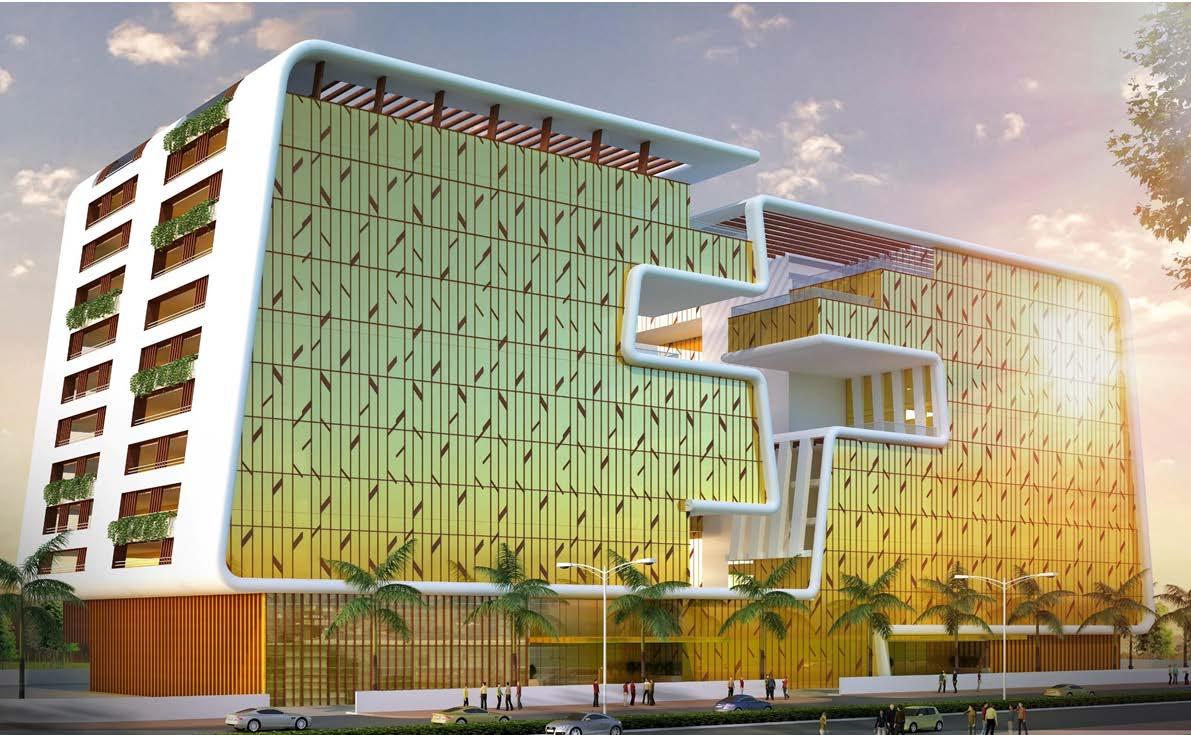
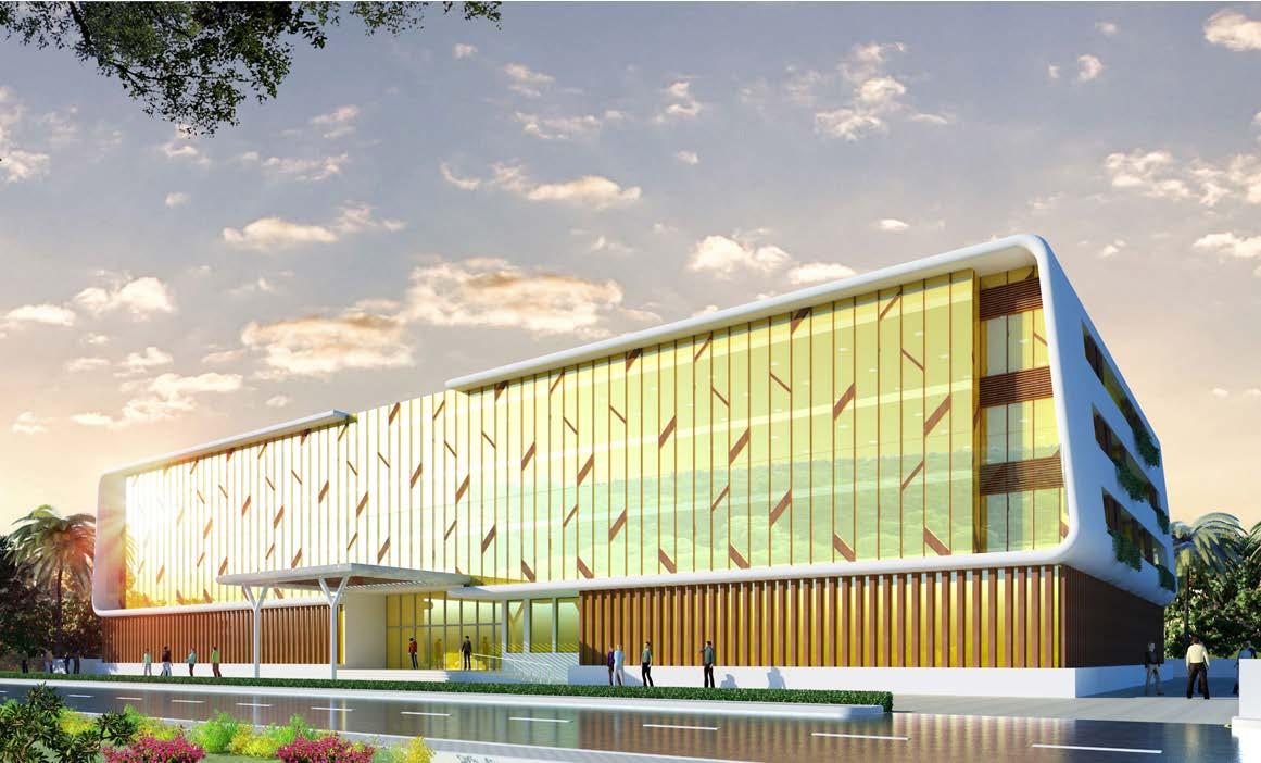
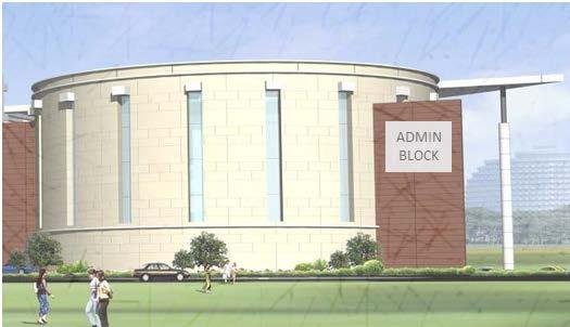
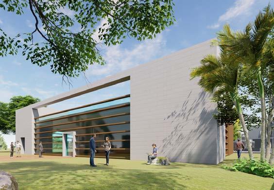
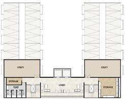
ADMINISTRATION & AIR SUPPORT BUILDINGS - FACADE DEVELOPMENT
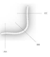
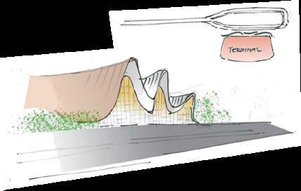
The utility building though smaller in size are pro posed to form a part of the terminal building and appear of same family.
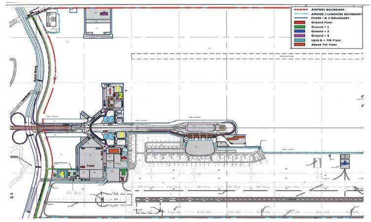
PANVEL AIRPORT
Location :- NAVI MUMBAI , MAHARASHTRA , INDIA. Project Role :- Jr. Architect (worked for facade design developemnt drawings with written and oral presenation. Also col laborated with 3d rendering )
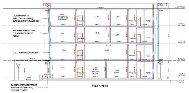
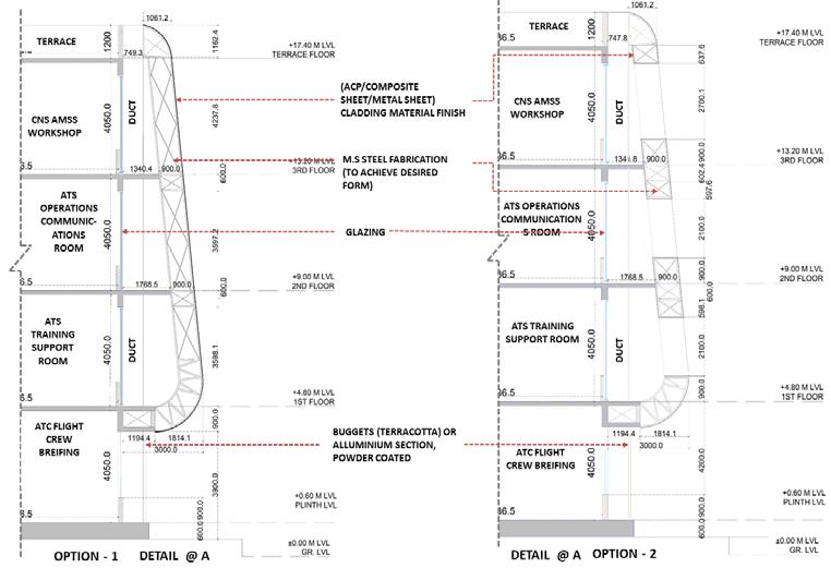
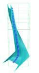
The frames around the building is to form facade element and curvilinear charaterstic adopted at the junction of change in inclination.
The project brief is to design facade for the sup porting building for the airport. Here we have to create an elevation language sinilar to the termi nal building ( as showen in the sketch beside)
4 - STRUCTURES FOR FACADE DEVELOPMENT 4. INSTRUMENTATIONMETEOLOGICALDEPARTMENT3. ADMINISTRATIONDEPARTMENT1. AIR DEPARTMENTCONTROLTRAFFIC 2. ORGANISATIONHEALTHAIRPORT CONCEPTUAL FACADE OPTION - 1 CONCEPTUAL FACADE OPTIONSITE2 PLAN TERMINAL BUILDING SKETCH 30 31

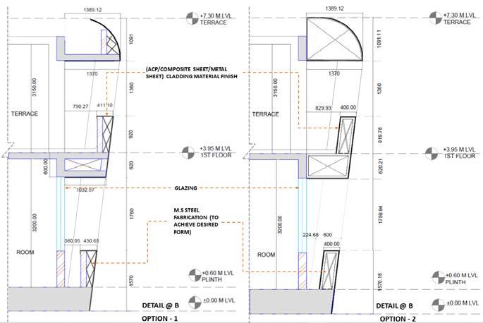
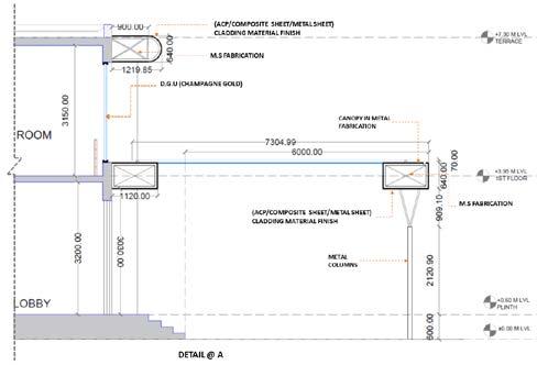
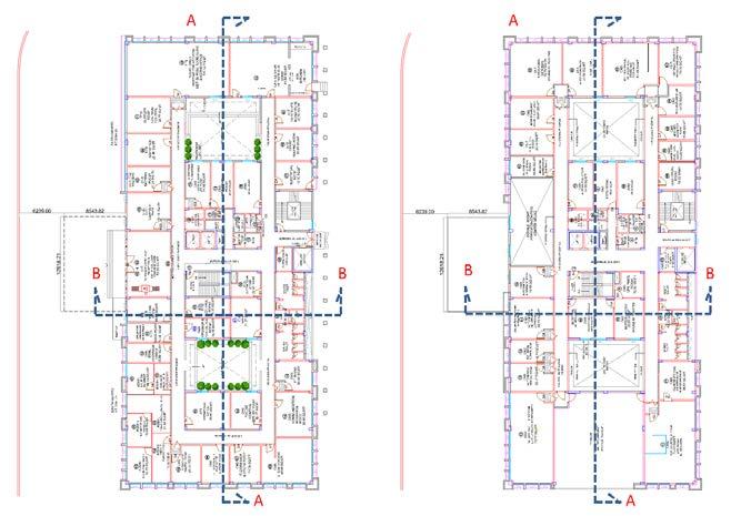
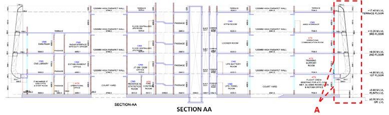
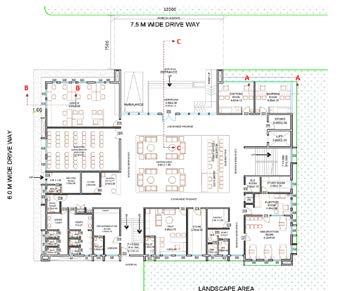
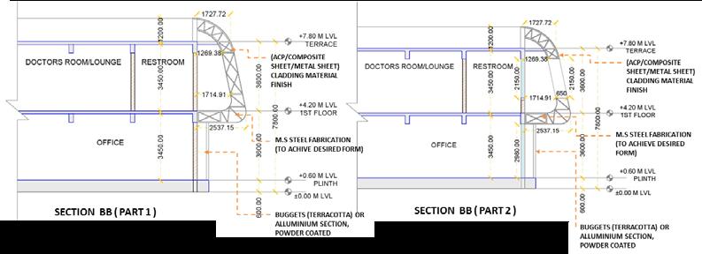
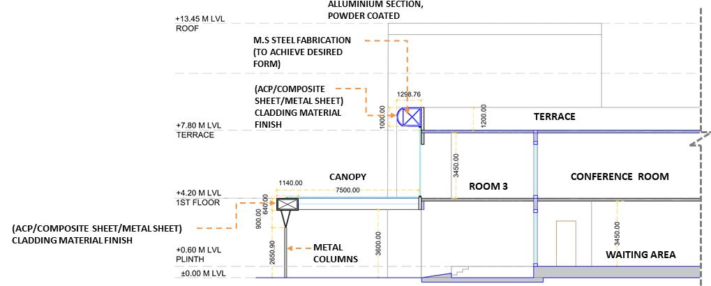
AIR TRAFFIC CONTROL DEPARTMENTFLOOR PLANS SECTIONS WORKING DRAWING FOR FACADE CONSTRUCTION DETAIL @ B WORKING DRAWING FOR FACADE CONSTRUCTION DETAIL @ A CONCEPTUAL RENDER 32 33
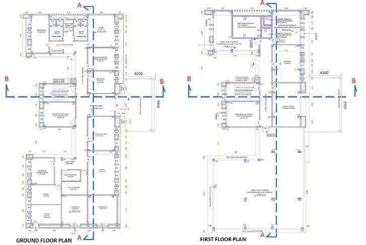
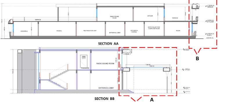

ADMINISTRATION DEPARTMENTFLOOR PLAN WORKING DRAWING FOR FACADE CONSTRUCTION SECTION AA 34 35 WORKING DRAWING FOR FACADE CONSTRUCTION SECTION BB CONCEPTUAL RENDER
DEPARTMENTFLOORPLANS
36 37 WORKING DRAWING FOR FACADE CONSTRUCTION DETAIL @ A CONCEPTUAL RENDER
INSTRUMENTATION METEOROLOGICAL
38 39 AIRPORT HEALTH ORGANISATION WORKING DRAWING FOR FACADE CONSTRUCTION SECTION AAFLOOR PLAN WORKING DRAWING FOR FACADE CONSTRUCTION SECTION BB WORKING DRAWING FOR FACADE CONSTRUCTION SECTION CC

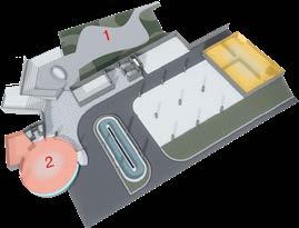
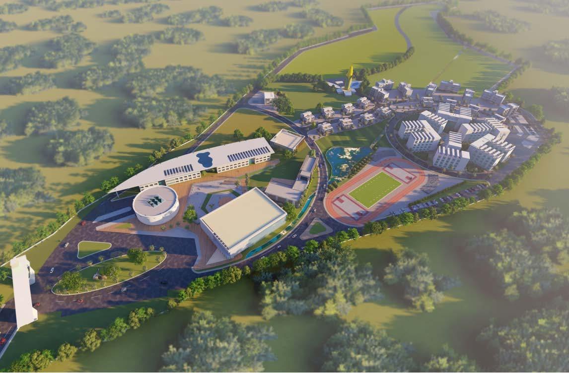
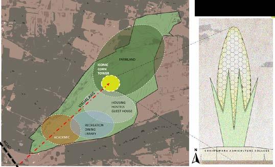
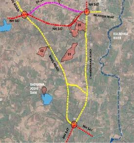
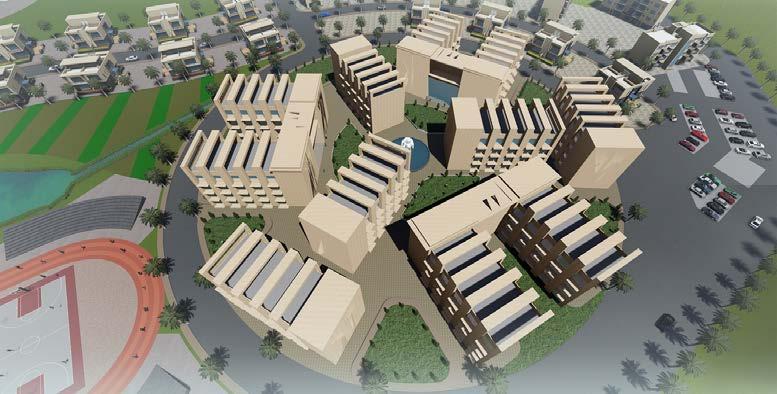
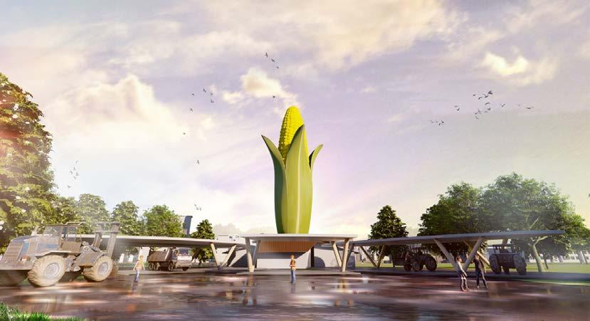
The project majorly concerned with the proposal of conceptual design for Agricultural College Campus. The important factor is to use only 40% of the land for the campus development and the remaining will be use for farming mainly and 2 phase develpemnt. We had 3 site for the proposal which was divided for a agricultral college campus & horticulture college campus.
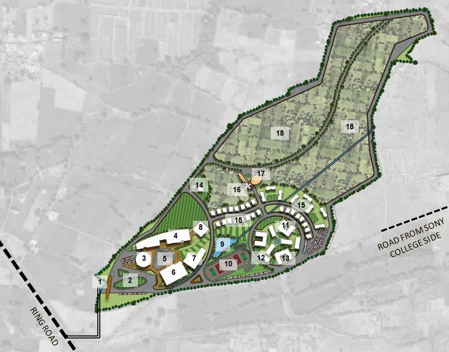
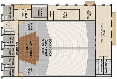
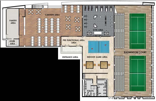
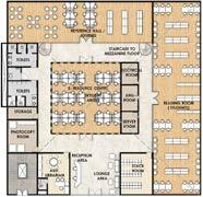
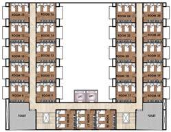
1 - MAIN ENTRANCE GATE. 2 - ENTRANCEPLAZA 3 - AMINISTRATIVEBLOCK 4 - DEPARTMENT / FACULTY BUILDING 5 - AMPHI THEATRE 6 - RECREATIONAL BLOCK 7 - AUDITORIUM 8 - LIBRARY 9 - CENTRAL WATER FEATURE 10 - RUNNING TRACK & COURTS 11 - HOSTEL BLOCKS 12 - INTERNATIONAL HOSTEL 13 - GUEST HOUSE 14 - DEAN BUNGALOW 15 - STAFF HOUSING 16 - ICONIC STUCTURE 17 - FARM / ORCHARD OFFICE 18 - FARMING LAND SITE PLANS VEHICULAR PEDESTRIANCONNECTIVITYCONNECTIVITYVEHICLEPARKING CONCEPTUAL PLANNING with PHASE DIVISION and CONCEPTUAL SKETCH for ORCHID OFFICE & STORAGE 42 43
DESIGN PROPOSAL FOR COLLEGE CAMPUS Location :- CHHINDWARA MADHYA PRADESH , INDIA. Project Role :- Jr. Architect (worked for facade design developemnt drawings with written and oral presenation. Also collaborated with 3d rendering ) AGRICULTURAL COLLEGE CAMPUS

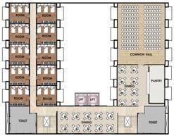
DETAIL INTERIOR FLOOR PLANS FOR SOME ADMINISTARTIONSTRUCTURESBUILDING(1999.20 sqm) GROUND FLOOR PLAN FIRST FLOOR PLAN CONCEPTUAL RENDER AUDITORIUM BUILDING ( 2034.63 sqm) CONCEPTUAL RENDERGROUND FLOOR PLAN CONCEPTUAL RENDER GROUND FLOOR PLANRECREATIONAL BUILDING (1139 sqm)LIBRARAY & DISPENSARY BUILDING ( 900 sqm) GROUND FLOOR PLAN FIRST FLOOR PLAN HOSTEL BUILDING (1949.70 sqm) GROUND FLOOR PLAN FIRST FLOOR PLAN SECOND FLOOR PLAN 44


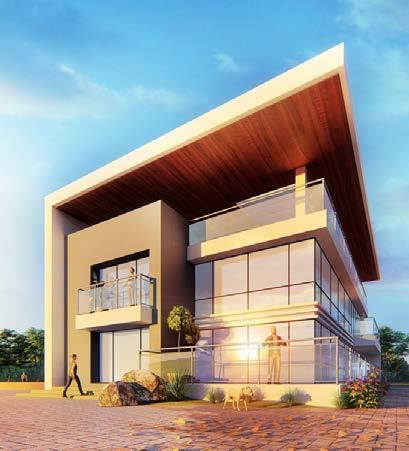
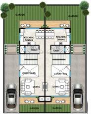
ASSOCIATE PROFFSOR HOUSES (115 sqm) GROUND FLOOR PLAN CONCEPTUAL RENDER DEAN´S BUNGLOW (165 sqm) GROUND FLOOR PLAN FIRST FLOOR & TERRACE FLOOR PLAN CONCEPTUAL RENDER ASSI. PROFFSOR & TEACHERS HOUSES (3391.80 sqm) GROUND FLOOR PLAN FIRST FLOOR PLAN CONCEPTUAL RENDER The large scale shading and rain cover with integrated harvesting, efficient lighting snd solar power generation Keeping sustainability and global asthetic appeal into consideration, we propose and alternative design Aimelement.isto enhance the green quotient and sustainabil ity of the infrastructure proposed. Low maintance and high durability of the proposed roofing solution contributes in overall feasibility SOLAR PANEL APPLICATION SOLAR PANEL TOWERS Flexible solar module har nesses clean energy and power upto 1080. Smart energy storage algo rithm manages and distrib utes power over days. Energy efficient diffused light system provides a unique glow of light Physical filter uses high flow rates to reduce TSS and large organic matter in the water SOLAR ENERGY HARVESTING 46 47


ROBOTIC FABRICATION - DM ( CARBON COPIES ) ............................................... 50 - HOTWIRE CUTTING ..................................................... 60 - ROBOTIC TUFTING ...................................................... 64
STRATEGIES FOR REDUCING EMBODIED EMISSIONS
Location :- Institute of Advanced Architecture CARBON COPIES
GROUP PROJECTS (worked on robotic fabrication with written and oral presenation. Also collaborated with material composition and computational optimization)
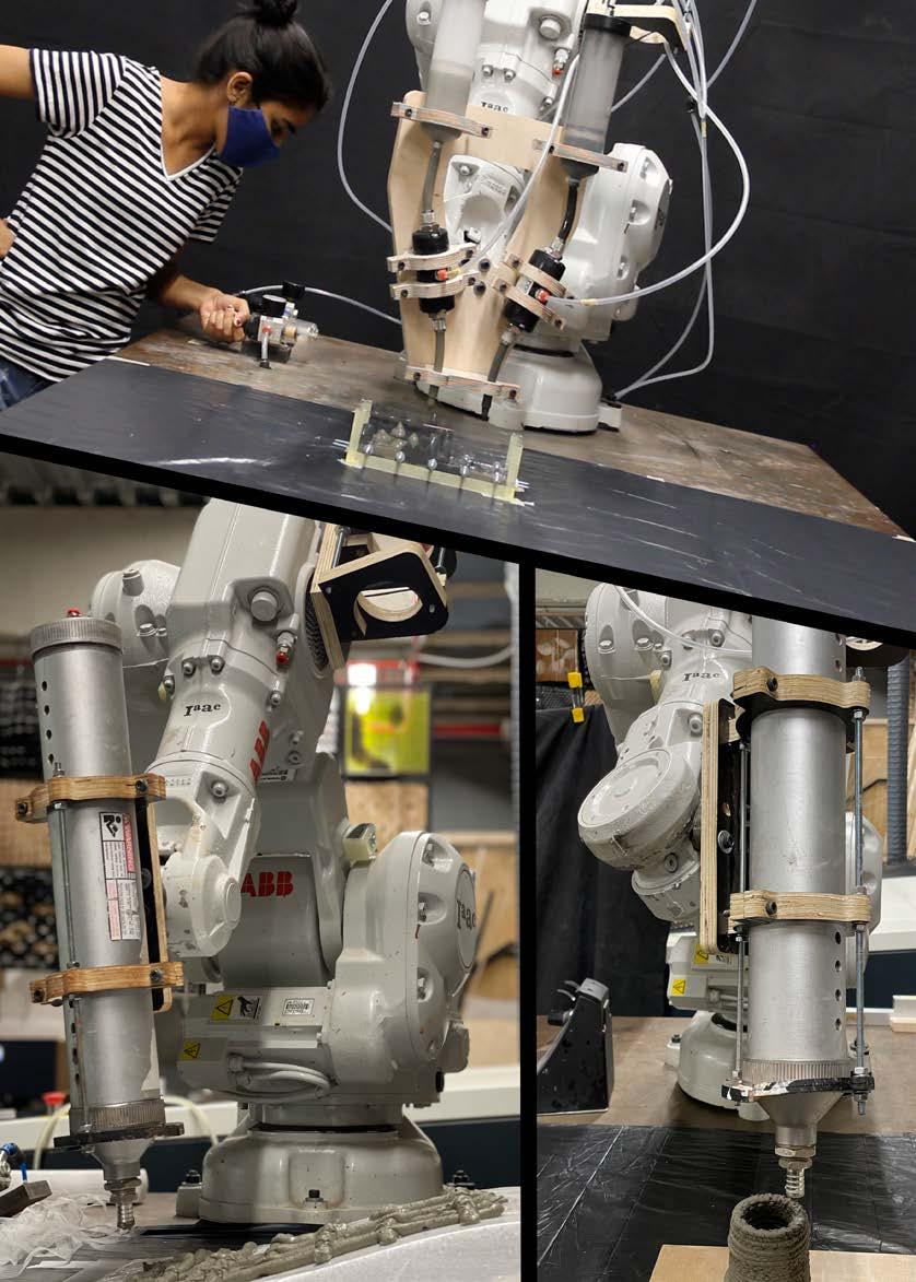
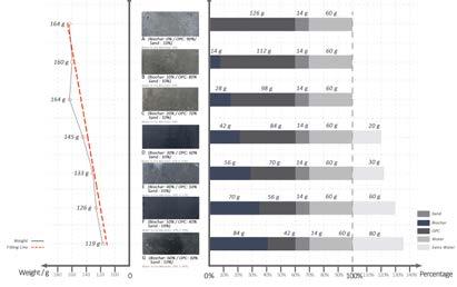
Biochar was selected and studied as partial substitute to concrete, thus facilitating material savings and substantially lowering the amount of embedded carbon in concrete structures. Based on the results of structural optimization of building elements a multi-material casting system operating in conjunction with robotic technologies was developed so concrete can be cast where it is structurally required, while biochar-based mix was used to fill the rest of the formwork.
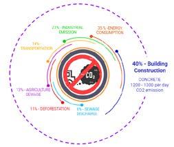
The production of cement, key constituent in concrete, is particularly responsible for the growth of a substantial part of global CO2 emissions. Thus, in the last 20 years traditional concrete manufacturing methods have evolved to improve its ecological and economical sustainability by adapting them to digital fabrication, specifically to additive manufacturing.
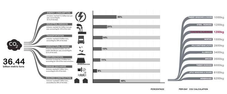
40% of carbon dioxide emission per year is resulted by building construction. 1200kg of carbon dioxide is produced by concrete fabrication per day.
BIO - MATERIAL CASTING OF FUNCTIONALLY GRADED OPTIMIZED STRUCTURAL ELEMNETS MAA02 - DESIGN WORKSHOP
Introduce carbon negative materials to concrete elements to create novel composites.
Decrease cement content during manufacturing
50 51
Carbon copies is a project that focuses on the development of a multi-material concrete casting technique within functionally graded design that provides sustainable and material efficient production method for the construction industry.
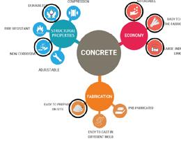
Concrete is the most ubiquitous building material in construction industry. It has withstood the test of time and proved its capabilities by being an exemplary material in terms of general availability and structural performance. Although there are numbers of strong arguments justifying its wide use around the world, it is impossible to overlook the adverse effect that concrete industry has on the environment.
Carbon Emission of Construction Industry

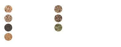
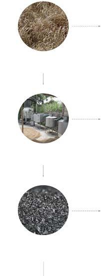
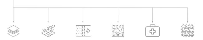
MiscanthusSoftwood Straw Sewage Sludge Rice Husk RAW MATERIALS 1. Air decontamination 2. Humidity regulation 3. Electrosmog 4. Structure substitution 1. Silage agent 2. Feed additive 3. Litter additive 4. Slurry treatment 5. Manure composting 1. Soil additive 2. Soil substrates 3. Preventing pesticides 4. Treating lake water 1. Carbon fertilizer 2. Compost additive 3. Plant protection 4. Compensatory fertilizer Biomaterials Animal Farming Decontamination Soil Conditioner PRODUCEPROCESSBIOCHARPRODUCT Materials Sources: Properties:Process: 1. Detoxification 2. Cataplasm for insect bites 3. Carrier for API 1. Fabric additive 2. Thermal insulation 3. Deodorant Medicines Textiles 1. Raw materials from waste organic matter 2. Drying 3. Grinding into smaller pieces 4. Slow pyrolysis processing 5. Output product 1. 2. 3. 4. 5. Oilseed Rape Straw Wheat Straw Grass Carbon negative Light BiocompatibleNon-toxicweight AbsorbentPorousBiodegradable MANUAL FABRICATION PRODUCTION BIOCHAR LIFECYCLE AND MANUAL PRODUCTION Some basic manual exploration to understand the material composition, weight and bonding strength. The whole process was carried forward after the breif understanding of the production of biochar as a recycleable matter with its carbon emission percentile. Recipe 2 (Cement + Biochar + Water): Recipe 3 (Cement + Biochar + Fiber + Water):Recipe 1 (Cement + Biochar + Sand + Water): 52 53


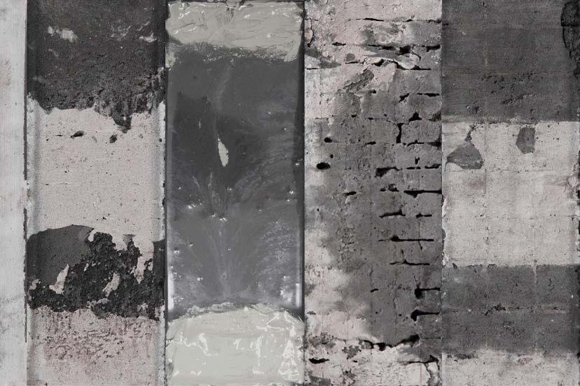
Seamless Casting (Volumetric Approach)
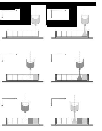
Casting Process: 1. Pouring the mixture into the formwork. 2. Place and shape the strips. 3. Pouring the other type of mixture into the formwork. 1. Grinding into smaller pieces 2. Slow pyrolysis processing 3. Output product 1. Pouring the mixture based on required. 2. Pouring one type of mixtures. 3. Pouring another type of mixtures. 1. Infill one type of mixture frist. 2. Inject another type of mixture. 3. Finish the injection, remove the needle.
Casting
Casting Process: Casting Process: Casting Process: Casting Process: Fabrication Detail: Fabrication Detail: Fabrication Detail: Fabrication Detail: Casting Result: Result Evaluation: Casting Result: Result Evaluation: Casting Result: Result Evaluation: Result: Result
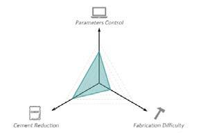
Less More Less More Fabrcation Time EquipmentAccuracyDifficulty Requirement Form Limitation
Seamless Casting (Planar Approach)
Current casting strategy that already wreil used in construction industry.
Advantage:Resulthas high accuracy Fabrication technique is simple
Fabrication Detail: 1. 2. 3. Less More Easy Difficult Low High Geometry: Ruled Surface Additional Required: Yes Materials: Plywood, Membrane Reforcement: Inavailable Geometry: Voxel-based Additional Required: Yes Materials: Reforcement:PlywoodInavailable
Advantage:Adaptable boundary. Suitable for planar (2D) approach. Limitation:Requires additional pre-fabrication step. Optimization result cannot be replicated
Grid Liquid concrete mixture is delivered into a regular shape mold with pre embedded reinforcements.
DIFFERENT
Fabrcation Time EquipmentAccuracyDifficulty Requirement Form Limitation Fabrcation Time EquipmentAccuracyDifficulty Requirement Form Limitation Fabrcation Time EquipmentAccuracyDifficulty Requirement Form Limitation Fabrcation Time EquipmentAccuracyDifficulty Requirement Form
Liquid concrete mixture is delivered into a regular shape mold with pre embedded reinforcements.
Evaluation:Voxel
Geometry: No limit Additional Required: No Materials: Reforcement:PlywoodAvailable Geometry: No limit Additional Required: Yes Materials: Reforcement:PlywoodAvailable 1. 2. 3. 1. 2. 3. 1. 2. 3. 1. 2. 3. STYLES OF CASTING STRATEGIES
Strips Liquid concrete mixture is delivered into a regular shape mold with pre embedded reinforcements.
Advantage:Lessgeometry limitation. No boundary maintenance required Limitation:Hardtoprecisely control the mixture. Requried additional equipments.
Here are some casteing strategy to evaluate the 2 material behaviour with each other and their bonding strength.
A technology of construction of buildingswhere walls
1. Place the grid on the first level. 2. Cast the mixture based on the voxel. 3. Move the grid to second level and cast.
Casting Strategy
A technology of construction of buildingswhere walls Injection Liquid concrete mixture is delivered into a regular shape mold with pre embedded reinforcements.
Limitation:TimeconsumeRequireadditional equipment.
A technology of construction of buildingswhere Tamperingwalls
LimitationGeometry: Voxel-based Additional Required: Yes Materials: Plywood, Acrylic Reforcement: Inavailable
Advantage:Fasttechnique with high surface coverage. No boundary maintenance required Limitation:Notsuitable for complex contours. May require additional equipment
Physical Boundary (Temporary Separators)
Casting Result: Result
accurately.Flexible
Advantage:Requried less equipments. Faster construction time. No boundary maintenance required Limitation:Hardtoprecisely control the mixture. Pouring Liquid concrete mixture is delivered into a regular shape mold with pre embedded reinforcements.
Evaluation: Less More Easy Difficult Low High Less More Less More Less More Easy Difficult Low High Less More Less More Less More Easy Difficult Low High Less More Less More Less More Easy Difficult Low High Less More Less More 54 55


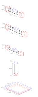
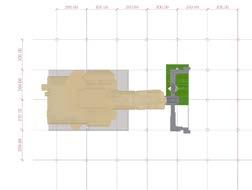
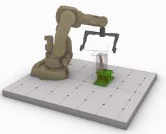
ROBOTIC TOOL PATH SETUP END EFFECTOR DESIGN Extruder Part Vavel Fitting * 2 Cap * Plunger2 * 2 Cartridge * 2 Hose Clamp * 2 Fixed Part 5mm Nut * 4 M5_L40 Screw * 4 Control Part 5mm Nut * 4 M5_L40 Screw * 4 15mm Mounting Fixture 2 15mm Pinch Vavel * 2 Output Part 5mm Nut * 4 M5_L40 Screw * 4 10mm Pipe * 2 15mm Mounting Fixture 2 End EffectorToolPrototypeDesignTargetPathPointsPatternFormworkBaseRobot Robotic System Setup Move to target point Vavel on, wait and pour, vavel off Step 1. Step 2. Move to next target point, shift mixture Vavel on, wait and pour, vavel off Move to next target point, don't shift mixture Vavel on, wait and pour, vavel off Robot Working Principie Step 3. Step 4. Step 5. Step 6. GEOMETRY DESIGN Material deposition in grid mannerStructural Optimization Setup Noise Parameters Filter Ranger: x > 0.25 Filter Operation: Remap to 1 - 4 Function: Sin(x) Frequecy for Function: 5 The workflow explains how a structural object is optimize digitally with millipede and its respective physical output with reinforcement. Here, their was a comparitive analysis between a digital output and physical output in reference to the strength, optimization and weight. Fixed Support Load Applied onStructuralBeam Beam Digital Optimization Output TOP VIEW TOP VIEW FRONT VIEW RIGHT VIEW LEFT VIEW FRONT VIEW RIGHT VIEW LEFT VIEW DIGITAL OUTPUT PHYSICAL OUTPUT 56 57
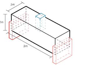


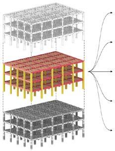
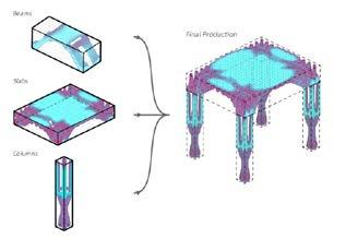
The workflow consists of three parts: digital design part, materials part and the advanced fabrication part. Initially, the model is parametric controlled in Grasshopper. And then with the materials testing result, set up the parameter for optimizing the elements. Lastly, programming the G-code for robotic fabrication.
This is an example shows the digital workflow from designed building to each optimized elements and the corresponding parameters. Extra the force condition and support condition from the Karamba simulation result and apply those data to Millipede to optimize the elements. Main Beam 1 Load:Ground Floor: 3860 kN First Floor: 3774 kN Second Floor: 3650 kN Support Condition: Fix Support Total Amount: 72 Element Volume: 0.81m³ Pure Cement Mass: 2259.9 kg Main Beam 2 Load:Ground Floor: 3860 kN First Floor: 3774 kN Second Floor: 3650 kN Support Condition: Fix Support Total Amount: 75 Element Volume: 1.01m³ Pure Cement Mass: 2999.7 kg Main Beam 3 Load:Ground Floor: 600 kN First Floor: 597 kN Second Floor: 595 kN Support Condition: Fix Support Total Amount: 240 Element Volume: 0.27m³ Pure Cement Mass: 801.9 kg Column Load:Ground Floor: 19806 kN First Floor: 13153 kN Second Floor: 6729 kN Support Condition: Fix Support Total Amount: 90 Element Volume: 1.44m³ Pure Cement Mass: 4276.8 kg Slab Load:Ground Floor: 4804 kN First Floor: 4780 kN Second Floor: 4763 kN Support Condition: Fix Support Total Amount: 60 Element Volume: 7.56m³ Pure Cement Mass: 22453.9 kg Biochar1740.5kgRatio: 28.0% Cement Ratio: 72.0%-170.1kg Biochar1582.9kgRatio: 29.1% Embodied Carbon: -176.8kg Biochar1326.8kgRatio: 41.9% Embodied Carbon: -254.5kg Mass: Biochar2308.1kgRatio: 26.7% Embodied Carbon: -210.0 kg Mass: Cement1982.0kgRatio: 60.0% Embodied Carbon: -300.0 kg Biochar1586.0kgRatio: 56.0% Embodied Carbon: -420.0 Biochar2056.1kgRatio: 37.0% Cement Ratio: -277.5 kg Biochar1858.5Ratio: 45.0% Embodied Carbon: -337.5kg 1512.7 kg Biochar Ratio: 59.0% Embodied Carbon: -442.5 1967.0 kg Biochar Ratio: 40.0% Embodied Carbon: -277.5kg Mass: Biochar1710.3Ratio: 51.0% Embodied Carbon: -382.5 kg Mass: 1438.6 kg Biochar Ratio: 62.0% Embodied Carbon: -465.0 Biochar18860.5kgRatio: 16.0% Cement Ratio: 84.0%-120 kg 10777.4 kg Biochar Ratio: 52.0% Embodied Carbon: -390.0 kg 7858.5 kg Biochar Ratio: 65.0%487.5 Ground Floor
DESIGN WORKFLOW
SHOWCASE
Axonometric View Axonometric View Axonometric View Front View Top View Top View Side View Optimization Result ElementsOutlookTypes Optimization Model Set-upBuilding System Element Catalog First Floor Second Floor Ground Floor First Floor Second Floor Ground Floor First Floor Second Floor Ground Floor First Floor Second Floor Ground Floor First Floor Second Floor Individual member optimization with high performance structural elements ( prefabricated) leading to the final assembly of the structure skeleton on site 58 59


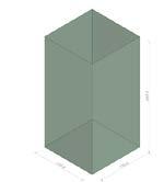
ELEVATIONPLANISOMETRICEPSBLOCK
The toolpath should avoid cutting the model
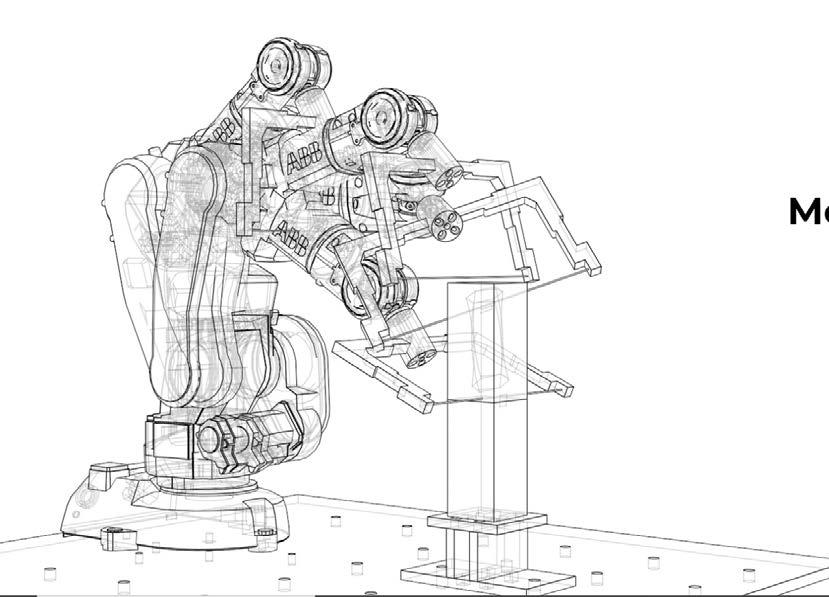
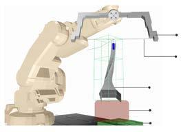
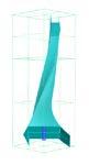
ROBOTIC HOT - WIRE CUTTING - DESIGN WORKSHOP
Location :- Institute of Advanced Architecture
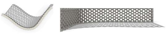
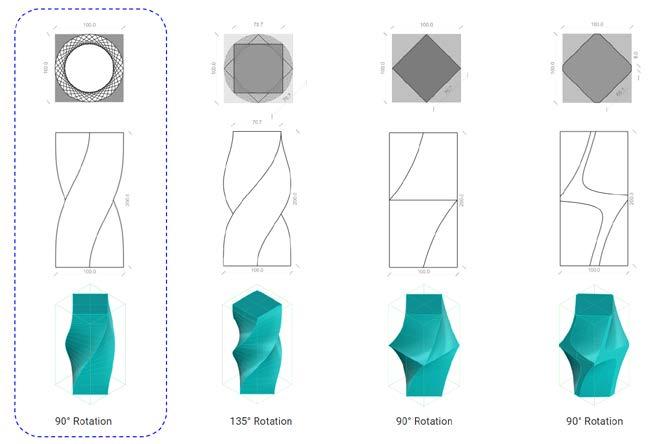
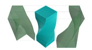
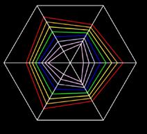
The project objective is to design an aggregating piece using the concept of ruled surfaces and create an effective facade system for barcelona pavilion to enhance the radiation performance of the building as well as enhance the dramatic play of light in and out of the building.
For modeling the blocks certain constraints were taken into consideration such as avoid the singularity and make comfortable movements for the robot Make sure that the tool doesn’t touch the robot.
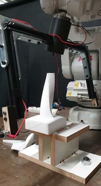
Robotic stereotomy is a group project developed by me and Lekha Gajbhiye. This project aims to understand stereotomy of blocks using a robotic arm. The blocks used are EPS foam blocks and are cut using a hot chromium wire which is guided by the robotic arm.
By modeling the block in rhino and grasshopper the toolpath is generated by using planes as tar gets for the robot which follows them according to their orientation and order.
ROBOTIC STEREOTOMY GROUP PROJECTS ( Lekha Gajbhiye & Aniket Sonawane )
MAA02
OPTIMIZATION BLOCK ROBOTIC DIGITAL OUTPUT TWIST EXPLORATION CATALOGUE 60 61
(worked on computational object developemnt , robotic fabrication with written and oral presenation)
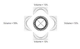
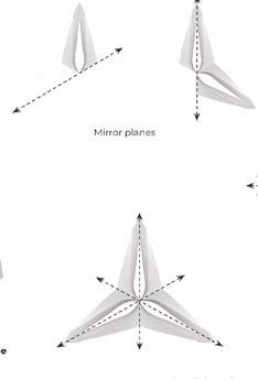
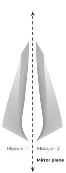
PLAN ELEVATION ISOMETRIC DESIGN OPTION - 1 DESIGN OPTION - 2 MODULE DEVELOPMENT MODULE AGGREGATION BY MIRROR MODULE AGGREGATION IN HEXAGON MIRRORPRINCIPLEPLANES AGGREGATION OF HEXAGON MODULE CUTTING PLANE FACE - 1 CUTTING PLANE FACE - 2 CUTTING PLANE FACE - 3 CUTTING PLANE FACE - 4 CUTTING PLANE FACE - 5 CUTTING PLANE FACE - 6 ROBOTIC MODULE PLACEMENT EPSWOODENHOTWIREBASEBLOCKOPTIMIZEDEPS BLOCK END EFFECTOR FINAL OUTPUT OF EPS BLOCK ROBOTIC STEUP DIGITAL OUTPUT Partition wall 62 63


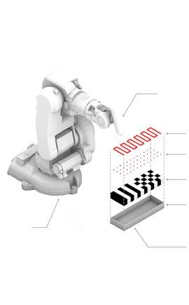
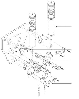
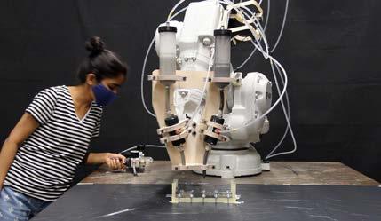
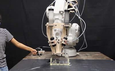
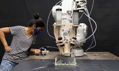
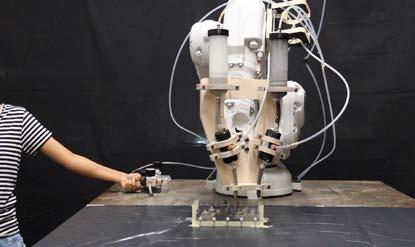
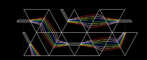
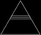
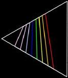
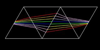
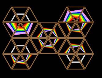
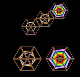
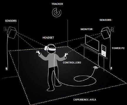
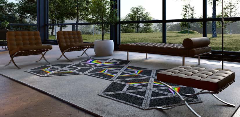
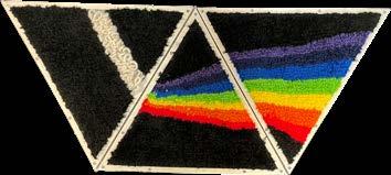
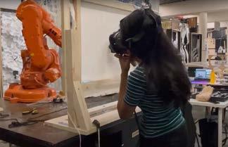
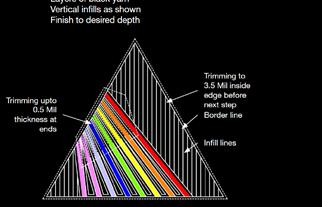
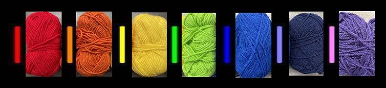
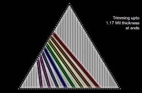
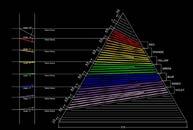
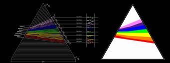
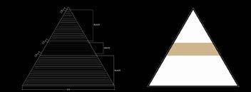
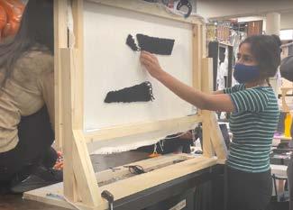
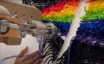
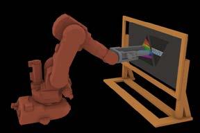
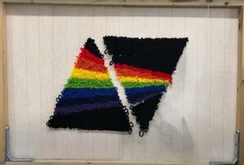
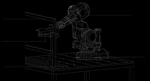
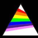
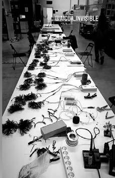
Time is a group project developed to explore the art of tufting by using a robotic arm. The goal is to design a rug with a tufting gun (tool) mounted on the head of the robot which then follows the generated tool path to tuff on a fixed piece of cloth. The design concept is an abstraction of a ray of white light splitting into VIBGYOR spectrum after traveling through a glass prism. The objective was to create a rug with an accurate infill pattern to get a seamless output with the robotic tool path and further the output was trimmed to give a finishing touch. Further explorations were done to combine gesture control of the human hand to create a pattern, which was recorded with an AR system and transferred to the scripts to create targets for the robot to follow.
MODULE - 1 MODULE - 2 MODULE - 3 MODULE AGGREGATION - 1 MODULE AGGREGATION - 2 MODULE AGGREGATION - 3 MODULE AGGREGATION - 4 MODULE AGGREGATION - 5 64 65
Advances in Human-Machine Interfaces(HMI) allow for a seamless collaboration be tween users and devices. MAA02 - DESIGN WORKSHOP Location :- Institute of Advanced Architecture ROBOTIC TUFTING GROUP PROJECTS (worked on computational object developemnt , robotic fabrication with written and oral presenation)
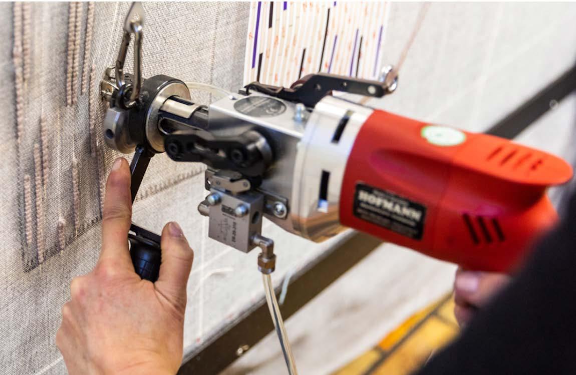

ROBOTIC SETUP FOR FABRICATION FINAL OUTPUT FABRICATION PROCESS VR INTERACTION FABRICATION PROCESS ROBOTIC TUFFTING STRATEGIES FABRICATION SETUP VR INTERACTION SETUP WITH ROBOTIC ARM Curves for Robot Design Output Curves for Robot Design Output Curves for Robot Design Output Design Consideration for Fabrication Design Consideration for Fabrication RoboticRoboticArm Table Tufting Extruder Tool CanvasTuftingSupportCanvas 66
OTHER PROJECTS - LLUM ............................................... 70 - ROBOTIC CLAY PRINTING .................. 74 - PYTHON ( GREEN NOISE) .................. 76
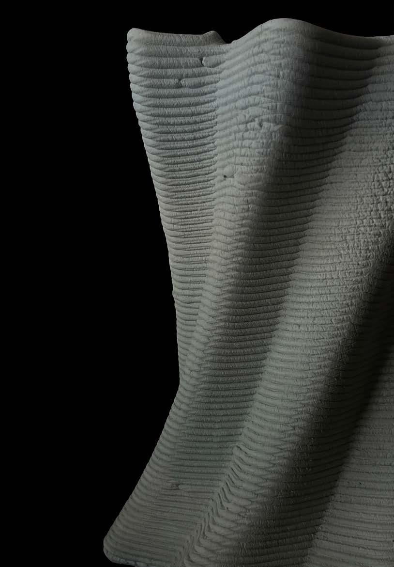
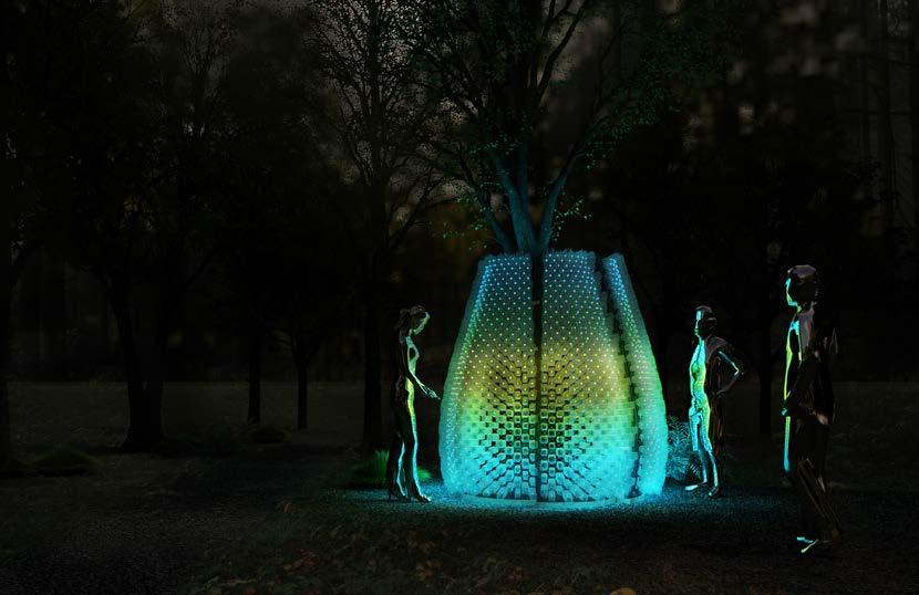
WATER DROPLET PETAL DESIGN WORK FLOW 70 71
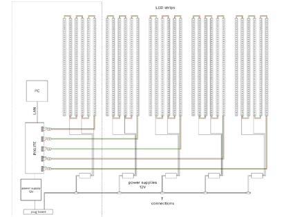
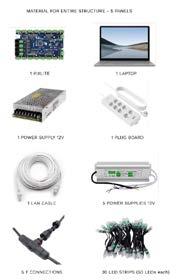
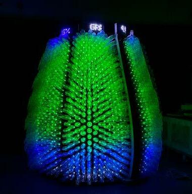
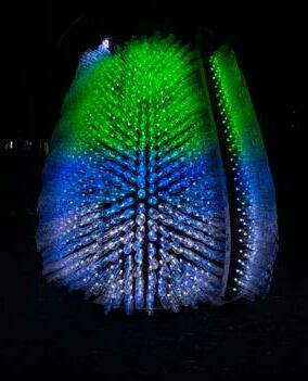
MAA02 - DESIGN WORKSHOP Location :- Institute of Advanced Architecture LLUM PAVILION GROUP PROJECTS (worked on object developemnt , fabrication with technology connection)
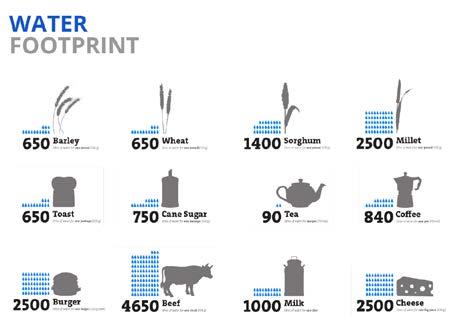
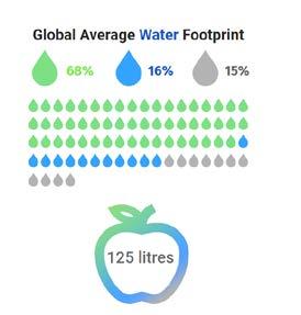
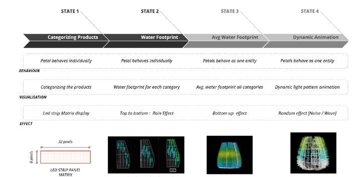
By interacting with Aigua Invisible (Invisible Water) installation, visitors will gain knowledge about water footprints of most common food products consumed every day in Europe, with the source of this water being represented in 3 colors: blue, green, and gray. In order to clearly visualize the idea behind the notion of ‘water footprint’ the structure’s skin is comprised of a multitude plastic bottles. Number of bottles that light up with each showcased product proportionally correspond to its real water footprint in invisible liters. The installation is operating within a concept of data visualization, representing it through a series of dynamic animation sequences with an aim of providing an experience that is both educational and entertaining.
This water is called virtual water, a water that is needed to produce these products, but the one we don’t directly interact with. This water has 3 water footprints: blue – fresh and ground water, green – water that ends up in soils after rains, and gray – polluted water. Each product has its own water footprint that holds a fraction of blue, green or gray ‘flavors’.
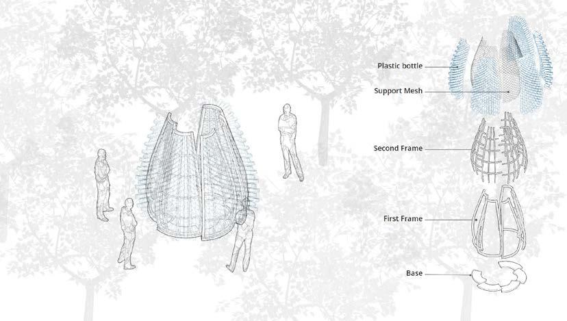
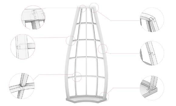
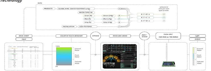
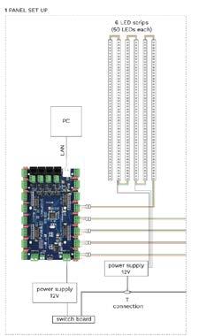
MODULE ASSEMBLY ON SITE PETAL MODULE ASSEMBLY CONNECTIONELECTRICITYASSEMBLY FINAL OUTPUT PETAL WOOD CONSTRUCTION DETAILS CONNECTION BETWEEN BASE SUPPORT & MAINJOINERYFRAMEBETWEEN 2 WOODEN PIECE FOR MAINJOINERYFRAMEBETWEEN 2 WOODEN PIECE FOR MAIN FRAME JOINERY BETWEEN MAIN FRAME & SUB FRAME JOINERY BETWEEN MAIN FRAME & SUB FRAME JOINERY BETWEEN MAIN FRAME & SUB FRAME TECHNOLOGY DETAILS WORKFLOW TO CREATE A DIGITAL OUTPUT FROM A PHYSICAL INPUT ELECTRICAL CONNECTION DETAILS FOR THE MODELUE LIGHT OUTPUT 72 73 FINAL OUTPUT

MAA02 - DESIGN WORKSHOP
74
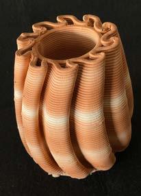
Location worked on computational developed module , generate G-code for robotic printing and material was prepared with some variation in color pigmentation.
:- Institute of Advanced Architecture ROBOTIC CLAY PRINTING
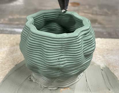

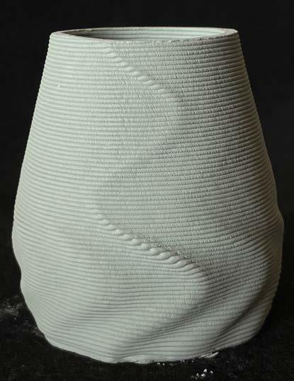
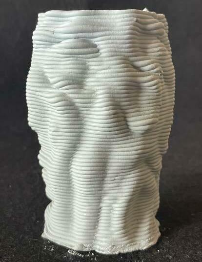
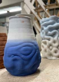
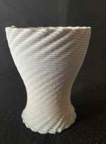

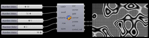
PYTHON WORKSHOP - GRASSHOPPER INTERGRATION CODING
MAA02 - DESIGN WORKSHOP Location :- Institute of Advanced Architecture GREEN NOISE GROUP PROJECTS (worked on concept development with written and oral presenation)
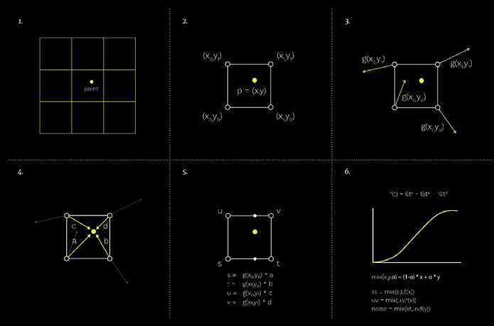
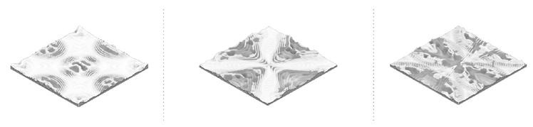
The algorithm for Perlin noise includes following steps: 1. domain subdivided into grid with unit cells; 2.sample point inside the cell; 3. Generate random vectors in the vertices of the cell; 4. calculate vectors from sample points to cell's vertices; 5. dot product for those corresponding vector; 6. apply smoothstep interpolation to the values.
Pseudo Code
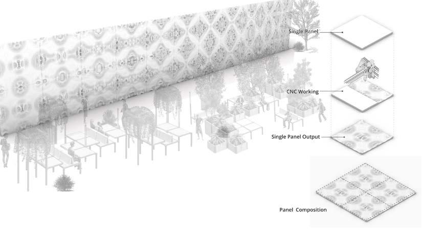
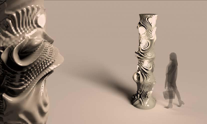
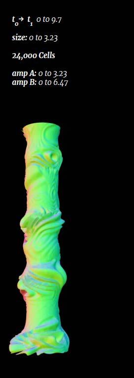
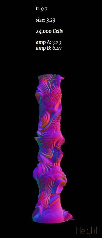
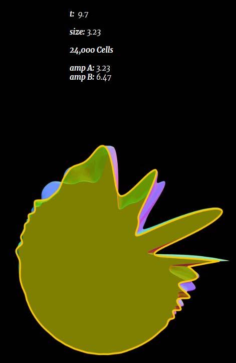
In this project, we start from one of the most famous problems in both math and computer graphics: the n-dimension continuous random distribution, or noise. Noise is usually used for generating texture in CG field. But with the exploration of noise, different variants were invented, such as Perlin Noise or Worley Noise. In the project, we program and realize the algorithm of those different types of noise in Grasshopper with Python and C#. Play with different parameters of the noise and apply them into geometry generation. At the end, with the advanced fabrication tool to bring our design into real.
76
Green noise is a programming project trying to understand and explore the potential of applying math in architecture design. Although current architecture design industry looks like far away from math, it was origin from the same root before. Those elegant ancient buildings like temples or Colosseums were designed based on strong mathematical logics either for structure reason or aesthetics reason.
NOISE ALGORITHMs
Undoubtedly, as designer, we should rethink the potential of math in designing. The modern powerful computing ability of computer bring people into a new age to explore the world. Even though the complex problem required billion calculations could be solve easily in a second, which means people will have the opportunity to explore the aesthetic value that hidden by a more complex mathematical problem.
The pseudo code shows the workflow that how to generate and apply the Perlin noise into the 3D geometry modelling. By UV mapping the input geometry, the based grid for generating Perlin noise is obtained. Apply the Perlin noise algorithm to generate the random values that later will used for modifying the geometry.
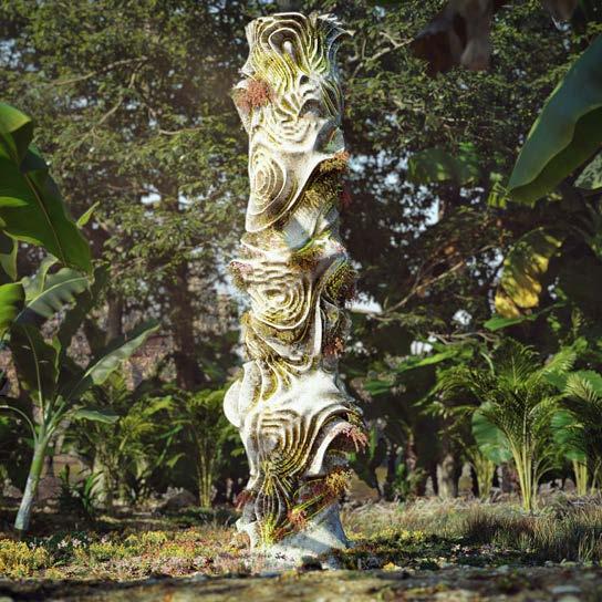

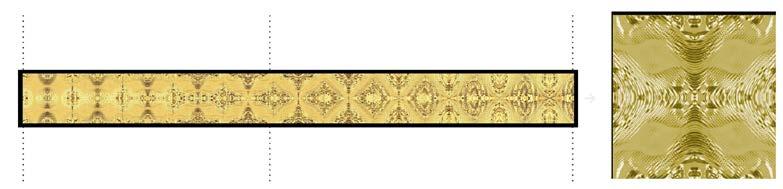
Iteration - 1 t ampamp24000Size1.6180.2cellsA:0B:3.23 Iteration - 5 t ampamp24000Size4.852:0.2cellsA:2.85B:3.24 Iteration - 6 t ampamp24000Size6.470:0.2cellsA:4.85B:6.47 FINAL OUTPUT FABRICATION PROCESS FOR NOISE PANELS CATALOGUE OF NOISE PANELS DESIGN OPTION - 1 - INTERIOR PANEL DESIGN OPTION - 2 - COLUMN FINAL OUTPUT Iteration - 1 t ampamp24000Size1.6180.2cellsA:0B:3.23 Iteration - 5 t : ampamp24000Size4.8520.2cellsA2.85B3.24 Iteration - 6 t ampamp24000Size6.470:0.2cellsA:4.85B:6.47 Iteration - 1 Iteration - 2 Top view section of Iteration - 2 78
Please do contact me at the below email id lekha.g111992@gmail.com
THANK YOU LEKHA GAJBHIYE