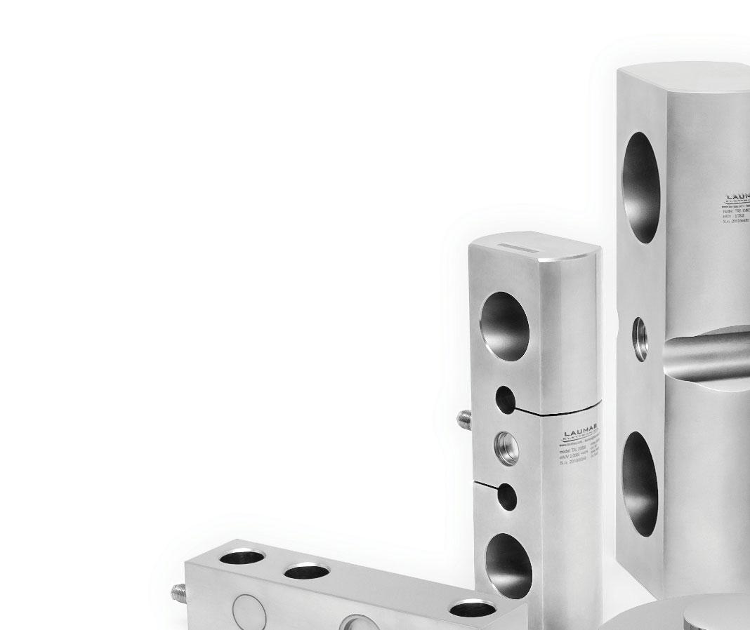
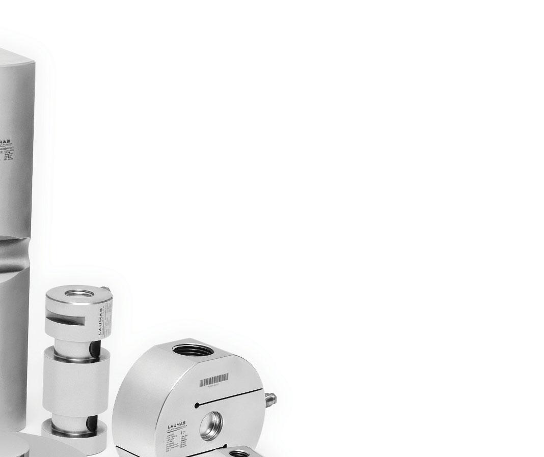
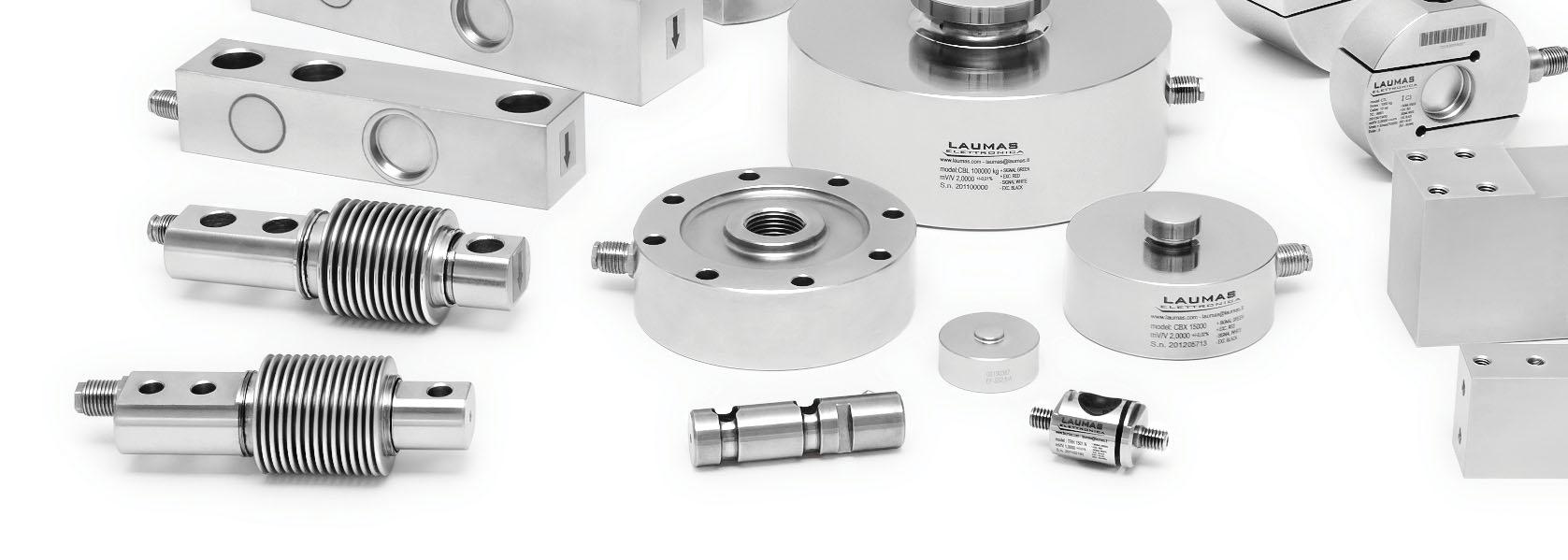
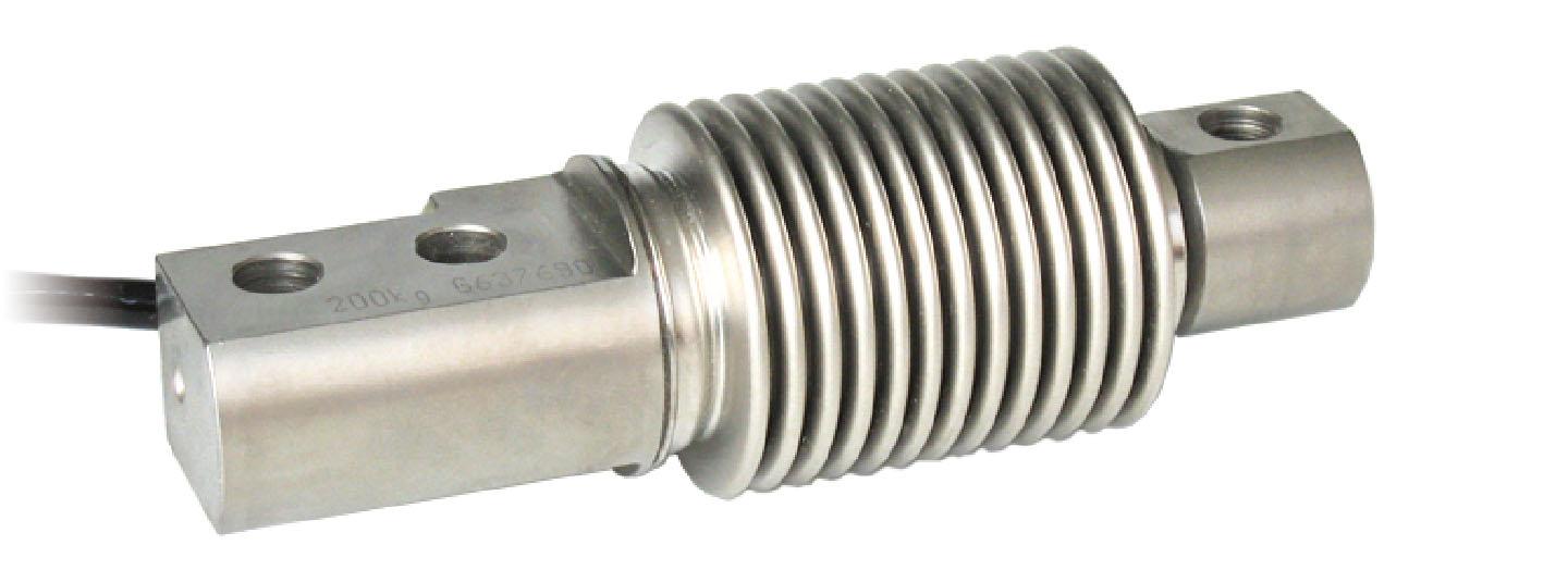
LAUMASoffersawiderangeofloadcellsofthemost commontypesinthemainindustrialsectorsprovidingfor eachofthemthequality,availabilityandassistance.
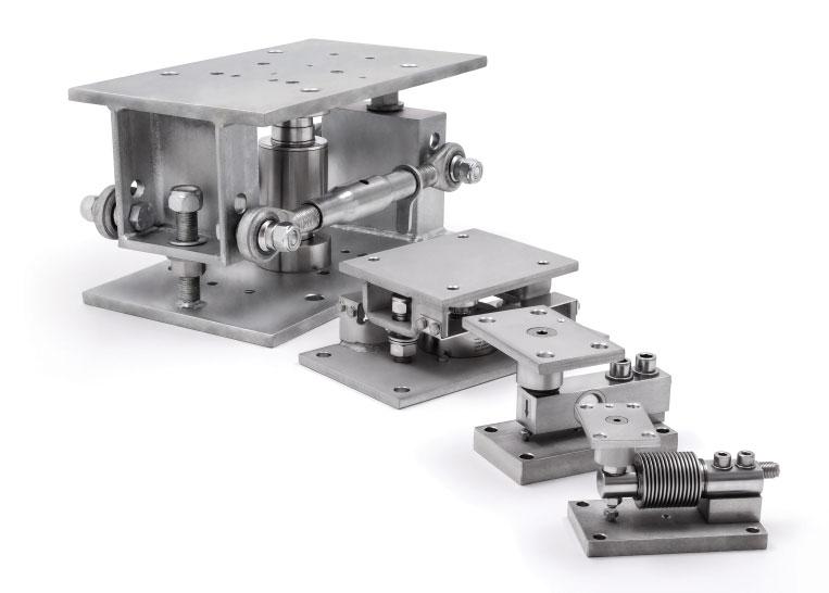
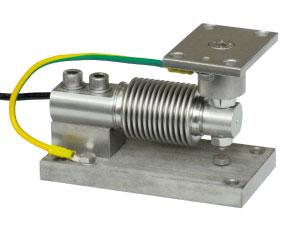
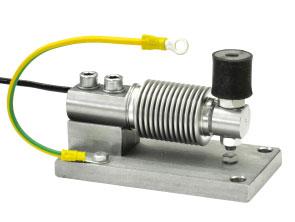
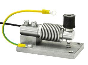
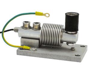
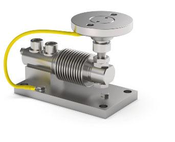
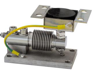
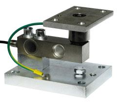
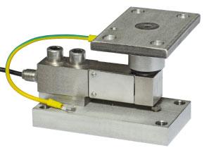
Forallloadcells,LAUMASisabletoprovidesuitable mountingkits,withtheaimofobtainingthecorrect applicationofthecellandmaximumreliabilityandaccuracy, andcompatiblywiththemechanical,electricaland pneumaticconnectionspresentontheweighingstructure.
European Conformity Mark (CE)UKCA CERTIFICATION (UK Conformity Assessed) for the United Kingdom
EAC CERTIFICATION
OIML APPROVALEU TYPE EXAMINATION CERTIFICATE FOR UK Non-Automatic Weighing Instruments (NAWI)
3-A SANITARY STANDARDS
NTEP CERTIFICATIONATEX CERTIFICATION
EAC Ex CERTIFICATION
CPA CERTIFICATION (Chinese Pattern Approval)
Ex NEPSI CERTIFICATION
FM HazLoc (Hazardous Locations) CERTIFICATION
IECEx CERTIFICATION
PAC CERTIFICATION (Pattern Approval Certificate)
EN1090DECLARATION OF CONFORMITY
IP69K MARKING PROTECTION RATING
Testing, calibration, quality control
Calibration services accredited by Accredia for load cells and load cells + instrument, performed in our laboratory LAT No. 02141 for force values between 2 and 100 kN, according to UNI EN ISO 376 and ASTM E74 standards. Accredia is the Sole National accreditation body (European Regulation 765/2008) and guarantees compliance with standards and the reliability of conformity certificates issued on the market. The Accredia calibration certificate is an official document recognized worldwide because it is covered by the EA, IAF, and ILAC Mutual Recognition Agreements. In our laboratory, we also perform calibration reports for force values between 0.5 and 5000 kN (compression) and between 0.5 and 600 kN (tension).

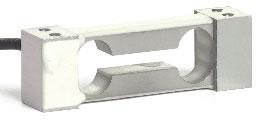
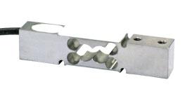


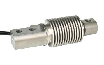
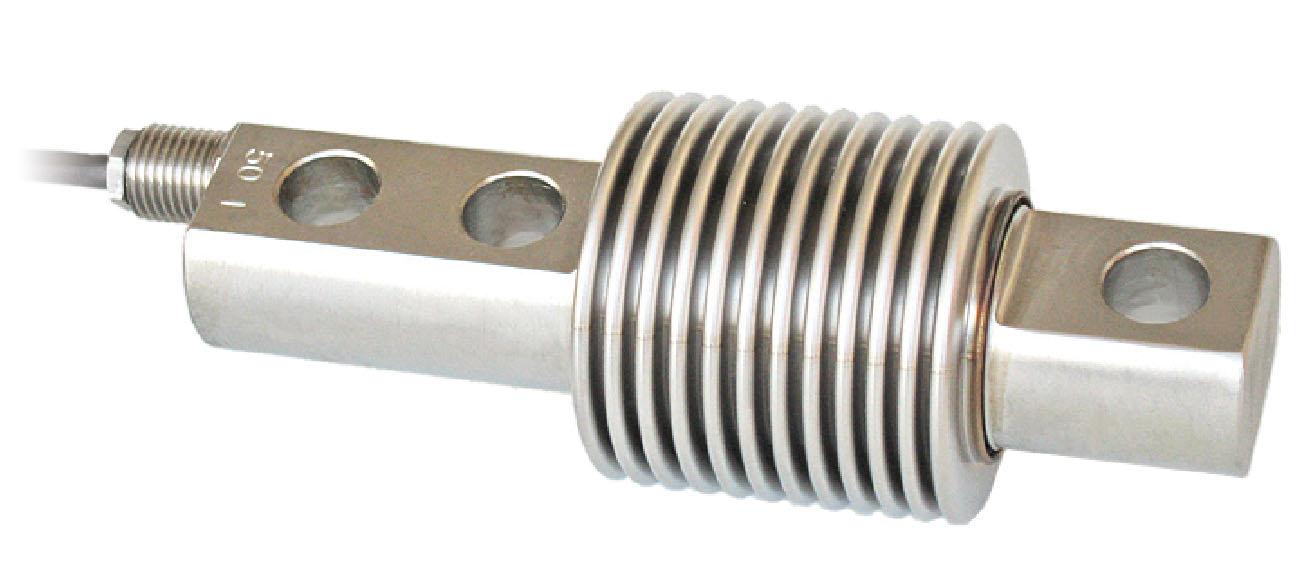
ManufacturedaccordingtoOIMLR60standards
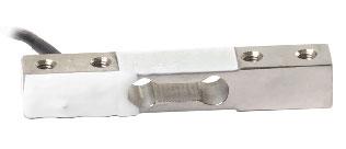
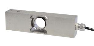
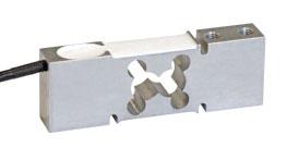
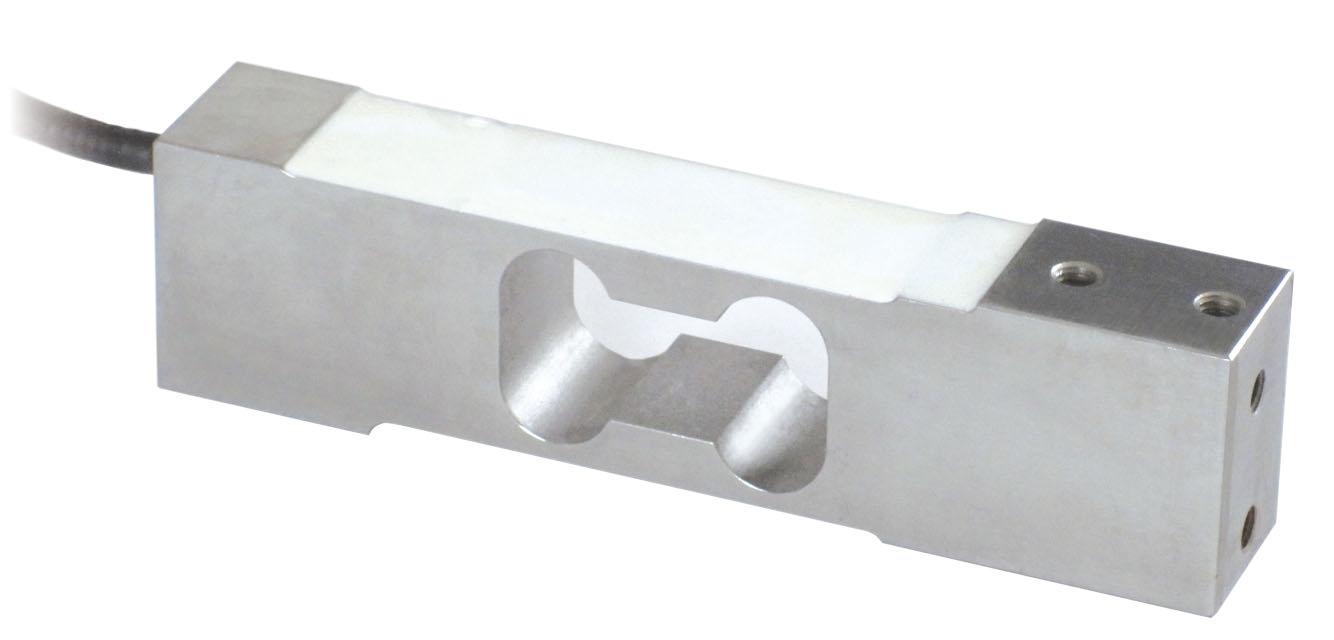
Capacity from 5 kg to 50 kg

CERTIFICATIONS
ComplieswiththeEurasianCustomsUnionregulations
EquivalentoftheCEmarkingfortheUnitedKingdom
CERTIFICATIONS ON REQUEST
Calibrationreport
ATEXII1G2D (zone 0-1-2-21-22) (-)
IECEx (zone 0-1-2-20-21-22)
ComplieswiththeEurasianCustomsUnionregulationsforuseinpotentiallyexplosiveatmospheres
ComplieswithChinesemarketregulationsforuseinpotentiallyexplosiveatmospheres
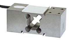
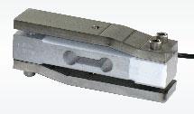
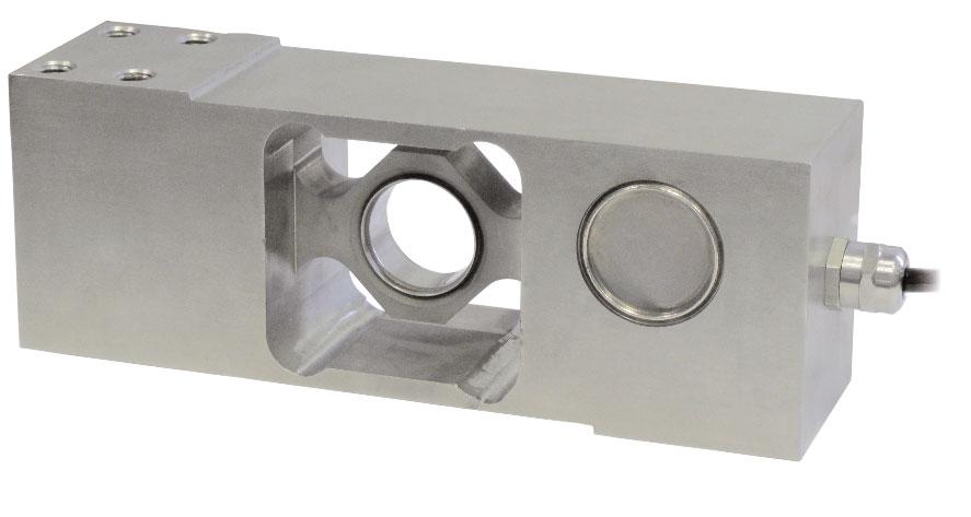
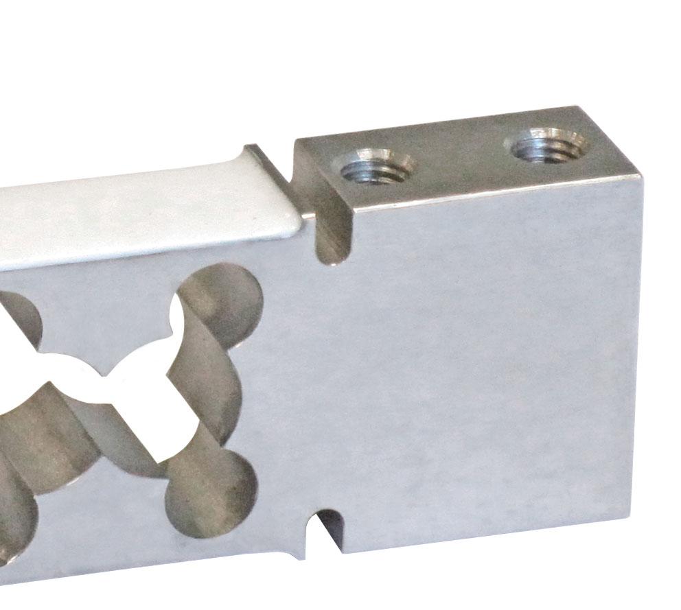
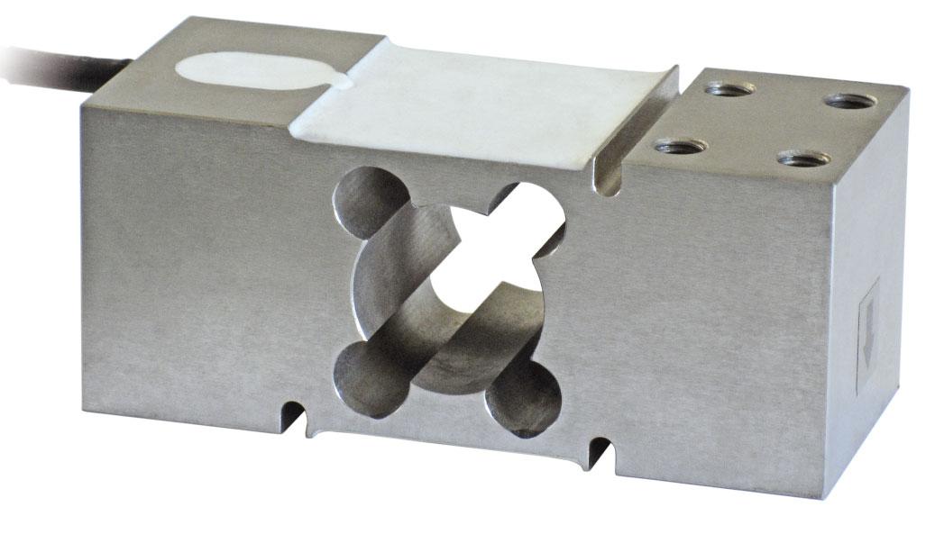
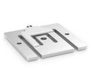
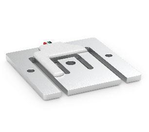
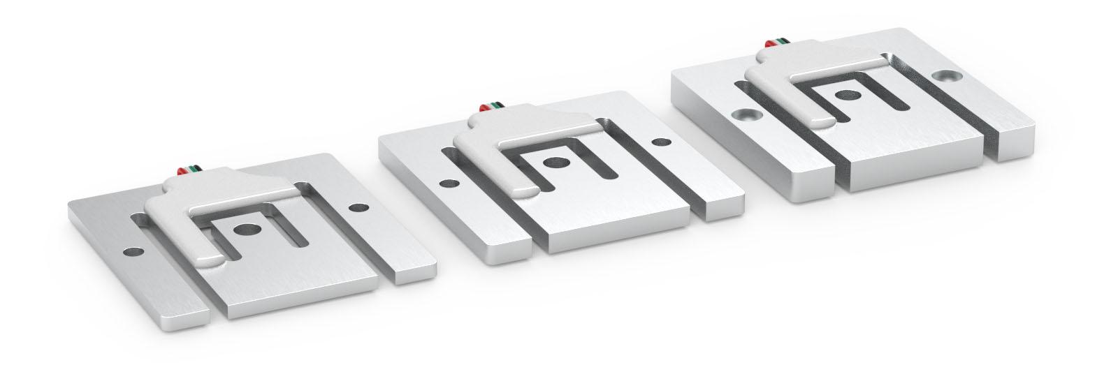
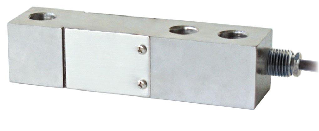
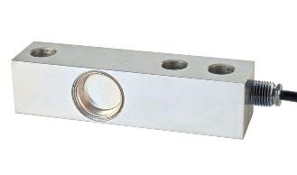
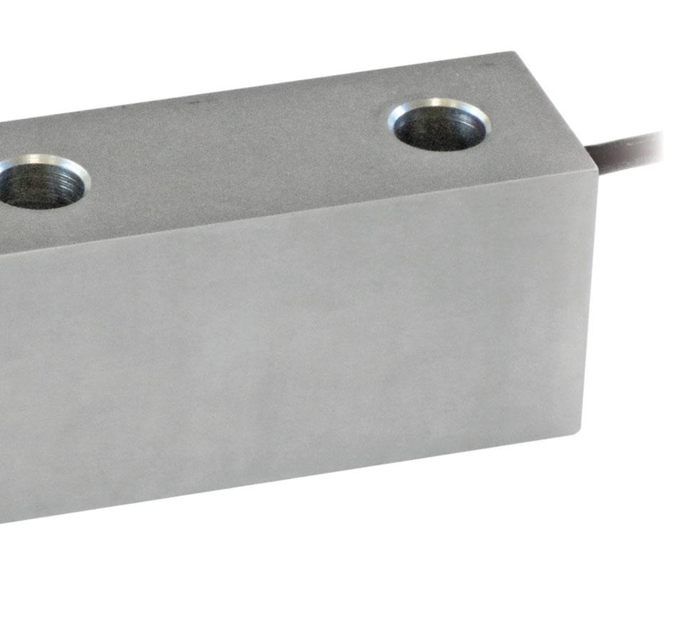
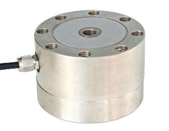
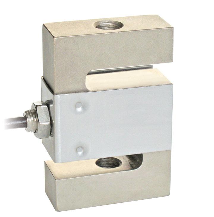
MOUNTING SURFACE MOUNTING SURFACE
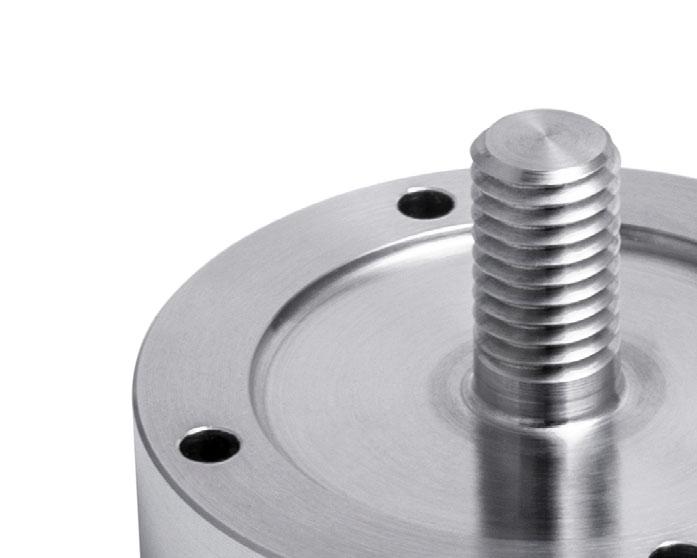
Fortheloadcellfixingscrews,providethetightening torqueindicatedinthetable
Screw
Screwclass Tighteningtorque
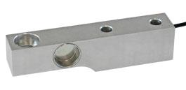
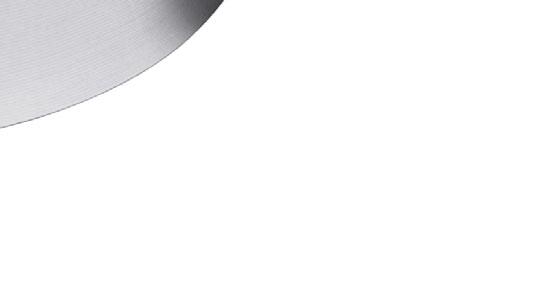
TECHNICAL FEATURES
MaterialAISI420stainlesssteel
Nominalload(Emax)
Combinederror
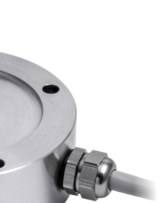
Protectionrating
RatedoutputInputresistance
TemperatureeffectonzeroOutputresistance
TemperatureeffectonspanZerobalance
CompensatedtemperaturerangeInsulationresistance
OperatingtemperaturerangeSafeoverload(%offullscale)
Creepatnominalloadin30minutesUltimateoverload(%offullscale)
MaxsupplyvoltagewithoutdamageDeflectionatnominalload
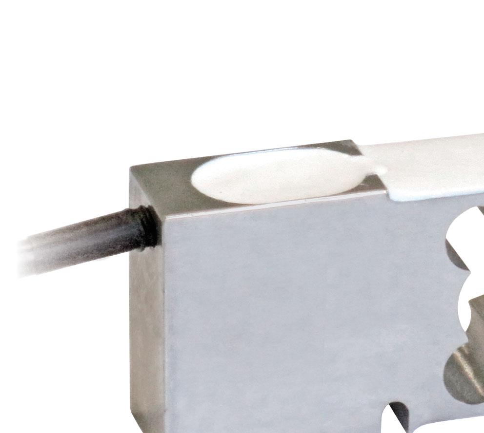
ELECTRICAL CONNECTIONS
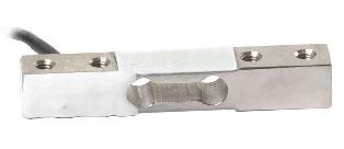
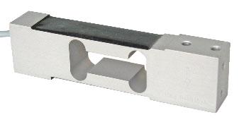
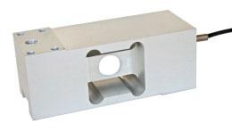
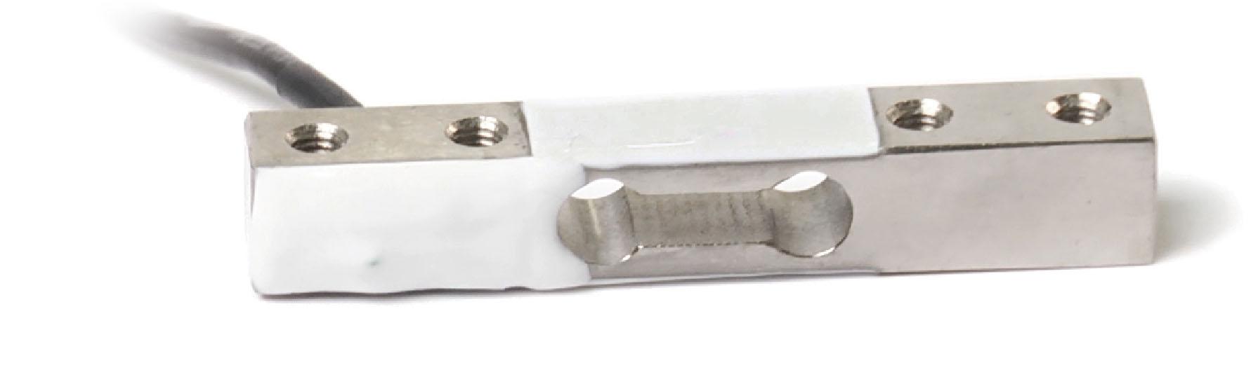
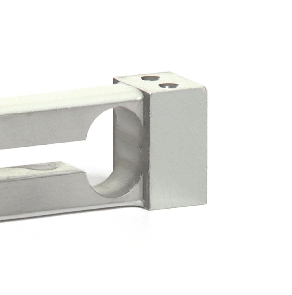
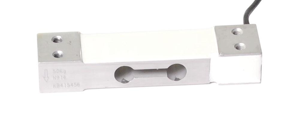
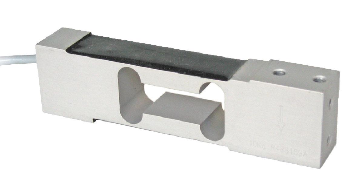
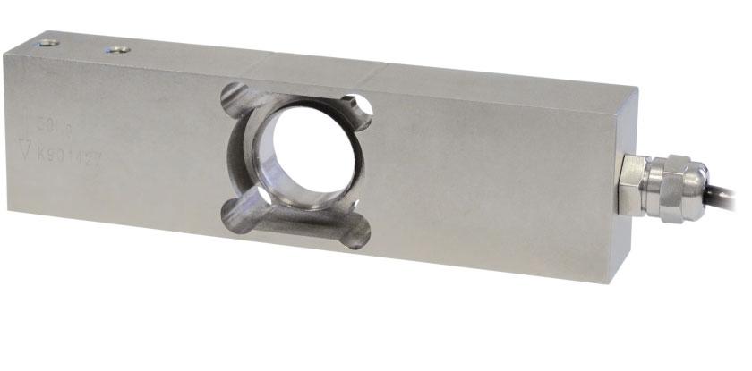
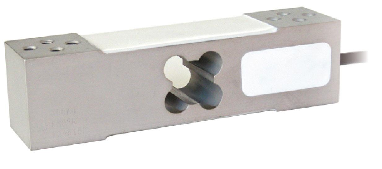
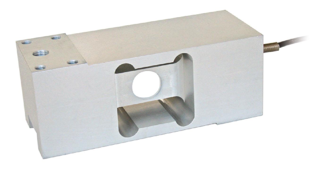
ManufacturedaccordingtoOIMLR60standards
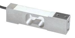
Capacity from 0.25 kg to 1 kg
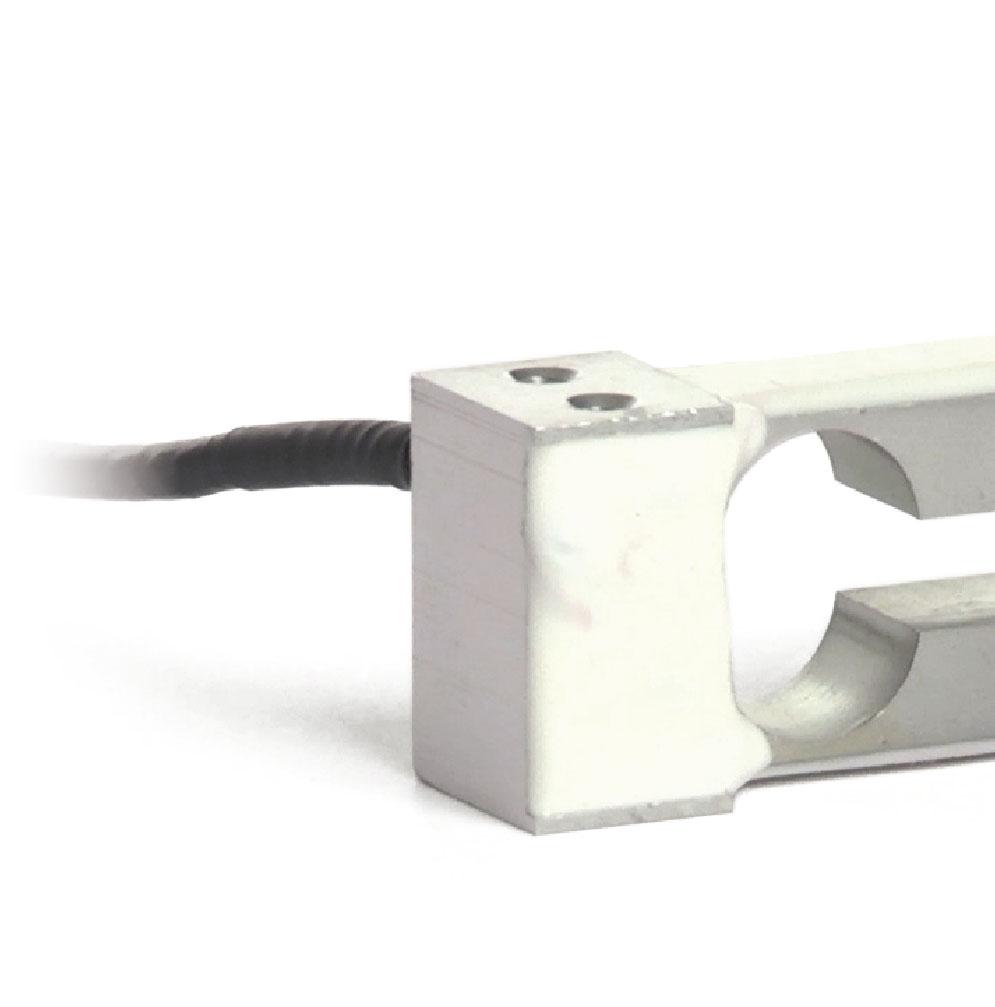
ALUMINUMALLOY COMBINEDERROR±0.03% IP65PROTECTIONRATING

CERTIFICATIONS
ComplieswiththeEurasianCustomsUnionregulations
EquivalentoftheCEmarkingfortheUnitedKingdom
CERTIFICATIONS ON REQUEST
Calibrationreport
ATEXII1G2D (zone 0-1-2-21-22) (-)
IECEx (zone 0-1-2-20-21-22)
ComplieswiththeEurasianCustomsUnionregulationsforuseinpotentiallyexplosiveatmospheres
ComplieswithChinesemarketregulationsforuseinpotentiallyexplosiveatmospheres
Fortheloadcellfixingscrews,providethetightening torqueindicatedinthetable
Screw
Screwclass
Tighteningtorque
TECHNICAL FEATURES
MaterialAluminumalloy
Nominalload(Emax)
Combinederror
Protectionrating
RatedoutputInputresistance
TemperatureeffectonzeroOutputresistance
TemperatureeffectonspanZerobalance
CompensatedtemperaturerangeInsulationresistance
OperatingtemperaturerangeSafeoverload(%offullscale)
Creepatnominalloadin30minutesUltimateoverload(%offullscale)
MaxsupplyvoltagewithoutdamageDeflectionatnominalload
ELECTRICAL CONNECTIONS CablelengthSHIELD

OIMLR60C3
ComplieswiththeEurasianCustomsUnionregulations
EquivalentoftheCEmarkingfortheUnitedKingdom
ComplieswithUnitedKingdomregulationsforlegalfortradeuse
CERTIFICATIONS ON REQUEST
Calibrationreport
ATEXII1G2D (zone 0-1-2-21-22) (-)
IECEx (zone 0-1-2-20-21-22)
OIMLR60C4/C5
ComplieswiththeEurasianCustomsUnionregulationsforuseinpotentiallyexplosiveatmospheres
ComplieswithChinesemarketregulationsforuseinpotentiallyexplosiveatmospheres
NTEP-ComplieswithUnitedStatesregulationsforlegalfortradeuse
COMPLEMENTARY ACCESSORIES
DESCRIPTION
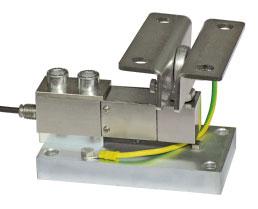
Pairofstainlesssteeltensionbrackets. Maximumstaticload:50kg.
TECHNICAL FEATURES
OIMLR60Accuracyclass•Verificationintervals
Nominalload(Emax)
Minimumverificationinterval(Vmin)
Combinederror
Protectionrating
Fortheloadcellfixingscrews,providethetightening torqueindicatedinthetable Screw
Screwclass Tighteningtorque
C3•3000C4•4000C5•5000 3-5-10-15-20-30-50kg
Emax/10000Emax/15000Emax/20000 ±0.02%±0.017%±0.014% IP65
RatedoutputInputresistance
TemperatureeffectonzeroOutputresistance
TemperatureeffectonspanZerobalance
CompensatedtemperaturerangeInsulationresistance
OperatingtemperaturerangeSafeoverload(%offullscale)
2mV/V±10%409±6 0.001%°C350±3 0.001%°C±2% -10°C/+40°C5000M -35°C/+65°C150%
Creepatnominalloadin30minutesUltimateoverload(%offullscale)
MaxsupplyvoltagewithoutdamageDeflectionatnominalload
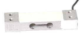
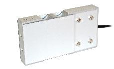
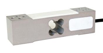
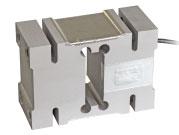
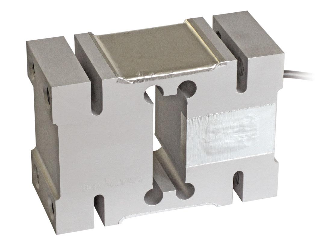
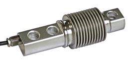
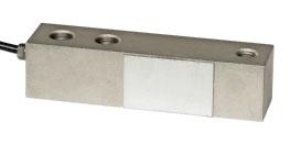
ManufacturedaccordingtoOIMLR60standards
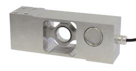
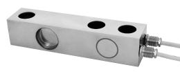
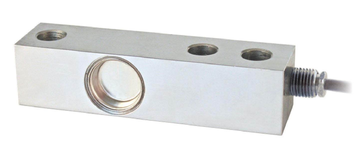
Capacity from 6 kg to 50 kg

AISI420STAINLESSSTEEL COMBINEDERROR±0.02% IP67PROTECTIONRATING
CERTIFICATIONS
ComplieswiththeEurasianCustomsUnionregulations
EquivalentoftheCEmarkingfortheUnitedKingdom
CERTIFICATIONS ON REQUEST
Calibrationreport
ATEXII1G2D (zone 0-1-2-21-22) (-)
IECEx (zone 0-1-2-20-21-22)
ComplieswiththeEurasianCustomsUnionregulationsforuseinpotentiallyexplosiveatmospheres
ComplieswithChinesemarketregulationsforuseinpotentiallyexplosiveatmospheres
COMPLEMENTARY ACCESSORIES
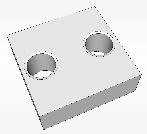
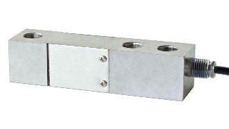
DESCRIPTIONCODE Stainlesssteeldrawnblock.
Fortheloadcellfixingscrews,providethetightening
torqueindicatedinthetable
Screw
Screwclass
Tighteningtorque
TECHNICAL FEATURES
MaterialAISI420stainlesssteel
Nominalload(Emax)
Combinederror
Protectionrating
RatedoutputInputresistance
TemperatureeffectonzeroOutputresistance
TemperatureeffectonspanZerobalance
CompensatedtemperaturerangeInsulationresistance
OperatingtemperaturerangeSafeoverload(%offullscale)
Creepatnominalloadin30minutesUltimateoverload(%offullscale)
MaxsupplyvoltagewithoutdamageDeflectionatnominalload
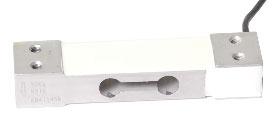
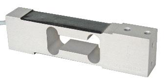
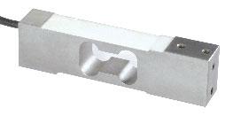
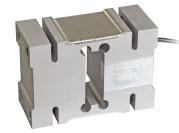
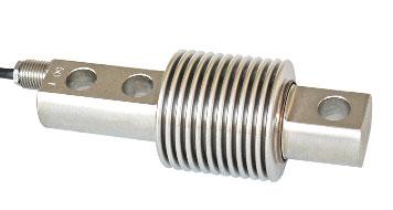
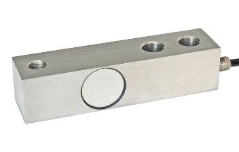
ManufacturedaccordingtoOIMLR60standards
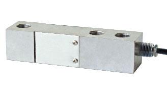
ALUMINUMALLOY COMBINEDERROR±0.02% IP65PROTECTIONRATING
CERTIFICATIONS
ComplieswiththeEurasianCustomsUnionregulations
EquivalentoftheCEmarkingfortheUnitedKingdom
CERTIFICATIONS ON REQUEST
Calibrationreport
ATEXII1G2D (zone 0-1-2-21-22) (-)
IECEx (zone 0-1-2-20-21-22)
ComplieswiththeEurasianCustomsUnionregulationsforuseinpotentiallyexplosiveatmospheres
ComplieswithChinesemarketregulationsforuseinpotentiallyexplosiveatmospheres
DIMENSIONS (mm)
Fortheloadcellfixingscrews,providethetighteningtorqueindicatedinthetable
Screw
Screwclass Tighteningtorque
TECHNICAL FEATURES
MaterialAluminumalloy
Nominalload(Emax)
Combinederror
Protectionrating
RatedoutputInputresistance
TemperatureeffectonzeroOutputresistance
TemperatureeffectonspanZerobalance
CompensatedtemperaturerangeInsulationresistance
OperatingtemperaturerangeSafeoverload(%offullscale)
Creepatnominalloadin30minutesUltimateoverload(%offullscale)
MaxsupplyvoltagewithoutdamageDeflectionatnominalload
ELECTRICAL CONNECTIONS
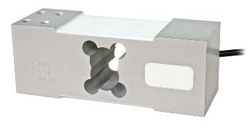
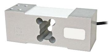
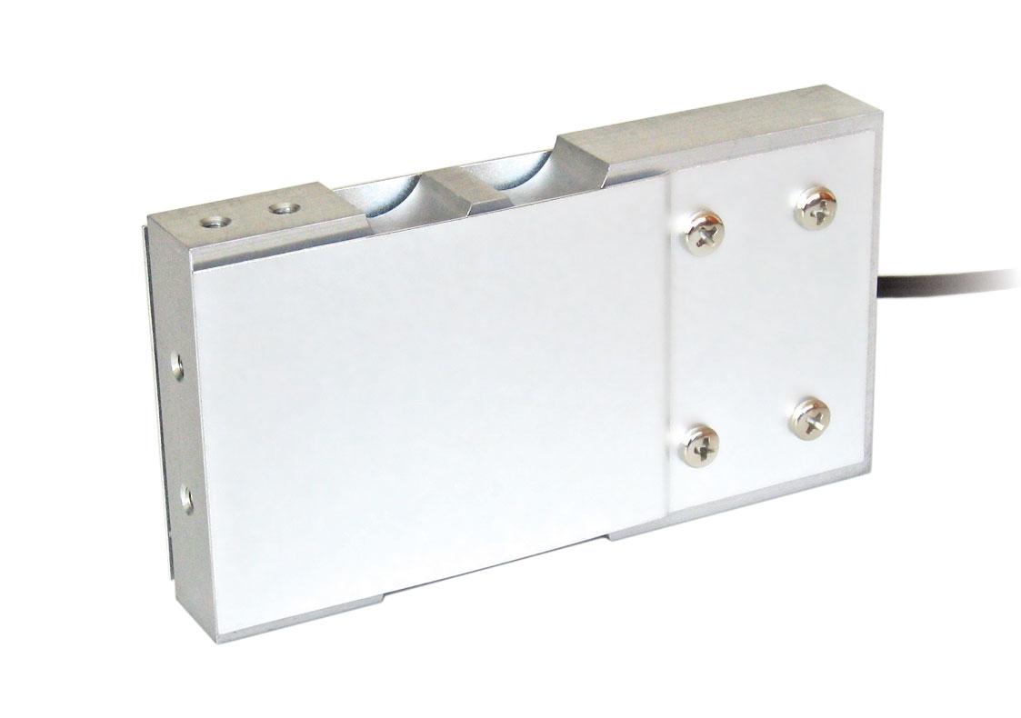
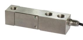
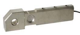
Capacity from 10 kg to 100 kg
ALUMINUMALLOY COMBINEDERROR±0.02%(0.017%C4) IP65PROTECTIONRATING
CERTIFICATIONS
OIMLR60C3
ComplieswiththeEurasianCustomsUnionregulations
EquivalentoftheCEmarkingfortheUnitedKingdom
ComplieswithUnitedKingdomregulationsforlegalfortradeuse
CERTIFICATIONS ON REQUEST
Calibrationreport
ATEXII1G2D (zone 0-1-2-21-22) (-)

Canbeusedforsystemswithatleast 3supports
IECEx (zone 0-1-2-20-21-22)
OIMLR60C4
ComplieswiththeEurasianCustomsUnionregulationsforuseinpotentiallyexplosiveatmospheres
ComplieswithChinesemarketregulationsforuseinpotentiallyexplosiveatmospheres
NTEP-ComplieswithUnitedStatesregulationsforlegalfortradeuse
COMPLEMENTARY ACCESSORIES
DESCRIPTIONCODE Stainlesssteeldrawnblock.
Fortheloadcellfixingscrews,providethetightening torqueindicatedinthetable
Screw Screwclass Tighteningtorque
TECHNICAL FEATURES
MaterialAluminumalloy
OIMLR60Accuracyclass•Verificationintervals
Nominalload(Emax)
Minimumverificationinterval(Vmin)
Combinederror
Protectionrating
C3•3000C4•4000 10-15-20-30-50-100kg15-20-30-50kg Emax/12000Emax/20000 ±0.02%±0.017%
RatedoutputInputresistance
TemperatureeffectonzeroOutputresistance
TemperatureeffectonspanZerobalance
CompensatedtemperaturerangeInsulationresistance
OperatingtemperaturerangeSafeoverload(%offullscale)
Creepatnominalloadin30minutesUltimateoverload(%offullscale)
MaxsupplyvoltagewithoutdamageDeflectionatnominalload
CablelengthSHIELD
Cablediameter+SIGNALGREEN Cores+EXCITATION +REF./SENSE RED BLUE -SIGNALWHITE -EXCITATION -REF./SENSE BLACK BROWN
Canbeusedforsystemswithatleast 3supports
ON REQUEST
CERTIFICATIONS
ComplieswiththeEurasianCustomsUnionregulations
EquivalentoftheCEmarkingfortheUnitedKingdom
ComplieswithUnitedKingdomregulationsforlegalfortradeuse
CERTIFICATIONS ON REQUEST
Declarationofconformity+IP69Kmarkingprotectionrating
Water protection in case of high-pressure or steam jet cleaning (test: pressurized water is sprayed from a distance of max 150 mm)
Water pressure: 100 bar; temperature: 80 °C; test duration: 250 seconds (reference standard: DIN 40050-9)
Calibrationreport
ATEXII1G2D (zone 0-1-2-21-22) (-)
IECEx (zone 0-1-2-20-21-22)
ComplieswiththeEurasianCustomsUnionregulationsforuseinpotentiallyexplosiveatmospheres
FMHazLoc-ComplieswiththeUnitedStatesandCanadaregulationsforuseinpotentiallyexplosiveatmospheres
ComplieswithChinesemarketregulationsforuseinpotentiallyexplosiveatmospheres
NTEP-ComplieswithUnitedStatesregulationsforlegalfortradeuse
DIMENSIONS (mm)
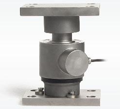
PLATFORM
Fortheloadcellfixingscrews,providethetighteningtorqueindicatedinthetable
Screw
Screwclass Tighteningtorque
TECHNICAL FEATURES
Material17-4PHStainlesssteel
OIMLR60Accuracyclass•Verificationintervals
Nominalload(Emax)
Minimumverificationinterval(Vmin)
Combinederror Protectionrating
C3•3000C4•4000 10-20-50-100-200-300-500kg10-20-50kg Emax/10000Emax/40000 ±0.02%±0.017%
RatedoutputInputresistance
TemperatureeffectonzeroOutputresistance
TemperatureeffectonspanZerobalance
CompensatedtemperaturerangeInsulationresistance
OperatingtemperaturerangeSafeoverload(%offullscale)
Creepatnominalloadin30minutesUltimateoverload(%offullscale)
MaxsupplyvoltagewithoutdamageDeflectionatnominalload
ELECTRICAL CONNECTIONS
CablelengthSHIELD
Cablediameter+SIGNALGREEN Cores+EXCITATION +REF./SENSE RED BLUE -SIGNALWHITE -EXCITATION -REF./SENSE BLACK YELLOW whereprovided
COMPLEMENTARY ACCESSORIES
DESCRIPTIONCODE
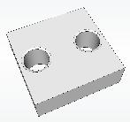
Stainlesssteeldrawnblock forcapacitiesupto50kg.
Stainlesssteeldrawnblock forcapacitiesfrom100to500kg.
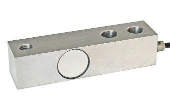
ManufacturedaccordingtoOIMLR60standards
Capacity from 10 kg to 200 kg
MOUNTINGKIT CAPACITY

Canbeusedforsystemswithatleast 3supports
CERTIFICATIONS
ComplieswiththeEurasianCustomsUnionregulations
EquivalentoftheCEmarkingfortheUnitedKingdom
CERTIFICATIONS ON REQUEST
Calibrationreport
ATEXII1G2D (zone 0-1-2-21-22) (-)
IECEx (zone 0-1-2-20-21-22)
ComplieswiththeEurasianCustomsUnionregulationsforuseinpotentiallyexplosiveatmospheres
ComplieswithChinesemarketregulationsforuseinpotentiallyexplosiveatmospheres
COMPLEMENTARY ACCESSORIES
DESCRIPTIONCODE
Stainlesssteeldrawnblock.
Fortheloadcellfixingscrews,providethetightening torqueindicatedinthetable
Screw
Screwclass Tighteningtorque
TECHNICAL FEATURES
MaterialAISI420stainlesssteel
Nominalload(Emax)
Combinederror
Protectionrating
RatedoutputInputresistance
TemperatureeffectonzeroOutputresistance
TemperatureeffectonspanZerobalance
CompensatedtemperaturerangeInsulationresistance
OperatingtemperaturerangeSafeoverload(%offullscale)
Creepatnominalloadin30minutesUltimateoverload(%offullscale)
MaxsupplyvoltagewithoutdamageDeflectionatnominalload
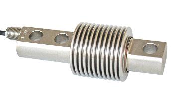
ManufacturedaccordingtoOIMLR60standards
Capacity from 30 kg to 150 kg
CERTIFICATIONS
ComplieswiththeEurasianCustomsUnionregulations
EquivalentoftheCEmarkingfortheUnitedKingdom
CERTIFICATIONS ON REQUEST
Calibrationreport
ATEXII1G2D (zone 0-1-2-21-22) (-)
IECEx (zone 0-1-2-20-21-22)
ComplieswiththeEurasianCustomsUnionregulationsforuseinpotentiallyexplosiveatmospheres
ComplieswithChinesemarketregulationsforuseinpotentiallyexplosiveatmospheres
Fortheloadcellfixingscrews,providethetightening torqueindicatedinthetable
Screw
Screwclass Tighteningtorque
TECHNICAL FEATURES
MaterialAISI420stainlesssteel
Nominalload(Emax)
Combinederror
Protectionrating
RatedoutputInputresistance
TemperatureeffectonzeroOutputresistance
TemperatureeffectonspanZerobalance
CompensatedtemperaturerangeInsulationresistance
OperatingtemperaturerangeSafeoverload(%offullscale)
Creepatnominalloadin30minutesUltimateoverload(%offullscale)
MaxsupplyvoltagewithoutdamageDeflectionatnominalload
MOUNTINGKIT
Canbeusedforsystemswithatleast 3supports
ON REQUEST
CERTIFICATIONS
ComplieswiththeEurasianCustomsUnionregulations
EquivalentoftheCEmarkingfortheUnitedKingdom
ComplieswithUnitedKingdomregulationsforlegalfortradeuse
CERTIFICATIONS ON REQUEST
Calibrationreport
ATEXII1G2D (zone 0-1-2-21-22) (-)
IECEx (zone 0-1-2-20-21-22)
ComplieswiththeEurasianCustomsUnionregulationsforuseinpotentiallyexplosiveatmospheres
ComplieswithChinesemarketregulationsforuseinpotentiallyexplosiveatmospheres
NTEP-ComplieswithUnitedStatesregulationsforlegalfortradeuse
COMPLEMENTARY ACCESSORIES
DESCRIPTIONCODE
Stainlesssteelandrubberwaterproofkit.
Galvanizedsteeldrawnblock.
DIMENSIONS (mm)
TECHNICAL FEATURES ELECTRICAL CONNECTIONS
OIMLR60Accuracyclass•Verificationintervals Nominalload(Emax)
Minimumverificationinterval(Vmin)
Combinederror
Protectionrating
Fortheloadcellfixingscrews,providethetightening torqueindicatedinthetable
Screw
Screwclass
Tighteningtorque
C3•3000C4•4000C5•5000 60-100-150-200-300kg300kg
Emax/10000Emax/15000Emax/20000 ±0.02%±0.017%±0.014%
RatedoutputInputresistance
TemperatureeffectonzeroOutputresistance
TemperatureeffectonspanZerobalance
CompensatedtemperaturerangeInsulationresistance
OperatingtemperaturerangeSafeoverload(%offullscale)
Creepatnominalloadin30minutesUltimateoverload(%offullscale)
MaxsupplyvoltagewithoutdamageDeflectionatnominalload
2mV/V±10%406±6 0.003%°C350±3 0.002%°C±2% -10°C/+40°C5000M -35°C/+65°C150% 0.025%300% 18V0.5mm
ALUMINUMALLOY
COMBINEDERROR±0.02%(0.017%C4) IP65PROTECTIONRATING
CERTIFICATIONS
OIMLR60C3
ComplieswiththeEurasianCustomsUnionregulations
EquivalentoftheCEmarkingfortheUnitedKingdom
ComplieswithUnitedKingdomregulationsforlegalfortradeuse
CERTIFICATIONS ON REQUEST
Calibrationreport
ATEXII1G2D (zone 0-1-2-21-22) (-)
IECEx (zone 0-1-2-20-21-22)
OIMLR60C4
ComplieswiththeEurasianCustomsUnionregulationsforuseinpotentiallyexplosiveatmospheres
ComplieswithChinesemarketregulationsforuseinpotentiallyexplosiveatmospheres
COMPLEMENTARY ACCESSORIES
DESCRIPTIONCODE
Stainlesssteelandrubberwaterproofkit (Ø107x245mmcableglandincluded)
Stainlesssteeldrawnblock. ON REQUEST
Fortheloadcellfixingscrews,providethetightening torqueindicatedinthetable
Screw
Screwclass
Tighteningtorque
TECHNICAL FEATURES
MaterialAluminumalloy
OIMLR60Accuracyclass•Verificationintervals Nominalload(Emax)
Minimumverificationinterval(Vmin)
Combinederror
Protectionrating
RatedoutputInputresistance
C3•3000C4•4000 50-100-150-200-300-500kg150-200-300-500kg Emax/12000Emax/15000 ±0.02%±0.017% IP65 2mV/V±10%409±6
TemperatureeffectonzeroOutputresistance
TemperatureeffectonspanZerobalance
CompensatedtemperaturerangeInsulationresistance
OperatingtemperaturerangeSafeoverload(%offullscale) Creepatnominalloadin30minutesUltimateoverload(%offullscale)
MaxsupplyvoltagewithoutdamageDeflectionatnominalload
ManufacturedaccordingtoOIMLR60standards
Capacity from 75 kg to 500 kg
CERTIFICATIONS
ComplieswiththeEurasianCustomsUnionregulations
EquivalentoftheCEmarkingfortheUnitedKingdom
CERTIFICATIONS ON REQUEST
Calibrationreport
ATEXII1G2D (zone 0-1-2-21-22) (-)
IECEx (zone 0-1-2-20-21-22)
ComplieswiththeEurasianCustomsUnionregulationsforuseinpotentiallyexplosiveatmospheres
ComplieswithChinesemarketregulationsforuseinpotentiallyexplosiveatmospheres
COMPLEMENTARY ACCESSORIES
Fortheloadcellfixingscrews,providethetightening torqueindicatedinthetable
Screw
Screwclass
Tighteningtorque
TECHNICAL FEATURES
MaterialAISI420stainlesssteel
Nominalload(Emax)
Combinederror
Protectionrating
RatedoutputInputresistance
TemperatureeffectonzeroOutputresistance
TemperatureeffectonspanZerobalance
CompensatedtemperaturerangeInsulationresistance
OperatingtemperaturerangeSafeoverload(%offullscale)
Creepatnominalloadin30minutesUltimateoverload(%offullscale)
MaxsupplyvoltagewithoutdamageDeflectionatnominalload
ManufacturedaccordingtoOIMLR60standards
Capacity from 500 kg to 1000 kg
COMBINEDERROR±0.05% IP65PROTECTIONRATING
CERTIFICATIONS
ComplieswiththeEurasianCustomsUnionregulations
EquivalentoftheCEmarkingfortheUnitedKingdom
CERTIFICATIONS ON REQUEST
Calibrationreport
LATAccrediacalibrationcertificateISO376orASTME74forcapacitiesfrom1000kgto10000kg
ATEXII1G2D (zone 0-1-2-21-22) (-)
IECEx (zone 0-1-2-20-21-22)
ComplieswiththeEurasianCustomsUnionregulationsforuseinpotentiallyexplosiveatmospheres
ComplieswithChinesemarketregulationsforuseinpotentiallyexplosiveatmospheres
Fortheloadcellfixingscrews,providethetightening torqueindicatedinthetable
Screw
Screwclass Tighteningtorque
TECHNICAL FEATURES
MaterialAluminumalloy
Nominalload(Emax)
Combinederror
Protectionrating
RatedoutputInputresistance
TemperatureeffectonzeroOutputresistance
TemperatureeffectonspanZerobalance
CompensatedtemperaturerangeInsulationresistance
OperatingtemperaturerangeSafeoverload(%offullscale)
Creepatnominalloadin30minutesUltimateoverload(%offullscale)
MaxsupplyvoltagewithoutdamageDeflectionatnominalload
ELECTRICAL CONNECTIONS
Capacity from 1000 kg to 2000 kg
ALUMINUMALLOY COMBINEDERROR±0.02% IP65PROTECTIONRATING
CERTIFICATIONS
ComplieswiththeEurasianCustomsUnionregulations
EquivalentoftheCEmarkingfortheUnitedKingdom
PLATFORM (mm)
ComplieswithUnitedKingdomregulationsforlegalfortradeuse
CERTIFICATIONS ON REQUEST
Calibrationreport
LATAccrediacalibrationcertificateISO376orASTME74forcapacitiesfrom1000kgto10000kg
ATEXII1G2D (zone 0-1-2-21-22) (-)

IECEx (zone 0-1-2-20-21-22)
ComplieswiththeEurasianCustomsUnionregulationsforuseinpotentiallyexplosiveatmospheres
ComplieswithChinesemarketregulationsforuseinpotentiallyexplosiveatmospheres
Fortheloadcellfixingscrews,providethetightening torqueindicatedinthetable
Screw
Screwclass
Tighteningtorque
TECHNICAL FEATURES
MaterialAluminumalloy
OIMLR60Accuracyclass•Verificationintervals
Nominalload(Emax)
Minimumverificationinterval(Vmin)
Combinederror
Protectionrating
RatedoutputInputresistance
TemperatureeffectonzeroOutputresistance
TemperatureeffectonspanZerobalance
CompensatedtemperaturerangeInsulationresistance
OperatingtemperaturerangeSafeoverload(%offullscale)
Creepatnominalloadin30minutesUltimateoverload(%offullscale)
MaxsupplyvoltagewithoutdamageDeflectionatnominalload
ELECTRICAL CONNECTIONS
ManufacturedaccordingtoOIMLR60standards
Capacity from 22 kg to 110 kg
ANODIZEDALUMINUMALLOY COMBINEDERROR±0.023% IP65PROTECTIONRATING
CERTIFICATIONS
EquivalentoftheCEmarkingfortheUnitedKingdom
CERTIFICATIONS ON REQUEST
DIMENSIONS (mm)
TECHNICAL FEATURES
MaterialAnodizedaluminumalloy
Minimumverificationinterval(Vmin)
Combinederror
Protectionrating
RatedoutputInputresistance
TemperatureeffectonzeroOutputresistance
TemperatureeffectonspanZerobalance
CompensatedtemperaturerangeInsulationresistance
OperatingtemperaturerangeSafeoverload(%offullscale)
Creepatnominalloadin30minutesUltimateoverload(%offullscale)
MaxsupplyvoltagewithoutdamageDeflectionatnominalload
ELECTRICAL CONNECTIONS

ManufacturedaccordingtoOIMLR60standards
Capacity from 5 kg to 10 kg
17-4PHSTAINLESSSTEEL COMBINEDERROR±0.02% IP68PROTECTIONRATING
CERTIFICATIONS
ComplieswiththeEurasianCustomsUnionregulations
EquivalentoftheCEmarkingfortheUnitedKingdom
CERTIFICATIONS ON REQUEST
Calibrationreport
ATEXII1G2D (zone 0-1-2-21-22) (-)
MOUNTINGKITS

IECEx (zone 0-1-2-20-21-22)
ComplieswiththeEurasianCustomsUnionregulationsforuseinpotentiallyexplosiveatmospheres
ComplieswithChinesemarketregulationsforuseinpotentiallyexplosiveatmospheres
COMPLEMENTARY ACCESSORIES
DESCRIPTIONCODE


Pairoftensionstainlesssteelbrackets. Maximumstaticload:100kg
DIMENSIONS (mm)
Fortheloadcellfixingscrews,providethetightening torqueindicatedinthetable
Screw Screwclass Tighteningtorque
TECHNICAL FEATURES
Material17-4PHstainlesssteel
Nominalload(Emax)
Combinederror Protectionrating
RatedoutputInputresistance
TemperatureeffectonzeroOutputresistance
TemperatureeffectonspanZerobalance
CompensatedtemperaturerangeInsulationresistance
OperatingtemperaturerangeSafeoverload(%offullscale)
Creepatnominalloadin30minutesUltimateoverload(%offullscale)
MaxsupplyvoltagewithoutdamageDeflectionatnominalload
ELECTRICAL CONNECTIONS CablelengthSHIELD Cablediameter+SIGNALGREEN Cores+EXCITATIONRED
Capacity from 20 kg to 500 kg
17-4PHSTAINLESSSTEEL COMBINEDERROR±0.02%(0.017%C4)
IP68PROTECTIONRATING
CERTIFICATIONS
OIMLR60C3
ON REQUEST
ComplieswiththeEurasianCustomsUnionregulations
EquivalentoftheCEmarkingfortheUnitedKingdom
ComplieswithUnitedKingdomregulationsforlegalfortradeuse
CERTIFICATIONS ON REQUEST
Calibrationreport
ATEXII1G2D (zone 0-1-2-21-22) (-)
IECEx (zone 0-1-2-20-21-22)
OIMLR60C4
ComplieswiththeEurasianCustomsUnionregulationsforuseinpotentiallyexplosiveatmospheres
FMHazLoc-ComplieswiththeUnitedStatesandCanadaregulationsforuseinpotentiallyexplosiveatmospheres
ComplieswithChinesemarketregulationsforuseinpotentiallyexplosiveatmospheres
NTEP-ComplieswithUnitedStatesregulationsforlegalfortradeuse
DESCRIPTIONCODE


Pairoftensionstainlesssteelbrackets. Maximumstaticload:100kg
DIMENSIONS (mm) TENSIONSTAINLESSSTEEL BRACKETS
MOUNTING SURFACE
Fortheloadcellfixingscrews,providethetighteningtorqueindicatedinthetable
Screw
Screwclass Tighteningtorque
TECHNICAL FEATURES
Material17-4PHstainlesssteel
OIMLR60Accuracyclass•Verificationintervals
Nominalload(Emax)
Minimumverificationinterval(Vmin)
Combinederror
Protectionrating
C3•3000C4•4000 20-50-100-200-350-500kg Emax/10000Emax/15000 ±0.02%±0.017%
RatedoutputInputresistance
TemperatureeffectonzeroOutputresistance
TemperatureeffectonspanZerobalance
CompensatedtemperaturerangeInsulationresistance
OperatingtemperaturerangeSafeoverload(%offullscale)
Creepatnominalloadin30minutesUltimateoverload(%offullscale)
MaxsupplyvoltagewithoutdamageDeflectionatnominalload
Calibratedcurrentoutput
ELECTRICAL CONNECTIONS
ManufacturedaccordingtoOIMLR60standards
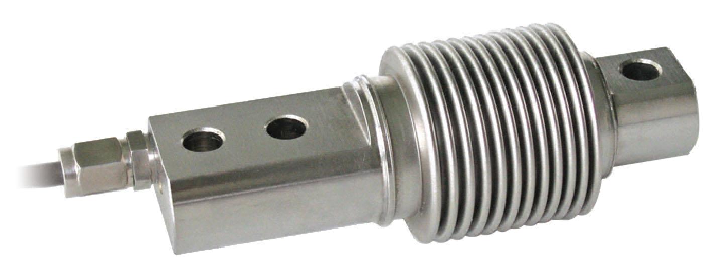
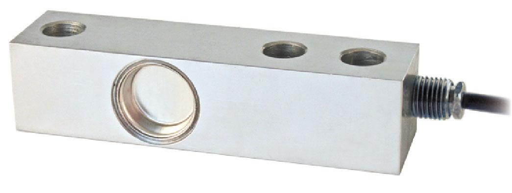
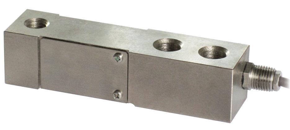
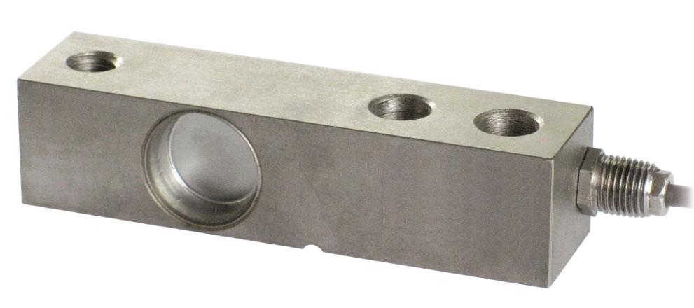
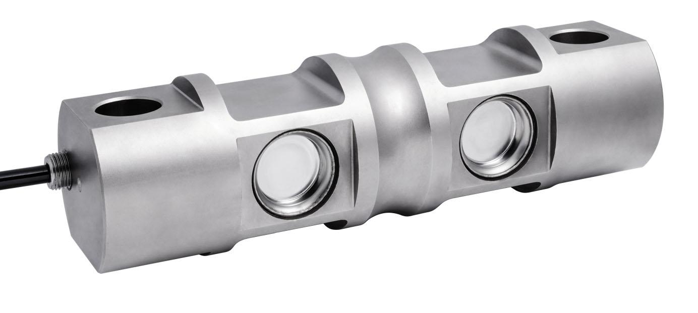
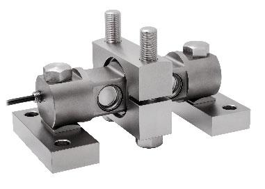
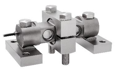
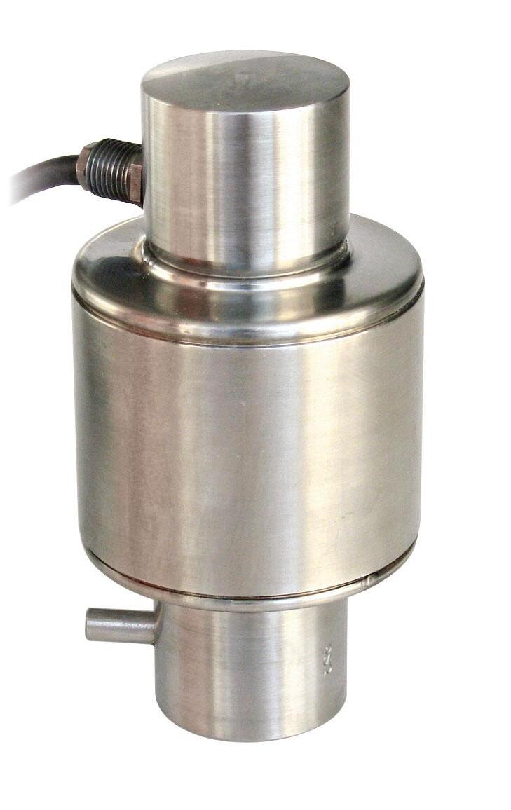
BENDING BEAM: capacity from 30 kg to 500 kg
SHEAR BEAM: capacity from 750 kg to 1500 kg
AISI420STAINLESSSTEEL COMBINEDERROR±0.02% IP68PROTECTIONRATING
MOUNTINGKITS
CERTIFICATIONS
ComplieswiththeEurasianCustomsUnionregulations
EquivalentoftheCEmarkingfortheUnitedKingdom
CERTIFICATIONS ON REQUEST
Calibrationreport
LATAccrediacalibrationcertificateISO376orASTME74forcapacitiesfrom1000kgto10000kg
ATEXII1G2D (zone 0-1-2-21-22) (-)
IECEx (zone 0-1-2-20-21-22)
ComplieswiththeEurasianCustomsUnionregulationsforuseinpotentiallyexplosiveatmospheres
ComplieswithChinesemarketregulationsforuseinpotentiallyexplosiveatmospheres
COMPLEMENTARY ACCESSORIES DESCRIPTIONCODE


DIMENSIONS (mm)
Pairoftensionstainlesssteelbrackets. Maximumstaticload:300kg
Fortheloadcellfixingscrews,providethetightening torqueindicatedinthetable
Screw
Screwclass Tighteningtorque
TECHNICAL FEATURES
MaterialAISI420stainlesssteel
Nominalload(Emax)
Combinederror
Protectionrating
RatedoutputInputresistance
TemperatureeffectonzeroOutputresistance
TemperatureeffectonspanZerobalance
CompensatedtemperaturerangeInsulationresistance
OperatingtemperaturerangeSafeoverload(%offullscale)
Creepatnominalloadin30minutesUltimateoverload(%offullscale)
MaxsupplyvoltagewithoutdamageDeflectionatnominalload ELECTRICAL CONNECTIONS
Capacity from 50 kg to 300 kg
AISI420STAINLESSSTEEL COMBINEDERROR±0.017% IP68PROTECTIONRATING
MOUNTINGKITS
CERTIFICATIONS
ComplieswiththeEurasianCustomsUnionregulations
EquivalentoftheCEmarkingfortheUnitedKingdom
ComplieswithUnitedKingdomregulationsforlegalfortradeuse
CERTIFICATIONS ON REQUEST
Calibrationreport
ATEXII1G2D (zone 0-1-2-21-22) (-)
IECEx (zone 0-1-2-20-21-22)
ComplieswiththeEurasianCustomsUnionregulationsforuseinpotentiallyexplosiveatmospheres
ComplieswithChinesemarketregulationsforuseinpotentiallyexplosiveatmospheres
COMPLEMENTARY ACCESSORIES
DESCRIPTIONCODE
Pairoftensionstainlesssteelbrackets. Maximumstaticload:300kg
DIMENSIONS (mm)
Fortheloadcellfixingscrews,providethetightening torqueindicatedinthetable
Screw
Screwclass
Tighteningtorque
TECHNICAL FEATURES
MaterialAISI420stainlesssteel
OIMLR60Accuracyclass•Verificationintervals
Nominalload(Emax)
Minimumverificationinterval(Vmin)
Combinederror
Protectionrating
C3•3000
50-75-150-300kg
Emax/10000 ±0.017%
RatedoutputInputresistance
TemperatureeffectonzeroOutputresistance
TemperatureeffectonspanZerobalance
CompensatedtemperaturerangeInsulationresistance
OperatingtemperaturerangeSafeoverload(%offullscale)
Creepatnominalloadin30minutesUltimateoverload(%offullscale)
MaxsupplyvoltagewithoutdamageDeflectionatnominalload
ELECTRICAL CONNECTIONS
CablelengthSHIELD
Cablediameter+SIGNALGREEN Cores+EXCITATIONRED -SIGNALWHITE -EXCITATIONBLACK
BENDING BEAM: capacity from 75 kg to 300 kg
SHEAR BEAM: capacity from 500 kg to 10000 kg

AISI420STAINLESSSTEEL COMBINEDERROR±0.02% IP67-IP68PROTECTIONRATING
CERTIFICATIONS
OIMLR60C3
ComplieswiththeEurasianCustomsUnionregulations
EquivalentoftheCEmarkingfortheUnitedKingdom
ComplieswithUnitedKingdomregulationsforlegalfortradeuse
CERTIFICATIONS ON REQUEST
Declarationofconformity+IP69Kmarkingprotectionrating
Water protection in case of high-pressure or steam jet cleaning (test: pressurized water is sprayed from a distance of max 150 mm)
Water pressure: 100 bar; temperature: 80 °C; test duration: 250 seconds (reference standard: DIN 40050-9)
Calibrationreport
LATAccrediacalibrationcertificateISO376orASTME74forcapacitiesfrom1000kgto10000kg
ATEXII1G2D (zone 0-1-2-21-22) (-)
IECEx (zone 0-1-2-20-21-22)
ComplieswiththeEurasianCustomsUnionregulationsforuseinpotentiallyexplosiveatmospheres
ComplieswithChinesemarketregulationsforuseinpotentiallyexplosiveatmospheres
ComplieswithChinesemarketregulationsforlegalfortradeuse
DIMENSIONS (mm)
Fortheloadcellfixingscrews,providethetighteningtorqueindicatedinthetable Screw
Screwclass Tighteningtorque
MaterialAISI420stainlesssteel
OIMLR60Accuracyclass•Verificationintervals
Nominalload(Emax)
Minimumverificationinterval(Vmin)
Combinederror
Protectionrating
Inputresistance
Outputresistance
C3•300075-150-300-500-750 1000-1500-2000kg3000-5000-10000kg Emax/15000-
±0.02%
IP67(75-300kg),IP68(500-10000kg)
385±10400±15
350±3350±5
RatedoutputMaxsupplyvoltagewithoutdamage
TemperatureeffectonzeroZerobalance
TemperatureeffectonspanInsulationresistance
CompensatedtemperaturerangeSafeoverload(%offullscale)
OperatingtemperaturerangeUltimateoverload(%offullscale)
Creepatnominalloadin30minutesDeflectionatnominalload
2mV/V±0.4%15V 0.002%°C±2% 0.0012%°C5000M -10°C/+40°C150% -20°C/+70°C200% 0.03%0.4mm
ELECTRICAL CONNECTIONS
CablelengthSHIELD
5m(75-5000kg);10m(10000kg) 5mm 6x0.25mm2
Cablediameter+SIGNALGREEN Cores+EXCITATION +REF./SENSE RED BLUE -SIGNALWHITE -EXCITATION -REF./SENSE BLACK YELLOW
BENDING BEAM: capacity from 75 kg to 300 kgSHEAR BEAM: capacity from 500 kg to 5000 kg
AISI4340NICKELPLATEDSTEEL COMBINEDERROR±0.02% IP67-IP68PROTECTIONRATING

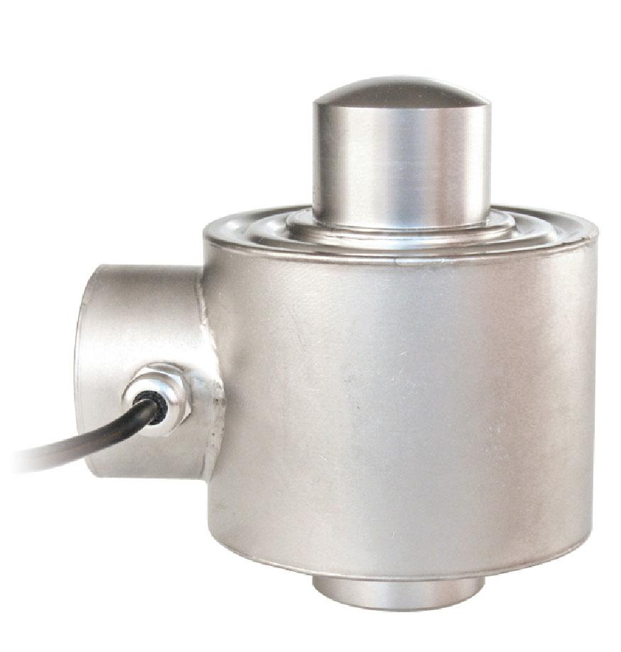
TF500/2000series
CERTIFICATIONS
ComplieswiththeEurasianCustomsUnionregulations
EquivalentoftheCEmarkingfortheUnitedKingdom
ComplieswithUnitedKingdomregulationsforlegalfortradeuse
CERTIFICATIONS ON REQUEST
Calibrationreport
LATAccrediacalibrationcertificateISO376orASTME74forcapacitiesfrom1000kgto10000kg
ATEXII1G2D (zone 0-1-2-21-22) (-)
IECEx (zone 0-1-2-20-21-22)
ComplieswiththeEurasianCustomsUnionregulationsforuseinpotentiallyexplosiveatmospheres
ComplieswithChinesemarketregulationsforuseinpotentiallyexplosiveatmospheres
DIMENSIONS (mm)
Fortheloadcellfixingscrews,providethetighteningtorqueindicatedinthetable Screw
Screwclass Tighteningtorque
TECHNICAL FEATURES
MaterialAISI4340nickelplatedsteel
OIMLR60Accuracyclass•Verificationintervals Nominalload(Emax)
Minimumverificationinterval(Vmin)
Combinederror
Protectionrating
75-150-300-500kg1000-2000-3000-5000kg -Emax/12000 ±0.02%
RatedoutputInputresistance
TemperatureeffectonzeroOutputresistance
TemperatureeffectonspanZerobalance
CompensatedtemperaturerangeInsulationresistance
OperatingtemperaturerangeSafeoverload(%offullscale)
Creepatnominalloadin30minutesUltimateoverload(%offullscale)
IP67(75-300kg),IP68(500-5000kg) 2mV/V±0.1%400±10 0.002%°C352±2 0.0012%°C±2% -10°C/+40°C5000M -20°C/+70°C150% 0.03%250%
MaxsupplyvoltagewithoutdamageDeflectionatnominalload
CablelengthSHIELD Cablediameter+SIGNALGREEN Cores+EXCITATION +REF./SENSE RED BLUE -SIGNALWHITE -EXCITATION -REF./SENSE BLACK YELLOW/BROWN
DESCRIPTIONCODE
Specialsteelblock forcapacitiesupto2000kg.
Capacity from 300 kg to 2000 kg
17-4PHSTAINLESSSTEEL COMBINEDERROR±0.02% IP68PROTECTIONRATING
MOUNTINGKITS CAPACITY
CLASS
CERTIFICATIONS
OIMLR60C3
ComplieswiththeEurasianCustomsUnionregulations
EquivalentoftheCEmarkingfortheUnitedKingdom
ComplieswithUnitedKingdomregulationsforlegalfortradeuse
CERTIFICATIONS ON REQUEST
Declarationofconformity+IP69Kmarkingprotectionrating
Water protection in case of high-pressure or steam jet cleaning (test: pressurized water is sprayed from a distance of max 150 mm)
TFPS2000series
TF500/2000series
IP69K
Water pressure: 100 bar; temperature: 80 °C; test duration: 250 seconds (reference standard: DIN 40050-9)
Calibrationreport
LATAccrediacalibrationcertificateISO376orASTME74forcapacitiesfrom1000kgto10000kg
ATEXII1G2D (zone 0-1-2-21-22) (-)
IECEx (zone 0-1-2-20-21-22)
ComplieswiththeEurasianCustomsUnionregulationsforuseinpotentiallyexplosiveatmospheres
ComplieswithChinesemarketregulationsforuseinpotentiallyexplosiveatmospheres
DIMENSIONS (mm)
Fortheloadcellfixingscrews,providethetightening torqueindicatedinthetable
Screw
Screwclass
Tighteningtorque
TECHNICAL FEATURES
Material17-4PHstainlesssteel
OIMLR60Accuracyclass•Verificationintervals
Nominalload(Emax)
Minimumverificationinterval(Vmin)
Combinederror
Protectionrating
RatedoutputInputresistance
TemperatureeffectonzeroOutputresistance
TemperatureeffectonspanZerobalance
CompensatedtemperaturerangeInsulationresistance
OperatingtemperaturerangeSafeoverload(%offullscale)
Creepatnominalloadin30minutesUltimateoverload(%offullscale)
MaxsupplyvoltagewithoutdamageDeflectionatnominalload
ELECTRICAL CONNECTIONS
CablelengthSHIELD
Cablediameter+SIGNALGREEN
Cores+EXCITATION +REF./SENSE RED BLUE -SIGNALWHITE -EXCITATION -REF./SENSE BLACK YELLOW
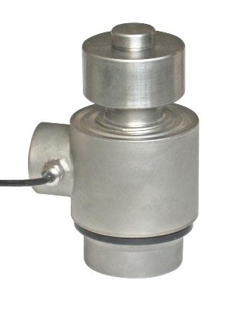
Capacity from 500 kg to 5000 kg
AISI4340NICKELPLATEDSTEEL
COMBINEDERROR±0.02%(0.017%C4;0.014%C5)
IP67PROTECTIONRATING
MOUNTINGKITS
CERTIFICATIONS
OIMLR60C3
ComplieswiththeEurasianCustomsUnionregulations
EquivalentoftheCEmarkingfortheUnitedKingdom
ComplieswithUnitedKingdomregulationsforlegalfortradeuse
CERTIFICATIONS ON REQUEST
Calibrationreport
LATAccrediacalibrationcertificateISO376orASTME74forcapacitiesfrom1000kgto10000kg
ATEXII1G2D (zone 0-1-2-21-22) (-)
IECEx (zone 0-1-2-20-21-22)
OIMLR60C4/C5
ComplieswiththeEurasianCustomsUnionregulationsforuseinpotentiallyexplosiveatmospheres
FMHazLoc-ComplieswiththeUnitedStatesandCanadaregulationsforuseinpotentiallyexplosiveatmospheres
ComplieswithChinesemarketregulationsforuseinpotentiallyexplosiveatmospheres
NTEP-ComplieswithUnitedStatesregulationsforlegalfortradeuse
DESCRIPTION
DIMENSIONS (mm)
TECHNICAL FEATURES
Specialsteelblock forcapacitiesupto2000kg. CODE
M12M18 6.88.86.88.8 50Nm79Nm205Nm280Nm
Fortheloadcellfixingscrews,providethetighteningtorqueindicatedinthetable Screw Screwclass Tighteningtorque
MaterialAISI4340nickelplatedsteel
OIMLR60Accuracyclass•Verificationintervals Nominalload(Emax)
Minimumverificationinterval(Vmin)
Combinederror
Protectionrating
RatedoutputInputresistance
C3•3000C4•4000C5•5000 500-1000-1500kg 2000-3000-5000kg 500-1000kg 1500-2000kg3000-5000kg Emax/10000Emax/15000Emax/20000Emax/18000 ±0.02%±0.017%±0.014% IP67 3mV/V±0.1%350±3.5
TemperatureeffectonzeroOutputresistance
TemperatureeffectonspanZerobalance
CompensatedtemperaturerangeInsulationresistance
OperatingtemperaturerangeSafeoverload(%offullscale)
Creepatnominalloadin30minutesUltimateoverload(%offullscale)
MaxsupplyvoltagewithoutdamageDeflectionatnominalload ELECTRICAL CONNECTIONS
4m(500-2000kg);6m(3000-5000kg) 5mm 4x0.22mm2
CablelengthSHIELD
Cablediameter+SIGNALGREEN Cores+EXCITATIONRED -SIGNALWHITE -EXCITATIONBLACK
Capacity from 500 kg to 5000 kg
17-4PHSTAINLESSSTEEL COMBINEDERROR±0.02% IP67PROTECTIONRATING
CERTIFICATIONS
ComplieswiththeEurasianCustomsUnionregulations
EquivalentoftheCEmarkingfortheUnitedKingdom
ComplieswithUnitedKingdomregulationsforlegalfortradeuse
CERTIFICATIONS ON REQUEST
Calibrationreport
MOUNTINGKITS
TFPS2000series
TF500/2000series
LATAccrediacalibrationcertificateISO376orASTME74forcapacitiesfrom1000kgto10000kg
ATEXII1G2D (zone 0-1-2-21-22) (-)

IECEx (zone 0-1-2-20-21-22)
ComplieswiththeEurasianCustomsUnionregulationsforuseinpotentiallyexplosiveatmospheres
FMHazLoc-ComplieswiththeUnitedStatesandCanadaregulationsforuseinpotentiallyexplosiveatmospheres
ComplieswithChinesemarketregulationsforuseinpotentiallyexplosiveatmospheres
DIMENSIONS (mm)
Fortheloadcellfixingscrews,providethetighteningtorqueindicatedinthetable
Screw
Screwclass
Tighteningtorque
TECHNICAL FEATURES
Material17-4PHstainlesssteel
OIMLR60Accuracyclass•Verificationintervals
Nominalload(Emax)
Minimumverificationinterval(Vmin)
Combinederror
Protectionrating
C3•3000 500-1000-2000kg5000kg Emax/7500Emax/9000
RatedoutputInputresistance
TemperatureeffectonzeroOutputresistance
TemperatureeffectonspanZerobalance
CompensatedtemperaturerangeInsulationresistance
OperatingtemperaturerangeSafeoverload(%offullscale)
Creepatnominalloadin30minutesUltimateoverload(%offullscale)
MaxsupplyvoltagewithoutdamageDeflectionatnominalload
ELECTRICAL CONNECTIONS
CablelengthSHIELD
Cablediameter+SIGNALGREEN
Cores+EXCITATIONRED -SIGNALWHITE -EXCITATIONBLACK
Capacity from 500 kg to 10000 kg
17-4PHSTAINLESSSTEEL COMBINEDERROR±0.02%(0.017%C4) IP68PROTECTIONRATING CAPACITY
CERTIFICATIONS
OIMLR60C3
ComplieswiththeEurasianCustomsUnionregulations
EquivalentoftheCEmarkingfortheUnitedKingdom
ComplieswithUnitedKingdomregulationsforlegalfortradeuse
CERTIFICATIONS ON REQUEST
Calibrationreport
LATAccrediacalibrationcertificateISO376orASTME74forcapacitiesfrom1000kgto10000kg
ATEXII1G2D (zone 0-1-2-21-22) (-)
IECEx (zone 0-1-2-20-21-22)
OIMLR60C4
ComplieswiththeEurasianCustomsUnionregulationsforuseinpotentiallyexplosiveatmospheres
ComplieswithChinesemarketregulationsforuseinpotentiallyexplosiveatmospheres
DIMENSIONS (mm)
Fortheloadcellfixingscrews,providethetighteningtorqueindicatedinthetable
Screw Screwclass Tighteningtorque
TECHNICAL FEATURES
Material17-4PHstainlesssteel
OIMLR60Accuracyclass•Verificationintervals
Nominalload(Emax)
Minimumverificationinterval(Vmin)
Combinederror
Protectionrating
RatedoutputInputresistance
TemperatureeffectonzeroOutputresistance
TemperatureeffectonspanZerobalance
CompensatedtemperaturerangeInsulationresistance
OperatingtemperaturerangeSafeoverload(%offullscale)
Creepatnominalloadin30minutesUltimateoverload(%offullscale)
MaxsupplyvoltagewithoutdamageDeflectionatnominalload
Calibratedcurrentoutput
ELECTRICAL CONNECTIONS
5m(500-7500kg);10m(10000kg) 5mm 4x0.20mm2 M12M20M24 6.88.86.88.86.88.8 50Nm795Nm290Nm400Nm500Nm690Nm
C3•3000C4•4000 500-1000-2000 5000-7500-10000kg500-1000-2000kg Emax/10000Emax/15000 ±0.02%±0.017% IP68 2mV/V±0.2%350±3.5 0.0018%°C350±3.5 0.0014%°C<±1% -10°C/+40°C5000M -35°C/+65°C150% 0.02%300% 18V0.4mm
ManufacturedaccordingtoOIMLR60standards
Capacity from 5000 kg to 10000 kg
SPECIALSTEEL COMBINEDERROR±0.1% IP68PROTECTIONRATING
CERTIFICATIONS
ComplieswiththeEurasianCustomsUnionregulations
EquivalentoftheCEmarkingfortheUnitedKingdom
CERTIFICATIONS ON REQUEST
Calibrationreport
LATAccrediacalibrationcertificateISO376orASTME74forcapacitiesfrom1000kgto10000kg
ATEXII1G2D (zone 0-1-2-21-22) (-)
IECEx (zone 0-1-2-20-21-22)
ComplieswiththeEurasianCustomsUnionregulationsforuseinpotentiallyexplosiveatmospheres
ComplieswithChinesemarketregulationsforuseinpotentiallyexplosiveatmospheres
DIMENSIONS (mm)
TECHNICAL FEATURES
MaterialSpecialsteel
Nominalload(Emax)
Combinederror
Protectionrating
RatedoutputInputresistance
TemperatureeffectonzeroOutputresistance
TemperatureeffectonspanZerobalance
CompensatedtemperaturerangeInsulationresistance
OperatingtemperaturerangeSafeoverload(%offullscale)
Creepatnominalloadin30minutesUltimateoverload(%offullscale)
MaxsupplyvoltagewithoutdamageDeflectionatnominalload
ELECTRICAL CONNECTIONS
17-4PHSTAINLESSSTEEL COMBINEDERROR±0.03% IP67-IP68PROTECTIONRATING TWOOUTPUTCABLESFORDUALSAFETYSYSTEMS
CERTIFICATIONS
ComplieswiththeEurasianCustomsUnionregulations
EquivalentoftheCEmarkingfortheUnitedKingdom
CERTIFICATIONS ON REQUEST
Calibrationreport
LATAccrediacalibrationcertificateISO376orASTME74forcapacitiesfrom1000kgto10000kg ATEXII3GD (zone 2-22) (-) capacity
DIMENSIONS (mm)
TECHNICAL FEATURES
Material17-4PHstainlesssteel
Nominalload(Emax)
Combinederror
Protectionrating
RatedoutputInputresistance
TemperatureeffectonzeroOutputresistance
TemperatureeffectonspanZerobalance
CompensatedtemperaturerangeInsulationresistance
OperatingtemperaturerangeSafeoverload(%offullscale)
Creepatnominalloadin30minutesUltimateoverload(%offullscale)
MaxsupplyvoltagewithoutdamageDeflectionatnominalload
1000-6000kg ±0.03% IP67(1000kg)-IP68(6000kg) 2mV/V±0.1%370±10 0.005%°C355±5 0.005%°C±2% -10°C/+50°C>5000M -20°C/+70°C150% 0.02%300% 15V0.25mm
ELECTRICAL CONNECTIONS
CablelengthSHIELD
Cablediameter+SIGNALGREEN
Cores+EXCITATION +REF./SENSE
The


AISI4340NICKELPLATEDSTEEL COMBINEDERROR±0.02% IP68PROTECTIONRATING MOUNTINGKIT
CERTIFICATIONS
ComplieswiththeEurasianCustomsUnionregulations
EquivalentoftheCEmarkingfortheUnitedKingdom
ComplieswithUnitedKingdomregulationsforlegalfortradeuse
CERTIFICATIONS ON REQUEST
Calibrationreport
ATEXII1G2D (zone 0-1-2-21-22) (-)
IECEx (zone 0-1-2-20-21-22)
ComplieswiththeEurasianCustomsUnionregulationsforuseinpotentiallyexplosiveatmospheres
FMHazLoc-ComplieswiththeUnitedStatesandCanadaregulationsforuseinpotentiallyexplosiveatmospheres
ComplieswithChinesemarketregulationsforuseinpotentiallyexplosiveatmospheres
COMPLEMENTARY ACCESSORIES
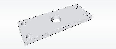
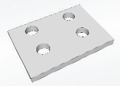
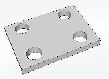
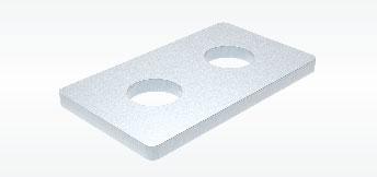
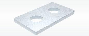
DESCRIPTIONCODE Galvanizedsteelplate.
DIMENSIONS (mm)
TECHNICAL FEATURES
MaterialAISI4340nickelplatedsteel
OIMLR60Accuracyclass•Verificationintervals
Nominalload(Emax)
Minimumverificationinterval(Vmin)
Combinederror
Protectionrating
RatedoutputInputresistance
TemperatureeffectonzeroOutputresistance
TemperatureeffectonspanZerobalance
CompensatedtemperaturerangeInsulationresistance
OperatingtemperaturerangeSafeoverload(%offullscale)
Creepatnominalloadin30minutesUltimateoverload(%offullscale) MaxsupplyvoltagewithoutdamageDeflectionatnominalload
ELECTRICAL CONNECTIONS

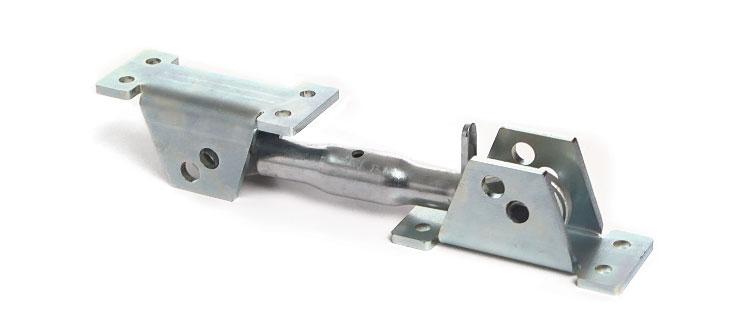
LEVELMEASUREMENTS
“Pointsupporthinge”canbeusedincombinationwiththeload cellsformeasuringthelevelofliquidorweighingpowderproducts thatdonotrequireahighdegreeofprecision.Itisabsolutely necessarythatthestructuretoweighthasauniformshapeandis geometricallydivisible.
Itmustbeperfectlylevelandthetypeofproducttobeweighed mustenablehorizontalpositioning,asifitwerealiquid(otherwise itloadingsystemswhichdistributetheproduct/loaduniformlyare required).Theelectronicweightdisplaywillshowtheeffective weightmultiplyingthesignalbytwoorthree,dependingonthe application.


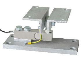
3SUPPORTSSTRUCTURES
1loadcell(A)+2hinges(B)
4SUPPORTSSTRUCTURES
2loadcelss(A)+2hinges(B) Hinges support


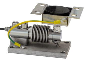
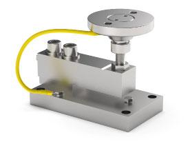
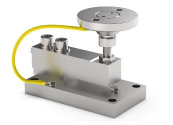
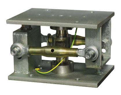
WEIGHINGSTRUCTURESNOTSUBJECTTOKNOCKSOR WINDEFFECT
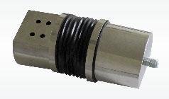
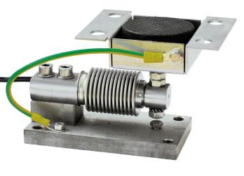
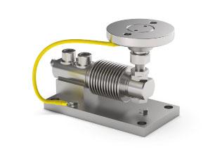
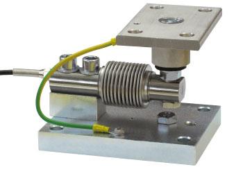
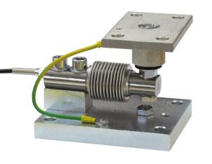
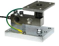
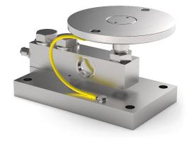
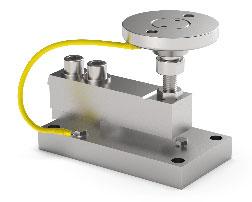
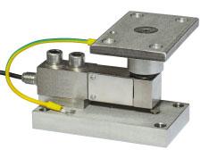
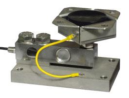
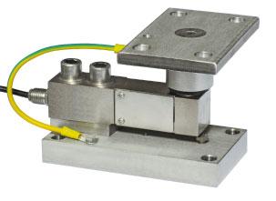
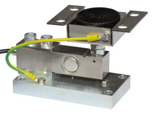
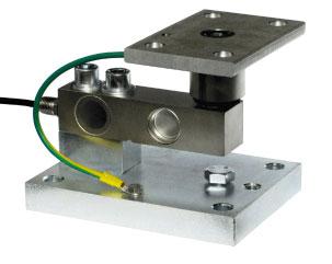
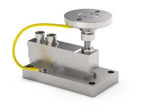
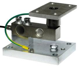
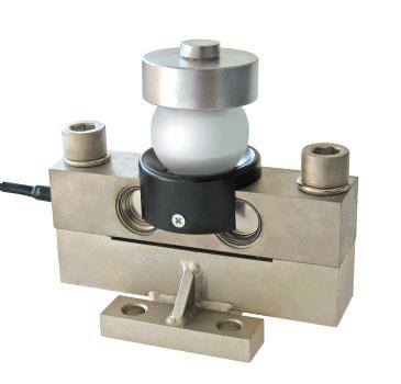
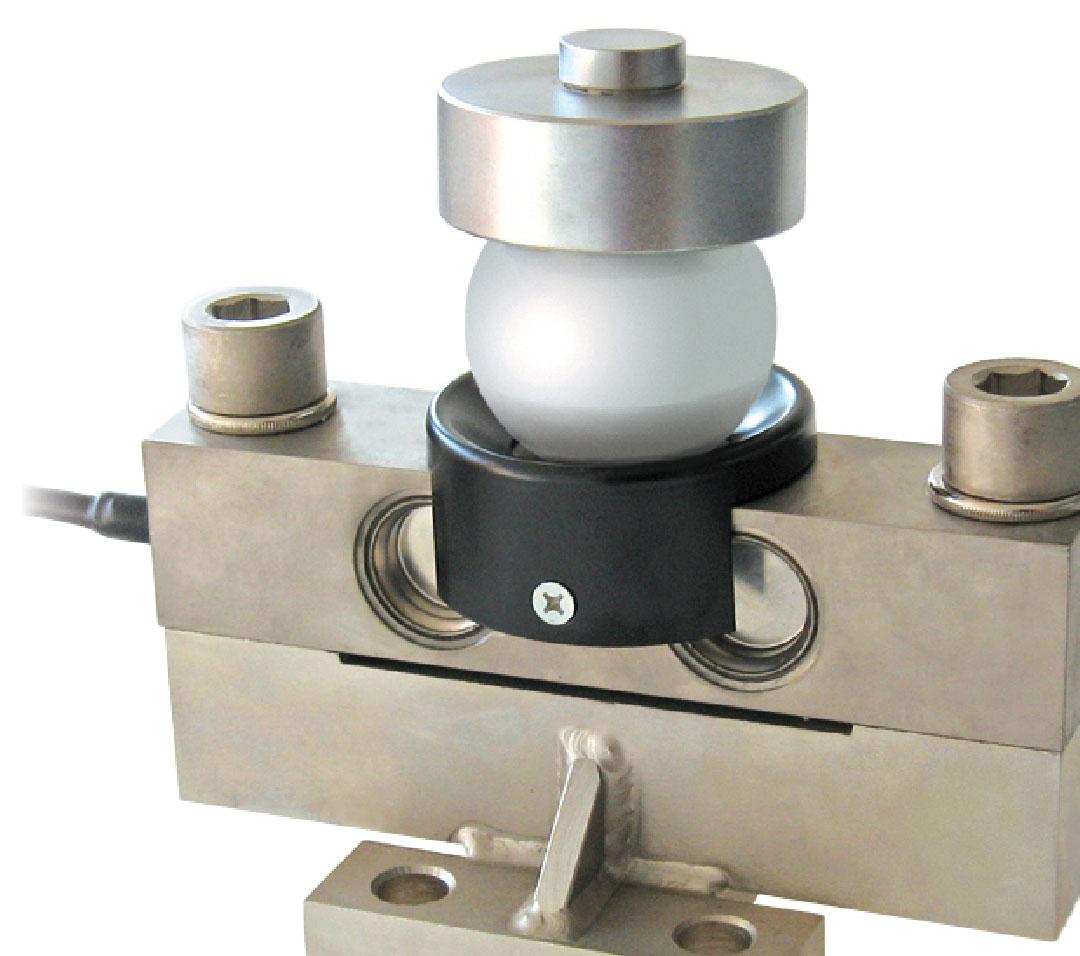
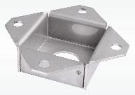
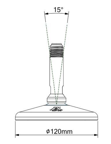
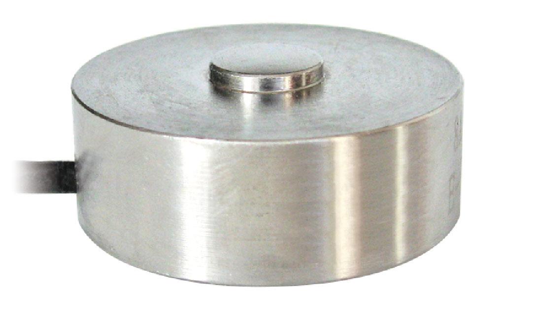
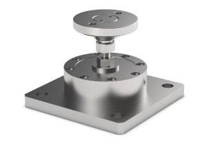
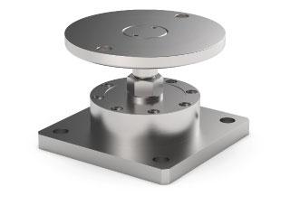
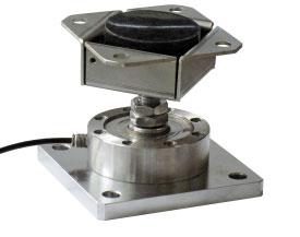
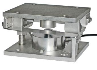
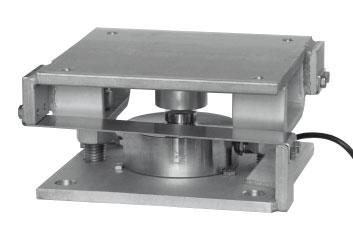
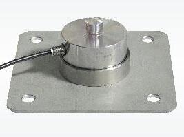
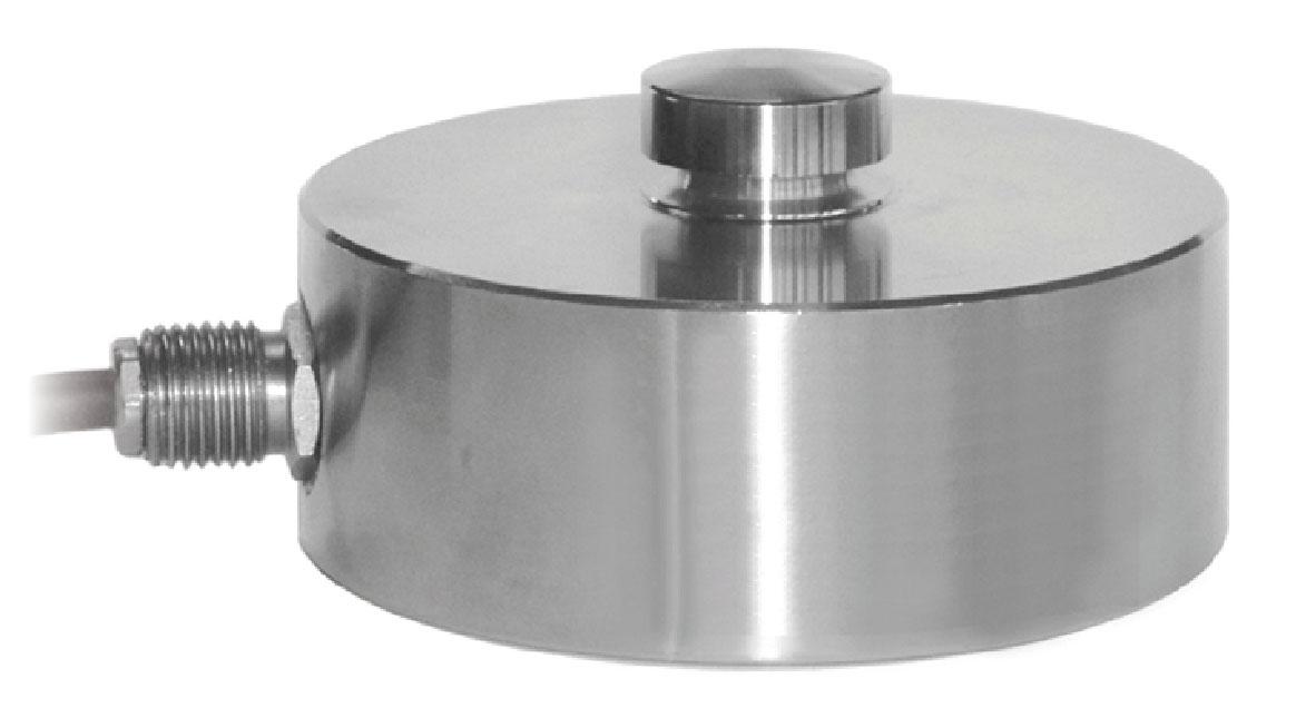
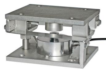
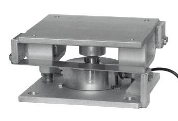
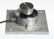
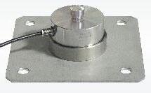
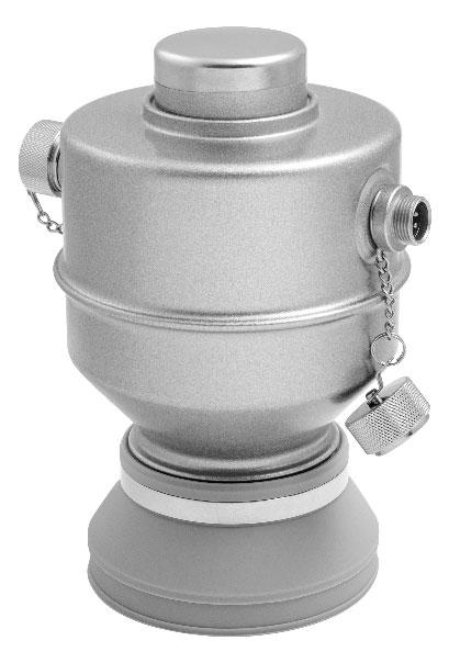
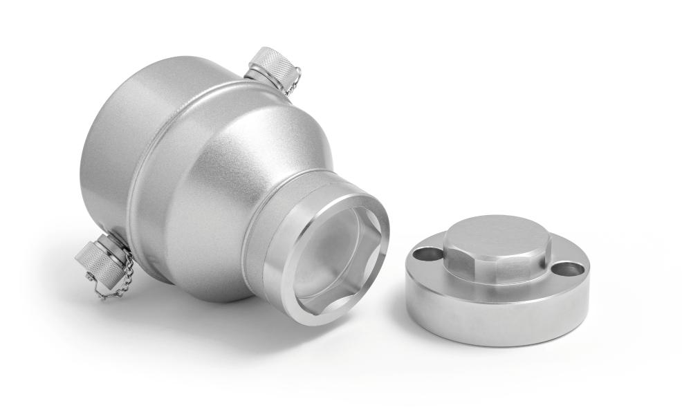
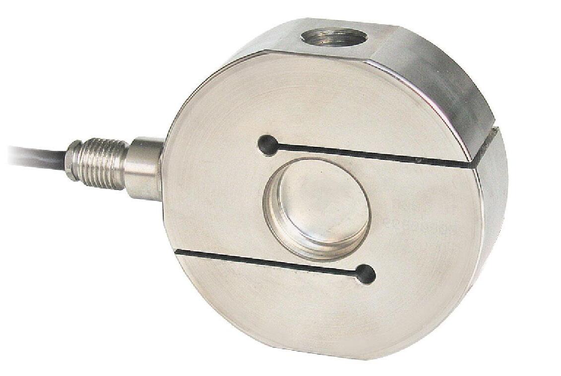
Theloadcell,equippedwithbasesplusball,isdesignedfor weighingstructuresnotsubjecttoknocksorwindeffect.
PIATTODTLisdesignedforfacilitatetheloadcellinstallationand removal;itwillbeenoughtolift1mmthestructure.Thedifferent bendingradiusbetweentheballandthebaseswhichcontainit, makesthatanysideshiftsleadtoonincreaseofthestructure.


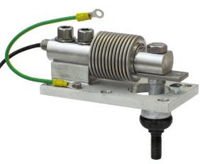
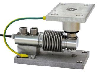
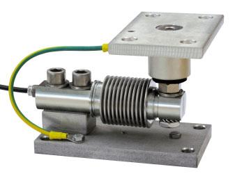
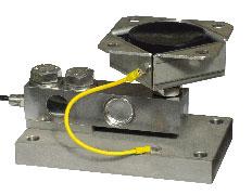
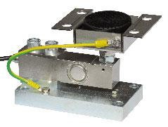
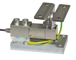
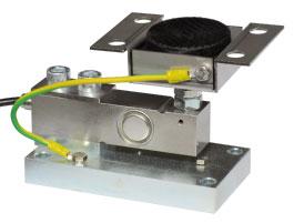
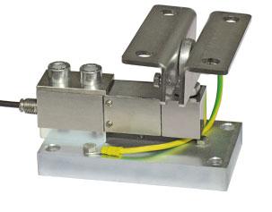
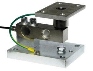
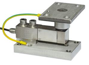
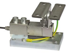
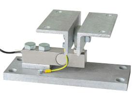
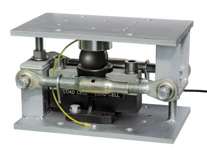
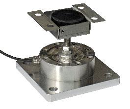
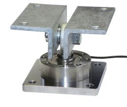
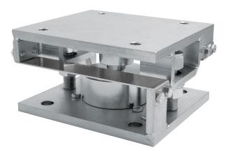
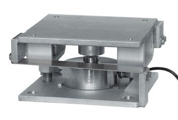
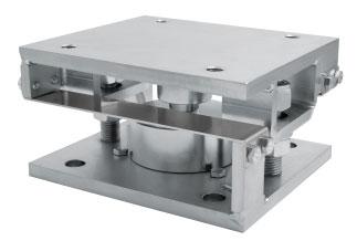
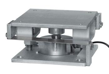
WEIGHINGSTRUCTURESSUBJECTTOKNOCKSORWIND EFFECT
TheVCOKDTLmountingkitisequippedwithtwostayrods againstlateralforceswithanultimatetensilestrengthof10000kg each,andtwothreadedrods(22mmdiameter)withnutstouse asajackfortheinsertionandextractionofthecellsandwith twoself-lockingnutsforanti-tiltfunction.Toensurethestability ofthestructure,thedesignermustconsiderfurthercontrivances accordingtothefollowingconditions:knocksandvibrations; windeffect;seismicconditions;hardnessofsupportstructure.
3SUPPORTSSTRUCTURES4SUPPORTSSTRUCTURES

Capacity from 20 klb to 60 klb
AISI4340NICKELPLATEDSTEEL COMBINEDERROR±0.02% IP68PROTECTIONRATING
MOUNTINGKIT
CERTIFICATIONS
ComplieswiththeEurasianCustomsUnionregulations
EquivalentoftheCEmarkingfortheUnitedKingdom
ComplieswithUnitedKingdomregulationsforlegalfortradeuse
CERTIFICATIONS ON REQUEST
Calibrationreport
LATAccrediacalibrationcertificateISO376orASTME74forcapacitiesfrom1000kgto10000kg
ATEXII1G2D (zone 0-1-2-21-22) (-)
IECEx (zone 0-1-2-20-21-22)
ComplieswiththeEurasianCustomsUnionregulationsforuseinpotentiallyexplosiveatmospheres
FMHazLoc-ComplieswiththeUnitedStatesandCanadaregulationsforuseinpotentiallyexplosiveatmospheres
ComplieswithChinesemarketregulationsforuseinpotentiallyexplosiveatmospheres
DIMENSIONS (mm)
TECHNICAL FEATURES
MaterialAISI4340nickelplatedsteel
OIMLR60Accuracyclass•Verificationintervals
Nominalload(Emax)
Minimumverificationinterval(Vmin)
Combinederror
Protectionrating
C3•3000 20,30,40,50,60klb Emax/10000-Emax/15000 ±0.023%
IP68
RatedoutputInputresistance
TemperatureeffectonzeroOutputresistance
TemperatureeffectonspanZerobalance
CompensatedtemperaturerangeInsulationresistance
OperatingtemperaturerangeSafeoverload(%offullscale)
Creepatnominalloadin30minutesUltimateoverload(%offullscale)
MaxsupplyvoltagewithoutdamageDeflectionatnominalload
ELECTRICAL CONNECTIONS
CablelengthSHIELD
Cablediameter+SIGNALGREEN Cores+EXCITATIONRED -SIGNALWHITE -EXCITATIONBLACK
2

17-4PHSTAINLESSSTEEL COMBINEDERROR±0.07% IP67PROTECTIONRATING ADJUSTABLEHEIGHT CAPACITY

CERTIFICATIONS
EquivalentoftheCEmarkingfortheUnitedKingdom
CERTIFICATIONS ON REQUEST Calibrationreport
ATEXII3GD (zone 2-22) (-)
COMPLEMENTARY ACCESSORIES

LATAccrediacalibrationcertificateISO376orASTME74forcapacitiesfrom1000kgto10000kg
DESCRIPTIONCODE
AISI304stainlesssteelplateforconstraintsagainstlateral forcesandanti-tilt. OnlyforSB2seriesfeet.
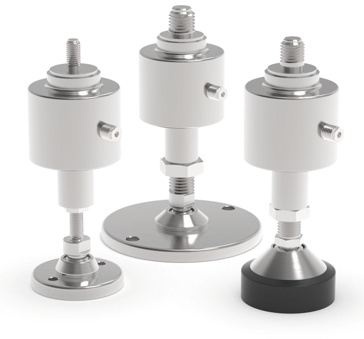
DIMENSIONS AND TECHNICAL SPECIFICATIONS
CAPACITY
75kgM12x1.75
150kgM12x1.75
300kgM12x1.75
500kgM12x1.75
1000kgM12x1.75
2000kgM12x1.75
5000kgM20x2.5
Installationnotes: screwthefootallthewayin; slightlyunscrewthefoottoadjust(maximumexcursion:10mm); tightenthefixingnut.
190÷200mm182÷192mm
10000kgM24x3-
ForfurtherinformationseetheSTRandSB2datasheets
TECHNICAL FEATURES
Material17-4PHstainlesssteel Nominalload
Combinederror Protectionrating
RatedoutputInputresistance
TemperatureeffectonzeroOutputresistance
TemperatureeffectonspanZerobalance
CompensatedtemperaturerangeInsulationresistance
OperatingtemperaturerangeSafeoverload(%offullscale)
Creepatnominalloadin30minutesUltimateoverload(%offullscale)
MaxsupplyvoltagewithoutdamageDeflectionatnominalload
ELECTRICAL CONNECTIONS
CablelengthSHIELD
Cablediameter+SIGNALGREEN
Cores+EXCITATION +REF./SENSE RED BLUE -SIGNALWHITE -EXCITATION -REF./SENSE BLACK YELLOW
The Company reserves the right to make changes to the technical data, drawings and images without notice.
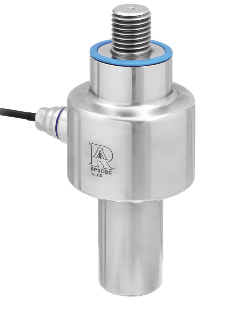
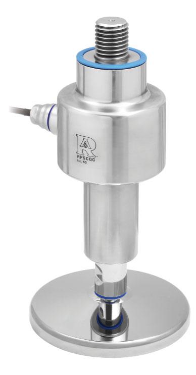
17-4PHSTAINLESSSTEEL COMBINEDERROR±0.1% IP69KPROTECTIONRATING CABLESUITABLEFORCONTACTWITHFOOD ADJUSTABLEHEIGHT HYGIENICDEVICERPSCQCAUTHORIZEDBY3-ASSI. CAPACITY
Foot not included.
CERTIFICATIONS
EquivalentoftheCEmarkingfortheUnitedKingdom
Americanstandardthatregulatesthedesign,productionanduseofhygienicequipment
CERTIFICATIONS ON REQUEST
Calibrationreport
LATAccrediacalibrationcertificateISO376orASTME74forcapacitiesfrom1000kgto10000kg
ATEXII3GD (zone 2-22) (-)
EXAMPLEOFINSTALLATIONON HYGIENICFOOT
DIMENSIONS AND TECHNICAL SPECIFICATIONS
CAPACITY
XL(mm)M(mm)H(FLC+HD)
1000kgM12x1.752440
2000kgM12x1.752440
5000kgM16x23040
5000kgM20x2.53540
10000kgM24x35040
10000kgM30x3.55050
20000kgM36x45050
TECHNICAL FEATURES
ANGULARADJUSTMENT
Installationnotes: screwthefootallthewayin; slightlyunscrewthefoottoadjust(maximumexcursion:10mm).
ForfurtherinformationseetheHDdatasheets Onrequest:hygienicfootwithdowelfastening
For other types of hygienic, non-hygienic feet or customizations feet customizations contact https://martinlevelling.it
Material17-4PHstainlesssteel Nominalload Combinederror
Protectionrating
RatedoutputInputresistance
TemperatureeffectonzeroOutputresistance
TemperatureeffectonspanZerobalance
CompensatedtemperaturerangeInsulationresistance
OperatingtemperaturerangeSafeoverload(%offullscale)
Creepatnominalloadin30minutesUltimateoverload(%offullscale)
MaxsupplyvoltagewithoutdamageDeflectionatnominalload
ELECTRICAL CONNECTIONS

ManufacturedaccordingtoOIMLR60standards
Capacity from 200 kg to 2500 kg
17-4PHSTAINLESSSTEEL COMBINEDERROR±0.5% IP67PROTECTIONRATING
CERTIFICATIONS
ComplieswiththeEurasianCustomsUnionregulations
EquivalentoftheCEmarkingfortheUnitedKingdom
CERTIFICATIONS ON REQUEST
Calibrationreport
LATAccrediacalibrationcertificateISO376orASTME74forcapacitiesfrom1000kgto10000kg
ATEXII1G2D (zone 0-1-2-21-22) (-)
IECEx (zone 0-1-2-20-21-22)
ComplieswiththeEurasianCustomsUnionregulationsforuseinpotentiallyexplosiveatmospheres
ComplieswithChinesemarketregulationsforuseinpotentiallyexplosiveatmospheres
TECHNICAL FEATURES
Material17-4PHstainlesssteel
Nominalload(Emax)
Combinederror
Protectionrating
RatedoutputInputresistance
TemperatureeffectonzeroOutputresistance
TemperatureeffectonspanZerobalance
CompensatedtemperaturerangeInsulationresistance
OperatingtemperaturerangeSafeoverload(%offullscale)
Creepatnominalloadin30minutesUltimateoverload(%offullscale)
MaxsupplyvoltagewithoutdamageDeflectionatnominalload
ELECTRICAL CONNECTIONS
ManufacturedaccordingtoOIMLR60standards
Capacity from 1000 kg to 5000 kg

MOUNTINGKITS
CERTIFICATIONS
ComplieswiththeEurasianCustomsUnionregulations
EquivalentoftheCEmarkingfortheUnitedKingdom
CERTIFICATIONS ON REQUEST
Calibrationreport
LATAccrediacalibrationcertificateISO376orASTME74forcapacitiesfrom1000kgto10000kg
ATEXII1G2D (zone 0-1-2-21-22) (-)
IECEx (zone 0-1-2-20-21-22)
ComplieswiththeEurasianCustomsUnionregulationsforuseinpotentiallyexplosiveatmospheres
ComplieswithChinesemarketregulationsforuseinpotentiallyexplosiveatmospheres
DIMENSIONS (mm)
TECHNICAL FEATURES
MaterialAISI420stainlesssteel
Nominalload(Emax)
Combinederror
Protectionrating
RatedoutputInputresistance
TemperatureeffectonzeroOutputresistance
TemperatureeffectonspanZerobalance
CompensatedtemperaturerangeInsulationresistance
OperatingtemperaturerangeSafeoverload(%offullscale)
Creepatnominalloadin30minutesUltimateoverload(%offullscale)
MaxsupplyvoltagewithoutdamageDeflectionatnominalload
ELECTRICAL CONNECTIONS
MOUNTINGKITS
V15000/V100000-EN1090series
Z15000/100000series
OIMLR60C2
ComplieswiththeEurasianCustomsUnionregulations
EquivalentoftheCEmarkingfortheUnitedKingdom
ComplieswithUnitedKingdomregulationsforlegalfortradeuse
CERTIFICATIONS ON REQUEST
Declarationofconformity+IP69Kmarkingprotectionrating
Water protection in case of high-pressure or steam jet cleaning (test: pressurized water is sprayed from a distance of max 150 mm)
Water pressure: 100 bar; temperature: 80 °C; test duration: 250 seconds (reference standard: DIN 40050-9)
Calibrationreport
LATAccrediacalibrationcertificateISO376orASTME74forcapacitiesfrom1000kgto10000kg
ATEXII1G2D (zone 0-1-2-21-22) (-)
IECEx (zone 0-1-2-20-21-22)
OIMLR60C3
ComplieswiththeEurasianCustomsUnionregulationsforuseinpotentiallyexplosiveatmospheres
ComplieswithChinesemarketregulationsforuseinpotentiallyexplosiveatmospheres
ComplieswiththeregulationsoftheRussianFederationforlegalfortradeuse
ComplieswithChinesemarketregulationsforlegalfortradeuse
TECHNICAL FEATURES
Material17-4PHstainlesssteel
OIMLR60Accuracyclass•Verificationintervals
Nominalload(Emax)
Minimumverificationinterval(Vmin)
Combinederror
Protectionrating
-C2•2000C3•3000
250-500-1000-15000kg 30000-50000-100000kg 2500-5000kg 7500-10000kg
2500-5000-7500kg 10000-12500kg
-Emax/15000Emax/15000 ±0.03%±0.03%±0.02% IP68
RatedoutputInputresistance
TemperatureeffectonzeroOutputresistance
TemperatureeffectonspanZerobalance
TemperaturerangeOIMLR60Insulationresistance
CompensatedtemperaturerangeSafeoverload(%offullscale)
OperatingtemperaturerangeUltimateoverload(%offullscale)
Creepatnominalloadin30minutesDeflectionatnominalload Maxsupplyvoltagewithoutdamage
ELECTRICAL CONNECTIONS
CablelengthSHIELD
Cablediameter+SIGNALGREEN
5m*(250-10000kg);10m(12500-100000kg) 5mm
6x0.14mm2
Cores+EXCITATION +REF./SENSE RED BLUE
*) On request: 10 m long cable version -SIGNALWHITE
TheOIMLR60C3approvedloadcellsareequippedwith10mlongcable-EXCITATION -REF./SENSE BLACK YELLOW
OPTIONS ON REQUEST
DESCRIPTION
10mlongcableversionfor250-10000kgcapacities
AISI420stainlesssteelloadcellversion(notOIMLapproved)
TworedundantstraingaugesWheatstonebridges(350)withtwooutputcables; fordualsafetysystems
COMPLEMENTARY ACCESSORIES
DESCRIPTION
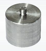
AISI304stainlesssteelthreadedupper baseforcompressionloadcells.
CODE
M12x1.75mmBASESUPFIL
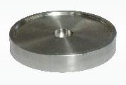
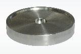
AISI304stainlesssteelturnedlowerbase forcompressionloadcells.
Ø110x22mm Ø140x23mm Ø180x23mm
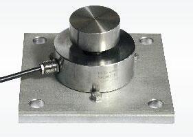
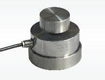
LowerplateandturnedupperbaseinAISI304stainlesssteel. Loadcellcapacity:upto12500kg.
BINF100 BINF126 BINF165
BASESUP P10000
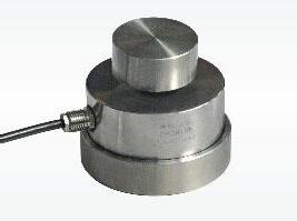
TurnedupperandlowerbasesinAISI304stainlesssteel. Loadcellcapacity:upto12500kg.
BASESUP BASEINF
LowerplateandturnedlowerbaseinAISI304stainlesssteel. Loadcellcapacity:upto12500kg.
BASEINF PIASTRA200
BOLTSTOFIX
Capacity from 1000 kg to 30000 kg
AISI420STAINLESSSTEEL COMBINEDERROR±0.05%
IP68PROTECTIONRATING
MOUNTINGKITS

V10000V15000-V30000-V100000Z10000Z15000/100000 -V10275
CERTIFICATIONS
ComplieswiththeEurasianCustomsUnionregulations
EquivalentoftheCEmarkingfortheUnitedKingdom
CERTIFICATIONS ON REQUEST
Declarationofconformity+IP69Kmarkingprotectionrating
Water protection in case of high-pressure or steam jet cleaning (test: pressurized water is sprayed from a distance of max 150 mm)
Water pressure: 100 bar; temperature: 80 °C; test duration: 250 seconds (reference standard: DIN 40050-9)
Calibrationreport
LATAccrediacalibrationcertificateISO376orASTME74forcapacitiesfrom1000kgto10000kg
ATEXII1G2D (zone 0-1-2-21-22) (-)
IECEx (zone 0-1-2-20-21-22)
ComplieswiththeEurasianCustomsUnionregulationsforuseinpotentiallyexplosiveatmospheres
ComplieswithChinesemarketregulationsforuseinpotentiallyexplosiveatmospheres
TECHNICAL FEATURES
MaterialAISI420stainlesssteel
Nominalload(Emax)
Combinederror
Protectionrating
RatedoutputInputresistance
TemperatureeffectonzeroOutputresistance
TemperatureeffectonspanZerobalance
CompensatedtemperaturerangeInsulationresistance
OperatingtemperaturerangeSafeoverload(%offullscale)
Creepatnominalloadin30minutesUltimateoverload(%offullscale)
MaxsupplyvoltagewithoutdamageDeflectionatnominalload
ELECTRICAL CONNECTIONS
COMPLEMENTARY ACCESSORIES
DESCRIPTION
AISI304stainlesssteelthreadedupper baseforcompressionloadcells.
AISI304stainlesssteelturnedlowerbase forcompressionloadcells.
LowerplateandturnedupperbaseinAISI304stainlesssteel. Loadcellcapacity:upto15000kg.
CODE
-SIGNALWHITE -EXCITATION -REF./SENSE BLACK YELLOW
TurnedupperandlowerbasesinAISI304stainlesssteel. Loadcellcapacity:upto15000kg.
LowerplateandturnedlowerbaseinAISI304stainlesssteel. Loadcellcapacity:upto15000kg.
BOLTSTOFIX THELOADCELL
ManufacturedaccordingtoOIMLR60standards
Capacity from 15000 kg to 50000 kg
MOUNTINGKITS
CERTIFICATIONS
ComplieswiththeEurasianCustomsUnionregulations
EquivalentoftheCEmarkingfortheUnitedKingdom
CERTIFICATIONS ON REQUEST
Calibrationreport
ATEXII1G2D (zone 0-1-2-21-22) (-)
IECEx (zone 0-1-2-20-21-22)
ComplieswiththeEurasianCustomsUnionregulationsforuseinpotentiallyexplosiveatmospheres
ComplieswithChinesemarketregulationsforuseinpotentiallyexplosiveatmospheres
OPTIONS ON REQUEST
DESCRIPTION
TworedundantstraingaugesWheatstonebridges(350) withtwooutputcables;fordualsafetysystems
V10000/V10275-EN1090series
V15000/V100000-EN1090series
Z15000/100000series
TECHNICAL FEATURES
Material17-4PHstainlesssteel
Nominalload(Emax)
Combinederror
Protectionrating
RatedoutputInputresistance
TemperatureeffectonzeroOutputresistance
TemperatureeffectonspanZerobalance
CompensatedtemperaturerangeInsulationresistance
OperatingtemperaturerangeSafeoverload(%offullscale)
Creepatnominalloadin30minutesUltimateoverload(%offullscale)
MaxsupplyvoltagewithoutdamageDeflectionatnominalload
ELECTRICAL CONNECTIONS
CablelengthSHIELD
Cablediameter+SIGNALGREEN Cores+EXCITATION +REF./SENSE RED BLUE -SIGNALWHITE -EXCITATION -REF./SENSE BLACK YELLOW
COMPLEMENTARY ACCESSORIES
DESCRIPTION
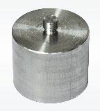

AISI304stainlesssteelthreadedupper baseforcompressionloadcells.
AISI304stainlesssteelturnedlowerbase forcompressionloadcells.
CODE
M12x1.75mmBASESUPFIL
Ø110x22mm Ø140x23mm BINF100 BINF126
LowerplateandturnedupperbaseinAISI304stainlesssteel. Loadcellcapacity:upto15000kg.
TurnedupperandlowerbasesinAISI304stainlesssteel. Loadcellcapacity:upto15000kg.
LowerplateandturnedlowerbaseinAISI304stainlesssteel. Loadcellcapacity:upto15000kg.
AISI304stainlesssteeladapterformountingkit: forØ82mmloadcells forØ100mmloadcells forØ126mmloadcells
BASESUP P10000
BASESUP BASEINF
BASEINF PIASTRA200
BOLTSTOFIX THELOADCELL
ManufacturedaccordingtoOIMLR60standards
Capacity from 200000 kg to 750000 kg
17-4PHSTAINLESSSTEEL COMBINEDERROR±0.10% IP68PROTECTIONRATING
CERTIFICATIONS
ComplieswiththeEurasianCustomsUnionregulations
EquivalentoftheCEmarkingfortheUnitedKingdom
CERTIFICATIONS ON REQUEST
Calibrationreport
ATEXII1G2D (zone 0-1-2-21-22) (-)
IECEx (zone 0-1-2-20-21-22)
ComplieswiththeEurasianCustomsUnionregulationsforuseinpotentiallyexplosiveatmospheres
ComplieswithChinesemarketregulationsforuseinpotentiallyexplosiveatmospheres
OPTIONS ON REQUEST
DESCRIPTION
TworedundantstraingaugesWheatstonebridges(350) withtwooutputcables;fordualsafetysystems
COMPLEMENTARY ACCESSORIES DESCRIPTION
Upperloading base.
Dimensions:Maximumstaticload:
DIMENSIONS (mm)
Material17-4PHstainlesssteel
Nominalload(Emax)
Combinederror
Protectionrating
RatedoutputInputresistance
TemperatureeffectonzeroOutputresistance
TemperatureeffectonspanZerobalance
CompensatedtemperaturerangeInsulationresistance
OperatingtemperaturerangeSafeoverload(%offullscale)
Creepatnominalloadin30minutesUltimateoverload(%offullscale)
MaxsupplyvoltagewithoutdamageDeflectionatnominalload

Capacity from 15000 kg to 50000 kg
AISI4340NICKELPLATEDSTEEL COMBINEDERROR±0.02% IP68PROTECTIONRATING KITCOKMOUNTINGACCESSORYINCLUDED MOUNTINGKIT

CERTIFICATIONS
ComplieswiththeEurasianCustomsUnionregulations
EquivalentoftheCEmarkingfortheUnitedKingdom
ComplieswithUnitedKingdomregulationsforlegalfortradeuse
CERTIFICATIONS ON REQUEST
Calibrationreport
ATEXII1G2D (zone 0-1-2-21-22) (-)
IECEx (zone 0-1-2-20-21-22)
ComplieswiththeEurasianCustomsUnionregulationsforuseinpotentiallyexplosiveatmospheres
ComplieswithChinesemarketregulationsforuseinpotentiallyexplosiveatmospheres
ComplieswiththeregulationsoftheRussianFederationforlegalfortradeuse
DESCRIPTIONCODE
DIMENSIONS
AISI5140nickelplatedsteelaccessorycomposedbyantirotationsystem,protectiverubberseal,2bases(upperand lower)and3self-centeringcylindricalplates.
TECHNICAL FEATURES
MaterialAISI4340nickelplatedsteel
OIMLR60Accuracyclass•Verificationintervals Nominalload(Emax)
Minimumverificationinterval(Vmin)
Combinederror
Protectionrating
C3•3000 15000-25000-50000kg
Emax/10000 ±0.02% IP68
RatedoutputInputresistance
TemperatureeffectonzeroOutputresistance
TemperatureeffectonspanZerobalance
CompensatedtemperaturerangeInsulationresistance
OperatingtemperaturerangeSafeoverload(%offullscale)
Creepatnominalloadin30minutesUltimateoverload(%offullscale)
MaxsupplyvoltagewithoutdamageDeflectionatnominalload
ELECTRICAL CONNECTIONS
CablelengthSHIELD Cablediameter+SIGNALGREEN Cores+EXCITATION +REF./SENSE
DESCRIPTION
AISI4340nickel-platedsteelbodyandAISI304stainlesssteelshell
Combinederror±0.014%
IP69Kprotectionrating
Two-connectordigitaloutput
CompatiblewithWINOXBGEandWTABBGE
Loadcellbaseswithanti-rotationmechanism
Earthingcable
Pipeclamps
Lightningandelectricalshockprotection
OIMLR60C5 IP69K
EquivalentoftheCEmarkingfortheUnitedKingdom
Declarationofconformity+IP69Kmarkingprotectionrating
Water protection in case of high-pressure or steam jet cleaning (test: pressurized water is sprayed from a distance of max 150 mm)
Water pressure: 100 bar; temperature: 80 °C; test duration: 250 seconds (reference standard: DIN 40050-9)
CERTIFICATIONS ON REQUEST
Calibrationreport
ComplieswithChinesemarketregulationsforlegalfortradeuse
OPTIONS ON REQUEST
DESCRIPTION
Anti-ratcableforconnectingtoindicator,length:20m, equippedwithconnectorononeendonly.
Anti-ratcable,length:10m, equippedwithconnectoronbothends.
Anti-ratcable,length:5m, equippedwithconnectoronbothends.
DIMENSIONS (mm)
MaterialAISI4340nickel-platedsteelbodyandAISI304stainlesssteelshell
OIML R60 Accuracy class • Verification intervals
Nominalload(Emax)
Minimumverificationinterval(Vmin)
Combinederror
Protectionrating
TemperatureeffectonzeroRecommendedpowersupplyvoltage
TemperatureeffectonspanSafeoverload(%offullscale)
CompensatedtemperaturerangeUltimateoverload(%offullscale)
OperatingtemperaturerangeRS485serialinterface
Creepatnominalloadin30minutesMaximumtransmissiondistance
Maxsupplyvoltagewithoutdamage
EXAMPLE OF APPLICATION
Capacity 25000 kg
17-4PHSTAINLESSSTEEL COMBINEDERROR±0.017% IP68PROTECTIONRATING LIGHTNINGPROTECTION
CERTIFICATIONS
OIMLR60C4
ComplieswiththeEurasianCustomsUnionregulations
EquivalentoftheCEmarkingfortheUnitedKingdom
ComplieswithUnitedKingdomregulationsforlegalfortradeuse
CERTIFICATIONS ON REQUEST
Calibrationreport
ATEXII1G2D (zone 0-1-2-21-22) (-)
IECEx (zone 0-1-2-20-21-22)
ComplieswiththeEurasianCustomsUnionregulationsforuseinpotentiallyexplosiveatmospheres
FMHazLoc-ComplieswiththeUnitedStatesandCanadaregulationsforuseinpotentiallyexplosiveatmospheres
ComplieswithChinesemarketregulationsforuseinpotentiallyexplosiveatmospheres
ComplieswiththeregulationsoftheRussianFederationforlegalfortradeuse
COMPLEMENTARY ACCESSORIES
DESCRIPTIONCODE
Stainlesssteelaccessorycomposedbyanti-rotationsystemwith O-ringand2bases(upperandlower).
Kitcomposedby2AISI5140nickelplatedsteelplates(upper andlower)forKITCObases.
(mm)
TECHNICAL FEATURES
Material17-4PHstainlesssteel
OIMLR60Accuracyclass•Verificationintervals
Nominalload(Emax)
Minimumverificationinterval(Vmin)
Combinederror
Protectionrating
C4•4000 25000kg Emax/15000 ±0.017% IP68
RatedoutputInputresistance
TemperatureeffectonzeroOutputresistance
TemperatureeffectonspanZerobalance
CompensatedtemperaturerangeInsulationresistance
OperatingtemperaturerangeSafeoverload(%offullscale)
Creepatnominalloadin30minutesUltimateoverload(%offullscale)
MaxsupplyvoltagewithoutdamageDeflectionatnominalload
ELECTRICAL CONNECTIONS
CablelengthSHIELD
Cablediameter+SIGNALGREEN
Cores+EXCITATIONRED -SIGNALWHITE -EXCITATIONBLACK
Capacity 30000 kg
17-4PHSTAINLESSSTEEL COMBINEDERROR±0.017% IP68PROTECTIONRATING
CERTIFICATIONS
OIMLR60C4
ComplieswiththeEurasianCustomsUnionregulations
EquivalentoftheCEmarkingfortheUnitedKingdom
ComplieswithUnitedKingdomregulationsforlegalfortradeuse
CERTIFICATIONS ON REQUEST
Calibrationreport
ATEXII1G2D (zone 0-1-2-21-22) (-)
IECEx (zone 0-1-2-20-21-22)
ComplieswiththeEurasianCustomsUnionregulationsforuseinpotentiallyexplosiveatmospheres
ComplieswithChinesemarketregulationsforuseinpotentiallyexplosiveatmospheres
ComplieswiththeregulationsoftheRussianFederationforlegalfortradeuse
COMPLEMENTARY ACCESSORIES
DESCRIPTIONCODE
HardenedAISI420stainlesssteelaccessorycomposedby anti-rotationsystem,protectiverubberseal,2bases(upperand lower)and3self-centeringcylindricalplates.
DIMENSIONS (mm)
TECHNICAL FEATURES
Material17-4PHstainlesssteel
OIMLR60Accuracyclass•Verificationintervals Nominalload(Emax)
Minimumverificationinterval(Vmin)
Combinederror
Protectionrating
RatedoutputInputresistance
C4•4000 30000kg Emax/10000 ±0.017% IP68 2mV/V±0.1%800±30
TemperatureeffectonzeroOutputresistance
TemperatureeffectonspanZerobalance
CompensatedtemperaturerangeInsulationresistance
OperatingtemperaturerangeSafeoverload(%offullscale)
Creepatnominalloadin30minutesUltimateoverload(%offullscale)
MaxsupplyvoltagewithoutdamageDeflectionatnominalload
Calibratedcurrentoutput
ELECTRICAL CONNECTIONS
CablelengthSHIELD
Cablediameter+SIGNALGREEN
Cores+EXCITATION +REF./SENSE


ManufacturedaccordingtoOIMLR60standards
Capacity from 50 kg to 500 kg
50-100kg:ALUMINUMALLOY(AVIONAL)
500kg:17-4PHSTAINLESSSTEEL COMBINEDERROR±0.05% IP65PROTECTIONRATING
COMPLEMENTARY ACCESSORIES
CERTIFICATIONS
ComplieswiththeEurasianCustomsUnionregulations
EquivalentoftheCEmarkingfortheUnitedKingdom
CERTIFICATIONS ON REQUEST
Calibrationreport
ATEXII3GD (zone 2-22) (-)
DIMENSIONS (mm)
TECHNICAL FEATURES
MaterialAluminumalloy(Avional)17-4PHstainlesssteel
Nominalload(Emax)
Combinederror
Protectionrating
RatedoutputInputresistance
TemperatureeffectonzeroOutputresistance
TemperatureeffectonspanZerobalance
CompensatedtemperaturerangeInsulationresistance
OperatingtemperaturerangeSafeoverload(%offullscale)
Creepatnominalloadin20minutesUltimateoverload(%offullscale)
MaxsupplyvoltagewithoutdamageDeflectionatnominalload
ELECTRICAL CONNECTIONS
CablelengthSHIELD
Cablediameter+SIGNALGREEN
Cores+EXCITATION
ManufacturedaccordingtoOIMLR60standards
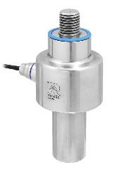
Capacity from 500 kg to 200000 kg
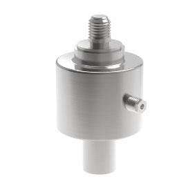
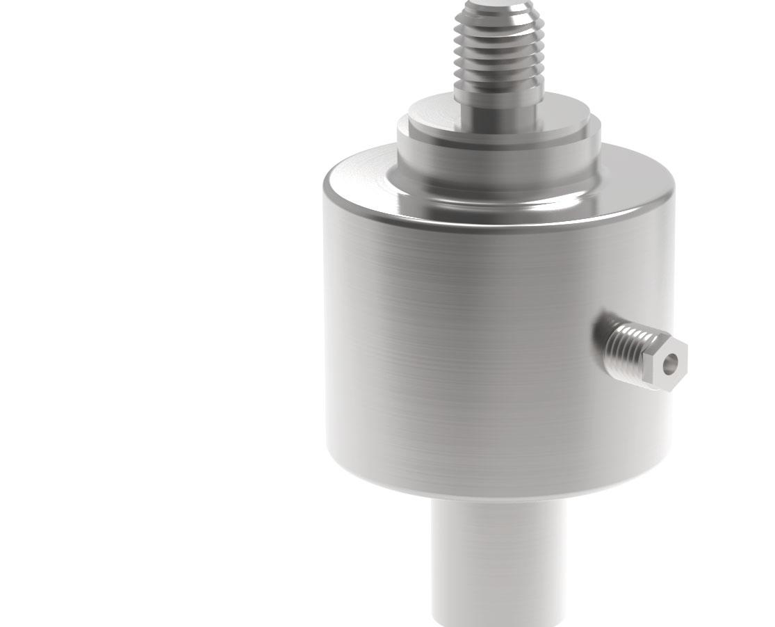
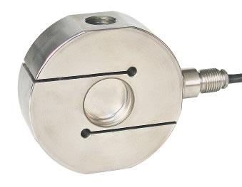
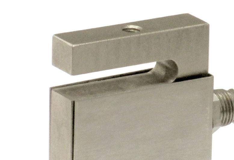
17-4PHSTAINLESSSTEEL BIDIRECTIONALTENSIONANDCOMPRESSION COMBINEDERROR±0.05%
PROTECTIONRATING:IP68(500-60000kg)-IP67(100000-200000kg)
CERTIFICATIONS
ComplieswiththeEurasianCustomsUnionregulations
EquivalentoftheCEmarkingfortheUnitedKingdom
CERTIFICATIONS ON REQUEST
Calibrationreport
LATAccrediacalibrationcertificateISO376orASTME74forcapacitiesfrom1000kgto10000kg
ATEXII1G2D (zone 0-1-2-21-22) (-)
IECEx (zone 0-1-2-20-21-22)
ComplieswiththeEurasianCustomsUnionregulationsforuseinpotentiallyexplosiveatmospheres
ComplieswithChinesemarketregulationsforuseinpotentiallyexplosiveatmospheres
OPTIONS ON REQUEST
DESCRIPTION
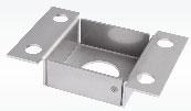
TworedundantstraingaugesWheatstonebridges(350)withtwooutputcables; fordualsafetysystems.
DIMENSIONS
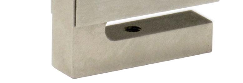
Fortheloadcellfixingscrews(•),providethetighteningtorqueindicatedinthetable Screw Screwclass Tighteningtorque forcapacitiesof10000,30000,60000,150000,200000kgusescrewsofclass8.8orhigher
M8M16M24
6.8A2-708.8A2-806.8A2-708.8A2-806.8A2-708.8A2-80 15Nm20Nm120Nm160Nm400Nm550Nm
TECHNICAL FEATURES
Material17-4PHstainlesssteel
Nominalload(Emax)
Combinederror
Protectionrating
500-1000-2000-5000-10000-20000-30000-60000-100000-150000-200000kg
RatedoutputInputresistance
TemperatureeffectonzeroOutputresistance
TemperatureeffectonspanZerobalance
CompensatedtemperaturerangeInsulationresistance
±0.05% IP68(500-60000kg),IP67(100000-200000kg) 2mV/V±0.3%700±20 0.005%°C700±5 0.005%°C±1% -20°C/+70°C>5000M
OperatingtemperaturerangeSafeoverload(%offullscale)
Creepatnominalloadin30minutesUltimateoverload(%offullscale)
MaxsupplyvoltagewithoutdamageDeflectionatnominalload
ELECTRICAL CONNECTIONS
ManufacturedaccordingtoOIMLR60standards
Capacity from 10000 kg to 20000 kg
SPECIALSTEEL BIDIRECTIONALTENSIONANDCOMPRESSION COMBINEDERROR±0.1% IP67PROTECTIONRATING
CAPACITY
CERTIFICATIONS
ComplieswiththeEurasianCustomsUnionregulations
EquivalentoftheCEmarkingfortheUnitedKingdom
CERTIFICATIONS ON REQUEST
Calibrationreport
LATAccrediacalibrationcertificateISO376orASTME74forcapacitiesfrom1000kgto10000kg
ATEXII1G2D (zone 0-1-2-21-22) (-)
IECEx (zone 0-1-2-20-21-22)
ComplieswiththeEurasianCustomsUnionregulationsforuseinpotentiallyexplosiveatmospheres
ComplieswithChinesemarketregulationsforuseinpotentiallyexplosiveatmospheres
TECHNICAL FEATURES
Nominalload(Emax)
Combinederror
Protectionrating
RatedoutputInputresistance
TemperatureeffectonzeroOutputresistance
TemperatureeffectonspanZerobalance
CompensatedtemperaturerangeInsulationresistance
OperatingtemperaturerangeSafeoverload(%offullscale)
Creepatnominalloadin30minutesUltimateoverload(%offullscale)
MaxsupplyvoltagewithoutdamageDeflectionatnominalload
ELECTRICAL CONNECTIONS

Capacity from 15 kg to 60 kg
AISI4140NICKELPLATEDSTEEL COMBINEDERROR±0.02% IP65PROTECTIONRATING

CERTIFICATIONS
ComplieswiththeEurasianCustomsUnionregulations
EquivalentoftheCEmarkingfortheUnitedKingdom
ComplieswithUnitedKingdomregulationsforlegalfortradeuse
CERTIFICATIONS ON REQUEST
Calibrationreport
ATEXII1G2D (zone 0-1-2-21-22) (-)
IECEx (zone 0-1-2-20-21-22)
ComplieswiththeEurasianCustomsUnionregulationsforuseinpotentiallyexplosiveatmospheres
ComplieswithChinesemarketregulationsforuseinpotentiallyexplosiveatmospheres
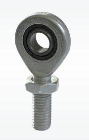
COMPLEMENTARY ACCESSORIES
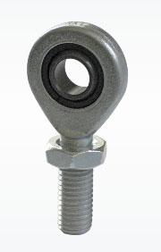
DESCRIPTION
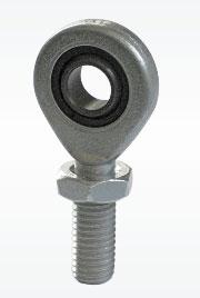
galvanizedC40 steelball-andsocketjointwithnut
Dimensions:Loadcellcapacity:
DIMENSIONS (mm)
MaterialAISI4140nickelplatedsteel
OIMLR60Accuracyclass•Verificationintervals
Nominalload(Emax)
Minimumverificationinterval(Vmin)
Combinederror
Protectionrating
RatedoutputInputresistance
TemperatureeffectonzeroOutputresistance
TemperatureeffectonspanZerobalance
CompensatedtemperaturerangeInsulationresistance
OperatingtemperaturerangeSafeoverload(%offullscale)
Creepatnominalloadin30minutesUltimateoverload(%offullscale)
MaxsupplyvoltagewithoutdamageDeflectionatnominalload
CablelengthSHIELD Cablediameter+SIGNALGREEN Cores+EXCITATIONRED -SIGNALWHITE -EXCITATIONBLACK
Capacity from 25 kg to 2500 kg
AISI4340NICKELPLATEDSTEEL COMBINEDERROR±0.02%(0.017%C4)
IP67PROTECTIONRATING
CERTIFICATIONS
OIMLR60C3
ComplieswiththeEurasianCustomsUnionregulations
EquivalentoftheCEmarkingfortheUnitedKingdom
ComplieswithUnitedKingdomregulationsforlegalfortradeuse
CERTIFICATIONS ON REQUEST
Calibrationreport
LATAccrediacalibrationcertificateISO376orASTME74forcapacitiesfrom1000kgto10000kg
ATEXII1G2D (zone 0-1-2-21-22) (-)
IECEx (zone 0-1-2-20-21-22)
OIMLR60C4
ComplieswiththeEurasianCustomsUnionregulationsforuseinpotentiallyexplosiveatmospheres
FMHazLoc-ComplieswiththeUnitedStatesandCanadaregulationsforuseinpotentiallyexplosiveatmospheres
ComplieswithChinesemarketregulationsforuseinpotentiallyexplosiveatmospheres
NTEP-ComplieswithUnitedStatesregulationsforlegalfortradeuse
COMPLEMENTARY ACCESSORIES
DIMENSIONS (mm)
DESCRIPTIONDIMENSIONSLOAD CELL CAPACITYCODE Ball-and-socketjointwithnut: stainlesssteel galvanizedC40steel
M12x1.75
M20x1.5 200-1000kg 2500kg EM-INOX
M8x1.25
M10x1.5
M12x1.75
M20x1.5 25kg 100kg 200-1000kg 2500kg EM
TECHNICAL FEATURES
MaterialAISI4340nickelplatedsteel
OIMLR60Accuracyclass•Verificationintervals
Nominalload(Emax)
Minimumverificationinterval(Vmin)
Combinederror
Protectionrating
-C3•3000C4•4000 25kg100-200-300kg 500-1000-2500kg 100-200-300kg 500-1000-2500kgEmax/10000 Emax/15000Emax/20000
±0.02%±0.02%±0.017%
IP67
RatedoutputInputresistance
TemperatureeffectonzeroOutputresistance
TemperatureeffectonspanZerobalance
CompensatedtemperaturerangeInsulationresistance
OperatingtemperaturerangeSafeoverload(%offullscale)
Creepatnominalloadin30minutesUltimateoverload(%offullscale)
MaxsupplyvoltagewithoutdamageDeflectionatnominalload
2mV/V±0.2%350±3.5 0.0015%°C350±3.5 0.0017%°C±1% -10°C/+40°C>5000M -35°C/+65°C150% 0.03%300% 18V0.4mm
ELECTRICAL CONNECTIONS
CablelengthSHIELD
5m(25-300kg);10m(500-2500kg) 5mm 4x0.24mm2
Cablediameter+SIGNALGREEN Cores+EXCITATIONRED -SIGNALWHITE -EXCITATIONBLACK
ManufacturedaccordingtoOIMLR60standards
Capacity from 50 kg to 300 kg
AISI420STAINLESSSTEEL COMBINEDERROR±0.03% IP67PROTECTIONRATING
CERTIFICATIONS
ComplieswiththeEurasianCustomsUnionregulations
EquivalentoftheCEmarkingfortheUnitedKingdom
CERTIFICATIONS ON REQUEST
Calibrationreport
LATAccrediacalibrationcertificateISO376orASTME74forcapacitiesfrom1000kgto10000kg
ATEXII1G2D (zone 0-1-2-21-22) (-)
IECEx (zone 0-1-2-20-21-22)
ComplieswiththeEurasianCustomsUnionregulationsforuseinpotentiallyexplosiveatmospheres
ComplieswithChinesemarketregulationsforuseinpotentiallyexplosiveatmospheres
COMPLEMENTARY ACCESSORIES
DESCRIPTIONDIMENSIONSLOAD CELL CAPACITYCODE Ball-and-socketjointwithnut:
DIMENSIONS (mm)
stainlesssteel
galvanizedC40steel
M12x1.75
M16x2
M20x1.5
M24x2
M12x1.75
M16x2
M20x1.5
M24x2
50-500kg 1000kg 2500kg 5000kg EM-INOX
50-500kg 1000kg 2500kg 5000kg EM
MaterialAISI420stainlesssteel
Nominalload(Emax)
Combinederror
Protectionrating
RatedoutputInputresistance
TemperatureeffectonzeroOutputresistance
TemperatureeffectonspanZerobalance
CompensatedtemperaturerangeInsulationresistance
OperatingtemperaturerangeSafeoverload(%offullscale)
Creepatnominalloadin30minutesUltimateoverload(%offullscale)
MaxsupplyvoltagewithoutdamageDeflectionatnominalload
Capacity from 100 kg to 12500 kg
17-4PHSTAINLESSSTEEL COMBINEDERROR±0.02% IP68PROTECTIONRATING
CERTIFICATIONS
OIMLR60C3
ComplieswiththeEurasianCustomsUnionregulations
EquivalentoftheCEmarkingfortheUnitedKingdom
ComplieswithUnitedKingdomregulationsforlegalfortradeuse
CERTIFICATIONS ON REQUEST
Declarationofconformity+IP69Kmarkingprotectionrating
Water protection in case of high-pressure or steam jet cleaning (test: pressurized water is sprayed from a distance of max 150 mm)
Water pressure: 100 bar; temperature: 80 °C; test duration: 250 seconds (reference standard: DIN 40050-9)
Calibrationreport
LATAccrediacalibrationcertificateISO376orASTME74forcapacitiesfrom1000kgto10000kg
ATEXII1G2D (zone 0-1-2-21-22) (-)
IECEx (zone 0-1-2-20-21-22)
ComplieswiththeEurasianCustomsUnionregulationsforuseinpotentiallyexplosiveatmospheres
ComplieswithChinesemarketregulationsforuseinpotentiallyexplosiveatmospheres
ComplieswiththeregulationsoftheRussianFederationforlegalfortradeuse
ComplieswithChinesemarketregulationsforlegalfortradeuse
DIMENSIONS (mm)
OPTIONS ON REQUEST
DESCRIPTION
TworedundantstraingaugesWheatstonebridges(350)withtwooutputcables; fordualsafetysystems.
COMPLEMENTARY ACCESSORIES
DESCRIPTIONDIMENSIONSLOAD CELL CAPACITYCODE Ball-and-socketjointwithnut:
M12x1.75
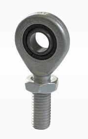
M16x2
M20x1.5
M24x2 100-300kg 500-1000kg 2500kg 5000-7500kg EM-INOX
M12x1.75
M16x2
M20x1.5
M24x2
M30x2
M36x3 100-300kg 500-1000kg 2500kg 5000-7500kg 10000kg 12500kg EM
TECHNICAL FEATURES
Material17-4PHstainlesssteel
OIMLR60Accuracyclass•Verificationintervals
Nominalload(Emax)
Minimumverificationinterval(Vmin)
Combinederror
Protectionrating
RatedoutputInputresistance
TemperatureeffectonzeroOutputresistance
TemperatureeffectonspanZerobalance
TemperaturerangeOIMLR60Insulationresistance
CompensatedtemperaturerangeSafeoverload(%offullscale)
OperatingtemperaturerangeUltimateoverload(%offullscale)
Creepatnominalloadin30minutesDeflectionatnominalload
Maxsupplyvoltagewithoutdamage
ELECTRICAL CONNECTIONS
CablelengthSHIELD Cablediameter+SIGNALGREEN
Cores+EXCITATION +REF./SENSE RED BLUE -SIGNALWHITE -EXCITATION -REF./SENSE BLACK YELLOW
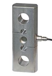
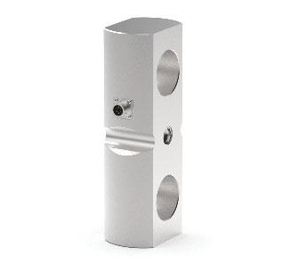
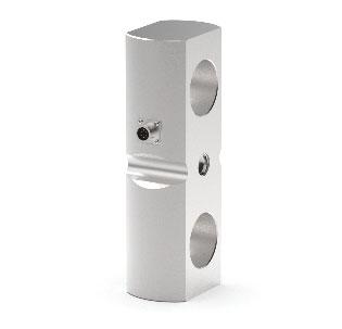
ManufacturedaccordingtoOIMLR60standards
Capacity from 5000 kg to 20000 kg
17-4PHSTAINLESSSTEEL HOLESFORSTANDARDSHACKLES COMBINEDERROR±0.03% IP68PROTECTIONRATING
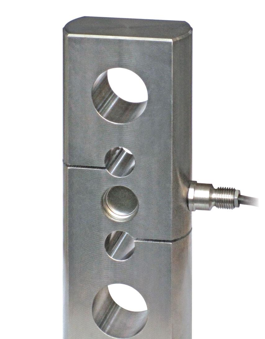

CERTIFICATIONS
ComplieswiththeEurasianCustomsUnionregulations
EquivalentoftheCEmarkingfortheUnitedKingdom
CERTIFICATIONS ON REQUEST
Calibrationreport
LATAccrediacalibrationcertificateISO376orASTME74forcapacitiesfrom1000kgto10000kg
ATEXII1G2D (zone 0-1-2-21-22) (-)
IECEx (zone 0-1-2-20-21-22)
ComplieswiththeEurasianCustomsUnionregulationsforuseinpotentiallyexplosiveatmospheres
ComplieswithChinesemarketregulationsforuseinpotentiallyexplosiveatmospheres
OPTIONS ON REQUEST
DESCRIPTION
TworedundantstraingaugesWheatstonebridges(350)withtwooutputcables;fordual safetysystems.
DIMENSIONS (mm)
TECHNICAL FEATURES
MaterialAISI420stainlesssteel
Nominalload(Emax)
Combinederror
Protectionrating
RatedoutputInputresistance
TemperatureeffectonzeroOutputresistance
TemperatureeffectonspanZerobalance
CompensatedtemperaturerangeInsulationresistance
OperatingtemperaturerangeSafeoverload(%offullscale)
Creepatnominalloadin30minutesUltimateoverload(%offullscale)
MaxsupplyvoltagewithoutdamageDeflectionatnominalload
ELECTRICAL CONNECTIONS
ManufacturedaccordingtoOIMLR60standards
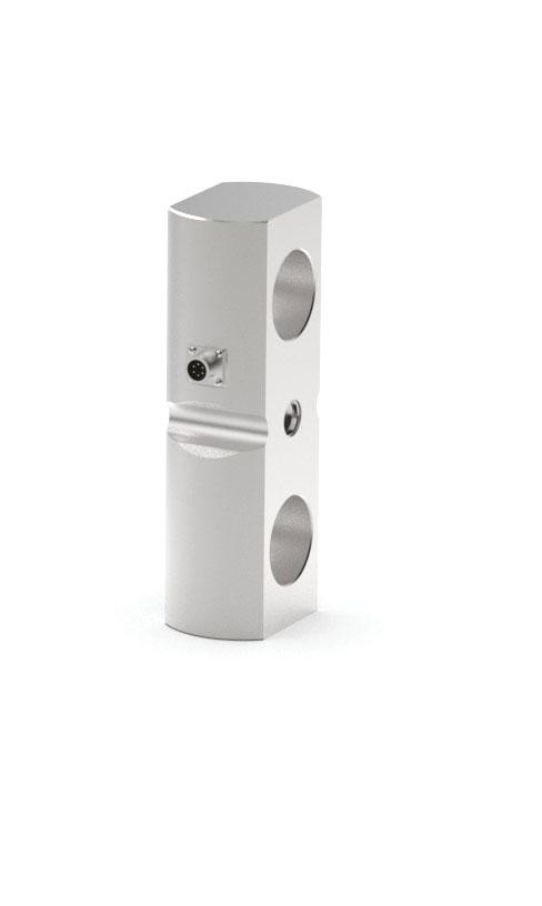
17-4PHSTAINLESSSTEEL HOLESFORSTANDARDSHACKLES COMBINEDERROR±0.08% IP67-IP68PROTECTIONRATING
CAPACITY
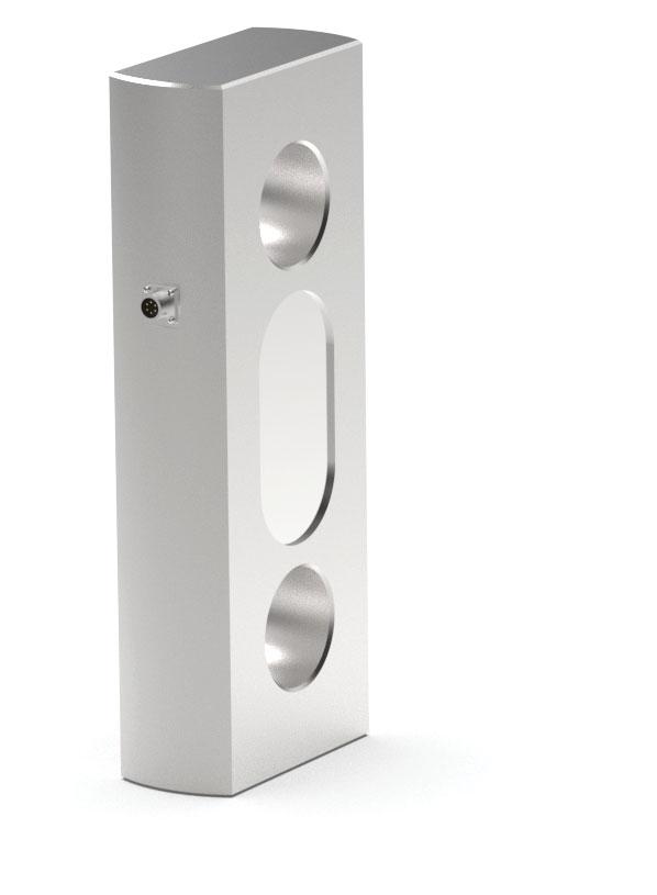
Capacity from 30000 kg to 100000 kgCapacity 250000 kg
WEIGHT (kg)
CERTIFICATIONS
ComplieswiththeEurasianCustomsUnionregulations
EquivalentoftheCEmarkingfortheUnitedKingdom
CERTIFICATIONS ON REQUEST
Calibrationreport
ATEXII1G2D (zone 0-1-2-21-22) (-)
IECEx (zone 0-1-2-20-21-22)
ComplieswiththeEurasianCustomsUnionregulationsforuseinpotentiallyexplosiveatmospheres
ComplieswithChinesemarketregulationsforuseinpotentiallyexplosiveatmospheres
OPTIONS ON REQUEST
DESCRIPTION
TworedundantstraingaugesWheatstonebridges(350)withtwooutputcables; fordualsafetysystems.
DIMENSIONS
TECHNICAL FEATURES
Material17-4PHstainlesssteel
Nominalload(Emax)
Combinederror
Protectionrating
30000-40000-50000-60000-100000-250000kg ±0.08%
RatedoutputInputresistance
IP68(30000-100000kg),IP67(250000kg) 1.0mV/V±0.1%350±20
TemperatureeffectonzeroOutputresistance
TemperatureeffectonspanZerobalance
CompensatedtemperaturerangeInsulationresistance
OperatingtemperaturerangeSafeoverload(%offullscale)
Creepatnominalloadin30minutesUltimateoverload(%offullscale)
MaxsupplyvoltagewithoutdamageDeflectionatnominalload
ELECTRICAL CONNECTIONS
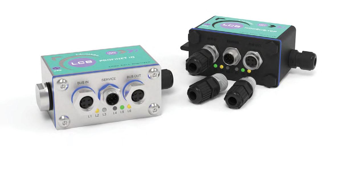
DESCRIPTION
LCBtransformsananalogloadcell(mV/Voutput)intoadigital one;itcanalsobeusedonexistingloadcellstodigitizethe weighingsystem.
ConceivedforIoTapplications(InternetofThings). PCconfigurationsoftwareviamicroUSBport. StatusLEDofthecommunicationinterface. Mounting:wiredorintegraltotheloadcellbodyviastandard ¼GASfitting(specificadaptersfordifferentthreadsaresupplied onrequest).
IP67boxinAISI304stainlesssteelorPA66nylonreinforcedwith glassfiber(dimensions:90x40x107mmincludingflyingconnectors). Suitableforwallmounting(supportsincluded:2fixingholes Ø6mm;centredistance:68mm).
3xIP67M12flyingconnectorsincludedinthesupply. Theinstrumentcanbeconfiguredandmanagedusingthefree “InstrumentManager”PCsoftware,whichyoucandownloadfrom www.laumas.com.
CERTIFICATIONS
ComplieswiththeEurasianCustomsUnionregulations
EquivalentoftheCEmarkingfortheUnitedKingdom
INPUTS/OUTPUTS AND COMMUNICATION
1microUSBport. 3relayoutputscontrolledbythesetpointvaluesorviaprotocols. 2digitalinputs:statusreadingviaserialcommunicationprotocols. 1loadcellinput.
SUPPORTS FORWALLMOUNTING
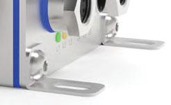
MICROUSBFOR PCCONFIGURATION
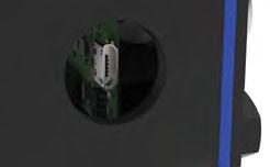
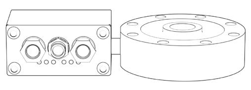
EXAMPLEOFAPPLICATIONWITHLOADCELL
ULRecognizedcomponent-ComplieswithUnitedStatesandCanadaregulations
FIELDBUSES


RS485
MaleM12circularconnector,A-coded,5-pin. FemaleM12circularconnector,A-coded,5-pin. Baudrate:2400,4800,9600,19200,38400,115200(bit/s).
RS485 + analog output.
MaleM12circularconnector,A-coded,5-pin.
FemaleM12circularconnector,A-coded,5-pin.
IO-Link.
2x maleM12circularconnector,A-coded,4-pin. Theinstrumentworksas device inaIO-Linknetwork.
CANopen.
MaleM12circularconnector,A-coded,5-pin.
FemaleM12circularconnector,A-coded,5-pin. Theinstrumentworksas slave inaCANopensynchronousnetwork.
CC-Link IE Field Basic.
2x femaleM12circularconnectors,D-coded,4-pin. Theinstrumentworksas slave inaCC-LinkIEFieldBasicnetwork.
CC-Link.
MaleM12circularconnector,A-coded,4-pin. FemaleM12circularconnector,A-coded,5-pin.
Theinstrumentworksas Remote Device Station inaCC-Linknetworkandoccupies3stations.
Profibus DP.
MaleM12circularconnector,B-coded,5-pin.
FemaleM12circularconnector,B-coded,5-pin. Theinstrumentworksas slave inaProfibusDPnetwork.
Modbus/TCP.
2x femaleM12circularconnectors,D-coded,4-pin. Theinstrumentworksas slave inaModbus/TCPnetwork.
Ethernet TCP/IP.
FemaleM12circularconnector,D-coded,4-pin.
TheinstrumentworksinanEthernetTCP/IPnetworkanditisaccessibleviawebbrowser.
Ethernet/IP.
2x femaleM12circularconnectors,D-coded,4-pin. Theinstrumentworksas adapter inanEthernet/IPnetwork.
Profinet IO.
2x femaleM12circularconnectors,D-coded,4-pin. Theinstrumentworksas device inaProfinetIOnetwork.
EtherCAT.
2x femaleM12circularconnectors,D-coded,4-pin. Theinstrumentworksas slave inanEtherCATnetwork.
POWERLINK.
2x femaleM12circularconnectors,D-coded,4-pin. Theinstrumentworksas slave inaPowerlinknetwork.
SERCOS III.
2x femaleM12circularconnectors,D-coded,4-pin. Theinstrumentworksas slave inaSercosIIInetwork.
coming soon coming soon coming soon coming soon
Connectionsto:
-PLCviaanalogoutputorfieldbuses; -PC/PLCviaRS485(upto99instrumentswithlinerepeaters,up to32withoutlinerepeaters); -upto4loadcellsinparallelbyjunctionbox.
TCP/IPWEBAPP:integratedsoftwareincombinationwiththe EthernetTCP/IPversionforremotesupervision,managementand controloftheinstrument.
Digitalfiltertoreducetheeffectsofweightoscillation.
Theoreticalcalibration(viaPCsoftware)andrealcalibration(with sampleweightsandthepossibilityofweightlinearizationupto8 points).
Calibrationviacharacterizationvaluesoftheloadcell. Tareweightzerosetting. Automaticzerosettingatpower-on. Grossweightzerotracking. Semi-automatictare(net/grossweight)andpresettare. Semi-automaticzero.
DirectconnectionbetweenRS485andRS232withoutconverter. ConfigurationbackupandrestoreviaPCsoftware.
Powersupplyandconsumption
BASE PROGRAM
Hysteresisandsetpointvaluesetting.
SINGLE PRODUCT LOADING PROGRAM
99settableformulas. Automaticfallcalculation. Toleranceerrorcontrol. Precisionbatchingthroughslowfunction. Precisionbatchingthroughtappingfunction. Consumptionstorage. Batchingstartviaexternalcontactorfieldbus.
12÷24VDC±10%;5W
A/DConverter24bit(16000000points)-4.8kHz
Divisions(withmeasurementrange±10mVandsensitivity2mV/V)
Measurementrange
Usableloadcellssensitivity
Conversionspersecond
±9999996.6nV/d
±26mV
±7mV/V
3filtertypes÷500
Relayoutputs3-max115VAC/150mA-24VDC/200mA
Digitalinputs
500 0÷ 2-5÷24VDC
MicroUSBportBtype-USB2.0(full-speed)
Humidity(condensatefree)
Storagetemperature
Workingtemperature
85%
-30°C+80°C
-20°C+50°C
Relayoutputs3-max30VAC,60VDC
Maxwallmountingheight
EquipmenttobepoweredbyPS2powersource
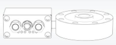
2m
DESCRIPTION
Loadcell+instrumentwiring.
The Company reserves the right to make changes to the technical data, drawings and images without notice.
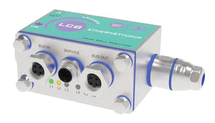
DESCRIPTION
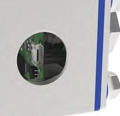
LCB3A transforms an analog load cell (mV/V output) into a digital one; it can also be used on existing load cells to digitize the weighing system.
Hygienic device RPSCQC authorized by 3-A SSI.
Conceived for IoT applications (Internet of Things).
PC configuration software via micro USB port.
Status LED of the communication interface.
Mounting: wired or integral to the load cell body via standard ¼ GAS fitting (specific adapters for different threads are supplied on request).
IP67 AISI 304 stainless steel box (dimensions: 90x40x107 mm including flying connectors).
3 M12 hygienic connectors with solder terminals included in the supply.
The instrument can be configured and managed using the free “Instrument Manager” PC software, which you can download from www.laumas.com.
INPUTS/OUTPUTS AND COMMUNICATION
1 micro USB port.
3 relay outputs controlled by the setpoint values or via protocols.
2 digital inputs: status reading via serial communication protocols.
1 load cell input.
CERTIFICATIONS
Complies with the Eurasian Custom Union regulations
Equivalent of the CE marking for the United Kingdom
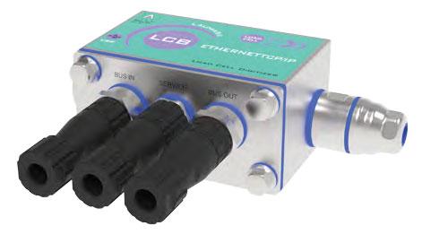
American standard that regulates the design, production and use of hygienic equipment
UL Recognized component - Complies with United States and Canada regulations
FIELDBUSES
RS485
Male M12 circular connector, A-coded, 5-pin.
Female M12 circular connector, A-coded, 5-pin.
Baud rate: 2400, 4800, 9600, 19200, 38400, 115200 (bit/s).
RS485 + analog output.
Male M12 circular connector, A-coded, 5-pin.
Female M12 circular connector, A-coded, 5-pin.
IO-Link.
2x male M12 circular connector, A-coded, 4-pin.
The instrument works as device in a IO-Link network.
CANopen.
Male M12 circular connector, A-coded, 5-pin.
Female M12 circular connector, A-coded, 5-pin.
The instrument works as slave in a CANopen synchronous network.
CC-Link IE Field Basic.
2x female M12 circular connectors, D-coded, 4-pin.
The instrument works as slave in a CC-Link IE Field Basic network.
CC-Link.
Male M12 circular connector, A-coded, 4-pin.
Female M12 circular connector, A-coded, 5-pin.
The instrument works as Remote Device Station in a CC-Link network and occupies 3 stations.
Profibus DP.
Male M12 circular connector, B-coded, 5-pin.
Female M12 circular connector, B-coded, 5-pin.
The instrument works as slave in a Profibus DP network.
Modbus/TCP.
2x female M12 circular connectors, D-coded, 4-pin.
The instrument works as slave in a Modbus/TCP network.
Ethernet TCP/IP.
Female M12 circular connector, D-coded, 4-pin.
The instrument works in an Ethernet TCP/IP network and it is accessible via web browser.
Ethernet/IP.
2x female M12 circular connectors, D-coded, 4-pin.
The instrument works as adapter in an Ethernet/IP network.
Profinet IO.
2x female M12 circular connectors, D-coded, 4-pin.
The instrument works as device in a Profinet IO network.
EtherCAT.
2x female M12 circular connectors, D-coded, 4-pin.
The instrument works as slave in an EtherCAT network.
POWERLINK.
2x female M12 circular connectors, D-coded, 4-pin.
The instrument works as slave in a Powerlink network.
SERCOS III.
2x female M12 circular connectors, D-coded, 4-pin.
The instrument works as slave in a Sercos III network.
coming soon
coming soon coming soon coming soon
Connections to:
- PLC via analog output or fieldbuses;
- PC/PLC via RS485 (up to 99 instruments with line repeaters, up to 32 without line repeaters);
- up to 4 load cells in parallel by junction box.
TCP/IP WEB APP: integrated software in combination with the Ethernet TCP/IP version for remote supervision, management and control of the instrument.
Digital filter to reduce the effects of weight oscillation.
Theoretical calibration (via PC software) and real calibration (with sample weights and the possibility of weight linearization up to 8 points).
Calibration via characterization values of the load cell.
Tare weight zero setting.
Automatic zero setting at power-on.
Gross weight zero tracking.
Semi-automatic tare (net/gross weight) and preset tare.
Semi-automatic zero.
Direct connection between RS485 and RS232 without converter.
Configuration backup and restore via PC software.
Power supply and consumption
BASE PROGRAM
Hysteresis and setpoint value setting.
SINGLE PRODUCT LOADING PROGRAM
99 settable formulas.
Automatic fall calculation.
Tolerance error control.
Precision batching through slow function.
Precision batching through tapping function.
Consumption storage.
Batching start via external contact or fieldbus.
12÷24 VDC ±10%; 5 W
A/D Converter24 bit (16000000 points) - 4.8 kHz
Divisions (with measurement range ±10 mV and sensitivity 2 mV/V)
Measurement range
Usable load cells sensitivity
Conversions per second
±999999 6.6 nV/d
±26 mV
±7 mV/V
3 filter types ÷500
Relay outputs3 - max 115 VAC/150 mA - 24 VDC/200 mA
Digital inputs
2 - 5÷24 VDC
Micro USB portB type - USB 2.0 (full-speed)
Humidity (condensate free)
Storage temperature
Working temperature
Relay outputs3 - max 30 VAC, 60 VDC
Max wall mounting height
Equipment to be powered by PS2 power source
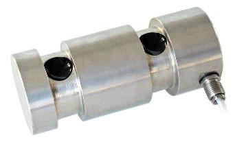

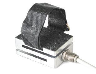
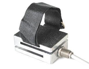
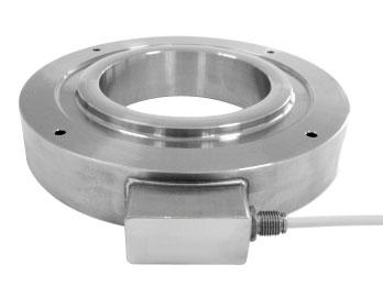
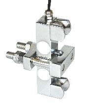
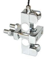
ManufacturedaccordingtoOIMLR60standards
Capacity from 5000 kg to 20000 kg
17-4PHSTAINLESSSTEEL COMBINEDERROR±0.1%
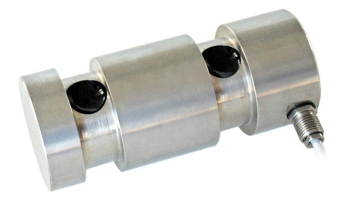
CERTIFICATIONS
ComplieswiththeEurasianCustomsUnionregulations
EquivalentoftheCEmarkingfortheUnitedKingdom
CERTIFICATIONS ON REQUEST
Calibrationreport
LATAccrediacalibrationcertificateISO376orASTME74forcapacitiesfrom1000kgto10000kg
ATEXII1G2D (zone 0-1-2-21-22) (-)
IECEx (zone 0-1-2-20-21-22)
ComplieswiththeEurasianCustomsUnionregulationsforuseinpotentiallyexplosiveatmospheres
ComplieswithChinesemarketregulationsforuseinpotentiallyexplosiveatmospheres
OPTIONS ON REQUEST
DESCRIPTION
TworedundantstraingaugesWheatstonebridges(350)withtwooutputcables;fordual safetysystems
TECHNICAL FEATURES
Material17-4PHstainlesssteel
Nominalload(Emax)
Combinederror
Protectionrating
RatedoutputInputresistance
TemperatureeffectonzeroOutputresistance
TemperatureeffectonspanZerobalance
CompensatedtemperaturerangeInsulationresistance
OperatingtemperaturerangeSafeoverload(%offullscale)
Creepatnominalloadin30minutesUltimateoverload(%offullscale)
MaxsupplyvoltagewithoutdamageDeflectionatnominalload
ELECTRICAL CONNECTIONS
ManufacturedaccordingtoOIMLR60standards
Capacity 100 kg
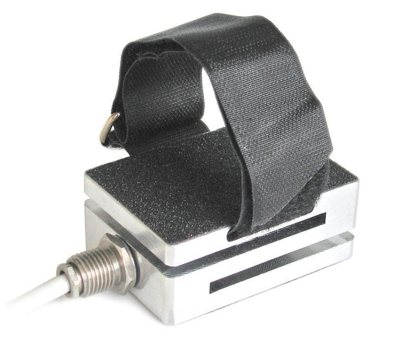
ALUMINUM COMBINEDERROR±0.08% IP65PROTECTIONRATING FLEXIBLECABLE
CAPACITY
CERTIFICATIONS
ComplieswiththeEurasianCustomsUnionregulations
EquivalentoftheCEmarkingfortheUnitedKingdom
CERTIFICATIONS ON REQUEST
Calibrationreport
OPTIONS ON REQUEST
DESCRIPTION
TworedundantstraingaugesWheatstonebridges(350)withtwooutputcables; fordualsafetysystems
TECHNICAL FEATURES
MaterialAluminum
Nominalload(Emax)
Combinederror
Protectionrating
RatedoutputInputresistance
TemperatureeffectonzeroOutputresistance
TemperatureeffectonspanZerobalance
CompensatedtemperaturerangeInsulationresistance
OperatingtemperaturerangeSafeoverload(%offullscale)
Creepatnominalloadin30minutesUltimateoverload(%offullscale)
MaxsupplyvoltagewithoutdamageDeflectionatnominalload
ELECTRICAL CONNECTIONS
Cablelength+SIGNALBROWN
ManufacturedaccordingtoOIMLR60standards
Capacity from 30000 kg to 250000 kg
CERTIFICATIONS
ComplieswiththeEurasianCustomsUnionregulations
EquivalentoftheCEmarkingfortheUnitedKingdom
CERTIFICATIONS ON REQUEST
Calibrationreport
ATEXII1G2D (zone 0-1-2-21-22) (-)
IECEx (zone 0-1-2-20-21-22)
ComplieswiththeEurasianCustomsUnionregulationsforuseinpotentiallyexplosiveatmospheres
ComplieswithChinesemarketregulationsforuseinpotentiallyexplosiveatmospheres

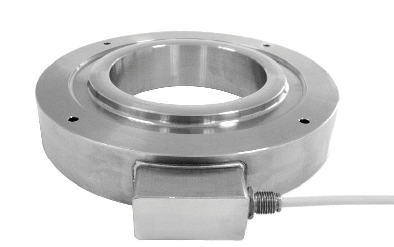
OPTIONS ON REQUEST
DESCRIPTION
TworedundantstraingaugesWheatstonebridges(350)withtwooutputcables; fordualsafetysystems.
COMPLEMENTARY ACCESSORIES
DESCRIPTIONCODE
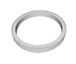
Galvanizedsteelplatesforloaddistribution.
TECHNICAL FEATURES - DIMENSIONS
Material17-4PHstainlesssteel
Nominalload(Emax)
Combinederror
Protectionrating
RatedoutputInputresistance
TemperatureeffectonzeroOutputresistance
TemperatureeffectonspanZerobalance
CompensatedtemperaturerangeInsulationresistance
OperatingtemperaturerangeSafeoverload(%offullscale)
Creepatnominalloadin30minutesUltimateoverload(%offullscale)
MaxsupplyvoltagewithoutdamageDeflectionatnominalload
ELECTRICAL CONNECTIONS
ManufacturedaccordingtoOIMLR60standards
Capacity from 2000 kg to 40000 kg
AISI4140NICKELPLATEDSTEEL LOADLIMITINGACCURACY±2%ONFULLSCALE IP67PROTECTIONRATING SUITABLEASLOADLIMITERFORLIFTINGEQUIPMENT RAPIDMOUNTING(alsoonpre-existingliftingsystems)

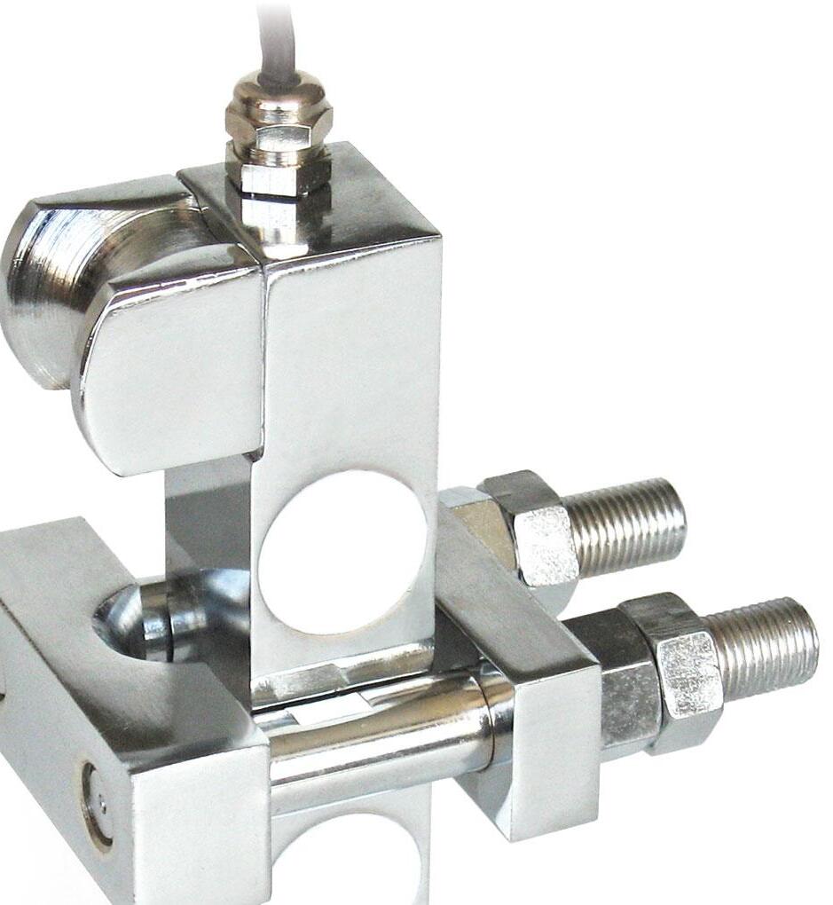
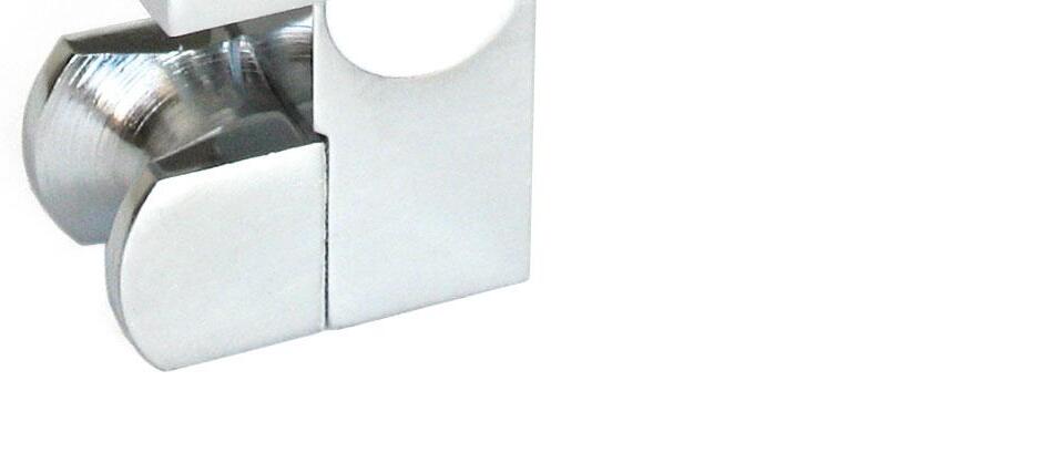
WIRE
up to up to up to up to up to
CERTIFICATIONS
ComplieswiththeEurasianCustomsUnionregulations EquivalentoftheCEmarkingfortheUnitedKingdom
CERTIFICATIONS ON REQUEST
ATEXII1G2D (zone 0-1-2-21-22) (-)
IECEx (zone 0-1-2-20-21-22)
ComplieswiththeEurasianCustomsUnionregulationsforuseinpotentiallyexplosiveatmospheres
ComplieswithChinesemarketregulationsforuseinpotentiallyexplosiveatmospheres
SCREW TIGHTENING TORQUES
Diameterofthesteelcable(mm)
Tighteningtorque(Nm)
TECHNICAL FEATURES
MaterialAISI4140nickelplatedsteel
Nominalload(Emax)
Loadlimitingaccuracyonfullscale
Protectionrating
RatedoutputInputresistance
TemperatureeffectonzeroOutputresistance
TemperatureeffectonspanZerobalance
CompensatedtemperaturerangeInsulationresistance
OperatingtemperaturerangeSafeoverload(%offullscale)
Creepatnominalloadin30minutesUltimateoverload(%offullscale)
MaxsupplyvoltagewithoutdamageDeflectionatnominalload
ELECTRICAL CONNECTIONS
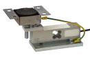
Series load cells:
Up to 300 kg application range
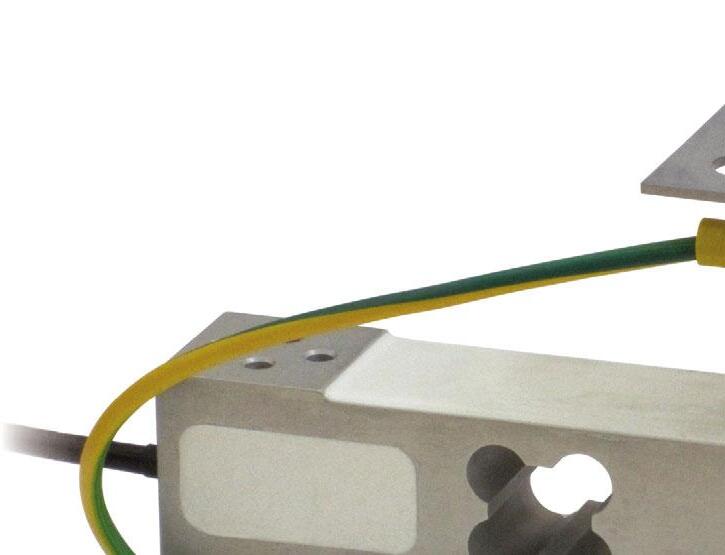
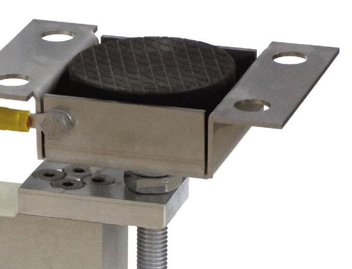
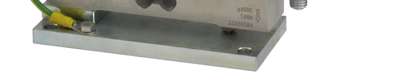
DESCRIPTION
Adjustable upper plate in galvanized steel (PPVZ).
Lower plate and block in galvanized steel.
Constraint against lateral forces and anti-tilt by galvanized steel self-centering joint foot.
Compensation for any misalignments of the support plates of the structure.
Adjustable height.
Locking screw to avoid damage during transport and installation. Can be used for systems with at least 3 supports.
During the transport and installation the lock (*) must touch under the load cell. After installation, move the lock away from the load cell. Interconnect the lower plates to the earthing. In case of structure with four-point support, if one-point does not touch the support base of the foot, you must proceed to adjust foot height. For the load cell fixing screws (•), provide a tightening torque of 7.5 Nm.
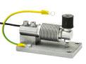
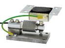
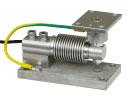
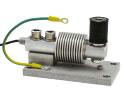

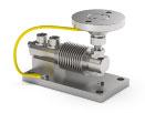
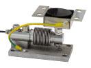
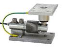
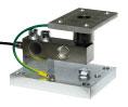
Series load cells:
Up to 300 kg application range
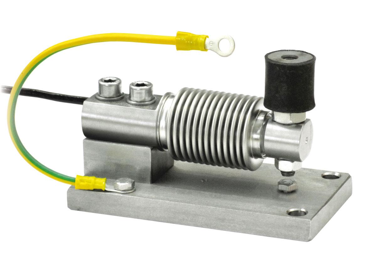
DESCRIPTION
Compression joint in AISI 304 stainless steel and rubber. Lower plate and block in AISI 304 stainless steel. Compensation for any misalignments of the support plates of the structure.
Locking screw to avoid damage during transport and installation. Can be used for systems with at least 3 supports.
During the transport and installation the lock (*) must touch under the load cell. After installation, move the lock away from the load cell.
Connect the structure to be weighed by means of copper wire, then connect all the lower plates to the earthing system.
In case of structure with four-point support, if one-point does not touch the upper part of the mounting kit, you must proceed to insert a shim before fixing the bolts.
For the load cell fixing screws (•), provide a tightening torque of 19 Nm.
Series load cells: MAX STATIC LOAD
Up to 300 kg application range
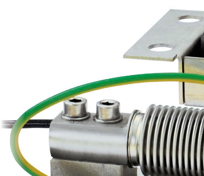
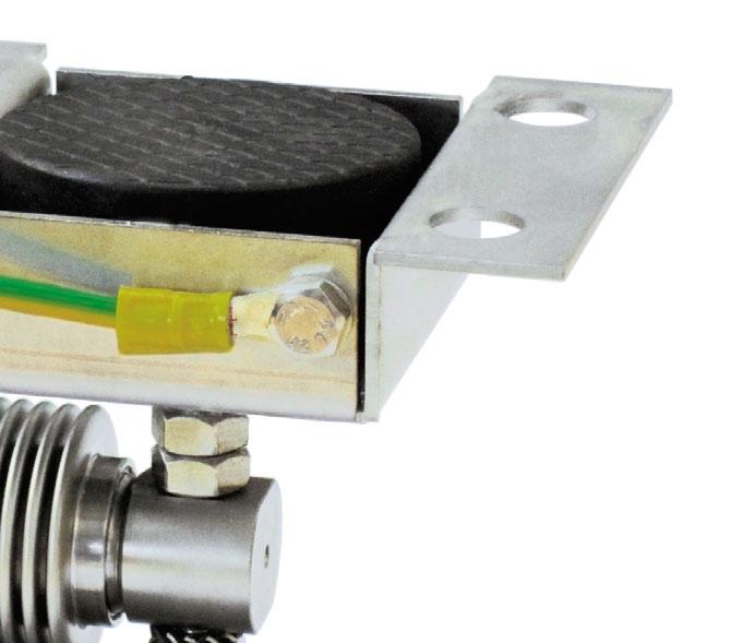
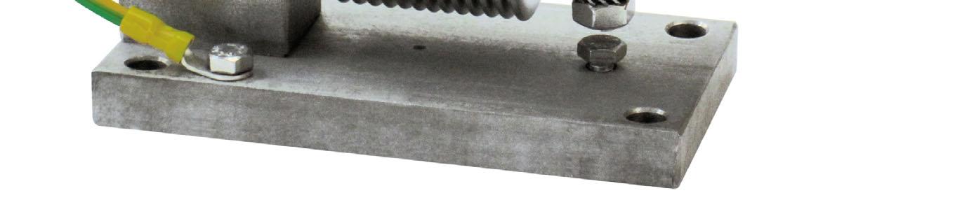
LOAD CELLS
DESCRIPTION
Adjustable upper plate in AISI 304 stainless steel (PPV) or galvanized steel (PPVZ).
Lower plate and block in AISI 304 stainless steel.
Constraint against lateral forces and anti-tilt by AISI 304 stainless steel (TFCPV, TFCPVZ, TFCPV10) or galvanized steel (TFCPVZ10) self-centering joint foot.
Compensation for any misalignments of the support plates of the structure.
Partial height adjustment.
Locking screw to avoid damage during transport and installation.
WEIGHT (kg)
During the transport and installation the lock (*) must touch under the load cell. After installation, move the lock away from the load cell.
Interconnect the lower plates to the earthing. In case of structure with four-point support, if one-point does not touch the upper part of the mounting kit, you must proceed to insert a shim before fixing the bolts. For the load cell fixing screws (•), provide a tightening torque of 19 Nm.
Series load cells:
Up to 300 kg application range
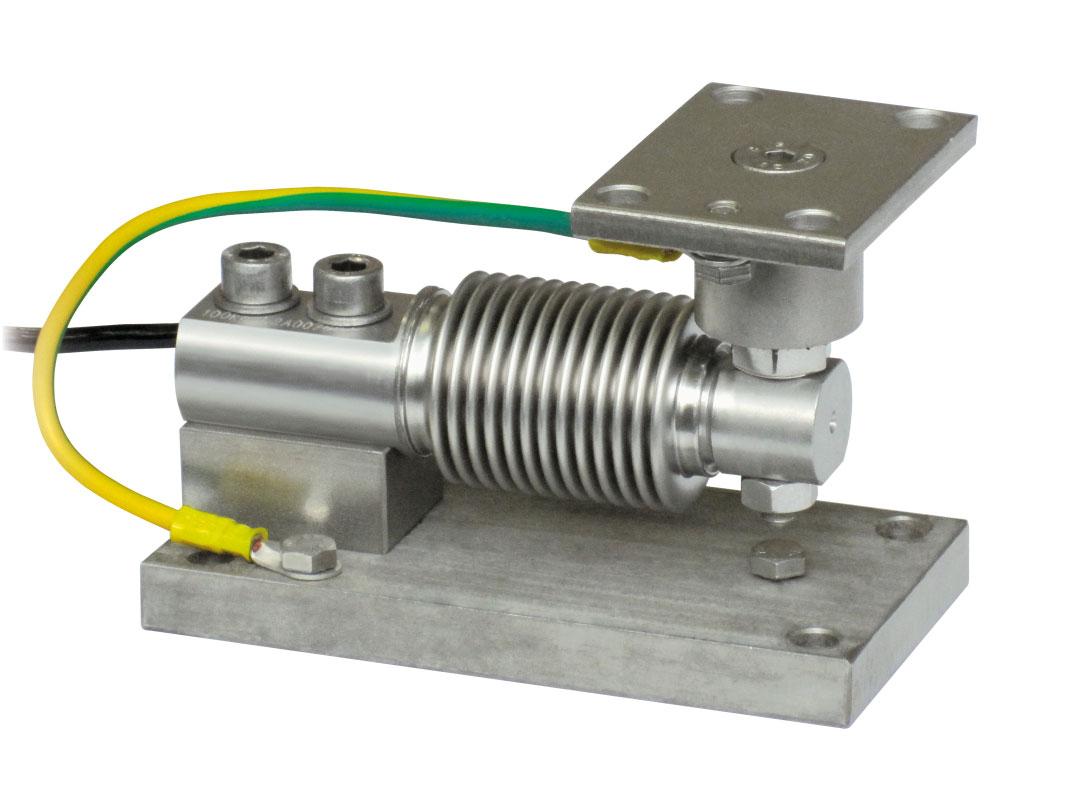
MAX STATIC LOAD
Load cell not included
WEIGHT (kg) FOR LOAD CELLSCODE
DESCRIPTION
Upper plate with a compression joint in AISI 304 stainless steel and rubber.
Lower plate and block in AISI 304 stainless steel. Compensation for any misalignments of the support plates of the structure.
Locking screw to avoid damage during transport and installation. Can be used for systems with at least 3 supports.
During the transport and installation the lock (*) must touch under the load cell. After installation, move the lock away from the load cell. Interconnect the lower plates to the earthing. In case of structure with four-point support, if one-point does not touch the upper part of the mounting kit, you must proceed to insert a shim before fixing the bolts. For the load cell fixing screws (•), provide a tightening torque of 19 Nm.
Up to 500 kg application range
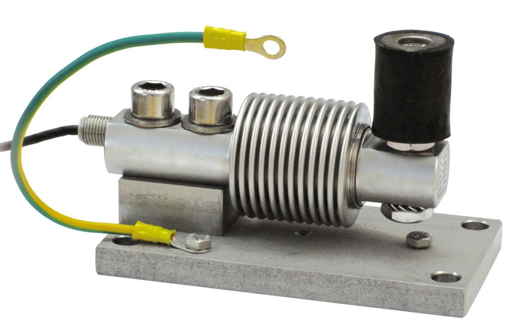
DESCRIPTION
CompressionjointinAISI304stainlesssteelandrubber. LowerplateandblockinAISI304stainlesssteel. Compensationforanymisalignmentsofthesupportplatesofthe structure. Lockingscrewtoavoiddamageduringtransportandinstallation. Canbeusedforsystemswithatleast3supports.
Duringthetransportandinstallationthelock(*) musttouchundertheloadcell.Afterinstallation, movethelockawayfromtheloadcell.
Connectthestructuretobeweighedbymeans ofcopperwire,thenconnectallthelowerplates totheearthingsystem.
Incaseofstructurewithfour-pointsupport,if one-pointdoesnottouchtheupperpartofthe mountingkit,youmustproceedtoinsertashim beforefixingthebolts.
Fortheloadcellfixingscrews(•),providea tighteningtorqueof50Nm.
Series load cells:
Up to 500 kg application range
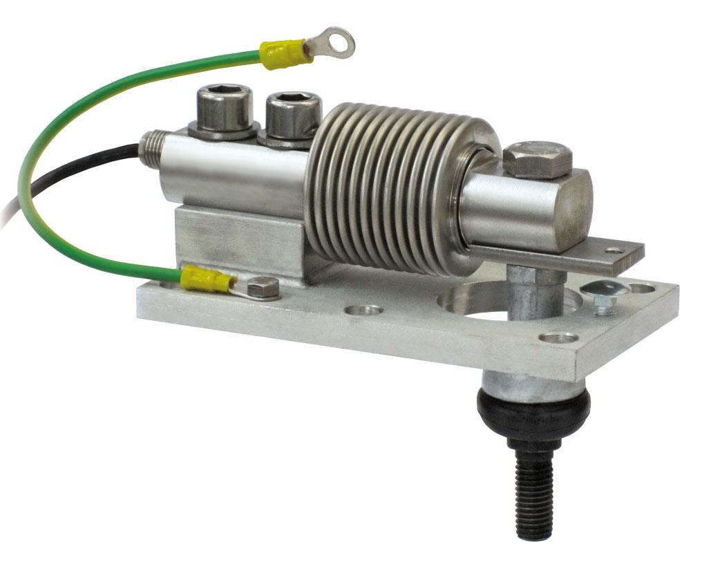
DESCRIPTION
Aluminumalloytensionballjoint. AISI304stainlesssteellowerplate. Lockingscrewtoavoiddamageduringtransportandinstallation.
Duringthetransportandinstallationthelock(*)must touchundertheloadcell.Afterinstallation,movethe lockawayfromtheloadcell.
Connectthestructuretobeweighedbymeansof copperwire,thenconnectallthelowerplatestothe earthingsystem.
Fortheloadcellfixingscrews(•),provideatightening torqueof79Nm.
Series load cells:
Up to 1500 kg application range
Certification EN1090
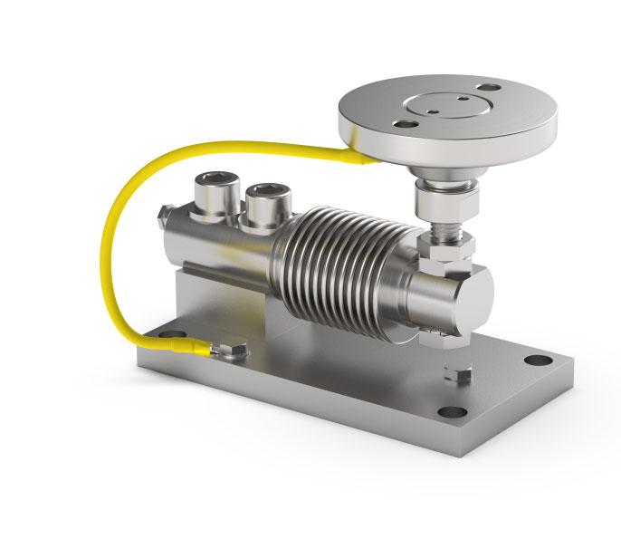
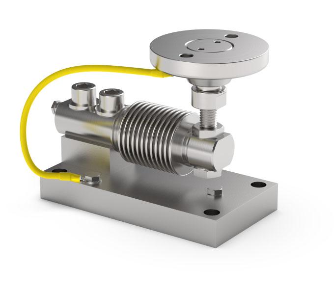
DESCRIPTION
Constraintagainstlateralforcesandanti-tiltbyAISI304stainless steelself-centeringjointfoot. LowerplateandblockinAISI304stainlesssteel. Compensationforanymisalignmentsofthesupportplatesofthe structure. Partialheightadjustment. Lockingscrewtoavoiddamageduringtransportandinstallation.
Duringthetransportandinstallationthelock(*)musttouch undertheloadcell.Afterinstallation,movethelockaway fromtheloadcell.
Interconnecttheplatestotheearthing.
Incaseofstructurewithfour-pointsupport,ifone-point doesnottouchtheupperpartofthemountingkit,youmust proceedtoinsertashimbeforefixingthebolts.
Series load cells:
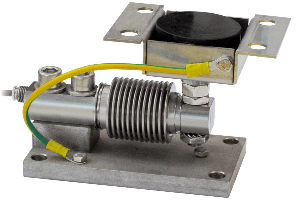
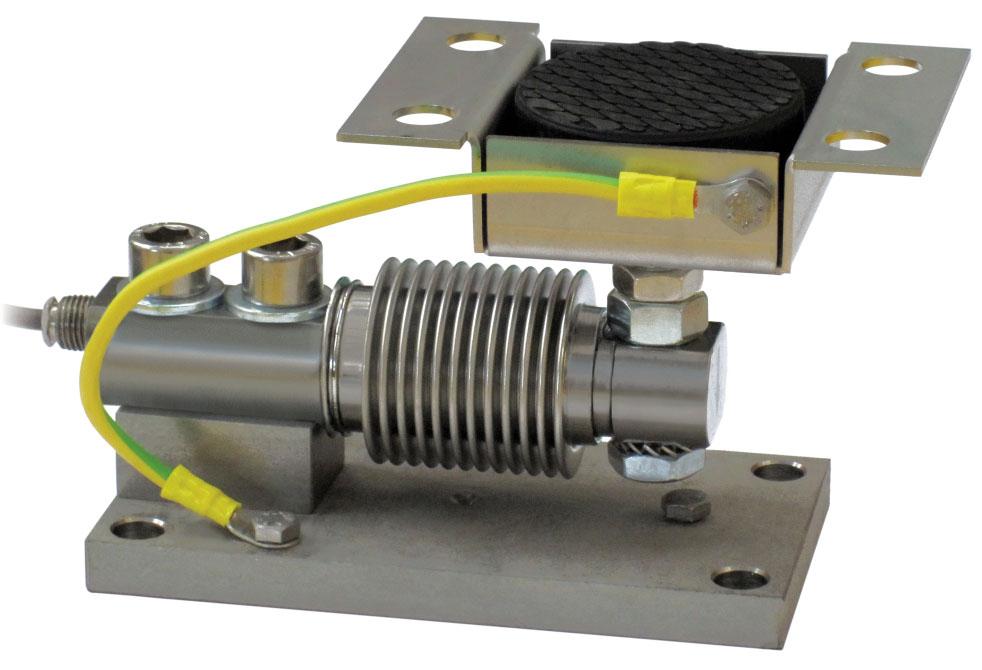
DESCRIPTION
AdjustableupperplateinAISI304stainlesssteel(PPV)or galvanizedsteel(PPVZ).
LowerplateandblockinAISI304stainlesssteel.
Constraintagainstlateralforcesandanti-tiltbyAISI304stainless steel(TFPV,TFPV2000)orgalvanizedsteel(TFPVZ)self-centering jointfoot.
Compensationforanymisalignmentsofthesupportplatesofthe structure.
Partialheightadjustment.
Lockingscrewtoavoiddamageduringtransportandinstallation.
Duringthetransportandinstallationthelock(*)musttouch undertheloadcell.Afterinstallation,movethelockaway fromtheloadcell.
Interconnecttheplatestotheearthing.
Incaseofstructurewithfour-pointsupport,ifone-point doesnottouchtheupperpartofthemountingkit,youmust proceedtoinsertashimbeforefixingthebolts.
Fortheloadcellfixingscrews(•),provideatightening torqueof50Nm.
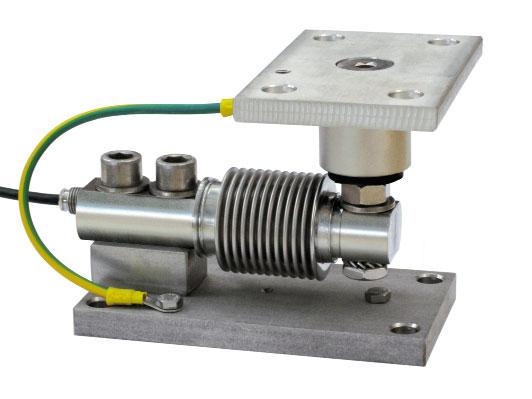
DESCRIPTION
UpperplatewithacompressionjointinAISI304stainlesssteel andrubber.
LowerplateandblockinAISI304stainlesssteel. Compensationforanymisalignmentsofthesupportplatesofthe structure. Lockingscrewtoavoiddamageduringtransportandinstallation. Canbeusedforsystemswithatleast3supports.
Duringthetransportandinstallationthelock(*) musttouchundertheloadcell.Afterinstallation, movethelockawayfromtheloadcell. Interconnectthelowerplatestotheearthing. Incaseofstructurewithfour-pointsupport,ifonepointdoesnottouchtheupperpartofthemounting kit,youmustproceedtoinsertashimbeforefixing thebolts.
Fortheloadcellfixingscrews(•),provideatightening torqueof50Nm.
Series load cells:
Up to 2000 kg application range
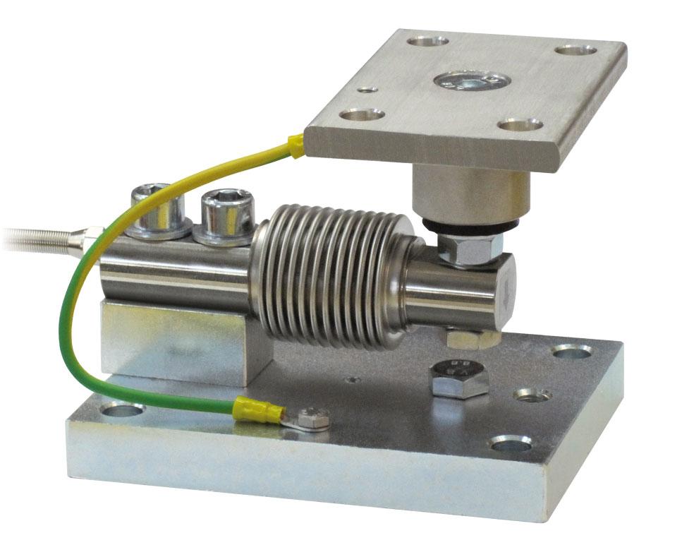
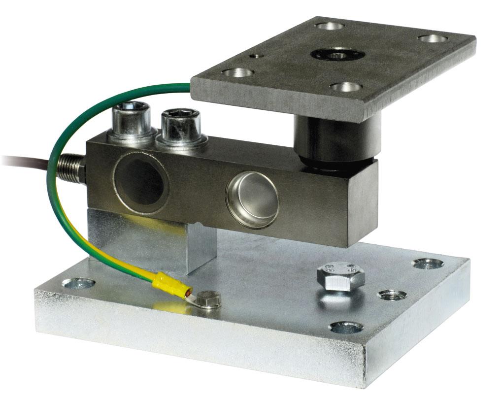
DESCRIPTION
UpperplatewithacompressionjointinAISI304stainlesssteel andrubber.
Lowerplateandblockingalvanizedsteel. Compensationforanymisalignmentsofthesupportplatesofthe structure.
Lockingscrewtoavoiddamageduringtransportandinstallation. Canbeusedforsystemswithatleast3supports.
Duringthetransportandinstallationthelock(*)musttouchunder theloadcell.Afterinstallation,movethelockawayfromtheloadcell. Interconnectthelowerplatestotheearthing.
Incaseofstructurewithfour-pointsupport,ifone-pointdoesnot touchtheupperpartofthemountingkit,youmustproceedto insertashimbeforefixingthebolts.
Fortheloadcellfixingscrews(•),provideatighteningtorqueof79Nm.
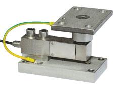
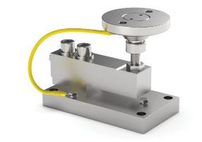
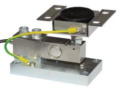
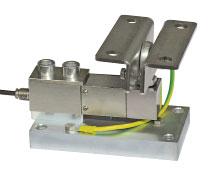
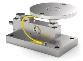


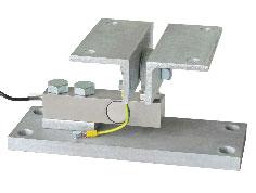
Series load cells:
Up to 2000 kg application range
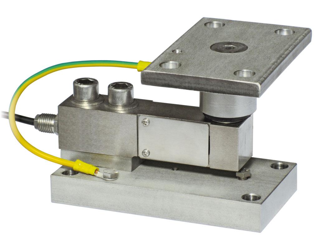
DESCRIPTION
Upper plate with a compression joint in AISI 304 stainless steel and rubber.
Lower plate and block in AISI 304 stainless steel (TF500, TF2000) or in galvanized steel (TF2000Z).
Compensation for any misalignments of the support plates of the structure.
Locking screw to avoid damage during transport and installation. Can be used for systems with at least 3 supports.
During the transport and installation the lock (*) must touch under the load cell. After installation, move the lock away from the load cell. Interconnect the plates to the earthing. In case of structure with four-point support, if one-point does not touch the upper part of the mounting kit, you must proceed to insert a shim before fixing the bolts. For the load cell fixing screws (•), provide a tightening torque of 50 Nm for TF500/TF2000 and 79 Nm for TF2000Z.
Company reserves the
Series load cells:
Up to 2000 kg application range
Certification EN1090
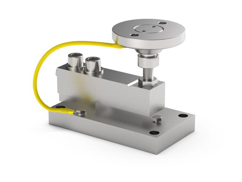
FOR LOAD CELLS
cell not included.
DESCRIPTION
Constraint against lateral forces and anti-tilt by AISI 304 stainless steel self-centering joint foot.
Lower plate and block in AISI 304 stainless steel.
Compensation for any misalignments of the support plates of the structure.
Adjustable height.
Locking screw to avoid damage during transport and installation.
During the transport and installation the lock (*) must touch under the load cell. After installation, move the lock away from the load cell.
Interconnect the plates to the earthing.
In case of structure with four-point support, if one-point does not touch the upper part of the mounting kit, you must proceed to insert a shim before fixing the bolts.
The Company reserves the right to make changes to the technical data, drawings and images without notice.
Series load cells:
Up to 2000 kg application range

Load cell not included.
DESCRIPTION
Adjustable upper plate in AISI 304 stainless steel (PPV) or galvanized steel (PPVZ).
Lower plate and block in AISI 304 stainless steel (PV) or galvanized steel (PVZ).
Constraint against lateral forces and anti-tilt by AISI 304 stainless steel (TFPV, TFPV2000) or galvanized steel (TFPVZ) self-centering joint foot.
Compensation for any misalignments of the support plates of the structure.
Adjustable height.
Locking screw to avoid damage during transport and installation.
During the transport and installation the lock (*) must touch under the load cell. After installation, move the lock away from the load cell.
Interconnect the plates to the earthing.
In case of structure with four-point support, if one-point does not touch the upper part of the mounting kit, you must proceed to insert a shim before fixing the bolts.
For the load cell fixing screws (•), provide a tightening torque of 50 Nm for PV and 79 Nm for PVZ.
Series load cells:
Up to 2000 kg application range
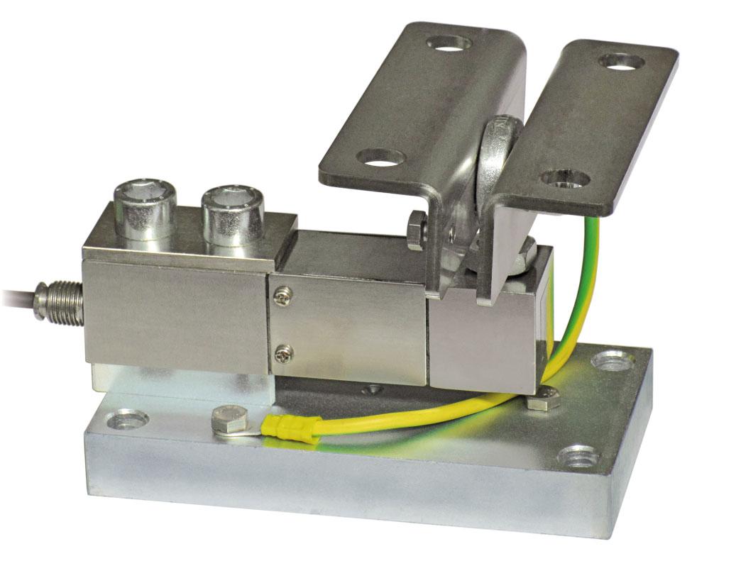
MAX STATIC LOADFOR LOAD CELLS
kg
NET WEIGHT (kg)CODE
2000 FTK-FTKL-FTP-FT-P-FTZ2.7TFPS2000
2000 FTK-FTKL-FTP-FT-P-FTZ2.7TFPS2000INOX
Load cell not included.
DESCRIPTION
AISI304stainlesssteelupperplate. Lowerplateandblockingalvanizedsteel(TFPS2000)orin stainlesssteel(TFPS2000INOX). Constraintagainstlateralforcesandanti-tiltbymeansofball-andsocketjointwithnutingalvanizedC40steel(TFPS2000)orin stainlesssteel(TFPS2000INOX). Compensationforanymisalignmentsofthesupportplatesofthe structure. Adjustableheight. Lockingscrewtoavoiddamageduringtransportandinstallation.
Duringthetransportandinstallationthelock(*)musttouch undertheloadcell.Afterinstallation,movethelockaway fromtheloadcell.
Interconnecttheplatestotheearthing.
Incaseofstructurewithfour-pointsupport,ifone-point doesnottouchtheupperpartofthemountingkit,youmust proceedtoinsertashimbeforefixingthebolts. Fortheloadcellfixingscrews(•),provideatighteningtorque of79Nm.
Series load cells:
Up to 5000 kg application range Certification EN1090
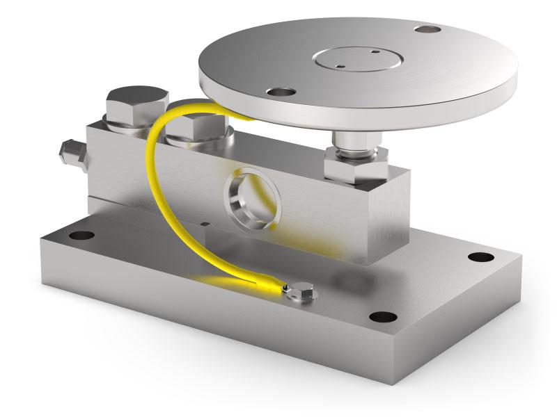
DESCRIPTION
Constraint against lateral forces and anti-tilt by AISI 304 stainless steel self-centering joint foot.
Lower plate and block in AISI 304 stainless steel. Compensation for any misalignments of the support plates of the structure.
Adjustable height.
Locking screw to avoid damage during transport and installation.
DIMENSIONS AND TECHNICAL SPECIFICATIONS
Interconnect the plates to the earthing. In case of structure with four-point support, if one-point does not touch the upper part of the mounting kit, you must proceed to insert a shim before fixing the bolts.
Series load cells:
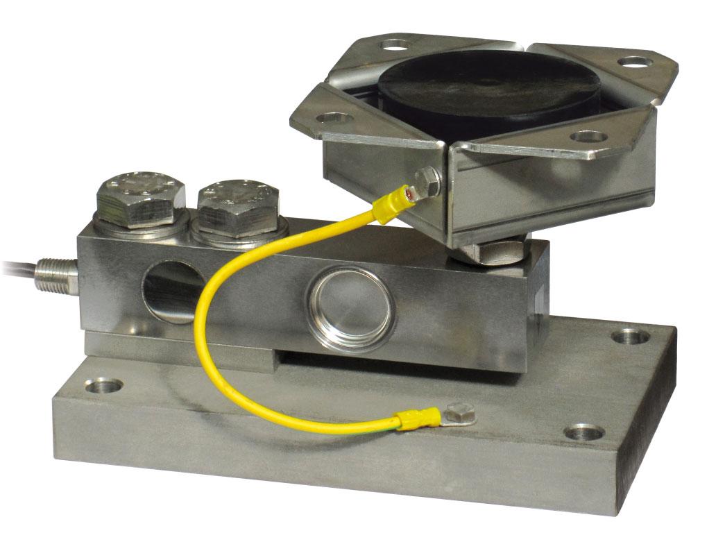
DESCRIPTION
Adjustable upper plate in AISI 304 stainless steel (PPV80) or galvanized steel (PPV60Z)
Lower plate and block in AISI 304 stainless steel (PV80) or galvanized steel (PV60Z).
Constraint against lateral forces and anti-tilt by AISI 304 stainless steel (PV80) or galvanized steel (PV60Z) self-centering joint foot. Compensation for any misalignments of the support plates of the structure.
Adjustable height.
Interconnect the plates to the earthing.
In case of structure with four-point support, if one-point does not touch the upper part of the mounting kit, you must proceed to insert a shim before fixing the bolts. For the load cell fixing screws (•), provide a tightening torque of 280 Nm.
Series load cells:
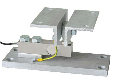
MAX STATIC LOAD FOR LOAD CELLS
NET WEIGHT (kg)CODE
Load cell not included.
DESCRIPTION
Upper plate, lower plate and block in galvanized steel. Constraint against lateral forces and anti-tilt by ball-and-socket joint. Compensation for any misalignments of the support plates of the structure.
Adjustable height.
Interconnect the plates to the earthing.
In case of structure with four-point support, proceed to the height adjustment, if one-point does not touch the upper part of the mounting kit.
For the load cell fixing screws (•), provide a tightening torque of 290 Nm for PS and 690 Nm for PS10T.
The Company reserves the right to make changes to the
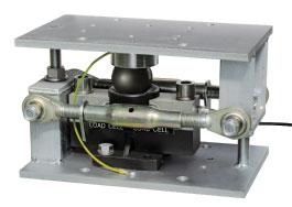
upto50000kg
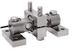
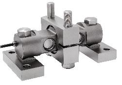
upto60klb/27ton
Series load cells:
Up to 50000 kg application range
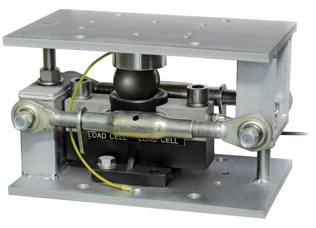
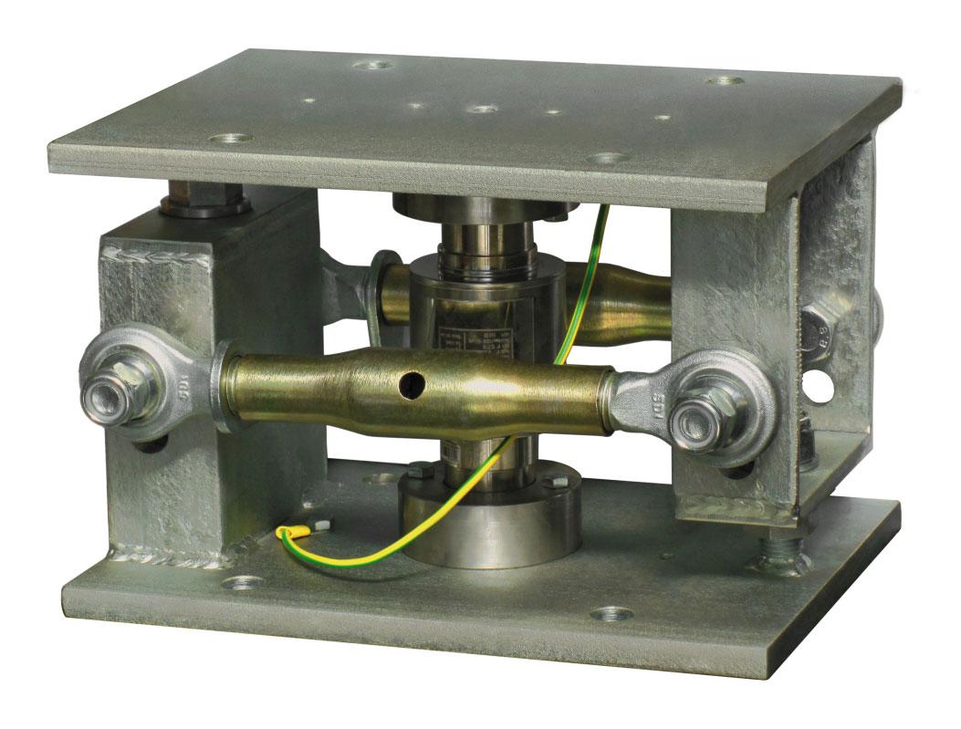
DOUBLE SHEAR BEAM load cellsCOLUMN load cells
DESCRIPTION
Galvanized steel upper and lower plate.
Galvanized steel plate (for DOUBLE SHEAR BEAM load cell).
Upper and lower bases (for COLUMN load cell).
Two integrated galvanized steel stay rods with dual ball-andsocket joints suitable to counter the lateral force.
Anti-tilt constraint consisting of two threaded rods with self-locking nut.
DIMENSIONS AND TECHNICAL SPECIFICATIONS
Upper and lower plates 3 must rest completely on not deformable surfaces. To ensure the stability of the structure, the system designer must predict any further precaution against side shifts and anti-tilt in function of: knocks and vibrations, wind effect, seismic conditions and hardness of support structure.
for DOUBLE SHEAR BEAM load cells (DTL):
Install the weighed system using only the mounting kit without the load cell 1 and inserting in its place a piece of pipe (Ø40x220 mm): unscrewing the nuts 5 and take off one of the two threaded rods 4 and the plate 2
To finish the installation (weldings, etc..), take off the piece of pipe and the plate 2 ; to place the plate 2 on the load cell 1 and insert them in mounting kit.
Fix the load cell and the plate by using the bolts provided. Connect lower and upper plates 3 to the earthing system 9 then loosen nuts 6 ; verify that the threaded rod 8 slides into the hole; turn anti-tilt nuts 7 to a distance of 1 mm from plate.
for COLUMN load cells (COL - COK):
Example of weighing structures subject to knocks or wind effect


3 SUPPORTS STRUCTURES
4 SUPPORTS STRUCTURES
1 Load cell.
2 Galvanized steel plate (PIATTODTL).
3 Galvanized steel upper and lower plates (PIACOKDTL).
4 Galvanized steel turnbuckle with horizontal constrainer function (TENDITORE300).
5 Self-locking nut Ø18.
6 Nut Ø22 to be used as jack.
7 Anti-tilt self-locking nut Ø22.
8 Threaded rod Ø22.
9 Copper wire for earthing connection.
Install the weighed system using only the mounting kit without the load cell 1 and inserting in its place a piece of pipe (Ø44x152 mm): unscrewing the nuts 5 , take off one of the two threaded rods 4 and the lower base 2
To finish the installation (weldings, etc..), take off the piece of pipe and the lower base 2 ; replace the load cell 1 on the lower base 2 and insert them in mounting kit.
Connect lower and upper plates 3 to the earthing system 9 then loosen nuts 6 ; verify that the threaded rod 8 slides into the hole; turn anti-tilt nuts 7 to a distance of 1 mm from plate.
1 Load cell.
2 Upper and lower bases.
3 Galvanized steel upper and lower plates (PIACOKDTL).
4 Galvanized steel turnbuckle with horizontal constrainer function (TENDITORE300).
5 Self-locking nut Ø18.
6 Nut Ø22 to be used as jack.
7 Anti-tilt self-locking nut Ø22.
8 Threaded rod Ø22.
9 Copper wire for earthing connection.
The Company reserves the right to make changes to the technical data, drawings and images without notice.
Series load cells:
Up to 60 klb/27 ton application range
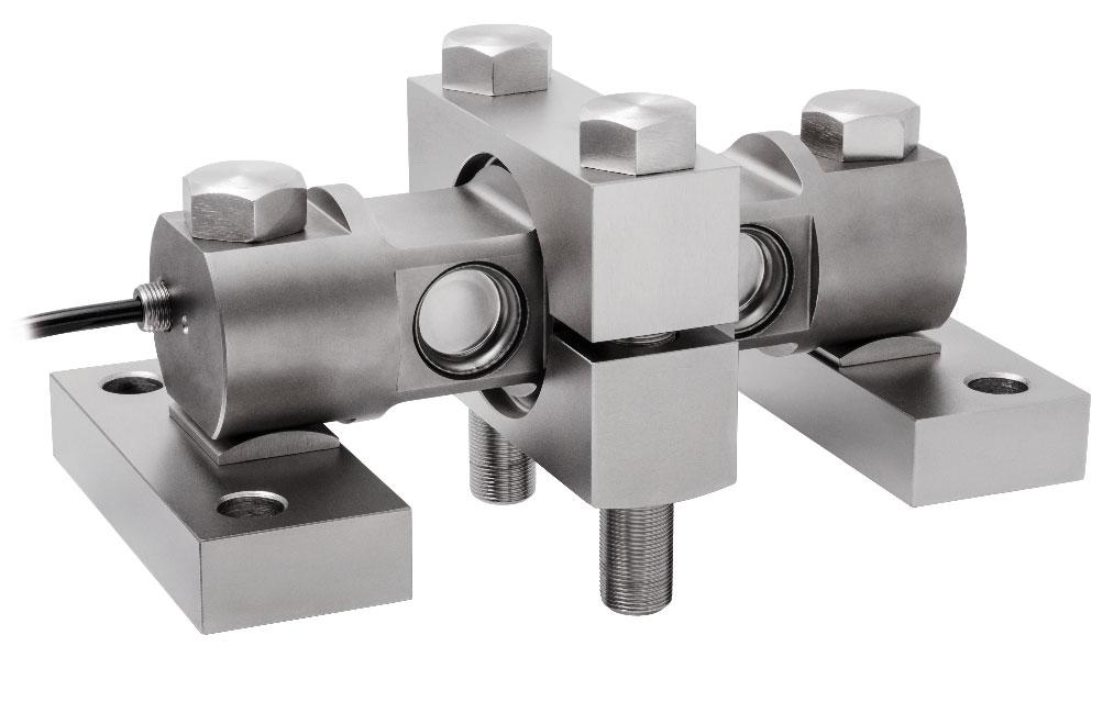
MAX STATIC LOADFOR LOAD CELLS
Load cell not included.
The base plates must be placed on non-deformable surface. To ensure the stability of the structure, the system designer must predict any further precaution against side shifts and anti-tilt in function of: knocks and vibrations, wind effect, seismic conditions and hardness of support structure. DIMENSIONS AND TECHNICAL SPECIFICATIONS
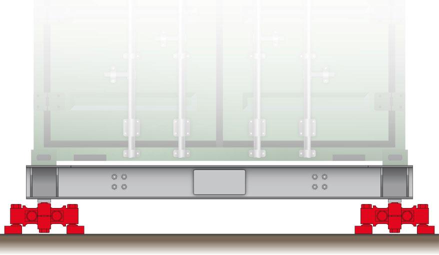
Example of application: container weighing
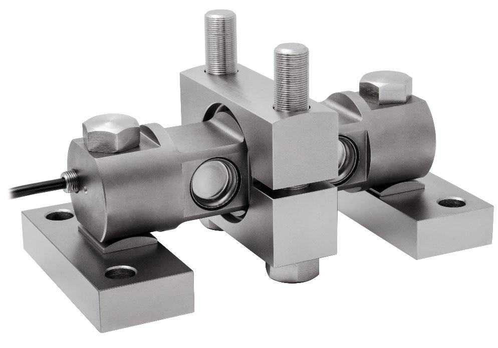
DESCRIPTION
Nickel-plated steel alloy mounting kit for rigid attachment of the load cell. It prevents horizontal movement.
NET WEIGHT (kg)
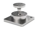
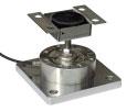
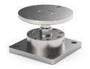
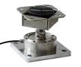
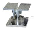
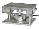
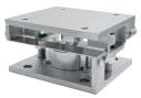
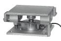
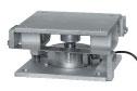
Series load cells:
Up to 2000 kg application range
Certification EN1090
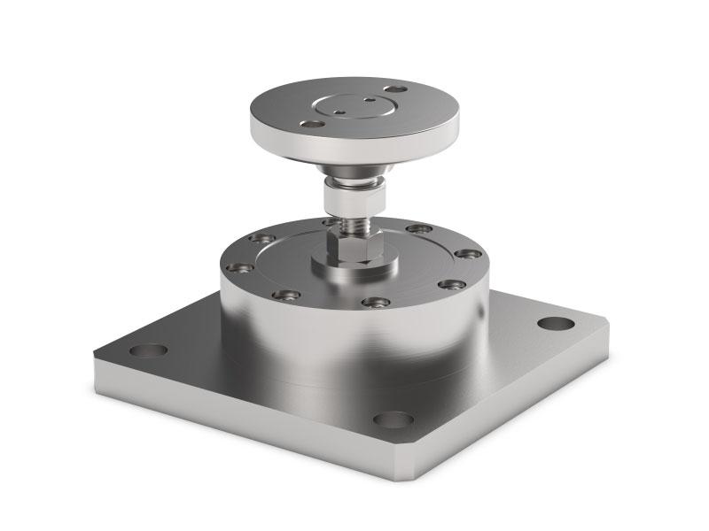
MAX STATIC LOAD FOR LOAD CELLS
DESCRIPTION
Constraint against lateral forces and anti-tilt by AISI 304 stainless steel self-centering joint foot.
Compensation for any misalignments of the support plates of the structure.
Adjustable height.
DIMENSIONS AND TECHNICAL SPECIFICATIONS
Finished the installation by means of a copper wire, connect the upper supporting plate with the lower supporting plate, then connect all the lower plates to the earthing system. In case of structure with four-point support, if one-point does not touch the support base of the foot, you must proceed to adjust foot height.
The Company reserves the right to make changes to the technical data, drawings and images without notice.
Series load cells:
Up to 2000 kg application range
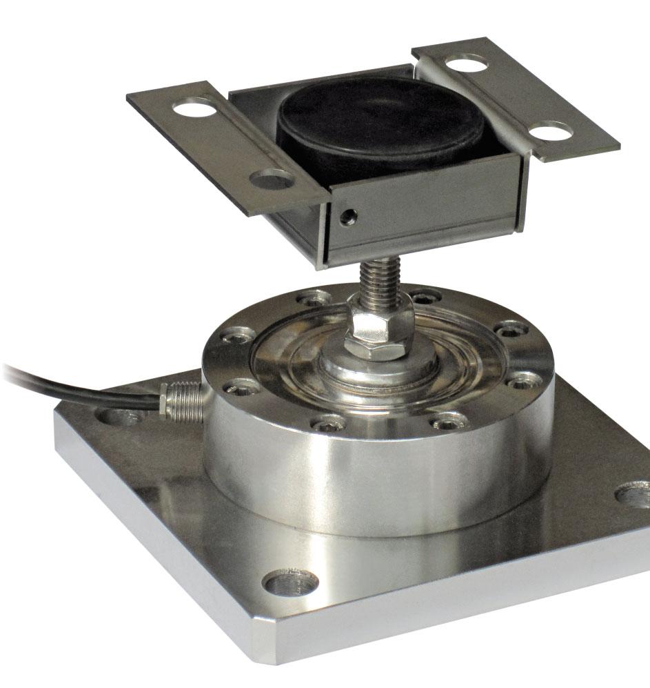

DESCRIPTION
Adjustable upper plate in AISI 304 stainless steel (PPV).
Constraint against lateral forces and anti-tilt by stainless steel self-centering joint foot.
Compensation for any misalignments of the support plates of the structure.
Adjustable height.
DIMENSIONS AND TECHNICAL SPECIFICATIONS
Finished the installation by means of a copper wire, connect the upper supporting plate with the lower supporting plate, then connect all the lower plates to the earthing system. In case of structure with four-point support, if one-point does not touch the support base of the foot, you must proceed to adjust foot height.
The Company reserves the right to make changes to the
Series load cells:
Up to 5000 kg application range
Certification EN1090
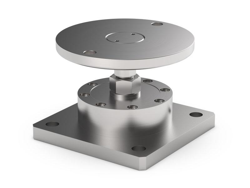
MAX STATIC LOAD FOR LOAD CELLS
Load cell not included.
DESCRIPTION
Constraint against lateral forces and anti-tilt by AISI 304 stainless steel self-centering joint foot.
Compensation for any misalignments of the support plates of the structure.
Adjustable height.
DIMENSIONS AND TECHNICAL SPECIFICATIONS
Finished the installation by means of a copper wire, connect the upper supporting plate with the lower supporting plate, then connect all the lower plates to the earthing system. In case of structure with four-point support, if one-point does not touch the support base of the foot, you must proceed to adjust foot height.
The Company reserves the right to make changes to the technical data, drawings and images without notice.
Series load cells:
Up to 5000 kg application range
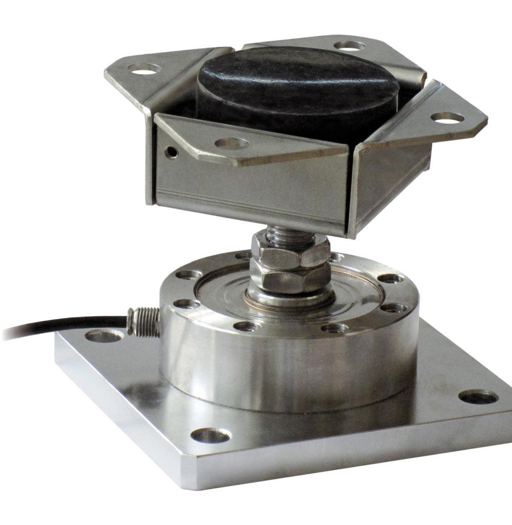

MAX STATIC LOAD FOR LOAD CELLS Load cell not included.
DESCRIPTION
Adjustable upper plate in AISI 304 stainless steel (PPV80).
Constraint against lateral forces and anti-tilt by stainless steel self-centering joint foot.
Compensation for any misalignments of the support plates of the structure.
Adjustable height.
DIMENSIONS AND TECHNICAL SPECIFICATIONS
Finished the installation by means of a copper wire, connect the upper supporting plate with the lower supporting plate, then connect all the lower plates to the earthing system. In case of structure with four-point support, if one-point does not touch the support base of the foot, you must proceed to adjust foot height.
The Company reserves the right to make changes to the technical data, drawings and images without notice.
Series load cells:
Up to 5000 kg application range
Load cell not included.
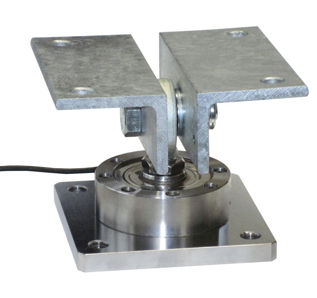
DESCRIPTION
Adjustable upper plate in hot galvanized steel. Constraint against lateral forces and anti-tilt by ball-and-socket joint Compensation for any misalignments of the support plates of the structure.
Adjustable height.
DIMENSIONS AND TECHNICAL SPECIFICATIONS
Finished the installation by means of a copper wire, connect the upper supporting plate with the lower supporting plate, then connect all the lower plates to the earthing system.
The Company reserves the right to make changes to the technical data, drawings and images without notice.
Series load cells:
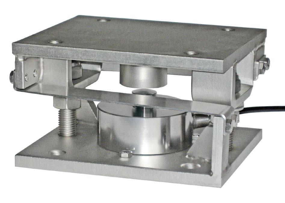
15000 –
15000 –
15000
15000
Load cell not included.
DESCRIPTION
V10000/V10000EN1090
HORIZONTAL CONSTRAINTS MAX STATIC LOAD
CBL(250÷12500kg)-CBX(15000kg) CX(1000÷15000kg)5.7V10000
CBL(250÷12500kg)-CBX(15000kg) CX(1000÷15000kg)6.9V10275
CBL(250÷12500kg)-CBX(15000kg) CX(1000÷15000kg)5.7V10000EN1090
CBL(250÷12500kg)-CBX(15000kg) CX(1000÷15000kg)6.9V10275EN1090
AISI304stainlesssteelupperandlowerplates.
AISI304stainlesssteellaminasagainstlateralforces. Anti-tiltconstraintconsistingoftwothreadedrodswithself-lockingnut.
HORIZONTALCONSTRAINTS
ORIENTATION
INSTRUCTURESWITH 3-POINTSUPPORT
COMPLEMENTARY ACCESSORIES
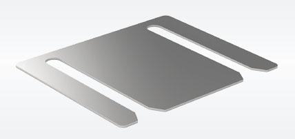
HORIZONTALCONSTRAINTS
ORIENTATION INSTRUCTURESWITH 4-POINTSUPPORT
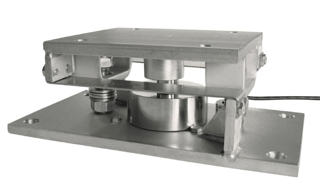
Example of application
V10275/V10275EN1090


DESCRIPTIONCODE
AISI304stainlesssteelshimforV10000/V10000EN1090:
h0.5mm
Upperandlowerplates 2 mustrestcompletelyonnotdeformable surfaces.Toensurethestabilityofthestructure,thesystemdesigner mustpredictanyfurtherprecautionagainstsideshiftsandanti-tiltin functionof:knocksandvibrations,windeffect,seismicconditions andhardnessofsupportstructure.
Installtheweighedsystemusingonlythemountingkitwithout theloadcell 1 andinsertinginitsplaceapieceofpipe(1-2mm higherthantheloadcell).
Tofinishtheinstallation(weldings,etc..),removethepieceofpipe andthenremovingtheboltstofixthetheloadcell 7 insertthe loadcell 1 inmountingkit.
Connectlowerandupperplates 2 totheearthingsystemthen loosennuts 5 ;verifythatthethreadedrod 4 slidesintothehole; turnanti-tiltnuts 6 toadistanceof1mmfromplate. Tightenthethreeboltstofixtheloadcell 7
V10275/V10275EN1090 - Lower plate
- Lower plate
1 Loadcell.
2 AISI304stainlesssteelupperandlower plates.
3 AISI304stainlesssteellaminaswith horizontalconstraintfunction.
4 Threadedrod.
5 Nuttobeusedasjack.
6 Anti-tiltself-lockingnut.
7 M6boltstofixtheloadcell.
Series load cells:
Up to 15000 kg application range
DESCRIPTION
UpperandlowerplatesingalvanizedS355JRconstructionsteel. AISI304stainlesssteellaminasagainstlateralforces. Anti-tiltconstraintconsistingoftwothreadedrodswithself-lockingnut.
MAX STATIC LOAD FOR LOAD CELLS
Load cell not included.
HORIZONTALCONSTRAINTS ORIENTATION INSTRUCTURESWITH 3-POINTSUPPORT
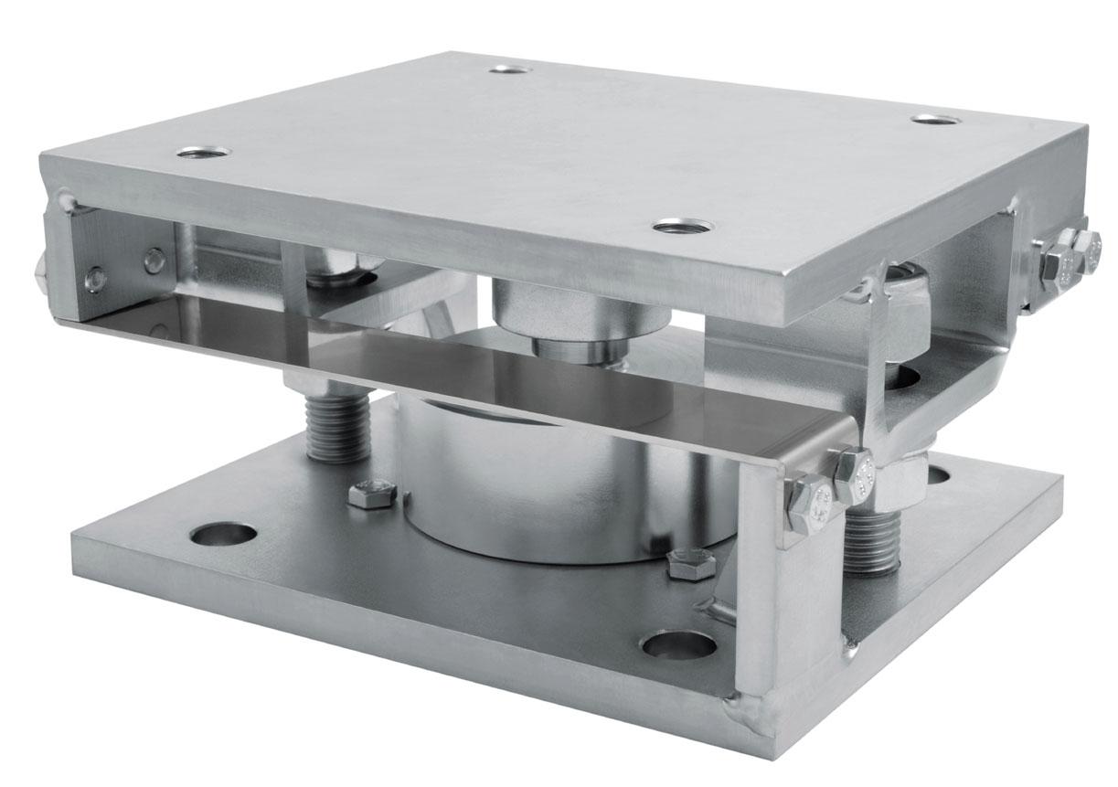
NET WEIGHT (kg)CODE
CBL(250÷12500kg)-CBX(15000kg) CX(1000÷15000kg)5.7Z10000
Example of application
COMPLEMENTARY ACCESSORIES
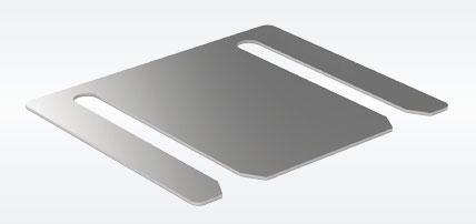
HORIZONTALCONSTRAINTS ORIENTATION INSTRUCTURESWITH 4-POINTSUPPORT
HORIZONTAL CONSTRAINTS


DESCRIPTIONCODE
AISI304stainlesssteelshim:
h0.5mm
DIMENSIONS
Upperandlowerplates 2 mustrestcompletelyonnotdeformable surfaces.Toensurethestabilityofthestructure,thesystemdesigner mustpredictanyfurtherprecautionagainstsideshiftsandanti-tiltin functionof:knocksandvibrations,windeffect,seismicconditions andhardnessofsupportstructure.
Installtheweighedsystemusingonlythemountingkitwithout theloadcell 1 andinsertinginitsplaceapieceofpipe(1-2mm higherthantheloadcell).
Tofinishtheinstallation(weldings,etc..),removethepieceofpipe andthenremovingtheboltstofixthetheloadcell 7 insertthe loadcell 1 inmountingkit.
Connectlowerandupperplates 2 totheearthingsystemthen loosennuts 5 ;verifythatthethreadedrod 4 slidesintothehole; turnanti-tiltnuts 6 toadistanceof1mmfromplate.
Tightenthethreeboltstofixtheloadcell 7
1 Loadcell.
2 Upperandlowerplatesingalvanized S355JRconstructionsteel.
3 AISI304stainlesssteellaminaswith horizontalconstraintfunction.
4 Threadedrod.
5 Nuttobeusedasjack.
6 Anti-tiltself-lockingnut.
7 M6boltstofixtheloadcell.
Series load cells:
Up to 100000 kg application range
DESCRIPTION
AISI304stainlesssteelupperandlowerplates. AISI304stainlesssteellaminasagainstlateralforces. Anti-tiltconstraintconsistingoftwothreadedrodswithself-lockingnut.
kg
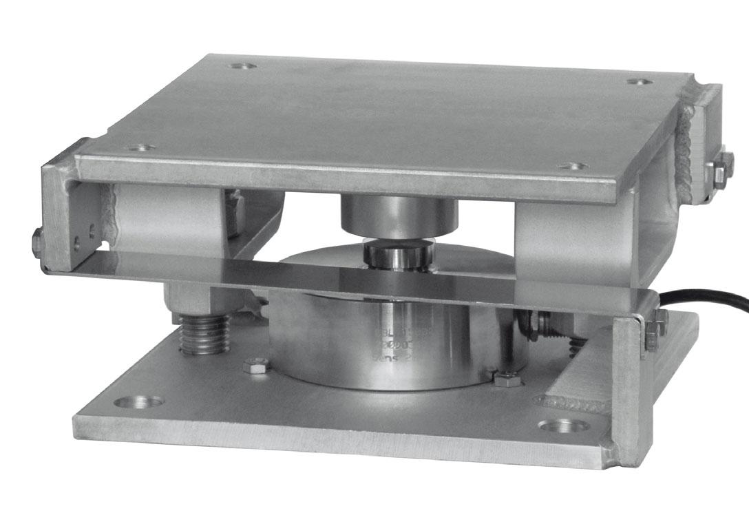
MAX STATIC LOAD FOR LOAD CELLS
NET WEIGHT (kg)CODE
30000 –CBL(15000kg)-CBX(30000kg)-CX(30000kg)9V15000
50000 –CBL(30000kg)-CBX(50000kg)17.5V30000
100000 –CBL(50000kg)-CBL(100000kg)33.5V100000
30000 CBL(15000kg)-CBX(30000kg)-CX(30000kg)9V15000EN1090
50000 CBL(30000kg)-CBX(50000kg)17.5V30000EN1090
100000 CBL(50000kg)-CBL(100000kg)33.5V100000EN1090
Load cell not included.
HORIZONTALCONSTRAINTS ORIENTATION INSTRUCTURESWITH 3-POINTSUPPORT
HORIZONTALCONSTRAINTS ORIENTATION INSTRUCTURESWITH 4-POINTSUPPORT
HORIZONTAL CONSTRAINTS
Example of application


DESCRIPTIONCODE
AISI304stainlesssteelshim:
V15000/V15000EN1090
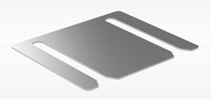
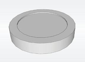
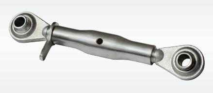
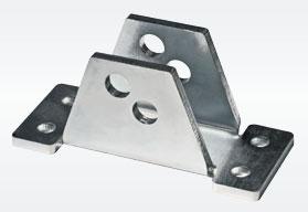
V30000/V30000EN1090
V100000/V100000EN1090
V15000/V15000EN1090
V30000/V30000EN1090
h0.5mm h1mm h2mm
h0.5mm h1mm h2mm
h0.5mm h1mm h2mm
SPVZ1505 SPVZ151 SPVZ152
SPVZ3005 SPVZ301 SPVZ302
SPVZ10005 SPVZ1001
SPVZ1002
AISI304stainlesssteeladapter: forloadcells forloadcells forloadcells
V100000/V100000EN1090
Galvanizedsteelturnbucklewithdualball-and-socket.
Netweight:2.10kg
Ø82mm Ø100mm Ø126mm
Workingload:2500kgUltimateoverload:10000kg
GalvanizedsteelanchorplateforTENDITORE300
Netweight:1.5kg
ADAT100
ADAT126
ADAT165
TENDITORE300
PTEND
Upperandlowerplates 2 mustrestcompletelyonnotdeformablesurfaces.To ensurethestabilityofthestructure,thesystemdesignermustpredictanyfurther precautionagainstsideshiftsandanti-tiltinfunctionof:knocksandvibrations, windeffect,seismicconditionsandhardnessofsupportstructure.
Installtheweighedsystemusingonlythemountingkitwithouttheloadcell 1 andinsertinginitsplaceapieceofpipe(1-2mmhigherthantheloadcell). Tofinishtheinstallation(weldings,etc..),removethepieceofpipeandthen removingtheboltstofixthetheloadcell 7 inserttheloadcell 1 inmounting kit.
Connectlowerandupperplates 2 totheearthingsystemthenloosennuts 5 ;verifythatthethreadedrod 4 slidesintothehole;turnanti-tiltnuts 6 toa distanceof1mmfromplate.
Tightenthethreeboltstofixtheloadcell 7
V15000/V15000EN1090 1021020016010 47 20M12x1.75 Ø17 M20x2.540 9 kg
V30000/V30000EN1090 132 12 250185 12 7032.5M18x2.5 Ø20 M24x3 60 17 kg V100000/V100000EN1090 15515320250159535M20x2.5 Ø23 M30x3.570 34 kg
1 Loadcell.
2 AISI304stainlesssteelupperandlowerplates.
3 AISI304stainlesssteellaminaswithhorizontal constraintfunction.
4 Threadedrod.
5 Nuttobeusedasjack.
6 Anti-tiltself-lockingnut.
7 M6boltstofixtheloadcell.
Application example: how to make further horizontal constraints with the TENDITORE300 accessory
CONSTRAINTSPLACEMENTON3/4SUPPORTS: thehorizontalconstraintscanbepositionedbothon supportsandonthefoursides,centrallybetweentwo supports.
Series load cells:
Up to 100000 kg application range
DESCRIPTION
UpperandlowerplatesingalvanizedS355JRconstructionsteel. AISI304stainlesssteellaminasagainstlateralforces. Anti-tiltconstraintconsistingoftwothreadedrodswithself-lockingnut.
kg
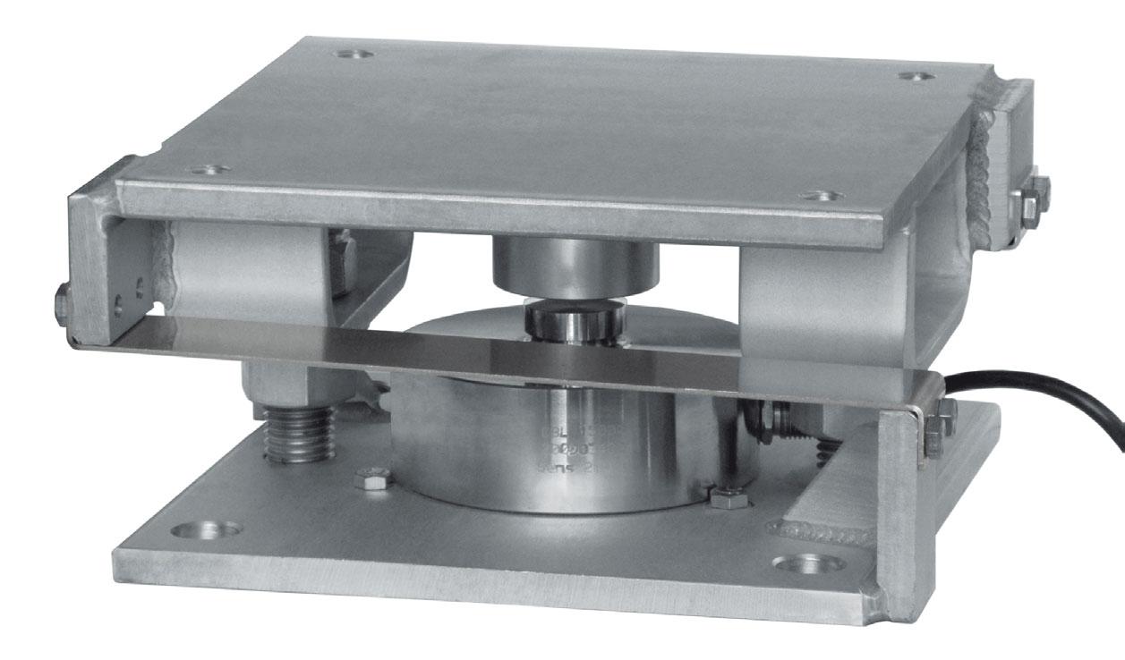
MAX STATIC LOAD FOR LOAD CELLS
(kg)CODE
30000 CBL(15000kg)-CBX(30000kg)-CX(30000kg)9Z15000
50000 CBL(30000kg)-CBX(50000kg)17.5Z30000
100000 CBL(50000kg)-CBL(100000kg)33.5Z100000
HORIZONTALCONSTRAINTS ORIENTATION
INSTRUCTURESWITH 3-POINTSUPPORT
HORIZONTALCONSTRAINTS ORIENTATION
INSTRUCTURESWITH 4-POINTSUPPORT
Example of application

HORIZONTAL CONSTRAINTS


DESCRIPTIONCODE
AISI304stainlesssteelshim:
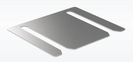
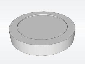

Z15000 h0.5mm h1mm h2mm
Z30000 h0.5mm h1mm h2mm
Z100000 h0.5mm h1mm h2mm
Z15000 Z30000
SPVZ1505
SPVZ151
SPVZ152
SPVZ3005
SPVZ301
SPVZ302
SPVZ10005
SPVZ1001
SPVZ1002
AISI304stainlesssteeladapter: forloadcells forloadcells forloadcells
Z100000
Galvanizedsteelturnbucklewithdualball-and-socket.
Netweight:2.10kg
Ø100mm Ø126mm
Workingload:2500kgUltimateoverload:10000kg
GalvanizedsteelanchorplateforTENDITORE300
Netweight:1.5kg
Upperandlowerplates 2 mustrestcompletelyonnotdeformablesurfaces.To ensurethestabilityofthestructure,thesystemdesignermustpredictanyfurther precautionagainstsideshiftsandanti-tiltinfunctionof:knocksandvibrations, windeffect,seismicconditionsandhardnessofsupportstructure.
Installtheweighedsystemusingonlythemountingkitwithouttheloadcell 1 andinsertinginitsplaceapieceofpipe(1-2mmhigherthantheloadcell).
Tofinishtheinstallation(weldings,etc..),removethepieceofpipeandthen removingtheboltstofixthetheloadcell 7 inserttheloadcell 1 inmounting kit.
Connectlowerandupperplates 2 totheearthingsystemthenloosennuts 5 ;verifythatthethreadedrod 4 slidesintothehole;turnanti-tiltnuts 6 toa distanceof1mmfromplate.
Tightenthethreeboltstofixtheloadcell 7
Z150001021020016010 47 20M12x1.75 Ø17 M20x2.540 9 kg
Z30000132 12 250185 12 70 32.5 M18x2.5Ø20 M24x3 60 17 kg
Z10000015515320250159535M20x2.5Ø23M30x3.570 34 kg
1 Loadcell.
2 UpperandlowerplatesingalvanizedS355JR constructionsteel.
3 AISI304stainlesssteellaminaswithhorizontal constraintfunction.
4 Threadedrod.
5 Nuttobeusedasjack.
6 Anti-tiltself-lockingnut.
7 M6boltstofixtheloadcell.
Application example: how to make further horizontal constraints with the TENDITORE300 accessory
CONSTRAINTSPLACEMENTON3/4SUPPORTS: thehorizontalconstraintscanbepositionedbothon supportsandonthefoursides,centrallybetweentwo supports.
Horizontal
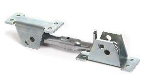
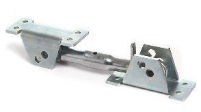
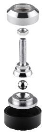
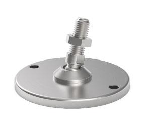
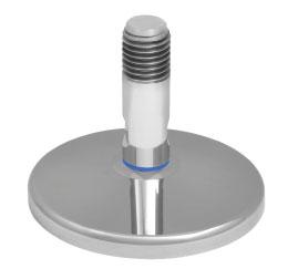
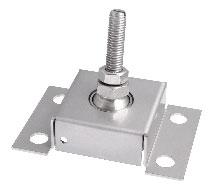
Self-centering adjustable feet feet
Adjustable upper plate upper upto5000kg
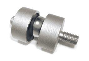

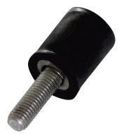
Accessory with ball upto5000kg
Compression
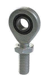
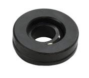
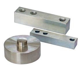
Ball-and-socket joint Ball-and-socket
upto112kN(dynamic) upto146kN(static)
Axial spherical plain bearings Axial
upto10000kg
Level measurements - false cellsupto100000kg
Up to 100000 kg application range
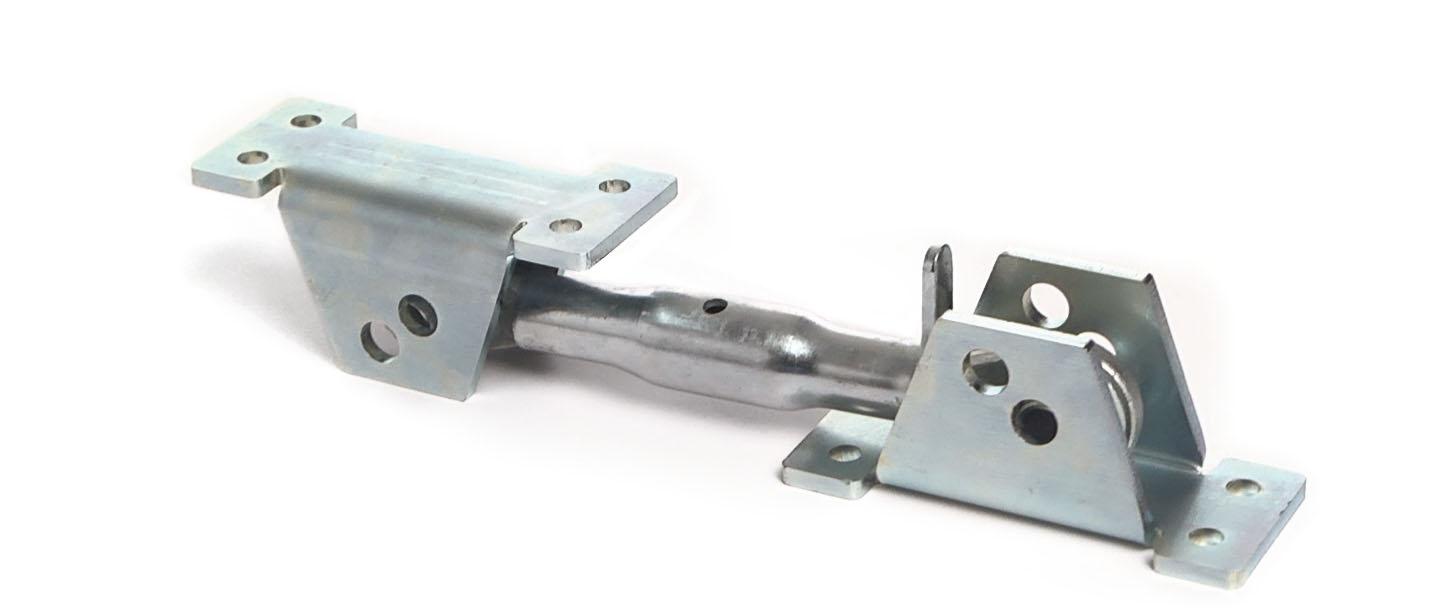
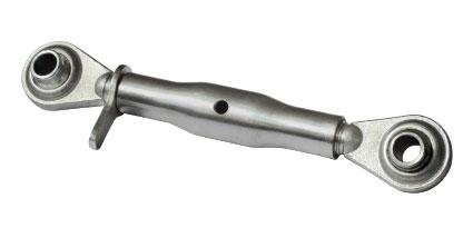

DIMENSIONS
DESCRIPTION
Galvanized steel turnbuckle with dual ball-and-socket.
Net weight:
Working load: Ultimate overload:
Galvanized steel anchor plate for TENDITORE300
Net weight:
DESCRIPTION
Suitable for static applications; place the constraints in a horizontal position. Turnbuckle lock for constraint adjustment.
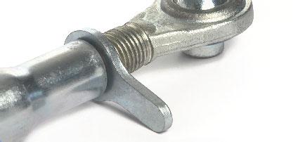
APPLICATION EXAMPLE: HOW TO MAKE MOUNTING KITS WITH HORIZONTAL CONSTRAINTS
By a copper wire, connect the upper supporting plate with the lower supporting plate, then link together the lower plates to the earthing system.
To ensure the stability of the structure, the system designer must predict any further precaution against side shifts and anti-tilt in function of: knocks and vibrations, wind effect, seismic conditions and hardness of support structure.
Application example with column load cells
Application example with compression load cells
1 Load cell.
2 Mounting kit for column load cell.
3 AISI 304 stainless steel upper and lower bases.
4 Threaded rod.
5 Nut to be used as jack.
6 Anti-tilt self-locking nut.
7 Washer.
8 Hole diameter 20 mm larger than the bolt.
Application example with V15000 - V30000 - V100000 mounting kits
STRUCTURE WITH 3-POINT SUPPORT
CONSTRAINTS PLACEMENT ON 3/4 SUPPORTS: the horizontal constraints can be positioned both on supports and on the four sides, centrally between two supports.
STRUCTURE WITH 4-POINT SUPPORT
Self-centering joint feet
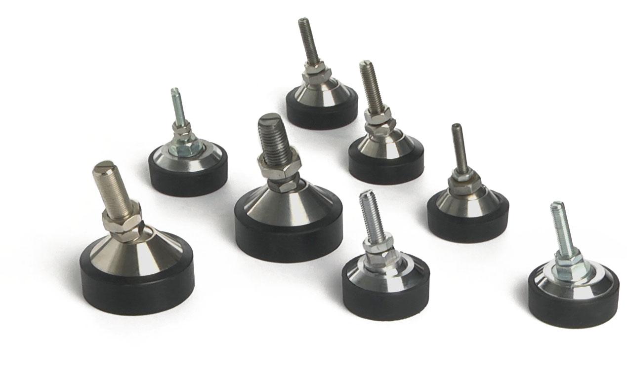
500 M8Ø60xH92mm0.3SB2
500 M10Ø60xH92mm0.3SB2
2000 M12Ø60xH92mm0.4SB2
5000 M20Ø80xH105mm0.9SB2
2000 M12Ø60xH78mm0.4PXC
2000 M12Ø62xH86mm0.4SB2
5000 M20Ø62xH110mm0.9SB2
2000 M12Ø60xH78mm0.4PXC
Self-centering joint feet
DIMENSIONS AND APPLICATION
SB2 -stainlesssteel
SB2 -stainlesssteel
SB2 -stainlesssteel
SB2 -stainlesssteel
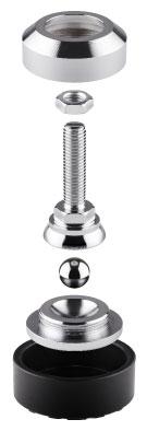
PXC -stainlesssteel/ galvanizedsteel
SB2 -galvanizedsteel
SB2 -galvanizedsteel
Ball-mounted self-centering pluggable feet
H 102 mm: for BENDING BEAM and SHEAR BEAM load cells
H 89 mm: for FLC load cells
Up to 10000 kg application range
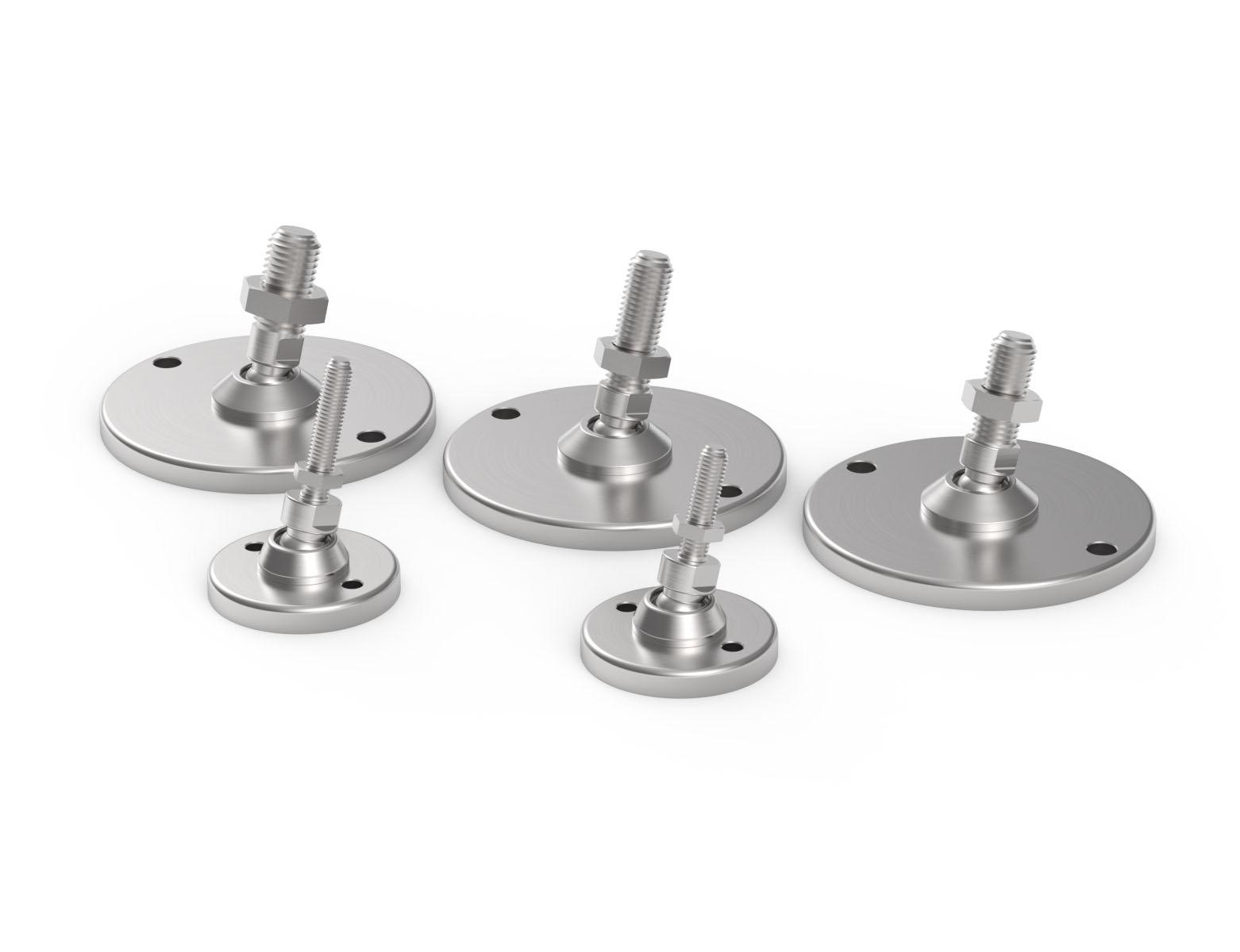
Ball-mounted self-centering pluggable feet
Self-centering adjustable hygienic feet
Up to 20000 kg application range
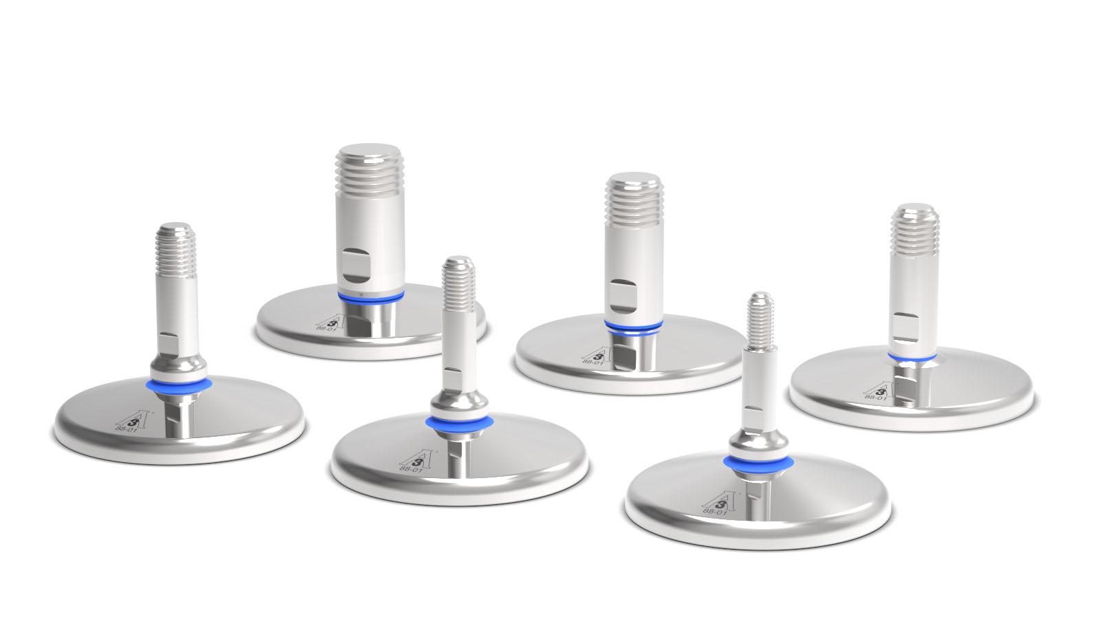
MAX STATIC LOAD
THREADDIMENSIONSMATERIALNET
On request: pluggable hygienic foot, with holes for fixing to the floor.
For other types of hygienic or customized feet, please contact https://martinlevelling.it
CERTIFICATIONS
Equivalent of the CE marking for the United Kingdom
American standard that regulates the design, production and use of hygienic equipment
Self-centering adjustable hygienic feet
DIMENSIONS AND APPLICATION
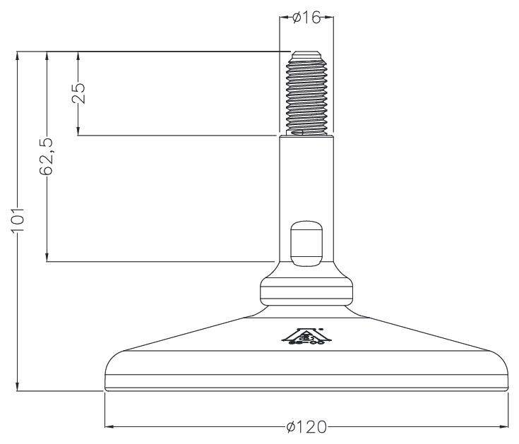
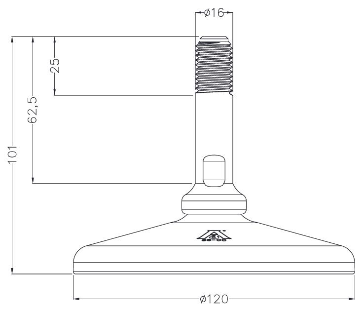
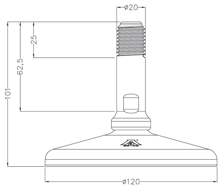
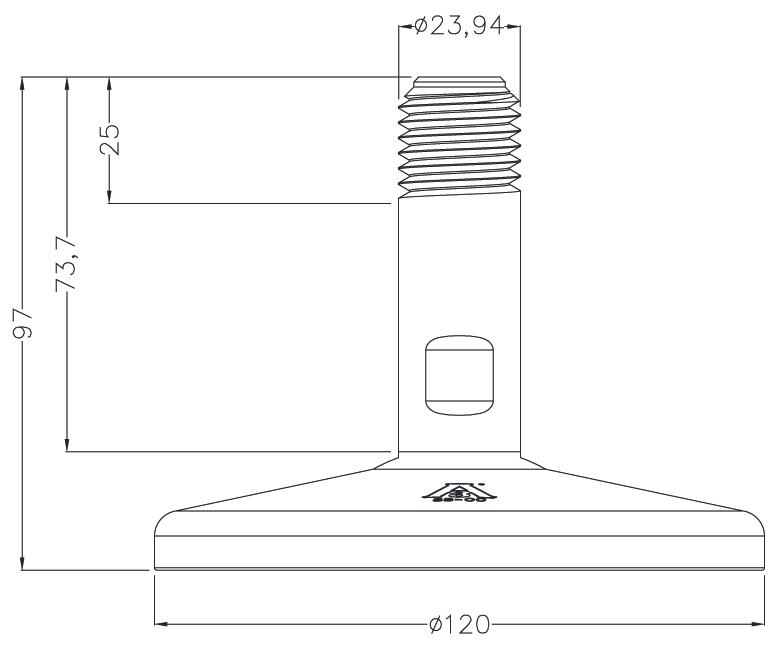
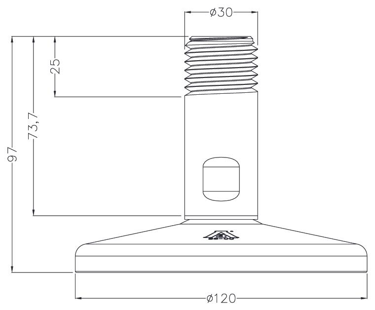
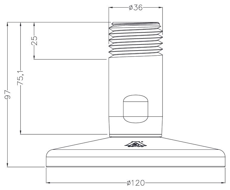
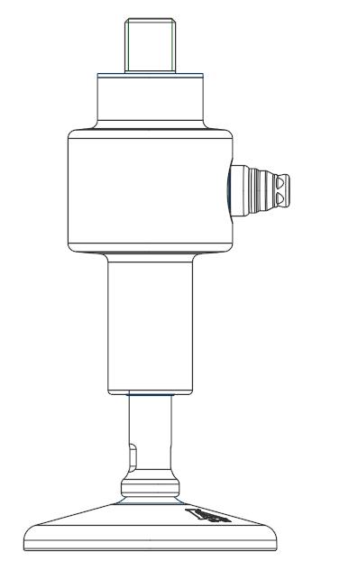
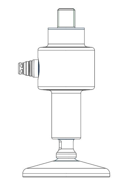
Adjustable upper plate
Plates for constraint against lateral forces and anti-tilt. For self-centering joint foot.
Up to 5000 kg application range
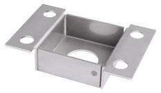
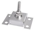
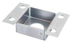
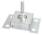
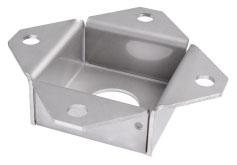
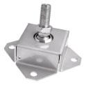
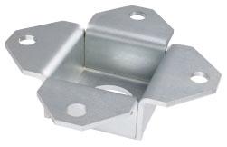
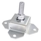
MAX STATIC LOAD
DIMENSIONS (mm)
steel
Up to 5000 kg application range
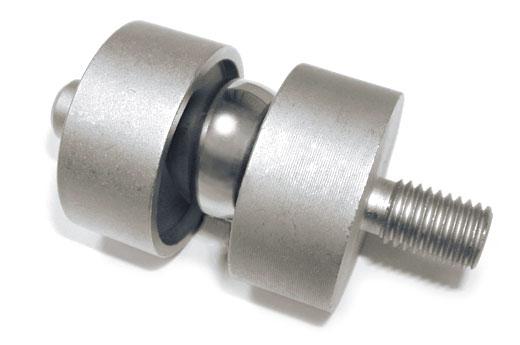
MAX STATIC LOADFOR LOAD CELLSNET WEIGHT (kg)
DIMENSIONS
2000 FTK - FT-P - FTKL FTZ - FTP - CLS M12x1.750.3
5000 FTK - FTKL - FTZ (5000 kg) FTP (3000-5000 kg) - CLS (5000 kg) M20x2.50.4
DIMENSIONS AND APPLICATION
DESCRIPTION
Stainless steel accessory with ball to compensate for misalignment of the support plates.
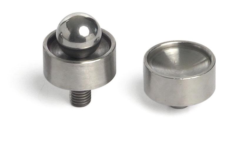
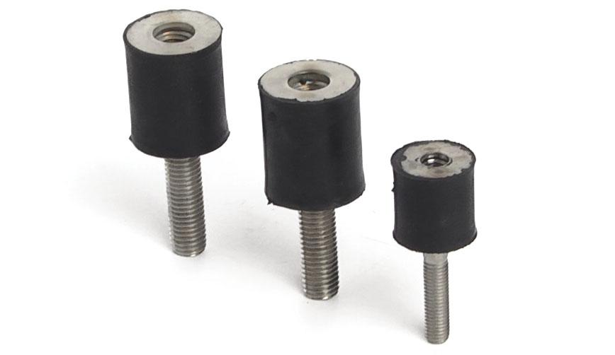
DIMENSIONS AND APPLICATION
The
EXAMPLE OF APPLICATION
WARNING! Tightenuntilitstopswithoutforcing,to avoiddamagingtherubber-coatedjoint.
Stainlesssteelandrubbercompressionjointsto compensateforanymisalignmentsofthesupportplates. Canbeusedforsystemswithatleast3supports.
Ball-and-socket joints with nut
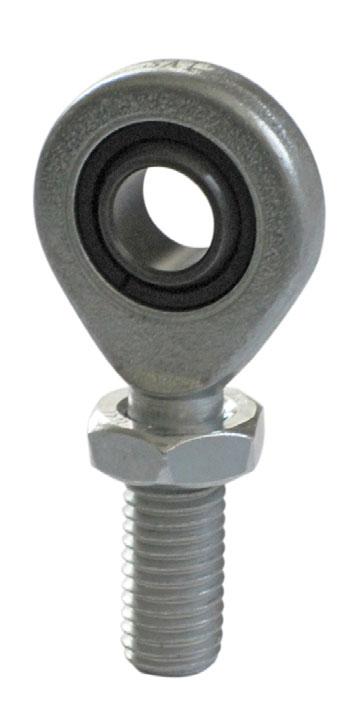
DIMENSIONS
Series load cells:
Up to 10000 kg application range
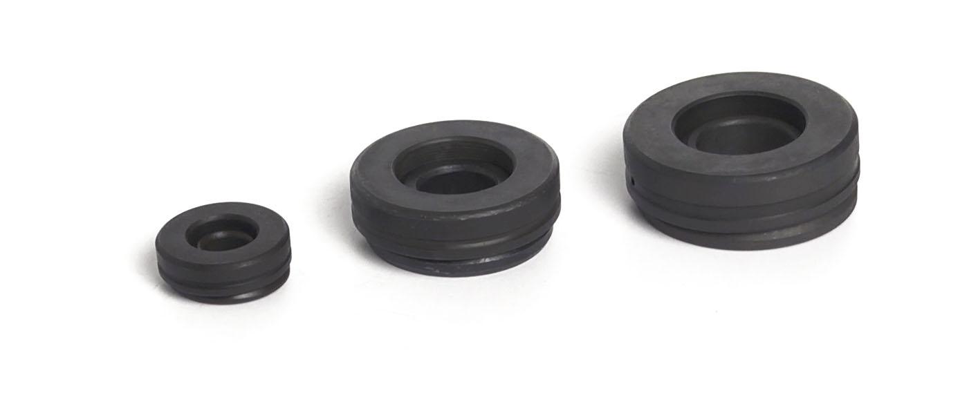
DESCRIPTION
Axial spherical plain bearing
5000
Kit composed by bearing, galvanized bolt (20x80 mm) and washer (22x60 mm).
CLS, FTK, FTKL, FTP, FT-P, FTZ 0.07SNODOGE12
CLS (5000 kg), FTK (3000-5000 kg), FTKL, FTZ (5000 kg), FTP (3000-5000 kg) 0.3SNODOGE20
10000 FTP 10000 kg 0.9SNODOGE25
Kit composed by bearing, galvanized bolt (24x100 mm) and washer (26x72 mm).
DIMENSIONS AND APPLICATION
DESCRIPTION
Hardened 100Cr6 steel bearing to compensate for misalignment of the support plates.
Up to 100000 kg application range
CAPACITY
BENDINGBEAM
SHEARBEAM
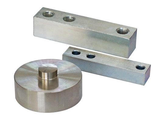
EQUIVALENT TO LOAD CELLS MATERIALNET WEIGHT (kg)
Galvanizedsteel
200 FCK(5-10kg)-FCOL(20-200kg)0.5
Galvanizedsteel
2000
5000
Galvanizedsteel
1500 FCAL(30-300kg)-FCAX(30-1500kg)0.6
FTP(75-2000kg)-FTK(75-2000kg) FTKL(500-2000kg)-FTZ(500-2000kg) FT-P(300-2000kg) 0.9
Galvanizedsteel
FTP(3000-5000kg)-FTK(3000-5000kg) FTKL(3000-5000kg)-FTZ(5000kg)1.6
COMPRESSION-LOWPROFILE
Stainlesssteel
DESCRIPTION
15000 CBL(250-12500kg)-CBX(15000kg)1.4
Stainlesssteel
100000 CBL(50000-100000kg)10.5 Level measurements - false cells
30000 CBL(15000kg)-CBX(30000kg)2.2
50000 CBL(30000kg)-CBX(50000kg)4
Structuralmechanicalsteelelementsthatcanbeusedin combinationwiththeloadcellsformeasuringthelevelofliquid orweighingpowderproductsthatdonotrequireahighdegree ofprecision.
Theydonottransmitanyelectricalsignals. Theycanbemountedonthesamemountingkitsastheloadcells.
Stainlesssteel
Stainlesssteel
Toenableuseofthefalsecells,itis absolutelynecessarythatthestructure toweighhasauniformshapeand isgeometricallydivisible.Itmustbe perfectlylevelandthetypeofproduct tobeweighedmustenablehorizontal positioning,asifitwerealiquid(otherwise, loadingsystemswhichdistributethe product/loaduniformlyarerequired).
Mountingkitsshouldbeusedforall supports(alsoforthosewithfalsecells), because,apartfromsimplifyingand optimisingcellassembly,theyenable futurereplacementoffalsecellswith realversions,accuracyandthereliability oftheweighingprocessneedstobe improved.
Theweightindicatorwillshowtheeffective weightmultiplyingthesignalbytwoor three,dependingontheapplication.
STRUCTURE WITH 3-POINT SUPPORT 1LOADCELL+2FALSECELLS
STRUCTURE WITH 4-POINT SUPPORT 2LOADCELLS+2FALSECELLS
C=SUPPORTFOOTWITHLOADCELL F=SUPPORTFOOTWITHFALSECELL
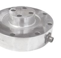
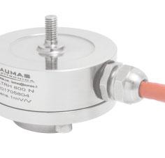
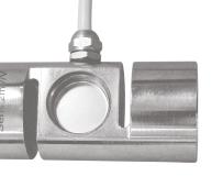
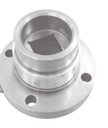
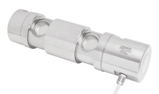
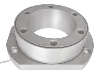
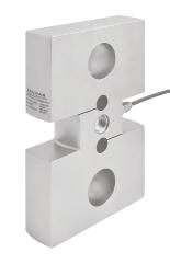
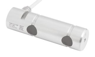
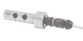
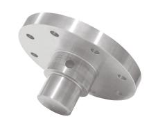
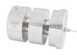
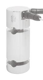
Production of load cells based on CUSTOMERS REQUESTS
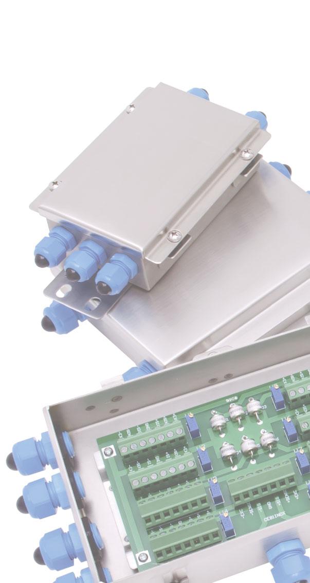
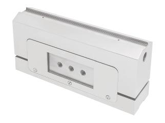
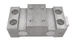
LAUMASdesignsandmanufactures“CUSTOM”loadcellstoofferthebest solutionstocustomerneeds.
Customizationsaredesignedtosolvespecificcustomerproblemsandmeet theneedsofparticularapplicationsinspecialconditions,evenforusein potentiallyexplosiveatmospheres(Atex-IECEx).
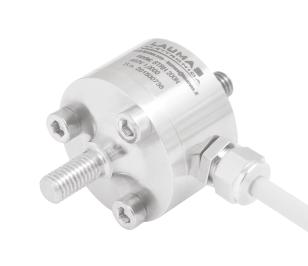
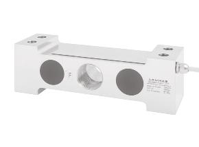
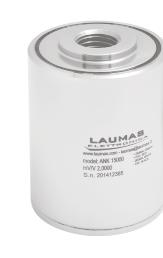
•Pre-amplifiedloadcells
•Biaxialandtriaxial
•TwostraingaugesWheatstonebridges
•Torquedetection
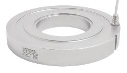
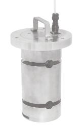
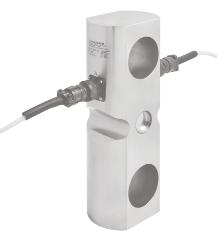
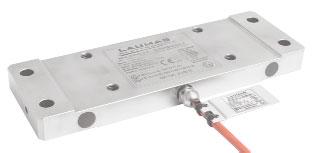
•Specialcableshigh/lowtemperaturewithnon-standardthermalcompensation
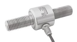
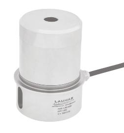
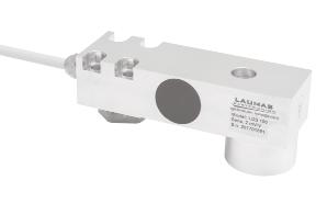
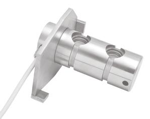

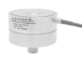
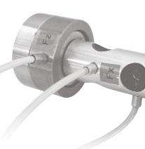
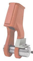
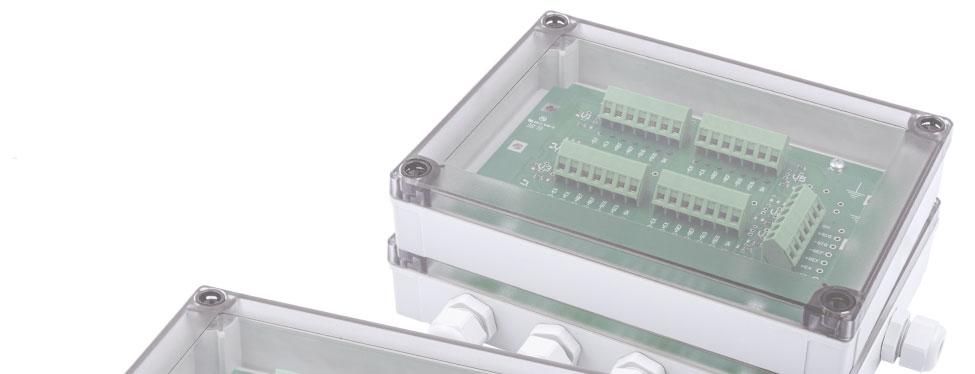


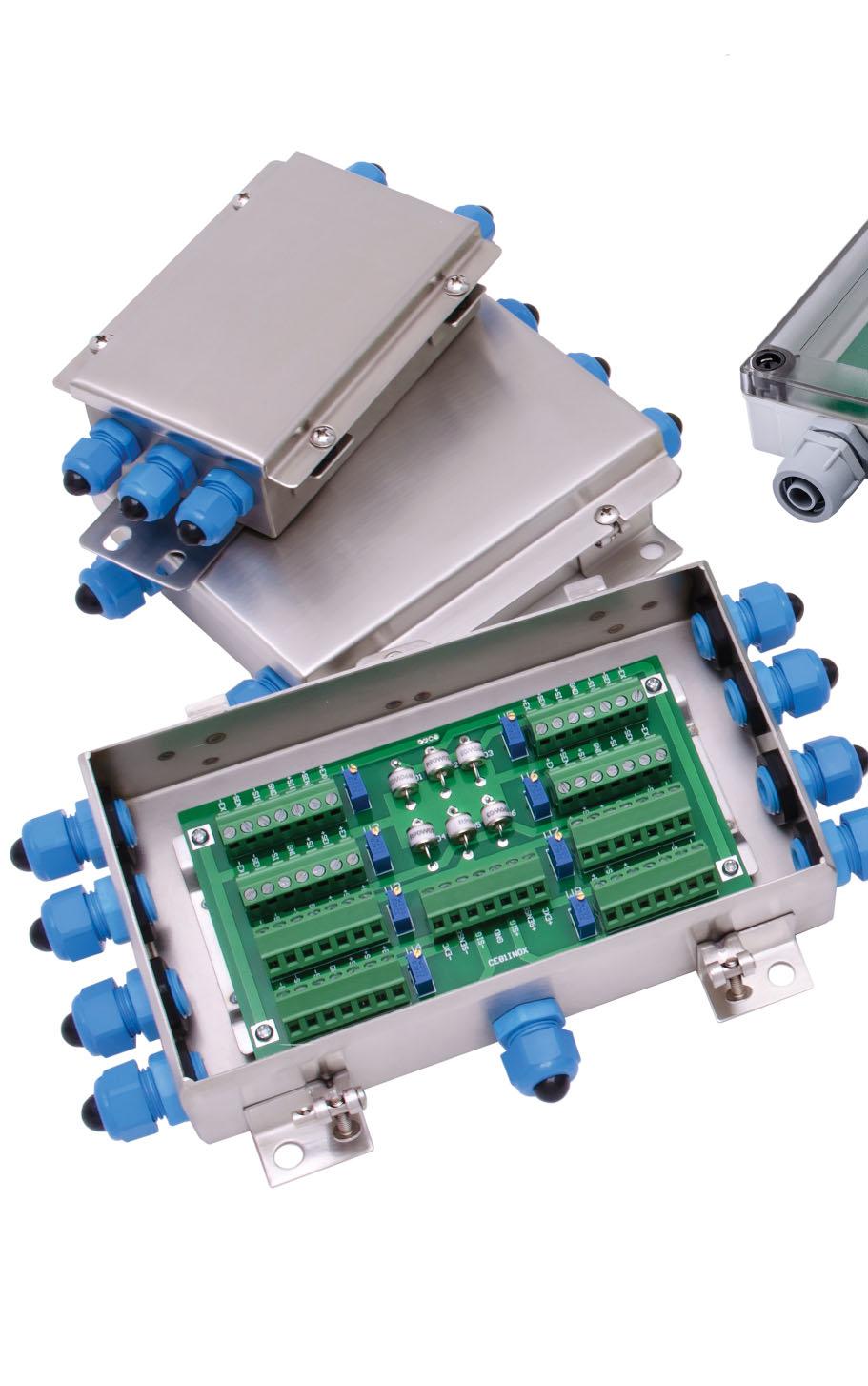
AISI304stainlesssteelorABSjunctionboxes,includingequalizationboards orparallelconnectionboards,toconnectfrom1to4orfrom5to8loadcells.
Lightningandelectricalshockprotectiondevice.
ATEXcertifiedversions:
II1GExiaIICT4-20°C ≤ Tamb+60°C
II1DExtaIIICT85°C-20°C ≤ Tamb+60°C
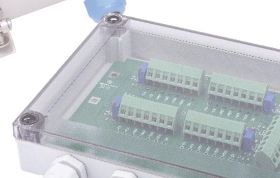
Hygienicversion:hygienicdeviceRPSCQCauthorizedby3-ASSI.
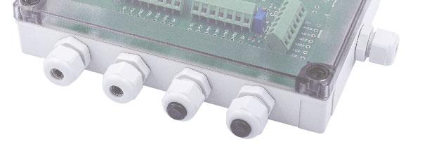
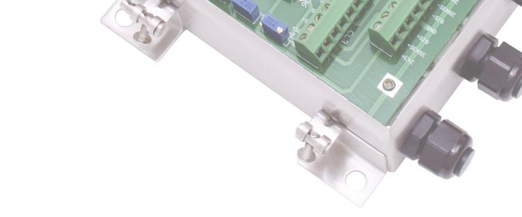
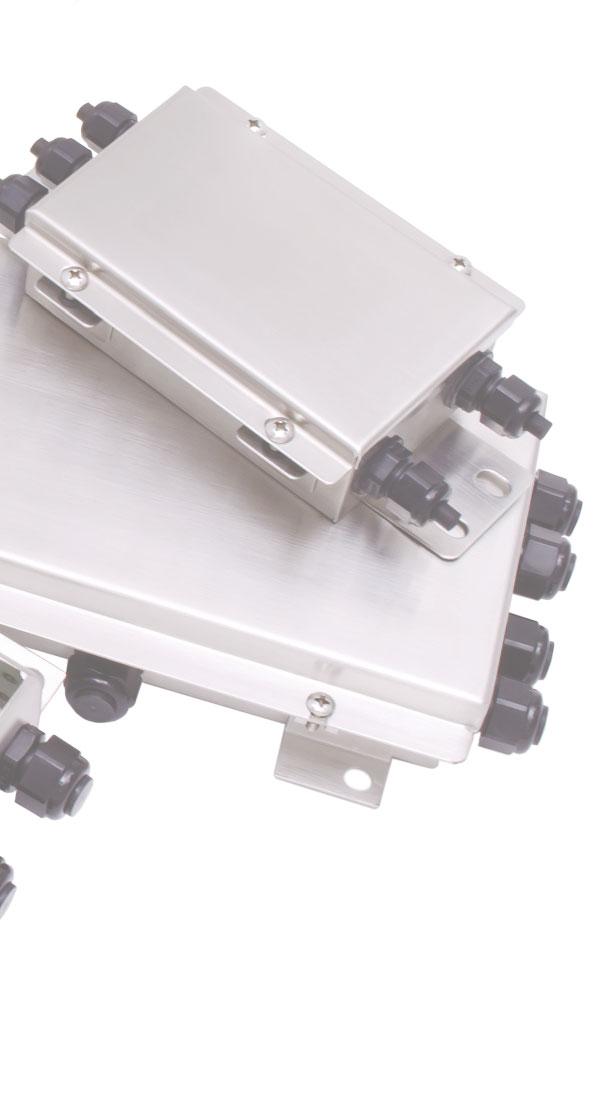
VIA I MAGGIO N. 6
43022
MONTECHIARUGOLO (PR) - ITALY
PHONE (+39) 0521 683124
FAX (+39) 0521 681091
EXPORT SALES DEPARTMENT: sales@laumas.it