
PRODUCT CATALOGUE
ABOUT CHEMITEC
WHO WE ARE
Founded in Florence, Italy in 1984, Chemitec is a world-class manufacturer of instruments, controllers and other solutions for modern, professional watermonitoring applications.
Chemitec operates in more than 80 countries and in 2015, we extended our international presence with the opening of our first Asian subsidiary in Shanghai, China.
WHAT WE DO
Drawing upon our vast experience and expertise in water treatment and liquid chemical analysis, Chemitec designs, manufactures and distributes sophisticated level and flow rate detection systems, analysers and sensors to industries worldwide, enabling them to take their processes to a new standard of operational excellence.
With a reputation for exceptional quality and service, we specialise in developing state-of-the-art, customised, user-friendly products for our discerning clients.
OUR VISION
TO LEAD THE WORLD IN HIGH-TECH ONLINE WATER & LIQUID ANALYSIS
Our aim is to be the world leader in online water and liquid analysis through new specific sensor development, ensuring an international presence, a customer-focused approach and a philosophy of continuous appraisal and improvement.
OUR MISSION
TO TURN KNOWLEDGE INTO INNOVATION
Everyone at Chemitec is driven by a single purpose - to translate our knowledge and expertise into new and innovative products that not only fulfill customer requirements but provide user-friendly, cost-effective, sustainable water-monitoring solutions.

2 CHEMITEC PRODUCT CATALOGUE
CUSTOMER SATISFACTION

Chemitec provides an experienced, professional and comprehensive technical consultancy service. We are focused on the individual needs of each customer, from the preliminary stages of the project through to design, manufacture and after-sales technical support.
SUSTAINABILITY
At Chemitec, we’re serious about sustainability and our responsibility towards environmental protection. We understand that positive actions we take today benefit both us and future generations.
That’s why, from recyclable packaging to innovative systems that reduce consumption of chemicals, water and energy, sustainability is at the heart of everything we do.
QUALITY ASSURANCE
As a quality-oriented company, Chemitec monitors and evaluates all aspects of design, planning (MRP), production (Kaizen) and after-sales support in order to guarantee customer satisfaction.
Chemitec develops its products according to the most rigorous international quality standards. We operate in accordance with quality management system UNI EN ISO 9001:2015, while our dedication to maintaining the highest standards in health and safety and environmental management is reflected in ISO 14001 and ISO 45001 certification respectively.
RESEARCH & DEVELOPMENT
With 40 years of R&D experience in the field, uncompromising quality and premium components, our highly skilled engineers develop all of our products in accordance with individual customer specifications, ensuring optimum performance and reliability at the right cost.
APPLICATIONS
INDUSTRY FIELDS
At Chemitec, almost 40 years of experience means we understand that every application is unique, with process requirements dependent on the individual needs and specification of the project.
Our extensive array of instruments, tailor-made solutions and services are based on a vast range of application parameters and measurement principles. This enables optimal adaptation to every challenge and environment and allows us to deliver superior water-monitoring solutions.
WASTEWATER
Dedicated monitoring solutions for improving wastewater treatment processes such as nutrient removal, aeration control, nitrification/denitrification and sludge dewatering.
DRINKING WATER
Chemitec solutions help operators monitor incoming water, manage changes to the treatment process, and maintain the correct dosages and adjustments to ensure the quality of the final effluent.
ALL APPLICATIONS
Chemitec’s comprehensive range of instruments includes multi-application solutions that help operators achieve reliable, repeatable results in every field.
INDUSTRIAL WATER
Chemitec's advanced water monitoring tools help operators in a wide range of industries meet the most demanding monitoring and process management needs.
FISH FARMING
Precise monitoring of turbidity, dissolved oxygen, electrical conductivity and other essential waterquality parameters in aquaculture facilities.
IRRIGATION
Chemitec’s advanced probes, sensors, controllers and analysis systems for agricultural irrigation applications help operators save money, improve yields and ensure greater product quality.
4 APPLICATIONS

ELECTROPLATING
In electroplating, where water bath temperature and chemical composition are crucial, Chemitec’s advanced instruments allow users to have complete confidence that their process is safe and effective.
CLEAN IN PLACE (CIP)
Advanced instruments for monitoring water parameters during the automated cleaning of pipes, vessels and equipment where the highest standards of hygiene must be achieved.
PULP & PAPER
Chemitec’s state-of-the-art instruments allow operators to reduce fresh water consumption while treating discharge water to comply with environmental regulations and protect local resources.
FOOD & BEVERAGE
Chemitec controllers, sensors and analysers help optimise food and beverage production processes and ensure products comply with safety legislation and shelf-life requirements.
COOLING TOWERS
Solutions for ensuring maximum uptime through preventative protection and superior service throughout the water and steam process.
CHEMICAL INDUSTRY
In the production of chemicals, where achieving delicate parameter balance is key to product quality, Chemitec is present with a comprehensive range of sophisticated instruments.
SAMPLERS
S480 UV NO3 • S480 UV SAC2 COLOUR/PAH 42 S480 Colour S480 UV PAH DISINFECTANTS 44 S494 S495 COMPACT PRO 46 Plug & play multiparameter portable unit OUR TEST 47 Measurement of OUR ANALYSIS & SAMPLING 49 Methods of measuring 4001 SERIES 50 Multiparameter photometric analyser for chlorine and other disinfectants/oxidant COLOR MASTER 52 Photometric colour analyser COLOR TEC 54 Photometric analyser for chemical parameters UV METER 56 Photometeric analyser UV254 • Nitrate UV • Hydrocarbon UV FILTRATION SYSTEM 60 SF 100 UF TEC SAMPLING SYSTEM 62 Fixed installation or portable use FIXED 63 SP5 S • SP5 B FIXED & SELF EMPTYING 64 SP5 A • TP5 W PORTABLE 65 TP5 C • P6 80 SERIES 12 Multiparametric plug & play control unit 70CT SERIES 14 Multiparametric controller for cooling towers 70DW SERIES 16 Multiparametric controller for drinking water treatment 50 SERIES 18 Multiparametric plug & play control unit 46 SERIES 20 Single or double channel control unit 30 SERIES 22 pH / ORP - conductivity control unit PH & ORP ELECTRODES 24 S401 • S406 • S408 range S401 DIG/N • S406 DIG/N S401 DIFF • S406 DIFF/N CONDUCTIVITY 28 S411 range S411 DIG
DIG/N INDUCTIVE CONDUCTIVITY 30
IND range
IND HT range S411 DIG IND range DISSOLVED OXYGEN 33 S423 C OPT TURBIDITY 34 S461 LT S461 TN S461 N SUSPENDED SOLIDS 37 S461 ST S461 S NUTRIENTS 39 S470/N S480 ANALYSERS PORTABLE UNITS
CONTROLLERS 6 CHEMITEC PRODUCT CATALOGUE CONTENTS
S411
S411
S411
SENSORS
PROCESS SOLUTIONS
ULTRASONIC 92 50 Series F/L Flow/Level controller S425 Ultrasonic level sensor METER compact ultrasonic level meter RADAR 95 RPL 55 RDR 81 RDR 75 SLUDGE INTERFACE 98 Echosmart HYDROSTATIC 100 KPL KWL PIEZORESISTIVE & CAPACITIVE 102 KPT • CPT SPT • SDT IMMERSION SENSOR HOLDER 106 S315 range Jointed support and installation INSERTION SENSOR HOLDER 108 S305 INS • S305/M BYPASS SENSOR HOLDER 109 PSS 8 PRESSURISED SENSOR HOLDER 110 PSS3 • SPP • SPPFIL PRE-ASSEMBLED PANELS 111 Paneltec Series DETECTOR 67 Sewer monitoring system OXYSMART 68 Optimisation system for
treatment plants Three local algorithms OXYSMART BLUE 70 Simplified biological process automation system CHEMITEC WEB 71 Remote management system OPEN CHANNEL WITH RESTRICTIONS 74 50 Series F/L Flow/Level controller S425 Ultrasonic level sensor Venturi • Weirs Palmer-Bowlus ELECTROMAGNETIC 78
C
biological
S103
converter
U0-D0 installation ULTRASONIC 86 S101 F • 200 H DOPPLER EFFECT 88 DFM 6.1 • PDFM 5.1 AREA X VELOCITY 90 AVFM 6.1 • STINGRAY WEB APP
PRESSURE FLOW METERS 7 CHEMITEC PRODUCT CATALOGUE
Selection table CH608 converter CH406
Overview of measuring tubes and insertion sensors CH2300 measuring tube
ACCESSORIES
LEVELS
SENSORS & CONTROLLERS

S401 • S406 • S408
DISSOLVED OXYGEN 33 S423 C OPT TURBIDITY 34 S461 LT S461 TN S461 N SUSPENDED SOLIDS 37 S461 ST S641 S NUTRIENTS 39 S470/N S480 S480 UV NO3 • S480 UV SAC2 COLOUR/PAH 42 S480 Colour S480 UV PAH DISINFECTANTS 44 S494 S495 PORTABLE UNITS COMPACT PRO 46 Plug & play multiparameter portable unit OUR TEST 47 Measurement of OUR CONTROLLERS 80 SERIES 12 Multiparametric plug & play control unit 70CT SERIES 14 Multiparametric controller for cooling towers 70DW SERIES 16 Multiparametric controller for drinking water treatment 50 SERIES 18 Multiparametric plug & play control unit 46 SERIES 20 Single or double channel control unit 30 SERIES 22 pH / ORP - Conductivity control unit SENSORS PH & ORP ELECTRODES 24
range
DIG/N
DIG/N S401 DIFF/N
DIFF/N CONDUCTIVITY 28 S411 range S411 DIG S411 DIG/N INDUCTIVE CONDUCTIVITY 30 S411 IND range S411 IND HT range S411 DIG IND range
S401
• S406
• S406
CONTROLLER/SENSOR CONNECTION TABLE
S401 DIG/N
S401 DIFF/N
S401 VG
S401 LC/S401 LC OSM
S401 VG C
S401 VG HTAJ
S408 MEC/POL PLUS
S406 DIG/N
S406 DIFF/N
Redox (ORP)
S406 POL/OXT
VG HTAJ
DIG
DIG/N
IND DIG
Conductivity
D12
C
Disinfectants
PAA
Oxygen Dissolved
S423C/OPT
S423/C/OPT/T
Turbidity S461 LT
Suspended Solids
Nutrients
Organic Substances/ Colour
9 CONTROLLER TABLE
30 Series 46 Series 50 Series 80 Series
Parameters Sensor models
pH
• •
• •
• • •+ •
• • •+ •
• • •+ •
• • •+ •
• • •+ •
• •
• •
• • •+ •
S406 VG
• • •+ •
• • •+ •
S406
S411
• • S411
• • S411
• • S411S • • •+ • S411/S411
• • •+ • S411
• •+ •
• • •+ •
• •+ •
•+ •+
S411 TEF C
S411 U/PS
S411 IND/S411 IND HT
S494
2 • •+ • S494
2 • •+ • S494
3 • •+ • S494
• •+ • S494
• •+ • S494
• •+ • S494
• •+ •
• •+ •
Cl
ClO
O
CLT
Br
H2O2
S494/CL2/HT70
• • •
• • •
• • •
• • S461
• • •
S461 N
TN
S461S • • • S461ST • •
4 + • • S470/N
3• • S470/NO
- NH4 + • •
S480
3 • • S480
254 • • S480
• •
• •
• •
S470/N NH
NO
3
NO
SAC
PAH
S480 Colour
S480 CHL
+ Through Digitiser
CONFIGURATION EXAMPLE
80 OR 50 SERIES UP TO 8 SENSORS
Here we have a graphical representation of an example controller configuration using either the 80 or 50 Series with digital sensors in a typical biological purification plant with two parallel treatment lines. The connection between the sensors in the field and the controllers can be cabled or wireless with radio modem antennas.

Data collected by the sensors is transmitted to the dedicated Chemitec Web platform that gives the operator remote access to live and stored measurements, alarm event setting and notification as well as configuration parameters modification.


10 CONTROLLERS
80 SERIES
50 SERIES
CHEMITEC WEB
WIRED OR WIRELESS CONNECTION
S401 DIFF/N S423 C OPT
S470/N
ST
S401 DIFF/N S423 C OPT
S470/N
ST
11 CONTROLLERS
S461
S461
80 SERIES
MULTIPARAMETRIC PLUG & PLAY CONTROL UNIT

Chemitec’s 80 Series delivers state-of-the-art control of industrial process applications, making it ideal for the modern water-treatment professional.
FEATURES
• Up to 12 parameters visible on the large display and saved in the internal data logger
• Stored data can be downloaded via USB or the controller's integrated Wi-Fi module
• Up to 8 mA outputs available with PID control for proportional dosing. 8 relays
• Modbus RS485 serial protocol ( Profibus on request)
• The large 7” touch screen RGB 800x480 colour display allows to display all parameters on a single screen
• Programmable analogue outputs for repeating measurements, PID control and temperature
• Digital output relays for set point adjustment
• Analogue input for perturbative functions or engineered display of additional measuring
• Digital input for disabling of dosage
MEASURES
• pH/ORP*
• Dissolved oxygen
• Conductivity*
• Turbidity
• Suspended solids
• Chlorine*
• Chlorine dioxide*
• Ozone*
• Chlorites*
• Hydrogen peroxide*
• Peracetic acid
• Nitrates (UV)
• Ammonia + Nitrate (ISE)
• Organic substances (UV)
• Colour (UV)
• Chlorophyll
• PAH/OIL (UV-Fluorescence)
* connectable to analogue sensors


12 CONTROLLERS
TECHNICAL SPECIFICATION
Display 7" TFT LCD graphic colour display 800x480 RGB with resistive touch 16:9
Languages Italian, English, French, German, Spanish
Data logger Internal Flash 64Mbit.
Download by USB port or Wi-Fi
Recording method Circular (F.I.F.O.) or filling
Display of stored data In tabular and graphical form with indication of maximum, minimum and average values of the period recorded Zoom function
PID control
Activation
Settable functions:
P [Proportional]; PI [Proportional – Integral] and PID [Proportional – Integral – Derivative]
On analogue or digital output
Proportional range 0...500%
Time
Integral and/or derivative 0:00...5:00 min
Analogue outputs Eight programmable; 0/4...20 mA; galvanic separation; opto-isolator 1KV; maximum load 500 Ohm; freely programmable output limits within the measuring ranges
Digital outputs Eight freely programmable; 1A 230V ON-OFF or PWM function
Alarm output
Alarm/wash
Digital inputs
NAMUR ; 3.6 mA [with range 4...20 mA ]
Two Alarm: instrument fault, minimum/maximum value, delay set point delay (live check); delay time; Set point disablement in case of alarm: Enable/Disable
Washing: programming of the interval (minimum 15 minutes) and of the duration from 00:00...24:00 hh:mm; during the washing phase they are frozen
Two for dosage disabling or washing cycle activation
Input voltage 24 Vdc/ac Absorption 10mA max
Serial outputs/ports Programmable RS485 for setup and remote real-time data or stored data download (through dedicated SW)
Baud rate 1200...38400
Manual commands Simulation of all analogue and digital outputs via keyboard
Power supply
90 - 240 Vac/dc 47 - 63 Hz
Transformer isolation 4 kV
Power consumption ≤ 20W
Electrical protection
EMI/RFI CEI-EN55011 - 05/99
Mounting Wall
Container Red ABS
Dimensions (WxHxD) 250x160x116 mm
Mechanical protection IP66
Weight 1 kg
Operating temperature 0...50°C
Humidity 10...95% non-condensing
Storage and transport -25...65°C
13 CONTROLLERS
70CT SERIES
MULTIPARAMETRIC CONTROLLER FOR COOLING TOWERS

Water-treatment professionals choose Chemitec’s 70CT Series controller for the monitoring and management of as many as eight parameters in cooling or evaporative towers where precision and repeatability are essential.
The system’s intelligent design and user-friendly interface simplifies measurement calibration and setting of dosing parameters. Meanwhile, in the absence of flow, a dedicated digital input immediately stops dosing and sends a signal via an alarm relay.
FEATURES
• 7" RGB 800x480 colour display
• Displays up to 8 measurements simultaneously
• Readings saved in internal data logger
• Stored data downloadable via integrated Wi-Fi module or USB.
• Up to 8 mA outputs available for proportional dosing
• Modbus RS485 serial protocol
• 8 relays
MEASURES
• Conductivity (digital sensor)
• Conductivity
• ORP
• pH
• Temperature
• Analogue input (4-20mA) freely programmable
14 CONTROLLERS
TECHNICAL SPECIFICATION
Display 7" TFT LCD graphic colour display 800x480 RGB with resistive touch 16:9
Languages Italian, English, French, German, Spanish
Data logger Internal Flash 64Mbit.
Download by USB port or Wi-Fi
Recording method Circular (F.I.F.O.) or filling
Display of stored data In tabular and graphical form with indication of maximum, minimum and average values of the period recorded Zoom function
PID control
Activation
Settable functions:
P [Proportional]; PI [Proportional – Integral] and PID [Proportional – Integral – Derivative]
On analogue or digital output
Proportional range 0...500%
Time
Integral and/or derivative 0:00...5:00 min
Analogue outputs Eight programmable; 0/4...20 mA; galvanic separation; opto-isolator 1KV; maximum load 500 Ohm; freely programmable output limits within the measuring ranges
Digital outputs Eight freely programmable; 1A 230V ON-OFF or PWM function
Alarm output
Alarm/wash
Digital inputs
NAMUR ; 3.6 mA [with range 4...20 mA ]
Two Alarm: instrument fault, minimum/maximum value, delay set point delay (live check); delay time; Set point disablement in case of alarm: Enable/Disable
Washing: programming of the interval (minimum 15 minutes) and of the duration from 00:00...24:00 hh:mm; during the washing phase they are frozen
Two for dosage disabling or washing cycle activation
Input voltage 24 Vdc/ac Absorption 10mA max
Serial outputs/ports Programmable RS485 for setup and remote real-time data or stored data download (through dedicated SW)
Baud rate 1200...38400
Manual commands Simulation of all analogue and digital outputs via keyboard
Power supply
90 - 240 Vac/dc 47 - 63 Hz
Transformer isolation 4 kV
Power consumption ≤ 20W
Electrical protection
EMI/RFI CEI-EN55011 - 05/99
Mounting Wall
Container Red ABS
Dimensions (WxHxD) 250x160x116 mm
Mechanical protection IP66
Weight 1 kg
Operating temperature 0...50°C
Humidity 10...95% non-condensing
Storage and transport -25...65°C
15 CONTROLLERS
70DW SERIES
MULTIPARAMETRIC CONTROLLER FOR DRINKING WATER TREATMENT

The 70DW Series is a cutting-edge controller offering simultaneous display of as many of eight measurements for the monitoring and management of primary and drinking water plants.
The 70DW Series’ intuitive interface simplifies measurement calibration and setting of dosing parameters and, in the absence of flow, a dedicated digital input immediately ceases dosing and sends a signal via an alarm relay.
FEATURES
• 7" RGB 800x480 colour display
• Displays up to 8 measurements simultaneously
• Readings saved in internal data logger
• Stored data downloadable via integrated Wi-Fi module or USB.
• Up to 8 mA outputs available for proportional dosing
• Modbus RS485 serial protocol
• 8 relays
MEASURES
• Conductivity
• Free chlorine
• Total chlorine
• ORP
• pH
• Temperature
• Turbidity
• Analogue input (4-20mA) freely programmable
16 CONTROLLERS
TECHNICAL SPECIFICATION
Display 7" TFT LCD graphic colour display 800x480 RGB with resistive touch 16:9
Languages Italian, English, French, German, Spanish
Data logger Internal Flash 64Mbit.
Download by USB port or Wi-Fi
Recording method Circular (F.I.F.O.) or filling
Display of stored data In tabular and graphical form with indication of maximum, minimum and average values of the period recorded Zoom function
PID control
Activation
Settable functions:
P [Proportional]; PI [Proportional – Integral] and PID [Proportional – Integral – Derivative]
On analogue or digital output
Proportional range 0...500%
Time
Integral and/or derivative 0:00...5:00 min
Analogue outputs Eight programmable; 0/4...20 mA; galvanic separation; opto-isolator 1KV; maximum load 500 Ohm; freely programmable output limits within the measuring ranges
Digital outputs Eight freely programmable; 1A 230V ON-OFF or PWM function
Alarm output
Alarm/wash
Digital inputs
NAMUR ; 3.6 mA [with range 4...20 mA ]
Two Alarm: instrument fault, minimum/maximum value, delay set point delay (live check); delay time; Set point disablement in case of alarm: Enable/Disable
Washing: programming of the interval (minimum 15 minutes) and of the duration from 00:00...24:00 hh:mm; during the washing phase they are frozen
Two for dosage disabling or washing cycle activation
Input voltage 24 Vdc/ac Absorption 10mA max
Serial outputs/ports Programmable RS485 for setup and remote real-time data or stored data download (through dedicated SW)
Baud rate 1200...38400
Manual commands Simulation of all analogue and digital outputs via keyboard
Power supply
90 - 240 Vac/dc 47 - 63 Hz
Transformer isolation 4 kV
Power consumption ≤ 20W
Electrical protection
EMI/RFI CEI-EN55011 - 05/99
Mounting Wall
Container Red ABS
Dimensions (WxHxD) 250x160x116 mm
Mechanical protection IP66
Weight 1 kg
Operating temperature 0...50°C
Humidity 10...95% non-condensing
Storage and transport -25...65°C
17 CONTROLLERS
50 SERIES
MULTIPARAMETRIC PLUG & PLAY CONTROL
UNIT

The flexible 50 Series is used worldwide for a broad range of applications in water treatment, with easyto-use software, automatic recognition of sensors and multiple configurations making it a popular choice among water-treatment operators.
Compatible with Chemitec digital sensors, the 50 Series is expandable to traditional electrodes/sensors through AD Series digitisers.
FEATURES
• Available in three configurations: Up to two, four and eight simultaneous measurements, freely selectable.
• Two RS485 serial ports: Sensor with RS485 digital interface and Modbus RTU protocol. Sensor opto-isolated for connection with local network communication devices.
• Real-time clock allows software to archive data chronologically to flash memory
• Internal data logger with 250,000-record capacity
MEASURES
• pH/ORP
• Dissolved oxygen
• Conductivity
• Turbidity
• Suspended solids
• Chlorine
• Chlorine dioxide
• Ozone
• Chlorites
• Hydrogen peroxide
• Peracetic acid
• Ammonia + Nitrates (ISE)
• Nitrates (UV)
• Organic substances (UV)
• Colour (UV)
• Chlorophyll
• PAH/OIL (UVFluorescence)
• Programmable analogue outputs for repeating measurements, PID control and temperature
• Digital output relays for set point adjustment
• Analogue input for perturbative functions or engineered display of additional measuring
• Digital input for disabling of dosage
18 CONTROLLERS
TECHNICAL SPECIFICATION
Display Graphic TFT colour LCD 480x272 (visible area 95x93)
Languages Italian, English, French, German, Spanish
Keypad 5 bubble keys
Data logger Internal Flash 32Mbit Download by USB port
Display of stored data In tabular and graphic form, with indication of maximum, minimum and average values of the selected period Zoom function
PID control Settable functions: P [Proportional]; PI [Proportional – Integral] and PID [Proportional – Integral – Derivative]
Activation On analogue or digital output
Analogue outputs Four programmable; 0/4...20 mA; Galvanic separation
Alarm output NAMUR; 2.4 mA [with range 4...20 mA ]
Digital outputs Six; 3A at 230Vac
Set point Four operating range setting (Hysteresis/direction)
Alarm/wash Two Alarm: Instrument failure, min/max value, set point delay, permanence time (live check); Delay time; Set point disabling (in case of alarm); Enable/Disable Wash; Programmable interval (minimum 15 minutes) and duration
Digital inputs (2) To disable dosing or activate wash cycle
Serial ports/outputs RS485 programmable for set-up and real time data acquisition from remote or download stored data (using dedicated SW)
Baud rate 1200…38400
Communication protocol Modbus RTU ; on request PROFIBUS DP SLAVE, ethernet, device net, Modbus TCP
Manual controls Keyboard can be used to simulate all analogue and digital outputs
Power supply 90...240 Vac/dc 47– 63 Hz [on request 24Vac/dc]
Power consumption < 6W
Electrical protection EMI / RFI CEI-EN55011 – 05/99
Mounting Wall
Housing material ABS
Dimensions (LxHxP) 144x144x122.5 mm
Mechanical protection IP 66
Weight 1 kg
Operating temperature 0...50°C
Humidity 10...95% non-condensing
Storage and transport -25...65°C
19 CONTROLLERS
46 SERIES
SINGLE OR DOUBLE-CHANNEL CONTROL UNIT

In advanced, high-end water treatment applications, professionals choose 46 Series controllers to benefit from exceptional ease of use and full programming autonomy within their process.
With a graphic display showing digital output status, washing cycle and alarms plus intuitive controls for instrument calibration and configuration, it’s never been easier to take control.
MEASURES
• pH / ORP (redox)
• Conductivity
• Chlorine
• Chlorine dioxide
• Ozone
• Hydrogen peroxide
• Peracetic acid
• Chlorites
• Bromine
• Dissolved oxygen
• Turbidity
• Suspended solids
• Flow
FEATURES
• IP65-rated ABS wall-mounted casing
• Two independent 4-20mA output with galvanic isolation
• Four independent relays, two set-points, remote alarm and backwashing sensor setting by software
• On/Off, timed and proportional (PWM) routine function setting
• Solid state relay (SSR) with Wi-Fi embedded module, two-frequency output signal and two set-points
APPLICATIONS
• Wastewater
• Drinking water
• Fish farming
• Electroplating
• Clean in place
• Food and beverage
• Pulp and paper
20 CONTROLLERS
TECHNICAL SPECIFICATION
POWER SUPPLY (VERSION 100...240 VAC)
Electrical requirements
Frequency
Power supply fuse
From 100 to 240 VAC ±10%, 8 W (note 1)
50 to 60 Hz
Fuse glass body 5x20 mm T1.25AL250V
Short circuit protection Active
POWER SUPPLY (VERSION 24...48 VDC)
Electrical requirements
Power supply fuse
From 24 to 48 Vdc, or 24Vac ±20%, 8 W (note 1)
Glass body 5x20 mm T1.25AL250V
Short circuit protection Active
Reverse polarity protection Active
RELAY OUTPUTS
RL1, RL2, RL3 and RL4
2-SPST mechanical 250 VAC/5A, 30 VCC/3 A
Relay RL1, RL2 configuration Load activation
Relay RL3, RL4 configuration Load activation, probe wash, alarm repetition
Cycle time
1 sec to 3600 sec
Delay time 1 sec to 3600 sec
Test mode ON, OFF
SSR OUTPUTS (SOLID STATE RELAYS)
SSR1 and SSR2
2-SPST 60 V, max 100 mA, Bidirectional, NPN, PNP
Resistance in ON state 5 ohm max
Leakage current in OFF state 1 uA max
SSR1 and SSR2 configuration Pulse output
Frequency range
0 to 400 pulse/min
Pulse duration 100 m/sec
Test mode
OUTPUTS 4-20 MA
Analogue output signals
0 to 400 pulse/min
2 outputs 4-20 mA, galvanically isolated from one another and from the power supply
Measure error ± 0.01 mA
Load max. 800 Ω
Error condition
NAMUR Alarm: OFF, 3.6 mA, 22 mA
Test mode 3 to 23 mA
DIGITAL INPUTS
REED digital input
COMMUNICATION PORTS
Input for dry contact 5 Vdc, max 6 mA
RS485 digital communication port Modbus server ASCII/RTU standard protocol
OUTPUT 24 VDC FOR DIGITAL PROBE
Voltage 24 Vdc ±5%, max. 250 mA (note 2)
Short circuit protection Self-resettable fuse
(note 1) Only instrument: 8W; instrument + 1 digital probe: 10,5W; instrument + 2 digital probes: 13,5W; (note 2) DO NOT exceed the maximum allowable current limit, risk of damaging the apparatus
21 CONTROLLERS
30 SERIES
p H / ORP - CONDUCTIVITY CONTROL UNIT
Chemitec combines state-of-the-art technology with our renowned ease of use to deliver the 30 Series professional water-treatment controller dedicated to pH/ORP and conductivity measurement
MEASURES
• pH/redox
• Conductivity
APPLICATIONS
• Wastewater
• Drinking water
• Electroplating
• Cooling towers
• Irrigation
FEATURES
• IP65-rated front panel for protection against dust and water jets
• Programming keyboard with 5 bubble keys for instrument calibration and configuration
• 128x128-pixel monochrome display shows digital output, wash cycle and alarm menu status
• Automatic temperature compensation
• Two digital outputs for set point, with programmable hysteresis, or for set point delay alarm
• 0/4...20mA analogue output galvanically separated, programmable within the measurement range
• One frequency output with proportional control; two relay outputs for alarms or electrode washing
22 CONTROLLERS
TECHNICAL SPECIFICATION
pH/ORP Specifications
Range pH 0.00 to 14.00 pH –2000 to 2000 mV
Resolution 0.01 1 mV
Accuracy ± 0.10 pH ± 5 mV
Input impedance > 1012
CONDUCTIVITY/RESISTANCE SPECIFICATIONS
Range with C 0.01 cm-1/K 100 sensor 0.005 µS/cm to 200 µS/cm (5 KΩx cm to 200 MΩx cm)
Range with C 0.10 cm-1/K 10 sensor 0.05 µS/cm to 2 mS/cm (500 Ωxcm to 20 MΩx cm) 0…100°C
Range with C 0.20 cm-1/K 5 sensor 0.1 µS/cm to 4 mS/cm (250 Ωx cm to 10 MΩx cm)
Range with C 1.00 cm-1/K 1 sensor 0.5 µS/cm to 20 mS/cm (50 Ωxcm to 2 MΩx cm)
Range with C 10.0 cm-1/K 0.1 sensor 5 µS/cm to 200 mS/cm (5 Ωxcm to 200 K Ωx cm)
Range with C 20.0 cm-1/K 0.5 sensor 10 µS/cm to 400 mS/cm (2,5 Ωxcm to 100 K Ωx cm)
Resolution cond/res 0.0001/0.001/0.01/0.1/1 (adjustable from menu)
Accuracy cond/res ± 5% on the measuring point
Maximum distance of the sensor up to 50 m (up to 164 ft)
TDS range
Pt100/Pt1000 specifications
TEMPERATURE INPUT
0.3 to 2.0 ppm/µS
0.005 µS/cm to 200 µS/cm (5 K Ωx cm to 200 M Ωx cm)
Pt100/Pt1000 detection Automatic
Temperature measure range
0.0...100°C (32...212°F)
Temperature resolution 0.1°C
Temperature accuracy ** ± 1.0°C (± 1.8°F)
CONTROL
Keyboard 5 tactile feedback keys
Display Graphic LCD 128x128 pixels, Transflective, Backlit
Relay Output: RL1 and RL2
SSR1 Outputs (solid state relays)
2-SPST mechanical 250 VAC/5A, 30 VCC/3 A
2-SPST 60 VAC, max 100 mA, Bidirectional, NPN, PNP
SSRI frequency range 0 to 400 imp/min
SSRI pulse duration 100 m/sec
OUTPUTS 4÷20 MA
Analogue output signals 1 output 4÷20 mA, galvanically isolated from the power supply
Load Max. 500 Ω
DIGITAL INPUTS
REED digital input
Input for dry contact 5 VCC Max 6mA
Power supply: electrical requirements 24, 115 or 230 VAC, 2.5VA
Frequency 50 or 60 Hz
Power supply fuse
500 mA delay not recoverable
23 CONTROLLERS
pH ORP
S401 • S406 • S408
SERIES OF PH & ORP ELECTRODES
GENERAL FEATURES
The electrodes listed below are all of the combined type (measurement+reference), without maintenance, and are classified by their construction features, which makes them adaptable to multiple applications.
p H MODELS & APPLICATIONS
S401 VG
For general use
S401 VG HTAJ
For applications in liquids with a high content of suspended solids
S401 LC
For waters with low electrical conductivity
S401 LC OSM
For osmotised waters with very low electrical conductivity
S408 MEC
For high temperature liquids and/or installations under pressure
TECHNICAL SPECIFICATION
ORP MODELS & APPLICATIONS
S406 VG
For general use
S406 POL
For harsh chemical applications
S406 OXT
For high temperature liquids and/or installations under pressure
S406 VG HTAJ
For applications in liquids with a high content of suspended solids
AD SERIES DIGITISER
The AD Series Chemitec digitisers convert the signals of the common pH and ORP electrodes into serial signal with standard Modbus RTU protocol, allowing connection to the 80 and 50 Series plug & play multiparametric instrument.
24 SENSORS
Models S401 VG S408 MEC S401 LC OSM S401 LC S401 VG HTAJ S406 VG S406 POL S406 OXT S406VG HTAJ Measuring range 0...14 pH 0...14 pH 0...14 pH 2...14 pH 0...14 pH ±2000 mV ±2000 mV ±2000 mV ±2000 mV Operating temperature 0...80°C 0...130°C 0...100°C 0...60°C -5...135°C 0...80°C 0...130°C 0...130°C -5...135°C Maximum pressure 6 bar 16 bar 6 bar 16 bar 10 bar 6 bar 16 bar 16 bar 10 bar Min. liquid conductivity 5 µS/cm 50 µS/cm 0.1 µS/cm 2 µS/cm 50 µS/cm 5 µS/cm 2 µS/cm 50 µS/cm 50 µS/cm
S401 DIG/N • S406 DIG/N
DIGITAL PH AND ORP
SENSORS

FEATURES
• Teflon® porous septum’s liquid junction resists encrustations and chemical attack
• Reference electrode’s double junction increases service life in applications containing sulphides (H2S) and metals such as lead, mercury and silver
• New solid-state electrolyte allows a constant reference potential over time even during pressure and temperature variations
• Pt100 capillary temperature sensor is positioned behind sensitive membrane (pH or ORP) for accurate temperature measurement and compensation
• IP68 rated for protection of high-impedance electrodes from condensation
TECHNICAL SPECIFICATION
Models
S401 DIG/N
APPLICATIONS
• Drinking water
• Process water
• Wastewater
• Samples containing sulphides and metals such as mercury, lead and silver
S406 DIG/N
Measurement range 0...14 pH -1500 mV...+1500 mV
Measurement method
Accuracy
Potentiostatic
0.05 pH
± 5 mV
Repeatability ± 0.05 pH ± 1 mV
Response time
Operating temperature
Maximum operating pressure
Body material
Measuring electrode
Other materials
Mechanical protection
Power supply
Absorption
T90 < 60s
0...100°C in insertion / by-pass - 0...50°C in immersion
11 bar
Glass and PPS
Hemispherical glass membrane
Teflon®
IP68 sensor + cable
12...24Vdc
Max. 1W
Cable 10 m integral with the sensor (others on request)
Signal interface
Standard Modbus RTU protocol
25 SENSORS
S401 DIFF/N • S406 DIFF/N
DIFFERENTIAL DIGITAL PH AND ORP SENSORS

FEATURES
• Extensive lifespan
• Ryton® body
• Reference electrode with salt bridge and KCL reserve guarantees high stability of reference signal
• Operates in varying environmental conditions
• The measurement and reference electrode are connected to a ground reference for excellent measurement accuracy even in extreme conditions
• Replaceable reference electrode
TECHNICAL SPECIFICATION
Models
S401 DIFF/N
APPLICATIONS
• Heavy-duty processes
• Entry and exit from biological wastewater treatment
• Aggressive industrial applications
S406 DIFF/N
Measuring range 0...14 pH -1500...+1500 mV
Measurement methods
Potentiostatic differential
Accuracy ± 0.01 pH ± 5 mV
Response time T90 < 60s
Operating temperature
Immersion: -5...70°C (21...158°F) Insertion: -5...95°C (21...203°F)
Maximum operating pressure 6.9 bar (100 psig)
Body material
Measuring electrode
Other materials
Mechanical protection
Power supply
Absorption
Cable
Signal interface
Ryton®
Hemispherical glass membrane Platinum wire
PVDF, ceramic junction, Viton® o-rings, titanium (ground ref)
IP68 sensor + cable
12...24Vdc
Max. 1W
PUR, integral with the sensor, 10m
Standard Modbus RTU protocol
26 SENSORS
S411
SERIES OF CONDUCTIVE MEASURING CELLS

GENERAL FEATURES
Wide range of conductive cells designed for both water treatment and industrial applications. Courtesy of premium materials and cell constant (k), users can cover a wide range of applications with different measuring ranges.
APPLICATIONS
• Raw water
• Drinking water
MODELS
• S411 U
• S411 PS
• S411 D12
• S411/ S411 C
• S411 TEF/ S411 TEF C
TECHNICAL SPECIFICATION
27 SENSORS
Models S411/S411 C S411 TEF/ S411 TEF C S411 D12 S411 U S411 PS Constant K 1 1 1 1 10/100 Measurement range 0...50.000 µS 0...10.000 µS 0...200.000uS 0...50.000 µS 00...1.000/ 0.04...20.00uS Temp
Operating temperature 0...100°C 0...100°C 0...60°C 0...120°C 0...130°C Maximum operating pressure 5 bar 2 bar 1 bar 6 bar at 20° 16 bar Body material PP PTFE Epoxy PSU Stainless-steel Electrode material Graphite INOX Platinum Graphite Stainless-steel Process connection ½” GAS 1” GAS PG 13.5 ½” npt ½” npt
compensation No/Yes (C) No/Yes (C) Yes Yes Yes
S411 DIG
DIGITAL CONDUCTIVITY SENSOR FOR IMMERSION

FEATURES
• Reliable conductivity measurement courtesy of graphite electrodes
• Two-electrode conductive measurement method with temperature compensation
• Sensor body in PVC
• No mechanical moving parts
• Immediate installation and easy maintenance
• Modbus RTU serial communication protocol
TECHNICAL SPECIFICATION
Measurement range
Measurement method
Accuracy
Response time
APPLICATIONS
• Artesian wells
• Pure and process water
• Raw water
• Drinking water
• Process water
• Water from air conditioning and boiler systems
0...20000 µS
Two-electrode conductive
± 2.5% f.s.
90% of the value in less than 60 seconds
Refresh time 1 Secs
Temp compensation
Operating temperature
Maximum operating pressure
Body material
Electrode
Mechanical protection
Power supply
Absorption
Cable
Equipotential contact
With internal NTC sensor (external NTC sensor on request)
0...50°C
10 bar
PVC
Graphite
IP68 sensor & cable. The sensor is completely resin-coated inside
12...24Vdc
Max. 2W
10 m integral-10 m disconnectable cable
For solution included
Signal interface RS485 with Modbus RTU protocol
28 SENSORS
S411 DIG/N
WIDE RANGE DIGITAL CONDUCTIVITY SENSOR

FEATURES
• Broad measurement range courtesy of 4-electrode graphite sensor
• Measurement communication via Modbus RTU protocol
• Immediate installation and easy maintenance
• Integrated temperature sensor
• Sensor body in PPS and epoxy
• Electrodes in graphite
• No mechanical moving parts
• Maximum operating pressure: 5 bar
TECHNICAL SPECIFICATION
Measurement range
Measurement method
Accuracy
Repeatability
APPLICATIONS
• Pure and process water
• Wastewater
• Cooling towers
• Industrial and recirculating water
1 µS/cm - 200 mS/cm (k = 0.55 nominal)
Conductive with 4 graphite electrodes
≤ 4% on the reading point
≤ 0.2% on the reading point
Response time 5s
Operating temperature
-5...80°C in non-frozen waters
Maximum operating pressure 5 bar
Body material
Measuring electrode
Other materials
Mechanical protection
Power supply
Absorption
Cable
Signal interface
Epoxy and PPS
Graphite
Viton® O-rings
IP68
12...24 Vdc
<250 mA
10 mt
RS485 Modbus RTU protocol
29 SENSORS
S411 IND
SERIES OF INDUCTIVE CONDUCTIVITY CELLS

FEATURES
• Contactless measuring system
• Virtually maintenance free
• Re-calibration only required occasionally
• High tolerance to sensor “coating” phenomenon
AD SERIES DIGITISER
The AD Series Chemitec digitisers convert the signals of the inductive conductivity cells into serial signal with standard Modbus RTU protocol, allowing the connection to the 80 and 50 Series plug & play multiparametric instrument.
APPLICATIONS
• Polluted surface water
• Process monitoring
• Wastewater
• Highly contaminated or aggressive media
MODELS
S411 IND sensor only
S411 IND T by immersion
S411 IND E for insertion with T-fitting
S411 IND T INS for direct insertion on a flat wall
TECHNICAL SPECIFICATION
Operating temperature - 5...60°C (without freezing)
Measurement range 1000 uS...1000 mS
Temp compensation 2-wire Pt1000 temperature sensor
Cable Standard 5 metres
Operating pressure
Vacuum to 6.5 bar (100 psi)
Materials PVC with Viton® seals
Materials in contact
Immersion length
Assembly
Connection
Mechanical protection
Glass-filled polypropylene
600 or 1200 mm
Standard bracket or optional flange
0.5" BSP male
IP68
30 SENSORS
S411 IND HT
SERIES OF INDUCTIVE CONDUCTIVITY CELLS FOR HIGH TEMPERATURES/PRESSURES

FEATURES
• Manufactured in PEEK™, a food-grade material with excellent aggressive chemical resistance and high temperature performance
• Operates at 100°C continuously, withstanding thermal shocks commonly associated with CIP applications
• The sensors can be sterilised at up to 135°C
• Wide range of process connections
AD SERIES DIGITISER
The AD Series Chemitec digitisers convert the signals of the inductive conductivity cells into serial signal with standard Modbus RTU protocol, allowing connection to the 80 and 50 Series plug & play multiparametric instrument.
TECHNICAL SPECIFICATION
Operating temperature
Measuring range
Temp. compensation
APPLICATIONS
• Food and beverage
• Conductivity and concentration measurement
MODELS
S411 IND HT for insertion
S411 IND HT 60/120 for immersion
S411 IND HT TP for bypass with PVC T-fitting
S411 IND HT TS for bypass with SS T-fitting
- 5...100°C – up to 135°C for short periods (CIP process)
1000 uS...1000 mS
Temperature sensor Pt1000 with 2 wires
Cable 5 metres (disconnectable)
Operating pressure
Vacuum to 10 bar (150 psi)
Materials PEEK/AISI
Contact materials
Immersion length
Mounting
Connections
Mechanical protection
Body in PEEK – Temperature sensor in INOX (PEEK on request)
600 or 1200 mm
Standard bracket or optional flange
RJT 2”, 2.5”, 3” – Tri clamp 2”, 3” – IDF/ISS 2”, 2.5”, 3”
DIN 1185: 50 mm, 80 mm (other on request)
IP67
31 SENSORS
S411 DIG IND
DIGITAL INDUCTIVE CONDUCTIVITY SENSOR

FEATURES
• Operates in dirty water conditions up to 1 siemens
• Easily interfaced with data acquisition systems courtesy of Modbus RTU RS485 protocol
• Presence of four possible scales with one or two-point calibration
• Robust body in loaded PP
• Immediate installation
APPLICATIONS
• Wastewater
• Primary waters
• Cooling towers
TECHNICAL SPECIFICATION
Measurement range
0,5...1.000 mS/cm
Accuracy ± 6% on the measuring point
Repeatability ± 3%
Response time
T90 <60s
Operating temperature -10...60°C
Operating pressure
Body material
Mechanical protection
From vacuum to 6.5 bar
Glass-filled PP, PPS, Viton® O-ring
IP68 (Sensor & cable) / IP67 Connector
Power supply 12-24 Vdc
Cable 10 mt
Signal interface
RS485 Modbus RTU protocol
Thread 1” 1/2 GAS BSP
Measurement method
Inductive without contact electrodes
Temperature compensation Automatic with built-in PT1000
Salinity 0-120g/kg (programmable conversion factor default 0,64)
32 SENSORS
S423 C OPT
DIGITAL DISSOLVED OXYGEN SENSOR

FEATURES
• Reliable, accurate measurements with no drift removes need for calibration
• Minimal maintenance
• Does not consume oxygen, making it compatible with a variety of applications
• Suitable for applications in which the measuring liquid is almost stationary
• Available with titanium body for salt-water applications
TECHNICAL SPECIFICATION
Measuring range
Measuring method
APPLICATIONS
• Surface waters
• Wastewater
• Fish farming
0...20 mg/l
Optical measure by luminescence
Accuracy ± 0,2 mg/l when < 5mg/L ± 0,3 mg/l when > 5mg/L
Response
T90 < 60s
Refresh time < 1s
Temp. compensation
Operating temperature
With internal NTC sensor
0...50°C
Maximum operating pressure 5 bar
Body material
O-Rings
Mechanical protection
Power supply
Power consumption
Cable
Signal interface
SS316 (PVC or titanium optional)
NBR and silicon
IP68 sensor + cable
12...24Vdc
Max. 2W
10 m integral with the sensor
RS 485 Modbus RTU protocol
33 SENSORS
S461 LT
DIGITAL TURBIDITY SENSOR FOR LOW CONCENTRATIONS

FEATURES
• Measurement performed by 90° scattered light method compliant with ISO 7027 / EN 27027
• Immersion, insertion or bypass installation
• Stainless-steel body on request
APPLICATIONS
• Drinking water
• Industrial process water
• Low-turbidity waters
MODELS
• S461 LT (immersion)
• S461 LT INS (insertion in combination with S305-INS)
TECHNICAL SPECIFICATION
Measuring range
Measuring method
Resolution
Accuracy
Repeatability
Response time
Operating temperature
Maximum operating pressure
Body material
0...10 NTU / 0...100 NTU
90° Scattered light
0,01 NTU for 0...10 NTU range
0,1 NTU for 0...100 NTU range
≤ 5% of the measured value without calibration
≤ 1% of the measured value with calibration
±0.05 NTU for 0...10 NTU range
±0.5 NTU for 0...100 NTU range
T90 < 60s
0...40°C
4 bar
Black PVC (on request Stainless-steel )
O-ring Viton® and silicone
Optics
Mechanical protection
Power supply
Power consumption
Cable
Special glass with oleophobic treatment
IP68 sensor and cable
12...24Vdc
Max. 3W
10 mt integral with the sensor
Calibration 1-point and/or 2-point for scale
Signal interface Modbus RTU standard protocol RS485
34 SENSORS
S461 TN
DIGITAL TURBIDITY SENSOR FOR HIGH CONCENTRATIONS

FEATURES
• Measurement performed by 90° scattered light method compliant with ISO 7027 / EN 27027
• Immersion, insertion or bypass installation
• Stainless-steel body on request
APPLICATIONS
• Untreated water
• Surface water
• Process water
• Industrial or municipal water
MODELS
• S461 TN (immersion)
• S461 TN INS (insertion in combination with S305-INS)
TECHNICAL SPECIFICATION
Measuring range
Measuring method
Resolution
Accuracy
Repeatability
Response time
Operating temperature
Maximum
Body material
O-ring
Optics
Mechanical protection
Power supply
Power consumption
Cable
Signal interface
0...1000 NTU / 0...4000 NTU
90° scattered light
1 NTU for 0...1000 NTU range
1 NTU for 0...4000 NTU range
±2% for 0...1000 NTU range
±5% for 0...4000 NTU range
±5 NTU for 0...1000 NTU range
±20 NTU for 0...4000 NTU range
T90 < 60s
0...40°C
4 bar
Black PVC (stainless-steel on request)
Viton® and silicone
Special glass with oleophobic treatment
IP68 sensor and cable
12...24Vdc
Max. 3W
10 mt integral with the sensor
Modbus RTU standard protocol RS485
35 SENSORS
S461 N
NEPHELOMETRIC TURBIDITY CELL
CONTACTLESS, DIGITAL
FEATURES
• Contact-free measurement

• 90° scattering method compliant with ISO 7027/ EN 27027 with visible light beam
• Black rigid PVC sensor body
• Optional air bubble elimination device (de-bubbler)
• No mechanical moving parts
• Measurement pre-processed in the sensor, providing high sensitivity in low-signal transmission

APPLICATIONS
• Primary water upstream of treatment plants
• Industrial or municipal water
TECHNICAL SPECIFICATION
Measuring ranges
Measuring method
Resolution
0...100 NTU / 0...1000 NTU (optional 0...4000 NTU)
Nephelometric
0.1NTU for 0...100 NTU range
1 NTU for 0...1000 NTU range
Accuracy ±10% f.s
Maximum flow rate 60 l/h
Operating temperature
Maximum operating pressure
Materials
0...50°C
0.5 bar
ABS case
Black PVC measuring cell, receiver assembly and spotlight assembly
O-ring NBR and Silicone
Power supply
Power consumption
24Vdc
Max. 5W
Cable 10 m with connector
Signal interface
Modbus RTU standard protocol RS485
36 SENSORS
S461 ST
DIGITAL TURBIDITY AND SUSPENDED SOLIDS SENSOR

FEATURES
• Utilises dual sensor scattering measurement method
• Infrared optical measurement process delivers reliable concentration measurement
• Sensor body in AISI316
• No mechanical moving parts
• Pre-processed measurement in the sensor provides high sensitivity in low signal transmission
• Immediate installation and simple maintenance
TECHNICAL SPECIFICATION
Measurement range
Measurement method
APPLICATIONS
• Industrial and process waters up to 300 g/l (depending on sludge type)
• Biological purification processes
• Extraction processes including quarries, tunnels and aggregate extraction
MODELS
• S461 ST (immersion)
• S461 ST INS (insertion in combination with S305-INS)
• S461 ST/US with ultrasonic cleaning
• S461 ST/US INS with ultrasonic cleaning (insertion in combination with S305-INS)
Measuring ranges SS: 0-300 g/l depending on the type of sludge
Turbidity measuring ranges: 0...4000 NTU
Double-angle scattering light
Repeatability ± 0,5g/l for SS; ± 1NTU for Turbidity
Accuracy ± 5% on measured point
Response time T90 < 60s
Operating temperature
0...50°C
Maximum operating pressure 4 bar
Body material SS316
O-ring Viton®
Optics
Mechanical protection
Special epoxy
IP68 sensor & cable
Power supply 12...24Vdc
Absorption
Max. 3W
Cable 10 m integral with the sensor
Signal interface RS485 with Modbus RTU protocol
37 SENSORS
S461 S
DIGITAL SUSPENDED SOLIDS SENSOR

FEATURES
• Infrared, absorption light measurement
• Modbus RTU RS485 interface
MODELS
• S461 S (immersion)
• S461 S INS (insertion in combination with S305-INS)
TECHNICAL
Measuring range
Measuring method
Resolution
Accuracy
Repeatability
Response time
Operating temperature
SPECIFICATION
Maximum operating pressure
Body material
APPLICATIONS
• Biological process slurry
• Chemical industry
• Paper mills
0...30 g/l MLSS of WWTP - on request 0...100 g/l kaolin reference
Absorption of light
0.1 g/l
± 0.3 g/l
± 0.5 g/l
T90 < 60s
0...50°C
4 bar
SS316 (black PVC on request)
O-ring Viton®
Optics
Mechanical protection
Power supply
Power consumption
Cable
Signal interface
Special epoxy
IP68 sensor and cable
12...24Vdc
Max. 3W
10 mt integral with the sensor
Modbus RTU standard protocol RS485
38 SENSORS
S470/N
I.S.E. AMMONIUM AND NITRATE SENSOR, DIGITAL

FEATURES
• Ion-selective electrodes
• Stable and sensitive sensors
• All specific electrodes are individually replaceable
• High capacity for pollutant compensation
APPLICATIONS
• Ammonium ion and nitrate monitoring in a liquid matrix
TECHNICAL SPECIFICATION
Measurement range
Diameter
Body material
MODELS
• S470 NH4+ (ammonium ion sensor with potassium ion compensation)
• S470/N NO3 (nitrate ion sensor with chloride ion compensation)
• S470/N (combined sensor for ammonium and nitrate ions with compensation of potassium and chloride ions)
NH4: 0...100 ppm
K+: 0...1000ppm
NO3: 0...100 ppm
Cl-: 0...1000 ppm
36 mm
Sensor body in AISI 316
O-Rings NBR
Mechanical protection
IP68 sensor & cable
Resolution 0.1 mg/l
Accuracy ± 5 mg/l
Repeatability ± 5%
Operating temperature
5...40°C
Maximum operating pressure 1 bar
Power supply
Signal interface
Temperature sensor
12...24Vdc
Modbus RTU standard protocol
PT100 included
39 SENSORS
DIGITAL UV PHOTOMETRIC SENSORS

GENERAL FEATURES
• New generation of spectral sensors for the online measurement of nitrogen and carbon compounds
• Exclusive nanocoated optical lenses and compressed air for extended operating time without cleaning
• Optical path length adaptable according to application.
APPLICATIONS
• Industrial water and chemical industry
• Drinking water
• Wastewater
ABSORPTIONS (AU)
ABSORPTION SPECTRUM

UV NO 3
FEATURES
• Innovative UV photometric technology
• Four detection channels
• Precise optical determination
• Internal temperature correction increases stability of measured values
UV SAC 254
FEATURES
• Long life, UV-LED technology
• Robust design
• High energy efficiency
• Automatic turbidity compensation via second measuring channel
• SAC254 measurement correlated displayed with BODeq, CODeq or TOCeq values by means of appropriate internal temperature laboratory checks
40
S480
SENSORS
PHOTOMETRIC UV SENSORS FOR COD/BOD/TOC EQ & NITRATES
TECHNICAL SPECIFICATION
Template
S480 UV NO3
S480 UV SAC254
Light source Xenon flash lamp 2 LED technology (254 nm, 530 nm)
Detector type 4 photodiodes & filter
Photodiode
Measurement method Attenuation Attenuation
Optical path
0.3, 1, 2, 5, 10, 50 mm 1, 2, 5, 10, 50 mm
Measurement parameter NO3-N, NO3, NOx-N, NOx Calibrated with standard solution NO3
SAC254, CODeq, BODeq, TOCeq
Precision ± (5 % + 1 mg/L NO3-N) with 1 mm path 2,5 m-1 SAC254 at 1 mm path
Turbidity compensation Yes Yes Response time
T100 20s
T100 4s
Measurement interval ≥ 10 s ≥ 2 s
Dimensions (L x Ø) mm
Weight
470x48 mm (10 mm path)
SS ~ 3 kg (titanium 2 kg)
300x48 mm (with 10 mm path)
SS ~ 2,7 kg (titanium 1,9 kg)
Absorption ≤ 7 W ≤ 1 W
MEASURING RANGE S480 UV NO 3
Optical path 1mm 0.5...60 mg/l NO3-N
Optical path 10mm 0.05...6 mg/l NO3-N
MEASURING RANGE S480 UV SAC 254
Path (mm) 1
Measurement range 10
Measurement range
Measurement parameter SAC254 nm 5...1500/m 0.5...150/m
5...2200 mg/l 0.8...220 mg/l
** based on KHP (Note: 100 mg COD-standard-solution corresponds to 85 mg/l KHP)
41 SENSORS
CODeq**
BODeq**
TOCeq**
2.5...700 mg/l 0.25...70 mg/l
3...880 mg/l 0.3...90 mg/l
S480
S480 COLOUR
DIGITAL COLOUR PHOTOMETRIC SENSORS

FEATURES
• Reliable, cost-effective instrument
• Dual LEDs for long-term stable measurements of SAC or colours at different wavelengths
• Robust nano-coated housing for low maintenance
• Optional titanium model for use in aggressive waters
APPLICATIONS
• Environmental monitoring
• Drinking water
• Food and beverage
• Textile industry
• Pulp and paper
TECHNICAL SPECIFICATION
Measurement technology Light source 2 LEDs
Detector Photo diodes
Measurement principle Attenuation, transmission
Optical path
Parameter
Measuring range
Measurement accuracy
50 mm, 100 mm, 150 mm, 250 mm
SAC436
Colouring (based on DIN EN ISO 7887 (410 nm, 525 nm, 620 nm)
Pt-Co colour number (APHA/Hazen) (390 nm or 455 nm)
Cr-Co colour number (390 nm or 413 nm)
See parameter list
0.5 %
Turbidity compensation Yes, 740 nm
T100 response time
Measurement interval
Dimensions
Weight
Power consumption
T100 4 s
≥ 2 s
(LxØ) 340x48 mm (with 50 mm path)
SS ~ 2.4 kg (titanium ~ 1.3 kg )
≤1W
42 SENSORS
S480 UV PAH
DIGITAL SENSOR FOR POLYCYCLIC AROMATIC HYDROCARBONS (PAH) / MINERAL OILS

FEATURES
• UV absorption method
• Real-time sensor
• No reagents
• Optical window with nano coating
APPLICATIONS
• Petrochemical industry
• Drinking water
• Cooling water
• Desalination plants
• Refineries
• Exhaust gas cleaning approved for ship use according to IMO regulation MEPC.184(59)
• Leakage detection in environmental monitoring
TECHNICAL SPECIFICATION
Measurement technology
Light source
Xenon flash lamp & filter (254 nm)
Detector Photo diode & filter (360 nm)
Measurement principle Fluorescence
Parameter PAH, mineral, oil
Measuring range
Measurement accuracy
500 version PAH: 0...50 ppb, 0...500 ppb / Oil: 0...1.5 ppm, 0...15 ppm typical
5000 version PAH: 0...500 ppb, 0...5000 ppb / Oil: 0...15 ppm, 0...150 ppm typical
500 version 0.3 ppb / 5000 version 0.5 ppb
Turbidity compensation NO
T100 response time
Measurement interval
Dimensions (L x Ø)
T100 ≤ 10 s
≤ 5 s
311x68 mm
Weight SS ~ 2.7 kg
Power consumption
Titanium ~ 1.9 kg
≤ 3.5 W
Maintenance effort Typically ≤ 0.5 h/month
Calibration/maintenance interval 24 months
43 SENSORS
S494
AMPEROMETRIC SENSOR FOR CHLORINE & OTHER OXIDANTS

FEATURES
• Two or three membrane-coated electrodes
• Integrated temperature sensor for signal compensation
TECHNICAL SPECIFICATION
Measuring parameters
Measuring error
Repeatability
Stability
Operating conditions
Operating temperature
Temp. compensation
Polarisation time
Response
Body material
Membrane
Measuring electrode
Reference electrode
Calibration point
Warnings
APPLICATIONS
• Drinking water
• Wastewater
• Process water
Free Chlorine; Total Chlorine; Organic and Inorganic Free Chlorine; Chlorine Dioxide; Ozone; Peracetic Acid; Hydrogen Peroxide; Chlorides; Bromine
±2 % of the indicated value
±2 %
±1 % of the analytical determination 4 weeks after calibration
Constant flow rate of the hydraulic supply 30…40 l/h
Acceptable overpressure: 1 bar
>5...45°C (other on request)
Automatic through NTC integrated sensor
First polarization from 1 to 3 h
Re-polarisation 30 min
60 sec for 90% f.s
PVC, silicone, PTFE
PTFE (Teflon) semi-permeable
Gold (Catod)
(Anode) Silver/Silver Chloride
Zero not necessary
Work according to user requirement, through analytical determination (colourimetric with DPD)
Maintenance interval: 2 weeks or more
Lifetime of the electrolyte solution: approx. 1 year
44 SENSORS
PT-PT OPEN AMPEROMETRIC SENSOR FOR FREE CHLORINE MEASUREMENT

FEATURES
• Three electrodes for chlorine measurement
• Immediate installation and easy maintenance
• Absence of moving mechanical parts
• Programmable self-cleaning of the electrodes
• Modbus 485 RTU output
• No spare parts needed
TECHNICAL SPECIFICATION
Materials
Measurement system
Measurement range
Measurement error
Sensor cleaning
Process connection
Length
Glass stem diameter
Interfering
Operating flow
First stabilisation time
Response time
APPLICATIONS
• Drinking water
• Service and process waters
Probe body in Ryton®; measuring stem in glass; electrodes in platinum; porous septum in ceramic; o-ring in NBR
Three-electrode ammeter
0-10ppm Cl2
±10% of reading but not less than ±0.05ppm
Automatic and programmable in-situ cleaning
PG13,5
215 mm (glass stem: 123 mm)
12 mm
ClO2, O3
30-70 l/h constant
Approx. 30 min
T90 approx. 30s
pH range 6-8
Operating temperature
Maximum operating pressure
Mechanical protection
5-75°C
6 bar
IP68
Cable PUR 10m with M12 4-pole male connector
Power supply
Maximum absorption
9-36 Vdc
500 mW
45 SENSORS
S495
COMPACT PRO
PLUG & PLAY MULTI-PARAMETER PORTABLE UNIT

Compact Pro is an advanced multi-metric portable system for the easy and safe measurement of water quality. With a convenient connector and special automatic recognition software, operators can connect a wide range of sensors to measure primary, waste or industrial water quality parameters.
FEATURES
• IP67 rated for dust tightness and immersion in water up to 1 metre
• Excellent impact resistance for use in the most challenging environments
MEASUREMENTS
• pH + temp
• ORP + temp
• Conductivity
• Salinity
• Dissolved Oxygen + temp
• Turbidity
• Suspended solids
• Ammonia
• Chlorophyll
TECHNICAL SPECIFICATION
Display 2” monochrome TFT LCD
Dimensions 130x80x35 mm
Battery Non-removable lithium (LiPo) 1400mAh wireless charging via dedicated PAD
IP grade IP67
Barometer Integrated atmospheric pressure sensor
Response time T90 < 60s
Weight 210g without sensor
Kit Wireless power supply - shockproof carrying bag (optional hard case)
46 PORTABLE UNITS
OUR TEST
(OXYGEN UPTAKE RATE)
To control the efficiency of a biologically activated sludge treatment plant, the test for determining oxygen uptake rate is performed on a sample taken directly from the oxidation/nitrification basin.
The traditional method tests the consumption of dissolved oxygen by a sample of activated sludge, with known MLSS concentration and volume, previously brought to a rapid saturation via a forced ventilation system and constantly mixed (see figure 2).
The time/concentration of oxygen pairs are then turned into a graph, and a descending, almost straight curve is obtained, whose slope represents the rate of consumption of oxygen by the biomass (see figure 1).
The OUR value obtained in this way is generally expressed as mg O2/g SSV*h.
Sample graph of an OUR measurement conducted in the laboratory
system
Thermocompensated sensor
Mixer
47 PORTABLE UNITS 1,00 1 2 3 4 5 6 7 Minute mg/l O 2 8 9 10 11 12 13 14 15 2,00 3,00 4,00 5,00 6,00 7,00 8,00 9,00 10,00 11,00
Figure 1
Figure 2 Air insufflation

ANALYSERS ON-LINE ANALYSIS 49 Methods of measuring 4001 SERIES 50 Multiparameter photometric analyser for chlorine and other disinfectants COLOR MASTER 52 Photometric colour analyser COLOR TEC 54 Photometric analyser for chemical parameters UV METERS 56 Photometeric analyser • Nitrates • Hydrocarbon in water • SAC254 FILTRATION SYSTEM 60 SF 100 • UF TEC SAMPLERS SAMPLING SYSTEM 62 Fixed installation or portable use FIXED 63 SP5 S • SP5 B FIXED & SELF EMPTYING 64 SP5 A • TP5 W PORTABLE 65 TP5 C • P6 ANALYSERS & SAMPLERS
ON-LINE ANALYSIS
METHODS OF MEASURING
THE PHOTOMETRIC METHOD
Photometry has developed as an essential method of analysis because it enables the quantitative determination of both organic and inorganic compounds. The technique uses the colourimetric methods characteristic of certain analytes, such as the ability of certain chemical reagents to develop colour with an intensity proportional to the concentration of a given substance at a particular wavelength of the spectrum visible between the UV and IR (from 400 to 800 nm).
Compared to UV or IR spectrophotometry, the colourimetric technique has the advantage of relying on well-defined linear reactions with few wellknown interfering substances. The Palin method employs the interactive DPD principle to determine the concentration of certain oxidants such as free chlorine, total chlorine, chlorine dioxide, ozone, peracetic acid, bromine and permanganate.
The DPD reacts with the oxidant present in the water, producing almost instantly a pink colour, making sure that all those factors that may affect measurement (including pH, µS, temperature and organic matter) have no influence on the analytical methodology.
PHASES OF THE MEASURING CYCLE
• The sample enters the measuring cell for washing/priming
• First measurement (photometric zero)
• Reagent addition
• Development of the reaction through stirring
• Colour reading (absorbance): the differential measurement between zero and absorbance is processed and converted into a concentration value using correlation tables
GENERAL PRINCIPLES OF THE LAMBERT-BEER LAW
The Lambert-Beer law is an empirical relation that correlates the amount of light absorbed by a medium to the chemical nature (molar extinction coefficient), to the concentration (c) and to the thickness of the crossed medium.
When a light beam (monochromatic) of intensity I0 passes through a layer with the thickness l of the medium, a part of it is absorbed by the medium itself and another part of it is transmitted with residual intensity I1.
HOW IT WORKS:
ABSORPTION OF LIGHT BY PARTICLES/ MOLECULES
EMERGENT BEAM WITH LOWER INTENSITY


49 ANALYSERS AND SAMPLERS
4001 SERIES
MULTIPARAMETER PHOTOMETRIC ANALYSER FOR CHLORINE AND OTHER DISINFECTANTS

AVAILABLE VERSIONS
• Free chlorine, free + total chlorine
• Peracetic acid
• Chlorine dioxide
• Ozone
• Bromine
• Combiner version with pH, Redox, condutivity and temperature
TECHNICAL SPECIFICATION
Operating temperature 0...50°C
Storage and transport -25...65°C
Humidity 10...95% non-condensing
Power supply 85...275Vac 50-60Hz
Power consumption 66 W
FEATURES
• Low operating and maintenance costs
• System calibration performed automatically at each measuring cycle
• Intuitive interface provides measurement status
• Create graphs to display measurements
• Internal data logger
• Peristaltic pump for high-precision reagent dosing
• Continuous monitoring of reagents via level sensors
APPLICATIONS
• Drinking water
• Wastewater
• Food and beverage
• Pharmaceutical
Electrical protection UL6950-1 TUV EN60950 EN 55022 Class B EN61000 ENV50204 EN55024
50 ANALYSERS
TECHNICAL SPECIFICATION
Display
LCD STN with white backlight
Resolution 240x128 pixels
Languages Italian, English, French, German, Spanish
Keypad
Data logger
Recording method
Display of stored data
Analogue outputs
Type
Programming limits
Maximum load
Alarm output
PID control
Set point relay outputs
Programming
Operating time
4 bubble-keys [6] [5] [GRAPH/USB] [ESC/MODE] [ENTER/CAL]
Internal flash 4Mbit memory equal to 16000 records with a recording interval of 01:00...99:99 min
Circular (F.I.F.O.) or filling
In tabular and graphic form (1 for each parameter)
1 for each parameter measured (excluding Combined chlorine)
0/4...20 mA galvanically isolated
Lower/upper/reverse
500 Ohm
According to NAMUR 2.4 mA (with range 4/20mA)
Activation on the pH output
Two for primary measure + two for pH measure (only mod. 4001-3)
Hysteresis, operating time and daily/hourly activation non subject to the measured value: ON – OFF: 00.00...05.00 ppm Cl2 / 00.00...14.00 pH
000...999 sec.
Max resistive load relay 5A at 230Vac
Alarm relay output
Delay time
Auxiliary relay output
Digital Input
RS485 serial input
Cumulative ON-OFF for: Min/Max, set point delay, faults (no water, reagents
finished, projector burned, cell dirty)
00:00...59:99 mm:ss with minimum steps of 15 seconds
Programmable as: Set point for Temperature measurement or timed activation (programmable frequency and activation time)
Clean contact for disabling dosages
Modbus RTU Protocol (1200...38400 Baud rate) for set-up, real time status or downloading data
Dimensions (LxHxP) 598x601x190 mm
Total width
598 mm
51 ANALYSERS
COLOR MASTER
PHOTOMETRIC COLOUR ANALYSER

COLOUR ANALYSIS
The analytical procedure is used for spring waters, groundwater, water from rivers and lakes and water destined for human consumption after appropriate treatment. The method can be applied to samples with the base colour similar to that of the platinumcobalt reference solution (yellow-brown).
The colour of water is generally caused by organic substances such as humic and fulvic acids (to which a yellow-brown colouring may be assigned) or by salts of some metals such as iron, copper and manganese.
Color Master is Chemitec’s sophisticated system for automated photometric colour analysis in water-treatment applications.
The all-in-one system delivers precise, repeatable process measurement results while its low maintenance requirement makes it a cost-effective choice.
APPLICATIONS
• Industrial effluent
• Potable water
• Wastewater
• Food and beverage
• Pulp and paper
Observing the light transmitted through a thickness of a few metres, the colour of water is variable in blue shades, while the presence of coloured foreign substances causes a variation of colour in infinite shades.
The apparent colour, caused by substances dissolved and suspended into the water, must therefore be distinguished from the actual colour.
52 ANALYSERS
TECHNICAL SPECIFICATION
Absorbency measuring 0...500 ABS
Resolution 0.01 ABS
Accuracy 1% f.s.
Temperature measuring 0...50°C
Resolution 0.1°C
Accuracy 1% f.s.
Wavelength
Analogue outputs
445 nm (others on request)
Four 0/ 4...20 mA galvanically isolated
Programming limits Lower/ upper
Maximum load
Alarm output
Set point relay outputs
ON – OFF
Alarm relay output
ON – OFF
Delay time
500 ohms
NAMUR 2.4 mA (with range 4...20mA)
2 for absorbance; 1 for Temperature; 1 for Alarm
0...500 ABS
Closed / open relay max resistive load 3A at 230Vac
Cumulative for min/max, set point delay, faults (no water sample, projector burned, cell dirty)
00:00...59:99 mm:ss with minimum steps of 15 seconds
Thresholds disabling Active
Power supply
Power consumption
Electrical protection
85...265Vac 50-60Hz
30 W
CEI EN 61010-1
Mounting Wall
Dimensions (LxHxP) 276x514x126,5 mm
Mounting depth
Housing
Front panel
126,5 mm
ABS Grey RAL 7045
UV-resistant polycarbonate
Weight 4 kg
Operating temperature
0...50°C
Recording interval -25...65°C
Humidity 10....95% non-condensing
53 ANALYSERS
COLOR TEC
PHOTOMETRIC ANALYSER FOR CHEMICAL PARAMETERS

FEATURES
• Touch-screen user interface
• Intuitive control software
• Measurements may be performed at programmed intervals, a speci fi c time or an external event
• All measurements archived and made available in graphical form
• Designed for connection to an existing LAN
Color Tec is Chemitec’s leading solution for the analysis of chemical parameters such as Al, NH4+, Cr(VI), PO4 3−, Fe, Mn, SiO2, NO2and others on request.
The system comprises two sections, hydraulic/ analytical and electronics, which are separated from each other so as to ensure efficiency and durability of all parts.
HOW IT WORKS
• Depending on the specific methodology, one or more colourimetric reagents are dosed
• Light intensity value of the coloured liquid is read after proper mixing of the reagents
• Reading cell is emptied and flushed together with the entire hydraulic circuit ready for the next measurement
APPLICATIONS
• Industrial effluent
• Potable water
• Wastewater
54 ANALYSERS
TECHNICAL SPECIFICATION
Photometric range 2.5 optical density
Accuracy ± 3% of the full scale
Repeatability
Frequency of the analysis
Turbidity of the sample
Liquid pressure
H2O or air pressure for filter washing
Measuring sensor
Wavelength
Light source
Reading cell
90% of the measure
Hourly or by step (20 minutes minimum)
Max 10 FTU/NTU. For higher turbidity we recommend the optional filtration system
0,1÷ 0,3 Atm. stable
0,1÷ 0,5 Atm. stable
Standard silicone sensor with 17-bit digital converter
445...800 nm
LED
Made of PYREX® Ø 16 mm
Mixer Aluminium thermostat reaction coil
Reactive dosage
Hydraulic system cleaning
Visualization
Peristaltic pump with variable speed
Automatic washing with distilled H2O
LCD 8.4 colour display
Data insertion Resistive touch screen
Computer CPU
Atom with 4GB flash disk
Access to the system Via password
Archive
Visualisation of measures
Data download
Set-points
Output relay contacts
Current output
Load
Serial interface
Calibration
Calibration curve
Dimensions
Weight
Power supply
Power consumption
Circular, with date and value storage
Via SW it is possible to view the daily, weekly and / or monthly chart of all the archived measures
Possible via USB mass storage device
2 ON-OFF programmable as min. or max. via SW
Max 2A 220V resistive load
0/ 4...20 mA programmable via software
Maximum 500 ohm
2 ON-OFF programmable as min. or max. via SW
Manual with activation from menu
Creation of the calibration curve using a table from 2 to 50 points with arbitrary values
(LxHxP)1000x400x200 mm
45 kg
220 Vac 50 Hz (110 Vac on request)
100 W max
55 ANALYSERS
UV METER
PHOTOMETRIC ANALYSER

TECHNICAL SPECIFICATION
Measuring ranges
Referred to parameter
Principle of measurement UV spectrophotometry
Frequency of analysis Settable
Accuracy Referred to parameter
FEATURES
• Compact size
• No reagents
• Built-in automatic washing system
• Fast response time
• UV spectrophotometric measurement principle does not require analysis reagents, helping reduce operating costs
• Extremely simple hydraulic system and large-diameter pipes
• Automatic measuring cell cleaning system
• Cleaning solution tank (5% sulfuric acid) refill only necessary monthly
• Built-in peristaltic pump for sampling
Drift On zero 5% Full range 10%
Temperature Environment > 0...50°C
Analogue output
Sample > 0...80°C
2x4.20 mA
Serial output RS 485 MODBUS
Alarms 2 relays
Data logger Integrated with USB download
Power Supply 110 ÷ 130 Vac or 220 ÷ 240 Vac/30 VA/50 ÷ 60 Hz
Dimensions (LxHxD) 604x380x210 mm
Weight Approx. 20 kg
56 ANALYSERS
UV METER 254
PHOTOMETRIC ANALYSER OF ORGANIC SUBSTANCES
The UV Meter 254 is a spectrophotometric analyser for the determination of absorption at 254 nm.
This parameter is a measurement related to many organic substances load in aqueous streams and therefore is often used to determine water quality.
In many cases the absorbency determined by the analyser at 254 nm can be related to the organic content sum parameters such as TOC, COD and BOD by applying an appropriate conversion factor.
The analysis process lasts less than one minute and in many cases does not require sample pretreatment due to the automatic turbidity compensation.
TECHNICAL SPECIFICATION
Measured parameters
Measuring principle
FEATURES
• Turbidity, organic substances, suspended solids or dirt are automatically compensated through a differential measurement with a second detector at a different wavelength APPLICATIONS
• Surface water monitoring
• Potabilisers
• Water-treatment plants
COD UV, BOD UV, TOC UV, SAC254, abs 254 nm
Dual wavelength technique, 254 nm measuring and 590 nm as reference, with turbidity compensation
Measuring range 24 mm cell: 0.01 – 50 m-1 equivalent to: COD (KHP) 0.15-100 mg/L, TOCeq 0.06-40mg/L,
BODeq 0.05-30 mg/L
16mm cell: 0.01 - 100 m/1 equivalent to COD (KHP) 0 - 200 mg/l
11mm cell: 0.02 - 250 m/1 equivalent to COD (KHP) 0 - 500 mg/l
Up to 10,000 m/1equivalent to COD (KHP) 20,000 with internal dilution
Reproducibility ± 2.5 % on the absorbency value for samples having turbidity below 100 NTU
Analysis frequency
Cycle time
Freely programmable, batch near continuous analysis
Less than 1 minute, including conditioning before analysis cycle and rinsing after measuring
Sample Pressure: Atmospheric temperature: 5...50°C (41...122°F)
Flow rate: 80 to 500 mL/min
Connection: 6 mm (¼-in.)
Drain
N° of streams
Pressure-free, atmospheric drain Connection: 12 mm (½-in.)
Up to 2 with integrated switching valve
Dimensions (LxWxD) 604x380x242 mm
Weight
Power supply
Outputs
Alarms
Digital input
Installation
Protection grade
Approx. 20 kg (44 lbs)
Voltage: 100 - 240 VAC 50/60 Hz standard or 24 VDC (option)
Power consumption: max. 80 VA
2x4-20 mA outputs for measured data Modbus RTU RS485
2 SPDT programmable potential free relays
Remote start/stop, start extra cycle, skip idle time, emergency stop
Wall mount (standard), bench top supporter panel mount (options)
IP54
57 ANALYSERS
UV METER NITRATE
PHOTOMETRIC ANALYSER OF NITRATE
The measuring principle is based on the intense UV absorption of the NO chromophore at 210...220 nm in accordance with the Lambert-Beer law:
[ C ]: sample concentration
k: extinction coefficient
Iin: sample input light intensity
I out : sample output light intensity
FEATURES
• Automatic linearisation stored in the analyser allows the user to compensate for the non-linearity of the Lambert-Beer law for high concentrations
• The measurement is the weighted sum of the concentrations of NO2 and NO3, in most applications, the concentration of NO2 is negligible compared to that of NO3
• Organic substances, suspended solids or dirt in the measuring cell are automatically compensated through a differential measurement with a second detector at a different wavelength
APPLICATIONS
• Surface water monitoring
• Potabilisers
• Water-treatment plants
TECHNICAL SPECIFICATION
Measured parameters NO3/N-NO3/N-NO2+3
Measuring principle
Dual wavelength technique, 220 nm measuring and 270 nm as reference, with matrix compensation
Measuring range 16 mm cell: 0-30 mg/l NO3 (0-6.75 mg/l as N-NO3) 11 mm cell: 0-60 mg/l NO3 (0-13.50 mg/l as N-NO3) Up to 2,000 mg/l with internal dilution (0-450 mg/l as N-NO3)
Reproducibility ± 2.5% (30 ppm) ± % (60 ppm) on the absorbency value for samples having turbidity below 100 NTU
Cycle time
Less than 1 minute, including conditioning before analysis cycle and rinsing after measuring
Sample Pressure: atmospheric temperature: 5...50°C (41...122°F) flow rate: 80 to 500 mL/min Connection: 6 mm (¼-in.)
Drain Pressure-free, atmospheric drain. Connection: 12 mm (½-in.)
No. of streams 1, 2 with integrated switching valve
Dimensions (HxWxD) 604x380x242 mm
Weight Approx. 20 kg (44 lbs)
Power supply
Voltage: 100-240 VAC 50/60 Hz standard or 24 VDC (option)
Power consumption: max. 80 VA
Outputs 2x4-20 mA outputs for measured data Modbus RTU RS485
Alarms 2 SPDT programmable potential free relays
Digital input
Remote start/stop, start extra cycle, skip idle time, emergency stop
Operating temperature 5...45°C (41...113°F)
Installation Wall mount (standard), bench top supporter panel mount (optional)
Protection grade IP54
58 ANALYSERS
UV METER PAH/OIL
PHOTOMETRIC ANALYSER FOR POLYCYCLIC AROMATIC HYDROCARBONS/ MINERAL OILS
The analyser is based on the fluorescence photometric determination of the active species dissolved or suspended in water. The sample is irradiated with a specific wavelength in the UV region. The chemical species in the sample absorb energy from the radiation and release it partially as heat and partially as a new radiation in the visible field.
The intensity of the emitted radiation is proportional to the concentration of the molecules to be measured. The instrument is particularly recommended for the determination of aromatic hydrocarbons in aqueous samples.
APPLICATIONS
• Aromatic hydrocarbons in water (including BTEX, PAH, phenol, oil and fuel)
• Ground water
• Cooling water
• Drinking water
• Process water
TECHNICAL SPECIFICATION
Measured parameters Oil-in-water, BTEX, aromatic hydrocarbons, PAH/PAC
Measuring principle Fluorescence photometry
Measuring range
PAH 0-1/5/10 ppm equivalent NDSA
OIW 0-5/10/30 ppm equivalent phenol
Reproducibility ± 3 % of full scale
Limit of detection 0.1 ppm
Sampling mode
Analysis duration
Batch, with freely settable frequency
2 minutes, including conditioning before analysis cycle and rinsing after measuring Cell material
Sample
Drain
No. of streams
Optically pure quartz
Pressure: atmospheric temperature: 5...50°C (41...122°F)
Flow: 80-500 mL/m
Connection: 6 mm (¼-in.)
Pressure-free, atmospheric drain. Connection: 12 mm (½-in.)
Up to 2, with integrated switching valve
Dimensions (HxWxD) 300x380x210 mm (11.8x14.8x8.3 in)
Weight Approx. 10 kg (22 lbs)
Power supply
Voltage: 100-240 VAC 50/60 Hz standard or 24 VDC (option)
Power consumption: max. 80 VA
Outputs 2 x 4-20 mA outputs for measured data Modbus RTU RS485
Alarms 2 SPDT programmable potential free relays
Digital input
Remote start/stop, start extra cycle, skip idle time, emergency stop
Operating temperature 5-45°C (41-113°F)
Installation Wall mount (standard), bench top supportor panel mount (options)
Protection grade IP54
59 ANALYSERS
SF 100
FILTRATION SYSTEM FOR ANALYSERS

TECHNICAL SPECIFICATION
Filter body material PP (polypropylene)
Filter element
Solenoid valve
SS316 – Passage size 100 micron
FEATURES
• Stainless-steel filter maintained by compressed air with programmable frequency
• Special profile filter element prevents rapid accumulation of dirt and deposits on the filter
• Powerful filter backwash system
• Automatic washing cycle frequency and duration can be programmed in a wide range of values
APPLICATIONS
• Upstream of on-line analysis systems
• Industrial water and chemical industry
• Wastewater
Parts in contact with the liquid SS SS316 - Viton®
Filter weight 1 kg
Temperature
Pressure
Flow
Hydraulic connections
Power supply
Power consumption
Washing frequency
Washing time
Sample and ambient 2...55°C
Minimum sample line 0.3 bar
Maximum sample line 2.5 bar
Backwashing compressed air pressure minimum 20% above sample line pressure, up to 3 bar max
Minimum sample line 0.1 mc/h
Filtered sample 0.1 - 2 l/min depending on the sample line pressure
Input/output filter: 1" NPT
Compressed air inlet connection for washing tube: ¼”
220...240 Vac
20VA
Programmable from 1 to 45 min
Programmable from 1 to 30 sec
60 FILTERATION SYSTEM
UF TEC
IMMERSION FILTRATION SYSTEM
FEATURES
• Specially designed to allow sample feeding of Color Tec or similar analysers
• Operation is independent of the sample condition, allowing installation in any section of a water-treatment plant
• Peristaltic pump-driven sample suction
• Cleaning system allows user to purge the filtering element line and pipes
APPLICATIONS
• Industrial water and chemical industry
• Wastewater
• Food and beverage
TECHNICAL SPECIFICATION
Components
Filtration
Temperature
Installation conditions
Cleaning system

Wall-mounted control panel; immersion filter candle; suction/delivery tube 10 m
Porosity 0.02 µm with candle/0.1µm with hollow fibre
Capacity 1l/h with a 3m head between control panel and candle filter
Sample 4...40°C; ambient 4...45°C, max humidity 95% non-condensing
Maximum mounting depth of the immersed filter: 2 m
Maximum distance control panel to immersed filter: 10 m
Maximum distance from analyser to control panel: 5 m
Maximum head from control panel to immersed filter: 5 m
Maximum head from analyser - control panel: 5 m
Integrated with compressed air at 4 bar
Automatic control from Color Tec analyser or timer (optional)
Materials Control panel in ABS
Candle filter
Suction tube
Power supply
Dimensions
Body housing in white PVC-U; covers made of Noryl GTX Filtering material: PESM
PE
220 Vac – power consumption 50 VA
Control panel (LxHxP) 900x600x300 mm – weight 10 kg
Candle filter (LxØ) 425x95 mm – weight 4 kg
61 FILTERATION SYSTEM
SAMPLING SYSTEMS
FIXED INSTALLATION OR PORTABLE USE
Chemitec markets MAXX GmbH sampling systems in Italy, with the company’s 25 years’ experience culminating in a wide range of equipment and technical solutions for standard and difficult application.
• Wide range of models for fixed installation or portable use
• Universal electronic control unit
• Internal data logger for storing sampling and fault data
• Connect to a remote PC for programming or data download
ELECTRONIC CONTROL UNIT
• Microprocessor control
• Sleep mode (<5 mA)
• 128x64-pixel backlit display
• Mini-USB interface
• Analogue input: 0/4...20 mA
• Digital inputs for remote control, event and pulse launch flow meter
• Digital outputs for reporting status and faults
• Optional communication Modbus
PROGRAMMING
• Twelve sampling programmes with linking function
• Time related with internal between 1 minute and 99 hours 59 minutes with 1-minute increments
• Flow related with 0/ 4...20 mA analogue or digital input
• Each bottle filled in relation to time or number of samples
• Memorisation of sampling and fault events with date and time plus remote data acquisition and programming via serial port, LAN or UMTS/GPRS modem with dedicated software (optional)

SAMPLING SYSTEM
• Dosage system
Vacuum : 20...350 ml
Vacuum VAR (variable): 5...250 ml
Peristaltic pump: 20...10.000 ml
Flow-trough system (pressure line) Ceramic slide system (pressure line, harsh applications)
• Accuracy
Vacuum pump: < 2,5 % or ±3 ml
Peristaltic pump ±5 % or ±5 ml
• Suction speed
>0,5 m/s at suction height up to 6 m (at 1013h Pa); pump capacity can be adjusted electronically
• Maximum suction height: 7,5 m (at 1013hPa and stagnant medium)
Optional 8,5 m or 15 m (Power booster)
62 SAMPLERS
SP5 S
Thermostat-controlled stationary sampler in stainless-steel cabinet
Housing Two separate SS 1.4301 compartments, each with door and lock
Upper part Control unit and dosing unit, with door and window, upper canopy made of plastic material (Styrosun) can be opened for inspection and maintenance
Lower part Distribution system and bottles for collecting the samples with blind door, double wall insulation, thermostatcontrolled
Dimensions 1290 (1890 with canopy open) x690x645 mm
Weight Approx. 90 kg (with a single bottle)
Operating temp. Ambient -20...43°C
Power supply
Bottle variants
Sample 0...40°C
230V...50/60Hz; Consumption 350VA
Plastic: 1x25L, 1x50L, 2x10L, 4x6L, 4x10L, 4x14L,12x2.9L, 24x1L, 24x2.9L
Glass: 12x2L, 24x1L (special version in bigger housing by request)
SP5 B
Thermostat-controlled stationary sampler in plastic container
Housing PE material with 50 mm insulation/ Styrosun/PC (GF10)
Upper part Control unit and dosing unit with lid
Lower part Distribution system and sample collection bottles, with door and handle with lock, insulated
Dimensions 1100 (1640 with lid open) x760x7450 m
Weight Approx. 75 kg (with a single bottle)
Operating temp.
Ambient -20...50°C
Sample 0...40°C
Power supply 230V...50/60Hz; Consumption 350VA
Bottle variants
Plastic: 1x25L, 4x14L, 4x10L, 12x2.9L, 24x1L
Glass: 12x2L, 24x1L


63 SAMPLERS
SP5 A
Thermostat-controlled self-emptying stationary sampler in stainless-steel cabinet
Housing Two separate SS 1.4301 compartments, each with door and lock
Upper part Control unit and dosing unit, with door and window, upper canopy made of plastic material (Styrosun) can be opened for inspection and maintenance
Lower part Distribution system and bottles for collecting the samples with blind door, double wall insulation, thermostatcontrolled
Dimensions 2x10L, 4x5L, 12x1,6L: 1290 (1930*)x 690x645 mm or 24x2L:1400 (2175*)x800x850 mm*) with opened top
Weight 115 kg version with 2 bottles; greater for versions with more bottles
Operating temp. Ambient -20...40°C; Sample 0...43°C
Power supply 230V...50/60Hz; Consumption 350VA
Bottle variants Plastic: 2x10L Glass: 4x5L; 12x1.6L; 16x2L; 24x2L (other on request)
TP5 W
Sampling head for wall mounting
Housing Electronic control unit, suction and dosing unit, assembled in a PS/PC (GF 10) plastic structure for wall mounting
Dimensions 362x442x222 mm
Weight Approx. 10 kg
Control unit Inserted in waterproof box
Waterproof keypad – display LCD 4 x 20 backlit
Power supply 230/115 Vac – Power consumption approx. 25VA


64 SAMPLERS
TP5 C
Compact portable sampler
Housing PE/PC (GF10) consisting of 3 parts
Insulated lower part (sample compartment) Insulation thickness: 40 mm
Option: freezer packs (200x10x8 mm)
Option: compressor cooling (12V/115V/230V)
Control and sample dosing unit
Lid with latches
Dimensions
787x510x468 mm/Insulating box passive 1028x550x468 mm/Insulating box active (with compressor cooling)
Weight Approx. 25 kg 24x1 L - Isobox with passive cooling
Approx. 40 kg 24x1L - Isobox with compressor cooling (device incl. battery, empty bottles but no suction hose)
Operating temp. Ambient 0...45°C ; Sample 0...40°C
Power supply Electronic control unit, suction and dosing unit: 12VDC with internal rechargeable battery or direct from the mains via battery charger
Bottle variant Plastic: 1x10L, 1x25L, 2x13L, 4x5L, 16x1L incl. freezer packs, 24x1L (standard version)
P6
Portable compact unit. Available with distributor and various types of bottles
Housing ABS / PP, insulated lower part (sample compartment)
Insulation thickness 22-33 mm
Dimensions (DxH) P6 L= 500x805 mm
(DxH) P6 MiniMaxx = 400x605 mm
Weight P6 L = approx. 13 kg (without battery, without bottles)
P6 MiniMaxx = approx. 9 kg (without battery, without bottles)
Operating temp. Ambient 0...50°C; Sample 0...40°C
Power supply 230V...50/60Hz; Consumption 15VA
Bottle Variant Plastic: 24x1L = Standard, Option:1x10
L,1x25 L, 4x4L, 8x2L
Glass: 24x350ml,12x950ml, 8x2L, 1x5L
P6 Mini Maxx: Composite container 10L
PE or 5L Bottle Glass


65 SAMPLERS

PROCESS SOLUTIONS & WEB APP
PR OCESS SOLUTIONS DETECTOR 67 Sewer monitoring system OXYSMART 68 Optimisation system for biological treatment plants OXYSMART BLUE 70 Simplified biological process automation system WEB APP CHEMITEC WEB 71 Remote management system
DETECTOR
SEWER MONITORING SYSTEM
Detector, designed and built by Chemitec, is the ideal solution for the temporary or permanent monitoring of sewer networks directly in road shafts.
By enabling the detection of unwanted pollutants in wastewater, Detector helps operators identify anomalous discharges and prevent the malfunction of water-treatment plants.
CONTROL UNIT
The control unit acquires measurement data from the multi-parameter sensor, manages events, alarms, sampling and configuration locally or remotely via integrated modem.
The entire system is powered by a high-performance battery that guarantees 16 days of operation in H24 mode. The battery fully recharged in five hours.
S400 MULTIPARAMETER SENSOR
The multi-parameter sensor allows simultaneous measurement of several parameters (pH, ORP, Conductivity, level, flow and temperature, etc) comes with 10 metres of integrated self-supporting cable and is designed for quick installation.

TECHNICAL SPECIFICATION
pH 0...14 pH
ORP -1500 mV... +1500 mV
Conductivity 1-200 mS/cm (K = 0.55 nominal)
Temperature 0...50°C
Level 0-2m H2O (with flow rate calculation algorithm)
67 PROCESS SOLUTIONS
OXYSMART
OPTIMISATION SYSTEM FOR BIOLOGICAL TREATMENT PLANTS

Oxysmart is a specialised algorithm that transforms a Chemitec control unit into a system capable of managing compressors, inverters and mixers to optimise the process and adapt it to load variations.
Oxysmart is the ideal solution to help operators properly manage the nitrogen and carbon cycle in order to comply with legislation while preventing resource wastage.
FEATURES
• Safety features protect compressors and inverters
• Alarm functions alert operator to component malfunction or anomaly
• Automatic safety value adjustment
• Reduces intervention costs
• Unlocks optimal energy consumption
• Stabilises effluent parameters


HOW IT WORKS
Oxysmart is adaptable to any plant, regardless of its electromechanical equipment, and is operational as soon as installation is complete.
The oxygen setpoint is varied in a continuous manner according to the load detected by Chemitec’s ammonia-ion selective sensor S470/N-NH4, while oxygen is monitored by the S423 C OPT sensor.
Oxysmart offers three logical algorithms, suitable for every kind of plant.
68 PROCESS SOLUTIONS
THREE LOGICAL ALGORITHMS AVAILABLE SUITABLE FOR
EVERY
KIND OF PLANT
MINIMUM THRESHOLD
In low-load conditions, the DO threshold is maintained at low levels and rises as the load increases.
SMART ON/OFF
In low-load conditions, the system enters pause/ work mode, ready to modulate oxygen when load increases.
SMART N/DN
At the end of an oxidation cycle, the system activates the mixer, turns off the compressors and waits for a peak of ammonia nitrogen. When the peak is reached, the system reactivates oxidation.
When used with the four-parameter 50 series, Oxysmart can connect two additional sensors for the management of two different analytes:
• ISE S470/N sensor for NO3 nitrates
• Sensor for freely selectable parameter
69 PROCESS SOLUTIONS
TIME
TIME TIME
NH 4 + DO NH 4 + DO NH 4 + DO
OXYSMART BLUE
SIMPLIFIED BIOLOGICAL PROCESS AUTOMATION SYSTEM

Oxysmart Blue is Chemitec’s leading solution for optimising purification processes within small and medium-sized treatment plants, whether staffed or unstaffed.
Intelligent blower modulation/optimisation delivers improved energy performance, while calibration and maintenance interventions are drastically reduced due to the minimal use of dissolved oxygen sensors.
With Oxysmart Blue, users can set a model of oxidation progress over 24 hours on a weekly basis according to the presumed load.
FEATURES
• Installer friendly and easy to use
• Compatible with CHEMITEC WEB to enable 24/7 access to remote systems
• Minimal maintenance requirement
• Offers a high degree of safety in process management
EXAMPLE OF A TYPICAL TREND
2,50ppm 22:05 0,50 1,00 1,50 2,00 2,50
=SP: 1,70ppm =MEAS
1,67ppm 19:50 14/10/21 01:50
70 PROCESS SOLUTIONS
CHEMITEC WEB
REMOTE MANAGEMENT SYSTEM
Enjoy unprecedented control of your application with Chemitec Web, the revolutionary platform that brings you closer to your Chemitec instruments than ever before.
With unrestricted access to data via smart device or PC, Chemitec Web allows you to monitor your process wherever you are and ensure optimum performance 24/7.
FEATURES
• Monitor up to 50 water-quality parameters for as many as 30 instruments
• Secure cloud storage
• Automatic alerts for exceeding parameter limits
• Parameter trend graphs
• Historical trend reports
• Event log and alarm history

COMMUNICATION GATEWAY
The communication gateway automatically connects to the field devices through different connection methods: either RS-232/485 serial ports, ASCII or Modbus RTU. The gateway sends the data to the cloud-based data centre via Ethernet or a GSM/GPRS cellular network. The SIM card for connection is the client's responsibility.
FEATURES
• Plug-and-play functionality for quick and easy setup
• Support for GPRS quad-band communication or Ethernet communication

Device connectivity via RS232 and RS485 serial ports
Extendible through add-in boards dedicated to instrumentation with analogue output (4...20mA) and equipment with digital outputs (e.g. ON-OFF status and alarm)
Integrated temperature sensor
Status LED for diagnostics
71 PROCESS SOLUTIONS
FLOW,LEVEL & PRESSURE

CH2300
CHANNEL WITH RESTRICTIONS 74 50 Series F/L Flow & Level Controller S425 Ultrasonic Level Sensor Venturi • Weirs Palmer-Bowlus ELECTROMAGNETIC 78 S103 C CH608 Converter
Converter Table of measuring tubes and insertion sensors
FLOW OPEN
CH406
Measuring tube U0-D0 installation ULTRASONIC 86 S101 F • 200 H DOPPLER EFFECT 88 DFM 6.1 • PDFM 5.1 AREA X VELOCITY 90 AVFM 6.1 • STINGRAY LEVEL ULTRASONIC 92 50 Series F/L Flow & Level Controller S425 Ultrasonic Level Sensor Meter RADAR 95 RPL 55 RDR 81 RDR 75 SLUDGE INTERFACE 98 Echosmart IDROSTATIC 100 KPL KWL PRESSURE PIEZORESISTIVE & CAPACITIVE 102 KPT • CPT SPT • SDT
FLOW METER SELECTION TABLE
Application/ Model
Open channel with restriction or weir
Open channel without restriction
Pressurised pipe (raw or clean water)
Pressurised pipe (dirty water or sludge)
Partially full pipe
* = Requires suspended solids or air bubbles with minimum cross section of 100 microns, 75ppm concentration
** = By insertion of Palmer-Bowlus channel
73 FLOW METER TABLE
50
S103C S101F/
DFM6.1/
F/L
200H
PDFM5.1 AVFM6.1/ STINGRAY
•
•*
• •
• •*
•** •*
50 SERIES F/L
OPEN CHANNEL FLOW METER WITH ULTRASONIC/ PIEZOMETRIC/RADAR LEVEL SENSOR

FEATURES
• Preset calculation or user programming
• Calibration table up to 30 points for non-linear functions
• Double data logger for instant measurement and totalised volumes
• USB port for data download
• Graphic display with visualisation of real-time and historical values
• Modbus RTU communication protocol
TYPES OF PDM
(Primary Measurement Device)
Restrictions:
• Venturi
• Parshall
• Palmer-Bowlus (for partially full pipe ) Weir:
Other:
TECHNICAL SPECIFICATION
Unit of measure
• Rectangular
• V-shaped
• Bazin - rectangular suppressed
Programming exponent or table with 30 points
Flow rate: mc/h, lt/sec - cm, mm - Temperature: °C
Measurement range 0...99999 mc/h - Up to 3 decimal points
Two totalisers
Absolute 9-digit (saved on Flash PROM non-resettable) - Partial 9-digit resettable
Display Graphic TFT colour LCD 480x272 (Visible Area 95x93)
Simultaneous display of: instantaneous flow rate (numeric & bar-graph), totalized volume, temperature, status of digital outputs, alarm events.
In scrolling: Status level of the analogue outputs, resettable totalizer
Checks 5 Keys
Data logger
Serial output
Internal 32 Mbit 128000 record
One RS485 galvanically separated modbus RTU
Analogue outputs Two galvanically programmable separated
Relay outputs Four for thresholds - two for alarm (max load 1A at 230Vac resistive)
Power supply 100...240Vac / dc 50-60Hz (Optional 24Vac / dc) - Isolation 4kV
Average absorption <7W
Dimensions / weight (LxHxD) 144x144x122.5 mm - Weight: 1 kg
74 FLOW METERS
S425
ULTRASONIC SENSOR
FEATURES
• Integrated sensor for temperature compensation
• PVDF body suitable for aggressive environments
• High-resolution 1mm measurement
• Double-threaded connection
• Immediate installation with removable IP67-rated connector
• Modbus RTU protocol
APPLICATIONS
• Raw water
• Drinking water
• Wastewater without persistent foams

TECHNICAL SPECIFICATION
Model S425C S425K
Measuring method Ultrasonic with automatic temperature compensation
Measuring ranges 30...500 cm 5...100 cm
Operating temperature -10...75°C -25...75°C
Operating pressure 0,5...1,5 bar
Accuracy ± 0.2% of measured distance (but not better than 2mm)
Interface RS485 Modbus RTU
Body material
Protection class
Process connection
– PCV
with integral cable
with integral cable
75 FLOW METERS
PVDF
PP
IP67/IP68
IP67/IP68
1” g.m
1,5” g.m 1” g.m
and
VENTURI CHANNELS
HYDRAULIC MODELLER FOR FLOW MEASUREMENT IN RECTANGULAR CHANNEL

MEASURING
RANGES
FEATURES
• Dedicated primary measurement device for channels
• For installation in rectangular-section ducts
• Flow rate: >1...2250 m3/h
• Low-pressure drops
• Suitable for installation in pre-existing rectangular channels
• Design prevents debris build-up
WEIRS
Rectangular weir without side restraints
Regular weir with side restraints
Trapezoid weir
Triangular weir
76 FLOW METERS
Model Q.min m3/h Q.max m3/h BS 150 1 50 BS 200 2 55 BS 300 3 150 BS 400 10 310 BS 500 20 500 BS 600 25 850 BS 800 50 1400 BS 1000 60 2250
PALMER-BOWLUS
HYDRAULIC MODELLER FOR FLOW MEASUREMENT IN NON-FILLED PIPES
FEATURES
• Direct installation in the pipe or inspection well
• Level sensor calculates the instantaneous flow rate value
• Low cost, easy installation
• Flow rate: 0.45-1800 m3/h


77 FLOW METERS MEASURING
Model DN pipe Measuring range 100 100 0.45 ÷ 6 m3/h (max. 8 m3/h) 150 150 0.68 ÷ 15 m3/h (max. 19 m3/h) 200 200 1.2 ÷ 48 m3/h (max. 56 m3/h) 250 250 1.29 ÷ 68 m3/h (max. 76 m3/h) 300 300 2.27 ÷ 136 m3/h (max. 150 m3/h) 350 350 5.5 ÷ 161 m3/h (max. 192 m3/h) 400 400 2.23 ÷ 213 m3/h (max. 240 m3/h) 450 400 3.8 ÷ 330 m3/h (max. 365 m3/h) 500 500 5.34 ÷ 468 m3/h (max.532 m3/h) 600 600 10 ÷ 560 m3/h (max.623 m3/h) 700 700 15 ÷ 1019 m3/h (max.1115 m3/h) 800 800 18 ÷ 1672 m3/h (max.1806 m3/h)
RANGES
S103C
ELECTROMAGNETIC FLOW METERS

FEATURES
• Advanced instruments for the measurement of flow rate in conductive fluids and wastewater
• Measurements in full-section pipes
• Horizontal or vertical installation
APPLICATIONS
• Conductive fluids
• Wastewater
• Sludge
• Potable water
• Civil and industrial waste
• Chemical industry
• Paper industry
• Tanning industry
• Pharmaceutical
• Food production
• Energy industry (generation and distribution)
• Extractive industry (quarries, mines)
• Environmental protection

EXAMPLE OF CORRECT INSTALLATION
78 FLOW METERS
SELECTION TABLE S103 C
DIAMETER ABACUS
Abacus for optimal diameter selection depending on effective flow rate.
Recommended speed 1...2 m/s
DN2000
DN1600 DN1400
DN1200
DN700 DN600
79 FLOW METERS 10000 1000 100 10 1 0,1 8000 800 80 8 0,8 0,08 6000 600 60 6 0,6 0,06 4000 400 40 4 0,4 0,04 2000 200 20 2 0,2 0,02 0,01 m3/h
DN500 DN450 DN300 DN400 DN350 DN250 DN200 DN150 DN125 DN100 DN80 DN65 DN50 DN40 DN32 DN25 DN20 DN15 DN10 DN8 DN6 DN5 DN4 DN3 1 0.9 0.7 0.5 0.8 0.6 2 3 4 5 6 7 8 9 10m/s V
DN1000 DN900 DN800
100000 200000 m3/h 10000 1000 80000 8000 800 60000 6000 600 400 40000 4000 20000 2000 1 0.9 0.7 0.5 0.8 0.6 2 3 4 5 6 7 8 9 10m/s V
S103C FLOW METER
CH608 CONVERTER

FEATURES
• The converter for all applications
• Communications via: 4-20 mA analogue output, frequency, pulse, RS485 Modbus
• 5 independent internal totalisers (2 positive, 2 negative, 1 NET)
• IrCOM communication
• 4 MB flash memory, 200,000 lines of data
• Hart protocol available on request
• Availability of field verificator for verification of correct functioning and status of electronics in position
TECHNICAL SPECIFICATION
Converter installation
Converter case
Power supply
Output signals
Display
Compact on the sensor or remote on support, up to 100m from the sensor
Epoxy painted aluminium, IP68. With front window in toughened glass
CH608 90...264 Vac; 12/24 Vac/dc; max. consumption 10 Watt
Active analogue output 4...20 mA
Digital output for pulses
Programmable digital output
Digital output in active frequency 0...10 kHz
Graphic LCD 128x64 pixels, visual area 50x25 mm, backlit
Simultaneous indications: Instanteous flow, counter, alarm and status flag 5 totalisers available (2 positive, 2 negative, 1 NET)
Programming With 4 push buttons for non-billing applications Through IrCOM interface and dedicated software
Via RS485 Modbus RTU protocol
Process data logger 4 MB flash memory, 200,000 lines of data (one line includes: instant flow, 2 counters, date, time, temperature)
80 FLOW METERS
S103C FLOW METER
CH406 CONVERTER
FEATURES
• CH406 converter is the new High-efficiency battery-operated converter
• Compact version (horizontal or vertical) or separate (up to 30m cable)
• Coupling with body sensors up to DN1000 and with all sizes of insertion meters
• 5 independent internal totalisers
• Pressure and temperature reading modules (opt.)
• Integrated data logger with capacity for more than 100,000 data lines
• Available also with 12/24Vdc power supply and 4...20 mA output
• RS485 Modbus

TECHNICAL SPECIFICATION
Transmitter type
Battery life
Display and keyboard
Views
Battery powered - 2xD cell 3.6 V * - optional 12/24Vdc power supply
Lithium battery pack up to 10 years/GSM module battery up to 10 years
LCD display-index, menu and status icons for dedicated information Four buttons to access all functions
Instantaneous flow; positive total counter (T+); negative total counter (T-); positive partial counter (P+); negative partial counter (P-); net counter (NET)
Time & date converter temperature
Process pressure and temperature (if available)
Matching parameters, codes and value
Outputs 2 passive outputs (1 programmable) MOS, galvanically isolated - clean contact
Maximum load ± 35V DC, 100mA protected against short circuits
Optional 4...20mA loop powered output.
Optional RS485 Modbus output
Data logger
100,000 lines of data with a recording rate between 1 minute and 120 minutes Alarms and status icons
Self-diagnosis
Status icons shown on the display and alarms recorded in the data logger
Available alarms: interrupted excitation, power supply voltage, empty tube with fourth electrode, accumulation of pulses, empty tube with measuring electrodes, wet electronic board, high temperature, low battery level
81 FLOW METERS
S103C FLOW METER
TABLE OF MEASURING TUBES AND INSERTION SENSORS


DN (Diameter Nominal) 15...2000 25...100 25...300
Connections
EN1092-1 on request ANSI 150; ANSI 300; AWWA CI.D; ANSI 600
Pressure PN10...PN64
Accuracy
With liquid speed ≥ 0.2 m/s
Material
Inner lining
Electrodes
No. of electrodes
Body
Flange
or EBANITE
HASTELLOY C on request Titanium, Tantalum, Platinum
2xDN15...20
3xDN25...40
TRICLAMP on request DIN 11851; MS 1146 female WAFER
16 bar Triclamp/ 25 Bar DIN or SMS PN40 up to DN150 PN16 ≥200
HASTELLOY C on request Titanium, Tantalum, Platinum
4xDN50...2000 2
or EBANITE
HASTELLOY C on request Titanium, Tantalum
3xDN15...40
4xDN50...300
Process temperature Compact version up to 80°C up to 80°C up to 80°C
Separate version with liner in PTFE up to 130°C (180°C on request) up to 130°C (180°C on request) up to 130°C (180°C on request)
Protection grade Compact version
Separate version
Certifications
ATEX/IECEx: II 2GD
Ex mb IIC T6...T4 Gb
Ex mb IIIC T85°...T135°C
IP68
IP68
IP68
IP68
IP68
IP68
Db Ta -20°...60°C U=30V; I=70mA on request on request on request
82 FLOW METERS CH2200 CH2400 CH1000
0,2% 0,2% 0,2%
PTFE
PTFE PTFE
Carbon steel SS304 Carbon steel
Carbon steel SS304 –


6...20 80...500 80...2500 50...2600 GAS Clamp (BS4825); DIN 11851 Male

Insertion threaded Insertion flanged UNI2278 DN40 Insertion 1” ball valve Hot tap installation
L 1” 1/4 GAS thread UNI 2278 DN40 for connection to the pipe Ball valve SS316 L up to 80°C up to 80°C up to 80°C up to 80°C up to 130°C (180°C on request) up to 80°C up to 80°C up to 80°C
on request
on request
83 FLOW METERS CH500 CH2660 CH2770 CH1222
PN16 PN10 PN25 PN20 0,2% 2% 2% 2% PTFE - -SS316 L SS316 L SS316 L SS316 L 2 2 2 2 SS304 SS304 SS304 SS304
IP68 IP68 IP68 IP68 IP68 IP68 IP68 IP68 -
-
SS316
S103C FLOW METER
CH2300 MEASURING TUBE U0-D0 INSTALLATION

FEATURES
• Measuring tube for mounting in confined spaces
• Wide range of measurement
• Innovative sensor design increases flow rate and measurement precision
• Repeatable measurement even in complex applications
• Optimised and accelerated flow profile
• Flexible installation options
• Accredia and OIML R 49 certified
• Bi-directional measure
APPLICATIONS
• Water cycle
• Industrial water and chemical industry
• Drinking water with food and beverage

CH2300 INSTALLATION
Installation with no upstream and downstream distances
84 FLOW METERS
ACCURACY DIAGRAM
The maximum permissible error is within the limits shown in the following graph:
CH2300 FLOW RATES TABLE
TECHNICAL SPECIFICATION
Flow tube material AISI 304, SS316 (optional)
Flanges material Carbon steel, AISI 304, SS316 optional
Available electrodes SS 316L, (standard), Hastelloy C, Hastelloy B, Titanium, Tantalum, Platinum
Internal lining Ebanite
Liquid temperature Up to 80°C
Standard flanged connections
EN1092-1 PN 16, ANSI 150 on request
Installation requirements/ conditions U0-D0
Protection degree
IP68 permanent submersion at 1.5 m (EN 60529)
85 FLOW METERS
Sensor diameter Flow [m3/h] Ratio Q3/Q1 Min. Q1 Trans. Q2 Q0.4% Perm. Q3 Overl. Q4 DN 50 - 2” 0.125 0.20 3.50 25.00 31.25 200 DN 65 - 2½” 0.2 0.32 6.00 40.00 50.00 200
80 - 3” 0.315 0.50 9.00 63.00 78.75 200 DN 100 - 4” 0.50 0.80 14.00 100.00 125.00 200 DN 125 - 5” 0.80 1.28 22.00 160.00 200.00 200 DN 150 - 6” 1.25 2.00 32.00 250.00 312.50 200 DN 200 - 8” 3.15 5.04 57.00 630.00 787.50 200
250
8.00 90.00 1000.00 1250.00 200 DN 300 - 12” 8.0 12.50 128.00 1000.00 1250.00 125
DN
DN
- 10” 5.0
-6 0,01 0,10 Q1 Q2 1,00 10,00 -4 -2 0 2 4 6 ERROR (%) SPEED (M/S)
S101F & 200H
FIXED OR PORTABLE FLOW METER ULTRASONIC “TRANSIT TIME” FOR PRESSURE PIPE


FEATURES
• Instruments comprise digital converter and two ultrasonic clamp-on or insertion transducers
• Digital signal processing (DSP) technology ensures low sensitivity to disturbing factors
• Suitable for pipe dimensions from 20 to 4000 mm
• Transmitter resistant to damage by wear, deposits or pressure
• Password-protected EEPROM
APPLICATIONS
• Ultra-pure water
• Drinking water
• Chemicals
• Cooling water
• River water
DSP TECHNOLOGYDIAGRAM
1. Pipe diameter
2. Upstream transducer
3. Tube thickness

4. Downstream transducer
5. Flow direction
86 FLOW METERS
S101F
200H
1 2 3 4 5
TECHNICAL SPECIFICATION
Models S101 F
Measurement on pipes
Piping material
Measurement units (user selectable)
Type of liquid
From DN 20 to 4000 mm
200 H
From DN 20 to 4000 mm
Steel, stainless steel, cast iron, copper, PVC, aluminium, fibreglass-reinforced plastic (cement with insertion transducers)
Metres, cubic metres, litres, feet, cubic feet, U.S. gallons, imperial gallons, oil barrels, U.S. oil barrels, imperial oil barrels, millions of U.S. gallons
Conductive fluids and not, even with the presence of suspended material (< 10g/l; < Ø1 mm)
Speed range ± 12 m/s
Linearity 0.5%; repeatability: 0.2%; total accuracy ± 1%
Display 2x20 alphanumeric characters
Keypad Four membrane buttons
Internal data logger Optional
Displayed data
Instantaneous flow rate; total flow; other
Safety Password protection for setup and settings
Selectable output 4...20 mA or 0...20 mA
Frequency output Programmable 0...5000 Hz
Output relay For pulse or alarm totaliser
Signal interface RS485
Communication protocol Modbus RTU; ASCII+ (optional)
Power supply 230Vac/24Vdc (optional)
Rechargeable batteries –
3.5”; 320x240 px
Eight buttons
Storage capacity up to 32GB with SD card
External p. supply 100 ± 253Vac
Three (3) AAA Ni-mH integrated with autonomy >24 hours
Mounting Wall-mounted IP66 Portable
Housing Aluminium ABS
Dimensions (LxHxD) 200x120x77 mm 100x66x20 mm
Weight 1 kg 0.4 kg
Operating temperature -20...60°C
Maximum humidity 85% RH non-condensing (40°C)
Process temperature Sensor -40...160°C in reference to sensor type
Sensor protection IP68
87 FLOW METERS
–
–
–
–
DFM 6.1 & PDFM 5.1
FIXED OR PORTABLE DOPPLER-EFFECT FLOW METERS FOR PRESSURE PIPE

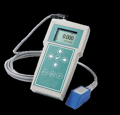
DFM 6.1
Dedicated instrument for liquids containing solids or air bubbles. Sensor mounted externally on steel, iron, PVC or ABS pipe.
PDFM 5.1
The ideal instrument for evaluating the performance of in-line flow meters. Fast installation, calibration and commissioning makes it ideal as a temporary in-line transmitter.
FEATURES
• Continuously frequency deviation measurement ensures precise fluid velocity data
• Can be installed without interrupting plant operation
• Intuitive programming menu
• Password protection for totalisation and calibration data
• Sensor unaffected by dirt or deposits
APPLICATIONS
• Wastewater
• Chemicals
• Sludge
• Viscous liquids
OPERATING PRINCIPLE
1. Sensor
2. Soundwave transmitted from sensor
3. Soundwave reflected back to sensor
4. Bubbles or solids reflect sound
88 FLOW METERS 1 4 3 2
6.1 PDFM 5.1
DFM
TECHNICAL SPECIFICATION - DFM 6.1
Liquid characteristics Required suspended solids or air bubbles with minimum cross section of 100microns, concentration 75ppm
Piping / DN and materials ½"...180" (12.7...4500 mm) Steel, stainless steel, cast iron, ductile iron, concrete-lined ductile iron, PVC, HDPE or any other sound-conducting pipe material, including pipe lined with a coating bonded to the pipe wall. Avoid pipes with deteriorated coatings that contain air
Velocity measurement range ±0.03 up to 12.2 m/sec
Accuracy ±2% of reading or 0.05 ft/sec (0.015 m/sec). Repeatability ±0.1%, Linearity ±0.5%
Display White, backlit - Display of instantaneous flow rate, totalisation, relay status
Programming 5-digit keypad
Analogue output 4...20mA opto-isolated (1000 ohm max.)
Control relay
Two SPDT, 5 A programmable for flow alarm and/or pulse output
Power supply 100...240VAC 50-60Hz (other on request), absorption 5 Watts max.
Enclosure Polyester IP66 NEMA4X. Clear polycarbonate front panel
Operating temperature -23...60°C (-10...140°F)
SENSOR SPECIFICATIONS
Model SE4-A
Assembly kit
Single-head ultrasonic with 7.6 m cable and SS mounting kit for pipes ½” (12.7mm) ID or larger. Certified for Class I Division 2, Groups A, B, C, D hazardous locations
Sensor mounting bracket for pipes with external diameter from 15 to 800 mm Gel of coupling (150g)
Operating temperature -40...150°C (-40...300°F)
TECHNICAL SPECIFICATION - PDFM 5.1
Flow rate range
± 0.46 up to 12.2 m/sec
Pipe size From ½“ up to 180” (12.7...4500 mm)
Display White, backlit matrix - displays flow rate, totaliser
Power input
Built-in NiMH battery for up to 18 hours continuous operation External charger with 100...240VAC 50/60Hz input
Outputs 4...20mA (500 ohm) when AC powered USB for Data log transfer by direct PC connection
Data logger
Programmable 300000 data point capacity, time and date stamped or formatted flow reports including total, average, minimum, maximum and times of occurrence
PC software For Windows 98 or higher. Retrieves, displays and saves data log files
Electronics operating temperature -23...60°C (-10...140°F)
Electronics enclosure
Carry case
Portable, ABS enclosure
Rated IP67 with protective molded foam insert
Accuracy ±2% of full scale, requires solids or bubbles minimum size of 100 microns, minimum concentration 75 ppm. Repeatability: ±0.25%, Linearity: ±0.5%
Calibration
Sensitivity
Built-in 5-key programming with user-friendly calibration menu. Password protected
Adjustable cut-off, damping: adjustable
SENSOR SPECIFICATIONS
Model PSE4
Sensor mounting kit
Clamp-on, single-head ultrasonic for pipes ID: ½”...180” (12.5 mm...4.5 m) with 3.4 m shielded dual-coaxial cable
SS pipe clamp and 5.3 oz. (150 g). Silicone coupling compound
Operating temperature -40...150°C (-40...300°F)
89 FLOW METERS
AVFM 6.1 & STINGRAY
"AREA VELOCITY" FLOW METER, FIXED OR PORTABLE

STINGRAY

AVFM 6.1
State-of-the-art instrument for the simultaneous measurement of fluid level and velocity for flow-rate calculation in open channels or pipes.
FEATURES
• Simple calibration
• Calibration parameters remain stored even in the absence of tension
STINGRAY
Portable instrument for the measurement of water level, velocity and temperature in open channels and partially-filled of pressurised pipes.
FEATURES
• Alkaline battery for extensive operating time
• Data stored to memory and presented as trend graphs and tables
• No calibration required
• Energy-saving display timeout
SUBMERGED SENSOR
• Measuring levels and velocity
90 FLOW METERS
AVFM 6.1
TECHNICAL SPECIFICATION - AVFM 6.1
Liquid characteristics Required suspended solids or air bubbles with minimum cross section of 100 microns, 75ppm concentration
Type of channels
Unfilled pipe, rectangular, trapezoidal, egg-shaped or custom channels
Accuracy Level: ±0.25% of measurement range. Velocity: ±2% of reading repeatability and linearity: ±0.1%.
Display White, backlit display - of instantaneous flow rate, totalisation, relay status
Programming 5-digit keypad
Data logger
Recording capacity of 26 million points. Includes USB output and Windows software
Analogue outputs Three 4...20mA opto-isolated (1000 ohms max.)
Control relays Two SPDT, 5 A programmable for flow alarm and/or pulse output
Power supply
100...240VAC 50-60Hz (other on request), absorption 5 Watts max
QZ02L SENSOR SPECIFICATION
Velocity measurement range 0.03...6.2 m/sec
Level measurement range
Operating temperature
Minimum head: 25.4 mm
Maximum head: 4.57 m
-15...80°C
Exposed materials SS316, epoxy resin, polyurethane
TECHNICAL SPECIFICATION - STINGRAY
Liquid characteristics Required suspended solids or air bubbles with minimum cross section of 100 microns, 75ppm concentration
Electronics enclosure Watertight, airtight, dust proof (IP67) polycarbonate
Accuracy Level: ±0.25% of range. Velocity: ±2% of reading
Display LCD displays: level, velocity, water temperature, battery and memory capacity
Operating temperature
-20...60°C (-4...140°F)
Instrument set-up Via software for Windows: logging time interval, site name
Data logger capacity
130,000 data points
Power 4 alkaline ‘D’ cell batteries
Software For Windows. Supports real-time monitoring, log file download and export, graph and data table presentation, level/velocity to flow conversion
Approx. shipping weight 4.5 kg
QZ02L SENSOR SPECIFICATION
Velocity measurement range 0.03...3.8 m/sec
Level measurement range
Minimum head: 25.4 mm
Maximum head: 4.5 m
Operating temperature -15...80°C (5 to 175°F)
Exposed materials SS316, polyurethane, epoxy
91 FLOW METERS
50 SERIES F/L
LEVEL METER WITH ULTRASONIC OR PIEZOMETRIC OP RADAR SENSOR


FEATURES
• Ultrasonic level measurement; single level, double level, differential level
• Automatic temperature compensation
• Pump operation: single, rotating or timed
• RS485 Modbus RTU serial output
• 2 x programmable analogue outputs
• 5 x relay outputs for intervention pump control thresholds
• 1 x relay output for instrument anomaly alarm, flow totalisation or level 2 alarm
APPLICATIONS
• Wastewater
• Industrial water
• Drinking water
• Cooling towers
TECHNICAL SPECIFICATION
Unit of measure
Level mt, cm, mm - temperature °C
Measurement fields Level 0...200 mt (in relation to the connected sensor)
Temperature -25°C...75°C
Precision ± 0.2% F.S.
Display Graphic TFT colour LCD resolution 480x272 visible area 95x93 backlit
Simultaneous display of: Level (absolute / differential & bar-graph for percentage of full scale), temperature, status of the digital outputs, alarm events Level 2, status of the analogue outputs
Controls 5 keys
Data logger
Serial output
Internal with 4 Mbit flash
One RS485 galvanically separated Modbus RTU
Analogue outputs Two galvanically programmable separated 1st output: level/temperature - 2nd output: level 2, differential, temperature
Relay outputs Five for thresholds - One for Alarm (max load 1A at 230Vac resistive)
Power supply
100...240Vac/dc 50-60Hz (Optional 24Vac/dc) - Isolation 4 kV
Average absorption <7W
Dimensions/weight (LxHxD) 144x144x122.5 mm - Weight: 1 kg
92 LEVELS
S425
ULTRASONIC LEVEL SENSOR
FEATURES
• Integrated sensor for temperature compensation
• PVDF body suitable for aggressive environments
• High-resolution 1mm measurement
• Double-threaded connection
• Immediate installation with removable IP67-rated connector
• Modbus RTU protocol
APPLICATIONS
• Drinking water
• Wastewater without persistent foam chemicals

TECHNICAL SPECIFICATIONS
Models
S425 C
S425 K
Measurement range 30...500 cm 50...1200 cm
Measurement method Ultrasonic with automatic temperature compensation
Emission angle 14° ±1° 10° ±1°
Accuracy ± 0.2% of measured distance (but not better than 2mm)
Resolution 1 mm
Operating temperature -10...75°C
Maximum operating pressure 0,5 bar...1,5 bar
Body materials PVDF – PCV
Thread
1” g.m./1.5” g.m 1” g.m./2” g.m
Degree of protection IP67 (IP68 optional)
93 LEVELS
METER
COMAPACT ULTRASONIC LEVEL TRANSMITTER

TECHNICAL SPECIFICATION
FEATURES
• Suitable for liquids and solids
• Range 0,25 ÷ 6 m/0,4 ÷ 10 m
• Power supply 24 Vdc; 12 Vdc
• Output 4 ÷ 20 mA (2 wire version); 4 ÷ 20 mA + 2 relays set (4 wire version); Modbus
• On request ATEX
• Remote control via smart phone (CHEMITEC APP)
Measuring range 0.25...6 m or 0.4...10 m (distances expressed are valid for measurements of perfectly reflective surfaces, otherwise the maximum measurable distance is reduced)
Temp. compensation Digital between -30...80°C
Accuracy ±0.2% (of the measured distance) but not less than ±3mm
Resolution 1 mm
Operating temperature -30...70°C; 80°C non-continuous
Operating pressure 0.5...1.5 bar (absolute)
Programming/display Removable module with 4 keys and dot matrix LCD (or via HART / Modbus RTU on request)
Housing material PC or Al/PP or PVDF (ATEX certified versions only of PVDF)
Mechanical installation 2”GAS M (PP flange DN80 optional)
Protection grade IP67
Power supply 24Vdc (20...30Vdc); 12Vdc (only 2 wires version)
Power consumption 2 wires version 0.6 W ; 4 wires version 1.5 W
Analogue output 4...20mA
Output relays Nr.2 - 3A 230Vac (n.a.) (only 4 wires version)
Digital communication 2 wires version (optional) HART; 4 wires version Modbus RTU
Ex-proof ATEX II 1/2G Ex ia/db IIC T4 Ga/Gb; II 1D Ex ta IIIC T135°C Da Tamb: -20...+60°C
94 LEVELS
RADAR LEVEL TRANSMITTER
FEATURES
• Suitable for level measurement in tanks with G1½” threaded connections
• Compact antenna allows mounting in pipes or small tanks
• Antenna extensions allow installation in the presence of insulation or other obstacles
• Continuous level measurement for liquids, pastes and sludges
• Measurement range: 10 m
• Maximum operating pressure: 3 bar
• 2/4 wire technology
• Radar pulses at 26 GHz (K band)
• ATEX certification II 1 G/D Ex ia IIC T6...3 Ga/ Ex ia IIIC T76°C...T146°C

TECHNICAL SPECIFICATION
Maximum measuring range 10 mt
Accuracy ± 10 mm
Resolution 1 mm
Frequency range K band (26GHz)
Housing / antenna material Aluminium; PVDF
Mechanical installation Threaded G1½”
Degree of protection IP67 / IP68 (sensor)
Electrical connection Pressure terminal blocks
Operating temperature PVDF antenna -40...130°C
Operating pressure -1...3 bar
Power supply 24Vdc; 230Vac
Certification ATEX
Analogue output 4...20mA
Digital communication HART/Modbus
Calibration 4 buttons or via HART / Modbus
Thermal stabilisation 5 minutes typical
Visualisation Extractable programming module VL602 (optional) with 4 keys and matrix LCD
95 LEVELS
RPL 55
RDR 81
RADAR LEVEL TRANSMITTERS

TECHNICAL SPECIFICATON
Housing / sensor material PP
FEATURES
• Non-contact continuous level measurement
• For liquids (max 20 m) and solids (max 10 m)
• 80GHz radar pulses
• Visualisation and configuration on removable display module
• Output: 4...20mA; 2 x configurable relays
• Remote control via smart phone (CHEMITEC APP)
• IP68 Version available
Mechanical installation 2" GAS M (DN80 PP flanges optional)
Degree of protection IP67 (IP68 optional)
Electrical connection Terminal blocks or waterproof connector IP68 (optional)
Operating temperature -20... +60°C
Maximum operating pressure 3bar
Power supply 24Vdc;12Vdc
Absorbed power 5W peak; 2.5W average
Analogue output 4...20 mA, max 750 ohm
Relay in output N° 2 3A 230 Vac (n.a.)
Digital communication Modbus RTU
Maximum measuring range 0.05...20 mt
Accuracy Measurement deviation ± 5 mm
Calibration
Visualisation
Vers. IP67 display opt. – 2 buttons – modbus – Bluetooth
Vers. IP68 display – modbus – Bluetooth
VL620/1 module (opt.) with 4 keys and LCD
96 LEVELS
RDR 75
RADAR LEVEL TRANSMITTERS
FEATURES
• Non-contact continuous level measurement
• For liquids (max 20 m) and solids (max 10 m)
• 80GHz radar pulses
• Visualisation and configuration on removable display module
• Output: 4...20mA; 2 x configurable relays
• Remote control via smart phone (CHEMITEC APP)

TECHNICAL SPECIFICATON
Housing / sensor material PC / PP wet part
Mechanical installation 2" GAS M (DN80 PP flanges optional)
Degree of protection IP67
Electrical connection Pressure terminal blocks
Operating temperature -20...+60°C
Maximum operating pressure 3 bar
Power supply 24Vdc
Absorbed power 5W peak; 2.5W average
Analogue output 4...20 mA, max 750 ohm
Relay in output N° 2 3A 230Vac (n.a.)
Digital communication Modbus RTU
Maximum measuring range 0.05...20mt max for liquids
Block distance 0.05 m
Accuracy Measurement deviation ± 5mm (If distance < 250 mm ± 10 mm)
Calibration 4 buttons or via Modbus RTU or Bluetooth via dedicated app
Visualisation
VL601 programming module (optional) with 4 keys and matrix LCD
97 LEVELS
ECHOSMART™
SLUDGE INTERFACE LEVEL METER

FEATURES
• Superior signal control and performance of control algorithms
• Flexible combinations between sensor, control unit and power supply unit
• Communication via RS-485 or Ethernet
• Large display with intuitive screens for quick parameter entry
• Soft-key operation
• Initialisation and automatic calibration for quick start-up with no process interruption
• Up to 16 EchoSmart™ sensors can be connected in a network with a single EchoSmart™ controller for optimised operation and significantly reduced costs
• Zigbee’s “self-healing” mesh technology eliminates unnecessary piping and wiring costs
APPLICATIONS
• Wastewater
• Miming industry
SUBMERGED SENSORS
• Network interconnection of up to 128 EchoSmart™ sensors
98 LEVELS
TECHNICAL SPECIFICATIONS
Components
Measuring range 0.305...10.0 m
Measuring principle Ultrasonic immersion
Measuring interval Adjustable –
Resolution 3.05 mm at 3 m
Accuracy 0.03 m at 3 m
Operating temperature 1...52°C
Calibration Factory calibrated; Adjustable speed of sound
Display
Monochrome graphic backlit 320x240 pixels; visual area 92x122 mm
Material ABS and epoxy 320x240 pixels ; visual area 92x122 mm
Self-cleaning wiper Silicone (optional) –
Environmental conditions – - 40...60°C
Power supply 15 VDC
Polycarbonate NEMA 4X with IP65 protection
Power 3W with wiper 6W 65 W (fuse)
Relay (optional)
Mounting Fixed or flexible
Dimensions
Standard 62x75 mm With wiper 146x75 mm
Weight Standard 1.02 kg With wiper 1.25 kg
Four 10A at 250 VAC; 10A at 30 VDC
Wall or pipe
235x229x115 mm
Approx. 1.36 kg
99 LEVELS
Sensor Control unit
–
–
–
–
–
–
–
–
HYDROSTATIC LEVEL TRANSMITTERS

FEATURES
• Superior technological performance in terms of overpressure, small temperature drifts, high stability and accuracy
• No separation liquid between the membrane and the pressure sensor APPLICATION
• Drinking water
• Industrial water
TECHNICAL SPECIFICATION
Measurement
Accuracy / stability
Operating temperature
Output signal
Power supply
Material
From 0.1 bar (1mH2O) to 20 bar (200mH2O)
±0.5 % f.s.
- 20...+70°C
4...20mA
10...36Vdc with two wires
Body and membrane AISI316L
Protection grade IP68
Dimensions
Sensor submerged Ø 27 mm; Ø 16 mm on request
100 LEVELS
KPL
HYDROSTATIC HEAD LEVEL TRANSMITTER
FEATURES
• Designed specifically for wastewater
• Accuracy: ± 0.5%
• Range: 1...200 mH2O
• Immersed sensor protection (wet part): IP68
• Power supply: 12...30Vdc (2-wire)
APPLICATION
• Wastewater
• Chemical industry

TECHNICAL SPECIFICATION
Measurement range
From 0...0.4 mH2O to 0...200 mH2O
Operating temperature -10...+50°C
Accuracy ±0.5 % f.s
Sensor material Immersed PVC (ø 46 mm)
Capacitive sensor Golden ceramic membrane
Shielded cable material
Analogue output
PU Ø 7.5 mm
4...20 mA
Power supply 10...36 Vdc (2 wires)
101 LEVELS
KWL
PIEZORESISTIVE PRESSURE TRANSMITTER

CPT
COMPACT PRESSURE TRANSMITTER

FEATURES
• Suitable for continuous level measurement of liquids, gases and vapours
• Small pressure transducer offers maximum reliability and safety
• Accuracy: ±0.25%
• Cost-effective solution
• Threaded, sanitary and vacuum connections
FEATURES
• Suitable for aqueduct and water-treatment applications
• Accuracy: ±0.2%
• Cost-effective solution
• Threaded process connections
• Capacitive sensor with ceramic membrane
• High mechanical resistance to over-pressure
102 PRESSURE
KPT
SPT
PIEZORESISTIVE PRESSURE TRANSMITTERS
FEATURES
• Designed for use in industrial processes
• High rangeability and multiple connection options
• Innovative technology delivers precise measurement and stability over time
• Internal temperature sensor corrects measurement deviations caused by thermal variations
• Accuracy: 0.075%
• Relative and absolute measurement
• Process connection: threaded, male or female and by vacuum
• HART communication
• Parameter setting via display
• Self-diagnosis and fast response time
SDT

DIFFERENTIAL PRESSURE TRANSMITTER
FEATURES
• Especially suited to installations in processes demanding high accuracy and stability
• Capable of measuring very low differential pressures from 1 mbar (10 mm H2O)
• IP67 rated for protection against dust and water jets
• Fully programmable via backlit matrix display and two external watertight buttons
• Accuracy: 0.075%
• Range: 1 mbar – 20 bar
• HART communication
• Parameter setting via display
• Self-diagnosis and fast response time
• ATEX compliant

103 PRESSURE
ACCESSORIES

IMMERSION SENSOR HOLDER 106
S315 Range
Jointed support and installation
INSERTION SENSOR HOLDER 108
S305 INS • S305/M
BYPASS SENSOR HOLDER 109
PSS8
INSERTION SENSOR HOLDER 110
PSS3 • SPP • SPPFIL
PRE-ASSEMBLED PANELS 111
Paneltec Series
With many years of experience, Chemitec has developed a wide range of accessories for the installation of sensors and controllers, which make it easy to install and maintain the measuring system.
105 ACCESSORIES 1 Protection canopy 2 Measuring device 3 Floor slab with pole h = 600 mm Floor slab with pole h = 1700 mm 4 Wall bracket 5 L = 700 mm extension 6 D42 sensor holder 7 Support for D42 sensor holder 8 Measuring Sensor 6 8 1 2 3 4 5 7
DIAGRAM OF ACCESSORIES
INSTALLATION BRACKETS
S315
IMMERSION SENSOR HOLDERS

TECHNICAL SPECIFICATION
Model Material Operating
S315 Polypropylene (PP) body
Nylon fixing screw NBR O-Rings
S325/T Plexiglass tube
Polypropylene (PP) protection and cap
Nylon fixing screw NBR O-Rings
max 80°C
max 80°C
Immersion sensor holder
S315 for single D42 electrode
S315/2 for two D63 electrodes
S315/3 for three D63 electrodes
S315/T with KCI tank
S315/T/2 for two D12 electrodes with KCI tank

TECHNICAL SPECIFICATION
Model Material Operating
S315/F Polypropylene (PP) tube and cap Nylon fixing screw NBR O-Rings
max 80°C
Immersion sensor holder
For turbidity/suspended solids sensors

TECHNICAL SPECIFICATION
Model Material
S315/O Polypropylene (PP) tube and cap
Nylon fixing screw
PVC 45° fitting NBR O-Rings
Operating Temperature
max 80°C
Immersion sensor holder
For S423-C-OPT oxygen sensor and S401/6 DF/DG pH and redox digital/differential electrodes
106 ACCESSORIES
temperature
Temperature
SENSOR HOLDER SUPPORT
JOINTED & FIXED VERSION

BRACKET FOR SENSOR HOLDERS & ULTRASOUND SENSORS
• SS316 material
• Available with fixed or swivelling arm
• 800, 1400 mm or telescopic length 700...1200 mm arm
• U or L bracket for sensor holders/ ultrasound sensors
JOINTED SUPPORT
• Black PVC articulated parts and sensor holder support
• SS316 plates and fixings
• SS316 fixing screws
• Suitable for supporting Chemitec Ø 42mm sensor holders, the articulated support rotates and tilts for multiple configurations

STANDING POLE SUPPORT
• Standing pole for floor mounting or poolside installation
• Designed for use with Ø 42 or 63mm immersion sensor holder
• Allows for secure, strong mounting

107 ACCESSORIES
S305 INS
BRACKET FOR INSERTION SENSOR FOR TURBIDITY/SS

S305/M
BYPASS SENSOR HOLDER
FEATURES
• Used for turbidity / suspended solids sensors
• Mounted onto pipes
TECHNICAL
SPECIFICATION
Body material SS316
Ball valve DN 40 for extraction of the sensor without interruption of the process
Connection Welded for mounting on pipe
Complete with Safety sensor fixing brackets
FEATURES
• Modularity allows alternative sensors holders to be mounted
• No moving mechanical parts
• Easy emptying and cleaning
TECHNICAL
SPECIFICATION
Materials
Black PVC and plexiglass body, aluminium plate, NBR seals
Operating Temperature 0...50°C
Maximum operating pressure 6 bar
Flow rate min 60l/h - max 100l/h
108 ACCESSORIES
BYPASS SENSOR HOLDER
PSS8-A
Bypass sensor holder for three sensors Ø 12mm
Pressure: up to 2 bar
Temperature: up to 50°C
Transparent vessel pH range: 4,0...10 pH
Sensor types
pH and ORP (redox) 12 mm
pH and ORP (redox) 13.5 mm
Temperature: 12 or 13,5 mm
Conductivity: 12 or 13.5 mm
Oxygen: 13,5 mm
PSS8-A1
Bypass sensor holder for three sensors Ø 12mm
Pressure: up to 2 bar
Temperature: up to 50°C
Black vessel
pH range: 2,7...12 pH
Sensor types
pH and ORP (redox) 12 mm
pH and ORP (redox) 13.5 mm
Temperature: 12 or 13,5 mm
Conductivity :12 or 13.5 mm
Oxygen: 13,5 mm
PSS8-B1
Bypass sensor holder for one sensor Ø 35 or 42mm
Pressure: up to 2 bar
Temperature: up to 50°C
Black vessel
pH range: 2,7...12 pH
Sensor types
Turbidity 42 mm
Oxygen 35 mm


109 ACCESSORIES
PSS8
PSS3 • SPP • SPPFIL
PROBE HOLDER FOR DIRECT INSERTION INTO PIPE


TECHNICAL SPECIFICATION
FEATURES
Insertion in-line probe holder with different materials and mechanical arrangements for a wide range of plant applications
110 ACCESSORIES
Model Connection Sensor connection Maximum temperature Maximum pressure Materials PSS 3 ½” G.M PG 13.5 or Ø 12 mm 60°C 6 bar PVC SPP 1”G.F PG 13.5 60°C 16 bar PP and PVC SPPFIL ¾” or 1”1/4 G.M PG 13.5 80°C 16 bar PP PSS3 SPP SPPFIL
PANELTEC SERIES
PRE-ASSEMBLED PANELS
FEATURES
The wide range of Chemitec products is enriched with new integrated systems for ease of use and operation.
Controllers, sensors and measuring cells are pre-assembled on polypropylene panels. The only required operations are the links to the electric and hydraulic networks.
Paneltec is a modular system that can be expanded to measure up to four parameters with a relevant controller.
The standardised solutions of the Paneltec series meet the needs of the most advanced operators and can be integrated with additional modules for the dosing or analysis of specific parameters, configuring the system according to customer requirements.

111 ACCESSORIES
WORLDWIDE DISTRIBUTOR NETWORK
Thanks to flexible and reliable instruments, user-friendly solutions, outstanding technical skills and continuous improvement, we are selected as an ideal partner and continue to increase our international presence.
CHEMITEC SRL
Via Isaac Newton, 28 50018 Scandicci (FI) Italy
Phone +39 055 7576801
Fax +39 055 756697
sales@chemitec.it • www.chemitec.it
CHEMITEC LTD SALES SUBSIDIARY Room 901, Floor 9 108, Yuyuan Road Shanghai (PRC) Phone +86 021 3331 1193
Fax +86 021 3331 1193-808 info@chemitec.asia • www.chemitec.asia
Chemitec reserves the right to amend and change speci fi cations without prior notice. All pictures shown are for illustration purpose only. Actual product may vary due to product enhancement. Published data may be subject to change.
© 2024 Chemitec
