Kriti Chaudhry
http://issuu.com/kritichaudhry
kritichaudhry5@gmail.com
kritic2@illinois.edu
5616 Pershing Ave
Saint Louis, MO 63112
Skills
cOre skills
Space Planning
Design Development
Construction Documentation
Construction Administration
technical
Revit, BIM360, AutoCAD, Navisworks
Bluebeam and Newforma
Adobe Photoshop, InDesign, and Illustrator
SketchUp, Rhinoceros, Enscape
Microsoft Office, OneNote
Activities & Interests
cOmmUnity engagement
Project Pipeline - NOMA Saint Louis
Design Lab - AIA Cincinnati
Rebuilding Together
Keep Cincinnati Beautiful
Clean Up Cincy
Cincinnati Cultural Arts Center
extra-cUrricUlar
Gargoyle Honors Society Public Relations
Ricker Report Editor
Solar Decathlon Design Team Member
Zindaa UIUC Dance Team Member
Alpha Rho Chi Professional Fraternity Member
UC Dhadak International Dance Team Member
interests
Dance, Music, Art, and Travel
Work
christner architects
Architectural Associate
Saint Louis Symphony Orchestra, SSM Wentzville, SLCC Wildwood, and SIUE Health Sciences Building
DEI Committee and Social Committee Member
tra design
Designer and Project Coordinator
Residential, Workplace, and Educational
glick-bOehm & assOciates
Intern Architect
Public Works and Workplace
architectUre inc.
Intern Architect
Corporate Workplace
fOrrest perkins
Intern Architect
Active Adult Housing
Education
University Of illinOis at Urbana-champaign
July 2021- Present
Saint Louis, MO
June 2018- June 2019
Cincinnati, OH
May 2017- July 2017
Charleston, SC
Aug. 2016- Dec. 2016
Reston, VA
Jan 2016- April 2016
Washington, D.C.
2019-2021 Illinois School of Architecture
Master’s of Architecture
Urbana-Champaign, IL
vii internatiOnal WOrkshOp- la salUt stream Spring 2021
Two week workshop analyzing and redifining the relationship between the Collserola nature park and Llobregat river in Spain
University Of cincinnati
College of Design, Archtecture, Art and Planning
B.S. Architecture
said travel stUdiO
Two month travel studio through South-East Europe concentrating on wood and stone architectural designs and construction techniques
Darmstadt Fellowship 2020
Graduate Studio Excellence Awards- Honorable Mention
Goetsch Fellowship
Winner - Future of Work Competition
Dean’s List
International Outreach Scholar
Achievements Exhibitions
Earl Prize Nominee Exhibition
DAAP Works
Holz und Stein

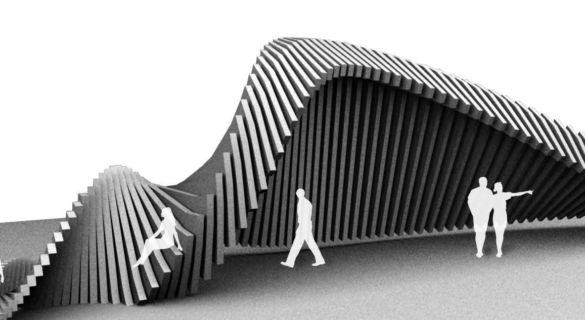
Contents 01 02 03 04 05 06 07 08 PROFESSIONAL EDUCATIONAL PERSONAL SAINT LOUIS SYMPHONY ORCHESTRA cultural TECHNICAL DRAWINGS professional work THE MEETING PLACE healing outpost IN SITU HOME residential TRANSPOSE competition - future of work HOLZ UND STEIN framework SKETCHES HEALTH SCIENCES BUILDING higher education
01 Health Sciences Building
Southern Illinois University Edwardsville
Size: 176,000 SF
Status: Est. Completion Summer 2025
Phases: Design Development and Construction Documentation
Design Architect: Christner Architects
Architect of Record: Lamar Johnson Collaborative
This is a new facility on the SIUE campus to consolidate the Nursing, Pharmacy, Public Health, and Occupational Therapy. The program includes office, research, classroom, and simulation spaces, with an important goal of acting as a new campus gateway.
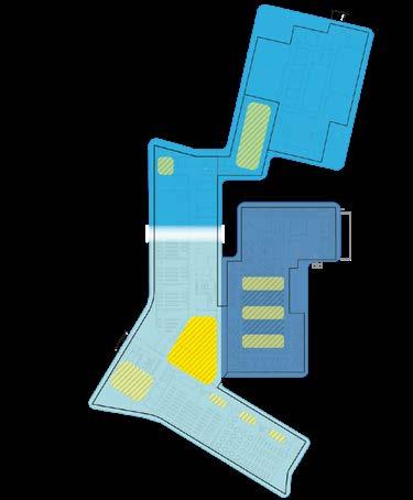
The design creates a strong sense of connectivity for the Health Science community at SIUE. This connectivity is facilitated through the project’s site response, contextual response, planning organization and its interior and spatial design. The myriad of connections generated by this design will improve the quality of healthscience research and instruction, will encourage more collaboration and innovation and will support a vibrant sense of community and belonging.
contributions: massing, exterior envelope design, wall sections, and exterior details


Design Concept
The design creates a strong sense of connectivity for the Health Sciences community at SIUE.
Main Campus: Horizontal grain punctuated with vertical towers.
The varied levels of connection:
- connection with the main campus through its architectural character
- research space connects with instructional space through proximities
- the School of Nursing and School of Pharmacy connect through shared instructional space, faculty and administrative adjacencies
- collaborative spaces for the all members
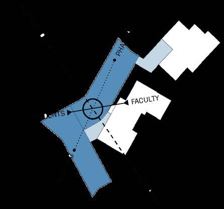
The building features a main central commons that celebrates and symbolizes inter-professional teaching and research. This serves as the connection between students and faculty while also creating a welcoming entrance to the faculty suites.
New Health Sciences: Horizontal grain punctuated with vertical stair tower at entry.
concealed and partially absorbed
SIUE HEALTH SCIENCES BUILDING | OCTOBER 20, 2022
This element also gives landmark presence to the building and alludes to the prominent towers on the Main visual analysis below).
Contextual Response
Main Camous: Horizontal grain punctuated with vertical towers
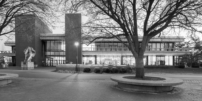
Campus: Horizontal grain punctuated vertical towers. CONTEXTUAL RESPONSE design of our building is rooted in a contextual response to the architecture of the Main Campus, it has its own aesthetic identity that responds to its specific program and site conditions. Like the Main Campus, our design has horizontal volumetric composition. This horizontality occurs through the placement and rhythm of windows, organization of façade materials. A vertical stair tower juxtaposes our building’s horizontal massing and announces
220 220 200 1 STORY ALIGNMENT WITH 220 2 STORY ALIGNMENT WITH 200 3 STORY BAR FACING UNIV. DRIVE
CONTEXTUAL ANALYSIS
VERTICAL EXPRESSION
MASSING DIAGRAM
HORIZONTAL EMPHASIS VERTICAL EXPRESSION
Site Response
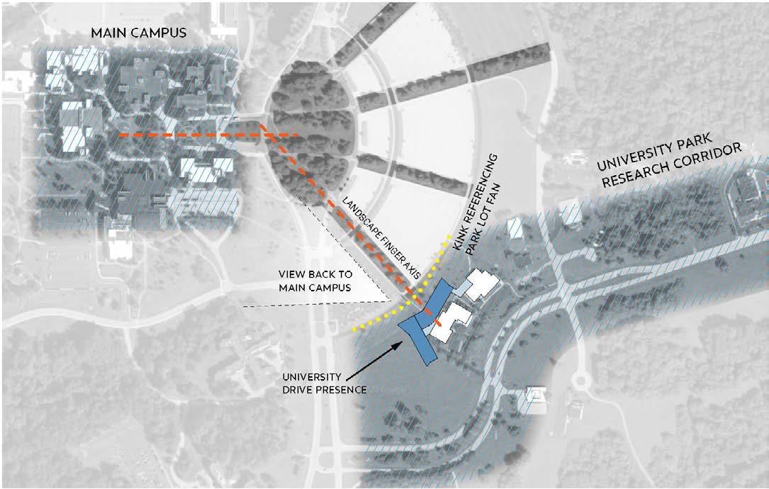
The strategy was to reduce costs and provide the maximum amount of program spaces, the design repurposes two existing buildings. The new ‘L’ shaped construction connects to one building and bends alond the curved road to connect to the southern side of the second building. The connection is made with a two story wing, which conceals the dated western facade of the existing building. This in turn gives the building a dynamic and inviting character. The new building transitions to a more prominent three story mass at the southern edge of the site. The volume, coupled with a vertical stair tower, emphasizes the Health Sciences and creates a strong presence at the campus entry.
The building entry is aligned with the existing landscape finger to ensure a natureal, shaded pedestrian way links the new building back to capus. The long bent facade faces northwest ensuring excellent daylighting and reduced energy demand.
 New Health Sciences: Horizontal grain punctuated with vertical towers
Elevation Design Development
Schematic Design
Original
5. Final modification of brick organization to make facade more engaging
1. Revision to stair tower 2. Modifications to brick organization 3. Match window rhythm across levels
4. Strategic introduction “limestone” colored zones to connect to main campus
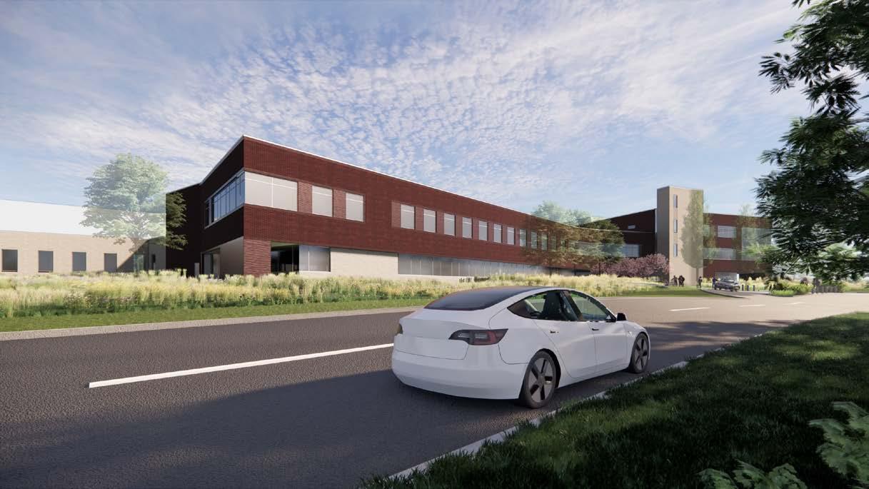
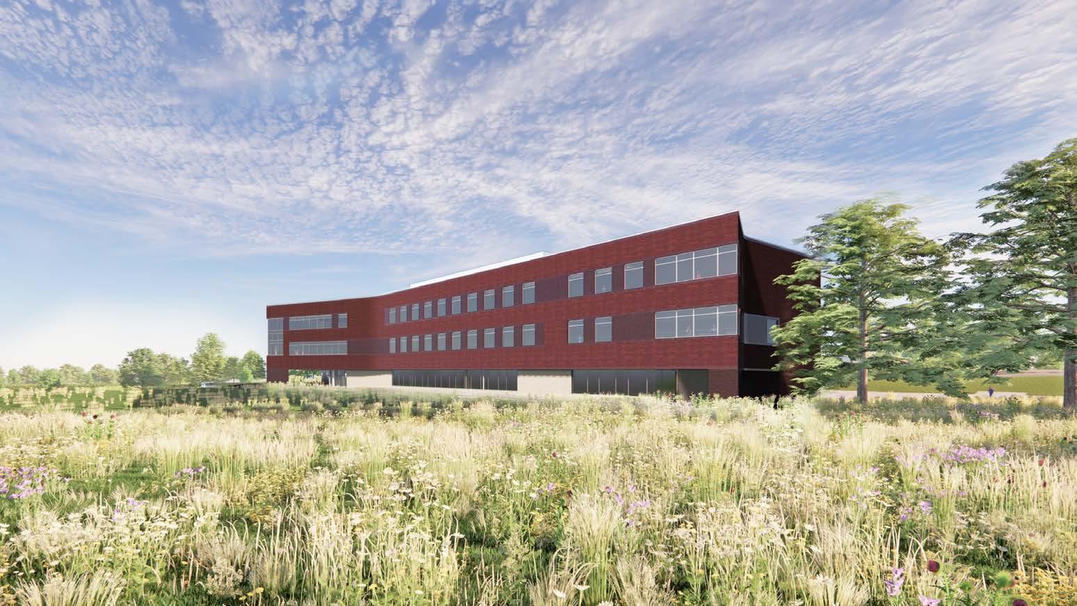
Rendered Views View from NW
from South
View
Saint Louis Symphony Orchestra
Saint Louis, Missouri
Size: Renovation and 65,000 SF expansion
Status: Est. Completion 2025
Phases: Design Development, Construction Documentation, Construction Administration
Design Architect: Snohetta
Architect of Record: Christner Architects
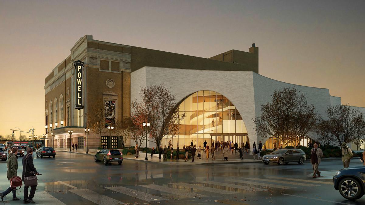
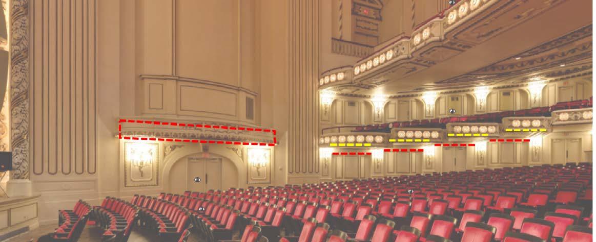
Powell Hall is one of America’s most acoustically renowned and visually stunning concert halls and home to the St. Louis Symphony Orchectra. The objective of this project was to renovate and expand the 98-yearold building to preserve and enhance this civic treasure. The redesign and addition maintains the historic integrity and character of the building.
Project Strategies included elevating the visitor and user experience by improving the accessibility, comfort and amenities, creating functional spaces that support the back of house activities, an introduction to versatile spaces for gathering and performance.
Focusing on the renovation of Powell Hall, many of the existing spaces were reworked to fit new programs. The structure and low head heights added additional levels of complexity when improving the accesibility. We had to work in unison with our acoustic and theater consulatants especially to create a version that compliments the historical architecture but improves the user experience and does not compromise the acoustics.
contributions: Powell Hall Renovation - auditorium and lobby space

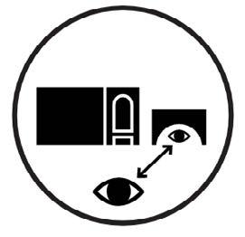
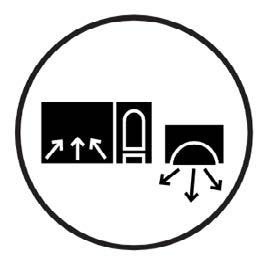
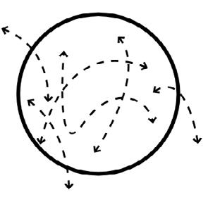





Design Concept
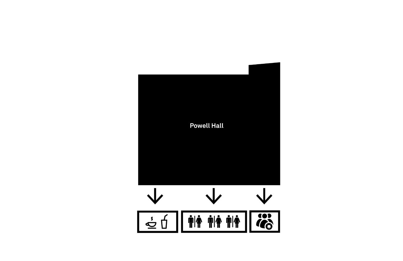
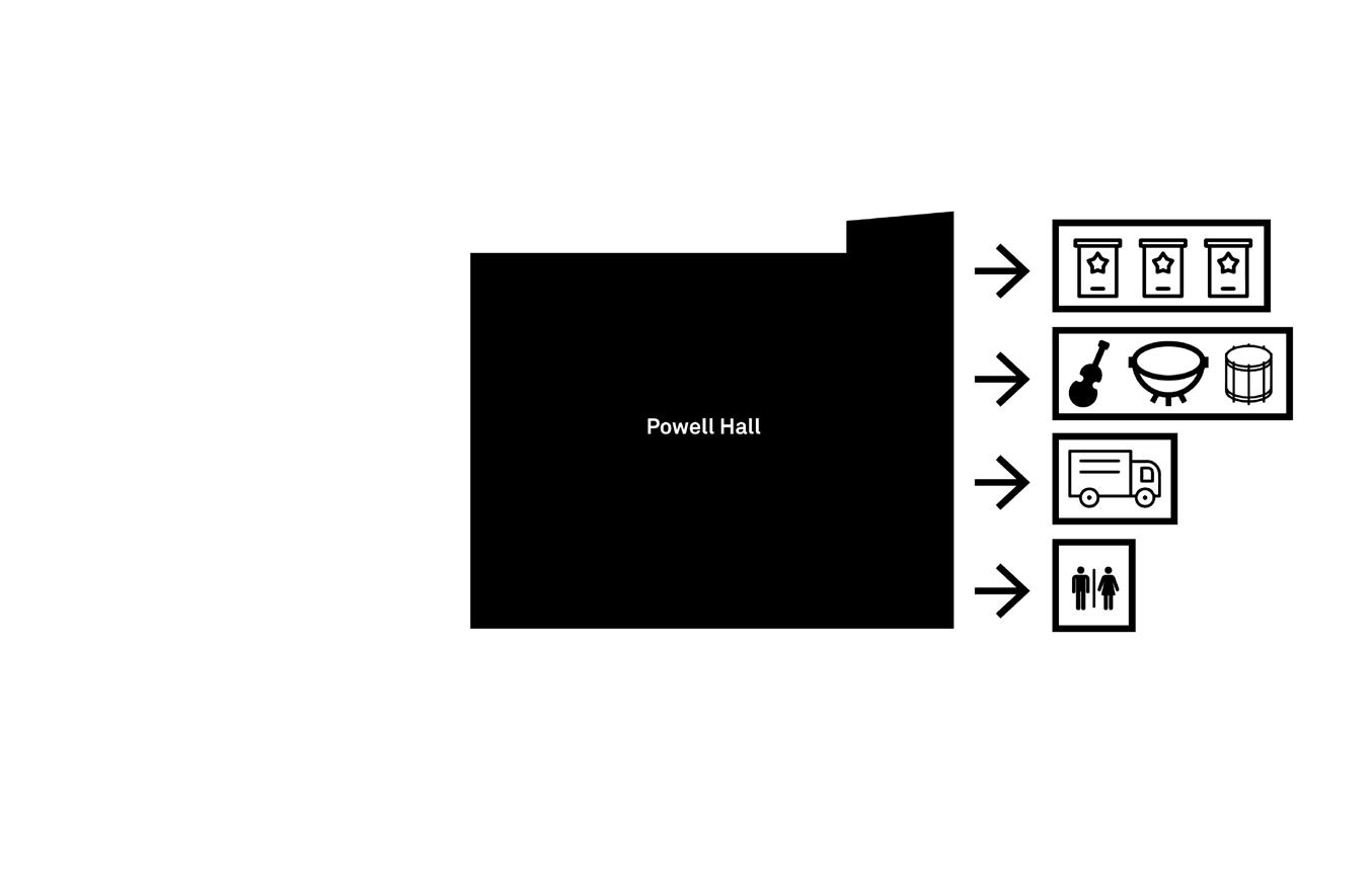
Key Powel Hall Elements
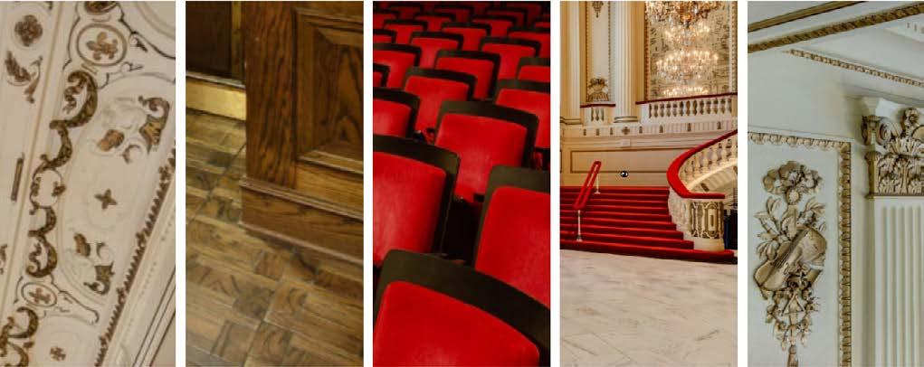
preserving history
New Back of House
New Visitor Services
Delmar Blvd.
Education & Learning Center

Planning:
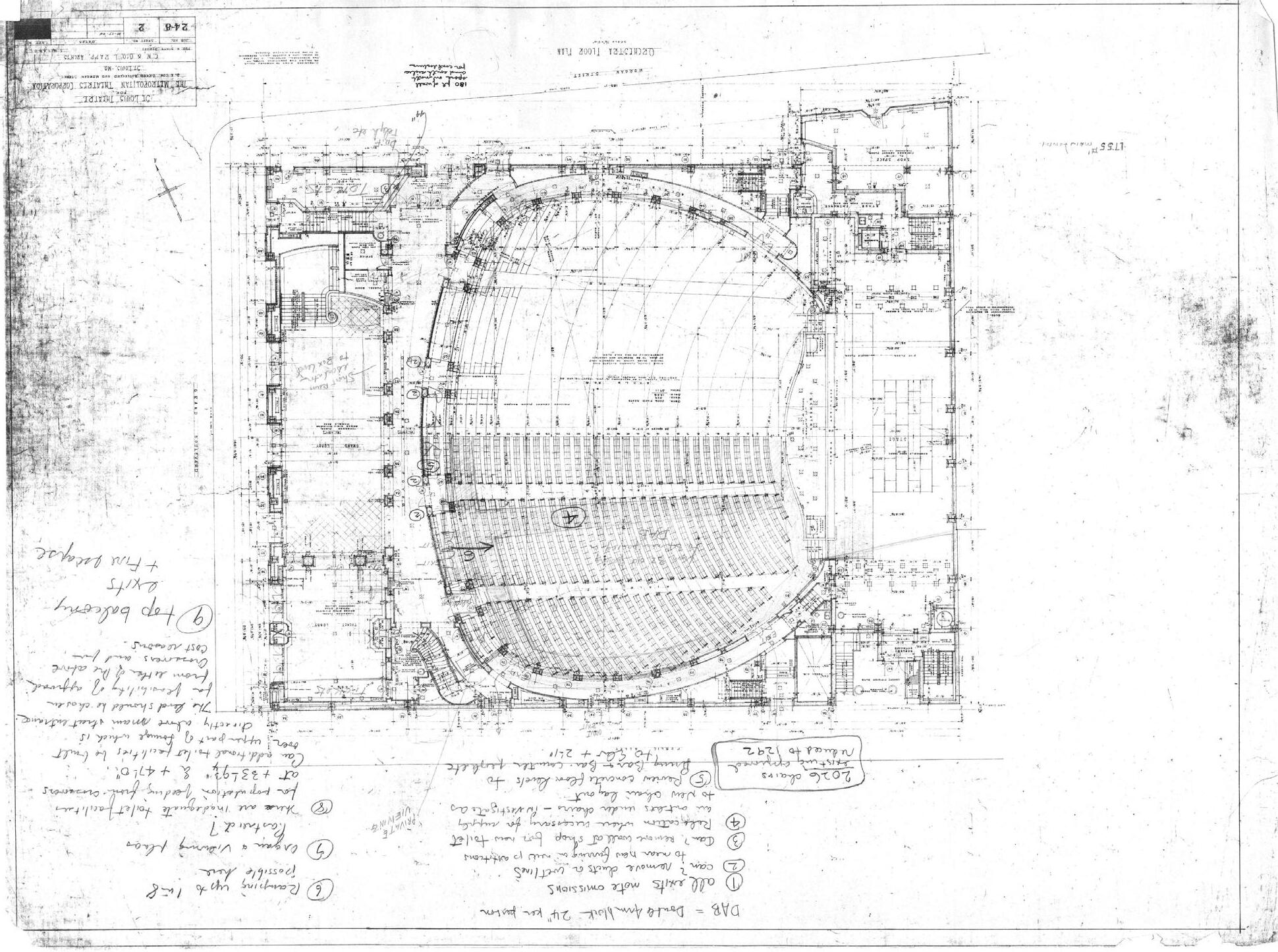
• relayout of auditorium seating
• more accessible seating across Powel Hall
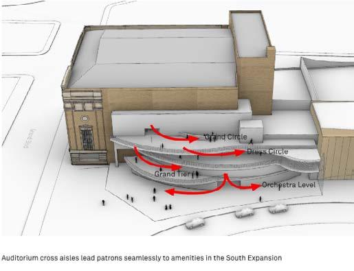
• connection to front of house addition - key for accessibilty
• include visitor services and concessions
• revitalize existing entry on Delmar Blvd

Renovation Scope
vvvv
strategic interventions
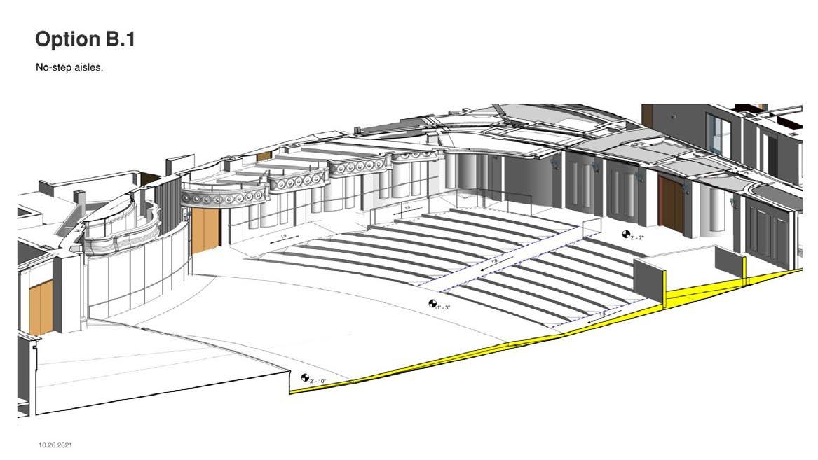
Option 1
• No-step aisle
• Tiered seating aisles
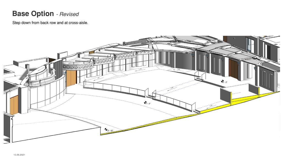
Option 2
• Step down from back row and cross-aisle
• no step route at perimeters
Orchestra Level Modifications Theater constraints concrete beam b.o. slab b.o. beam
A ramp is developed at the perimeter to provide no-step access to the NW and SW seating
West exit provides wheelchair accessible route to the rear seating area
South exit provides a wheelchair accessible rout to the cross-aisle and lower seating area
Over-pour strategy avoids impact to impact to existing floor slab

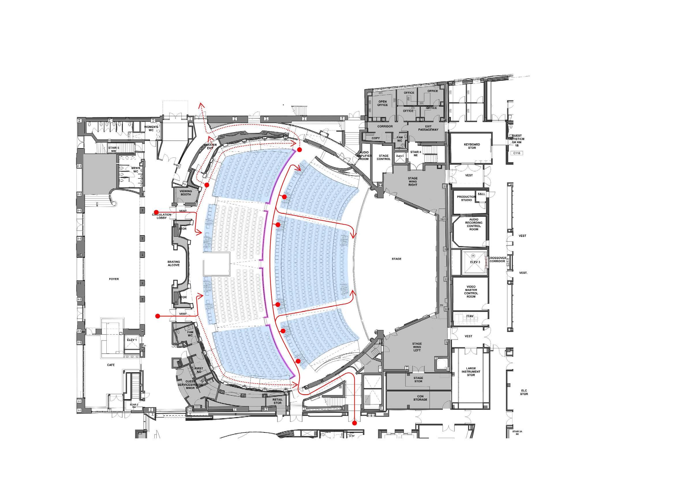
Final Layout

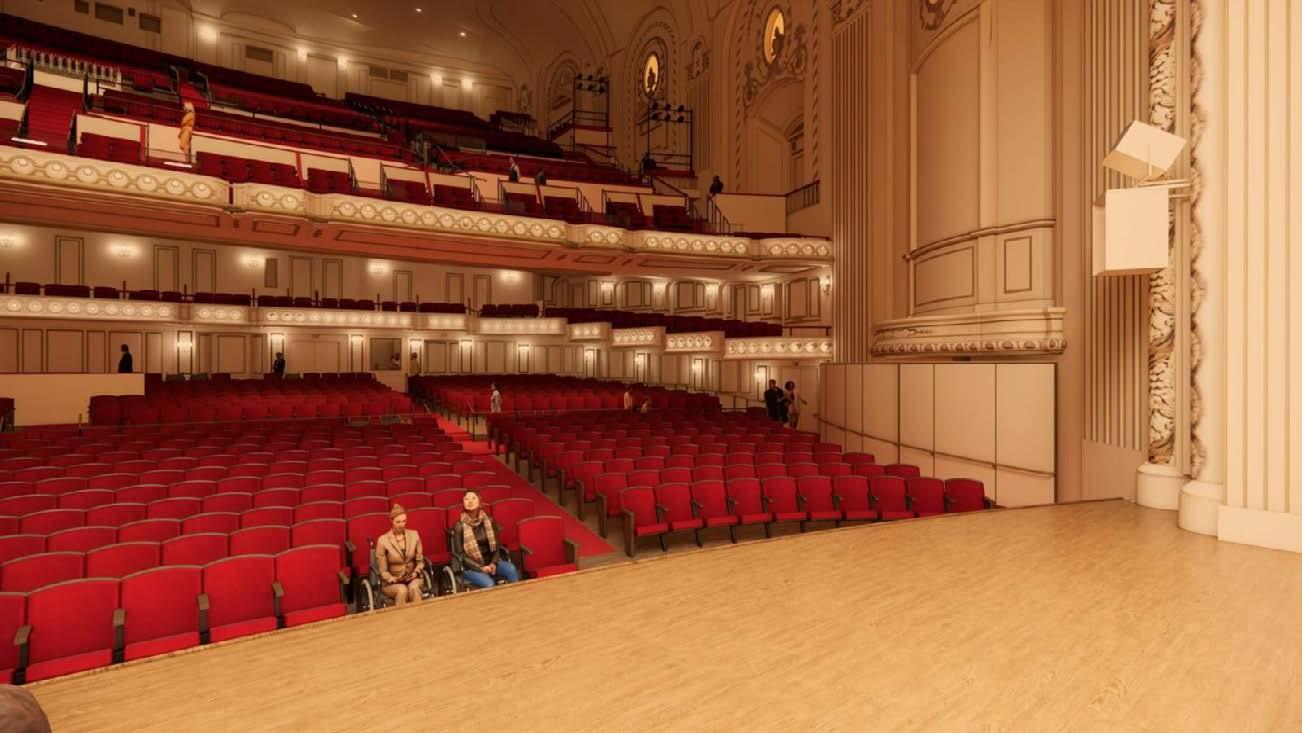
Orchestra Renderings
096519 - ACOUSTIC RUBBER UNDERLAYMENT
BARRIER
8" DIFFUSER
3" CONCRETE TOPPING SLAB GEO FOAM 5/8" WOOD FLOOR
10" CORE
B4 A5.21A.2 B1a A5.21A.2 C5 A1.02 C3 A1.02 2' - 9"2' - 2 1/2" 10' - 5" 3' - 11 1/2" 16' - 0 3/4" 2 - 5 3/4" 1" R 8811 3' - 5 1/2"4' - 4 3/4" 12' - 0 3/4" 4' - 3" 20' - 0 1/2" 9 3/4"1 1/4"9 1/2" 22' - 8" 11"11 3/4"10 1/2"8' - 9 3/4" 2'1 1/4"3'5" 23'8 1/2" 1"4' 0 1/4"1 1/2"7'11 1/4" 2'7 1/4"5'3 1/ 2"2' 3"1'6 1/2"2' 6 3/4"3'4 1/4"3'0 1/ 2" -9 1/2" -8 1/4" -1' - 2" 2' - 2" -1' - 2" 6" -8 1/4" -9 1/2" -1' - 2" -10" 1' - 6" 1' - 6" 1:15 1:20 1:20 1:18 1 8 1:9 -1' 1' - 0 1/2" 1' - 0 1/2" 1' - 9" 1' - 9" 2' - 2" 6" 2' - 2" 1' - 3" 1' - 3" 2' - 2" 1:12 D4 A1.02 -1' - 2" C3 A1.02 -10" -10" D4 A1.02 2' - 2" 1' - 6" 1' - 3" 2' - 2" 1' - 10" 11" 11" 11" -1' - 5 1/4" -1' - 2" 1' - 4 1/2" D8 A7.02 -7 1/2" -9 1/2" -1' 8' - 11 1/4" 14' - 7 3/4" 1' - 10" 9' - 1 3/4" D8 A7.02 D4 A4.23.00 0" 0" 0" 0" B C D E 1 2 3 1/32" = 1' -0" 16'32' 64' 8' 1/16" = 1' -0" 8'16' 32' 4' 1/8" = 1' -0" 4'8' 16' 2' 1/4" = 1' -0" 2'4' 1' V1 Autodesk Docs://SLSO/SLSO-ARCH-EXP-2022.rvt 12/5/2022 1:26:36 PM 1/4" = 1'-0" E1 OVERALL PLAN -LEVEL 01 -ORCHESTRA LEVEL LOBBY B3 SLUMB CONDITION -SLAB EDGE 3D EXISTING PLYWOOD; PAINT 3/4" 1 1/2" ALIGN TOP OF TRIM TO TOP OF LOUVER TOP PROFILE OF BASE ASSEMBLY TO RETURN TO BUILT OUT BASE SHOE LOUVER CUSTOM FLOORING TRANSITION. SEE 2X3 FRT WD SLEEPER @ 19" OC TWO LAYERS OF 1/2" (NOMINAL) PLYWOOD STAGGERED JOINTS CONCRETE TOPPING SLAB; THICKNESS VARIES. COORD WITH STRUCTURAL AND EXISTING CONDITIONS EXISTING CONCRETE SLAB VAPOR RETARDER WDF-2 8" DIFFUSER 5/8" WOOD FLOOR 2X3 FRT WD SLEEPER @ 19" OC TWO LAYERS OF 1/2" (NOMINAL) PLYWOOD STAGGERED JOINTS 12" (NOMINAL) SLEEVE EXISTING CONCRETE SLAB VAPOR RETARDER WDF-2 8" DIFFUSER 3" CONCRETE TOPPING SLAB GEO FOAM 5/8" WOOD FLOOR 10" CORE SLAB FINISH BARRIER ACOUSTIC RUBBER UNDERLAYMENT 2X3 FRT WD SLEEPER @ 19" OC TWO LAYERS OF 1/2" (NOMINAL) PLYWOOD STAGGERED JOINTS CONCRETE TOPPING SLAB; THICKNESS VARIES. COORD WITH STRUCTURAL AND EXISTING CONDITIONS EXISTING CONCRETE SLAB VAPOR RETARDER CPB-1 WDF-2 6" X 1/2" WOOD BASE. FINISH TO MATCH SCHEDULED FLOORING. KERF BACK AS REQUIRED TO CONFORM TO RADIUS SCHEDULED THEATER RAILING GEOFOAM -10 1/8" DIMENSION LOCATION EDGE OF SLAB PLANS 1/2" WOOD BLOCKING CUSTOM NOSING WITH EASED EDGE TOP AND BOTTOM. FINISH TO MATCH SCHEDULED FLOORING 1/2" DIMENSION AT POST. OVERHANG WILL BE GREATER AT MIDPOINT OF SEGMENTED CUSTOM NOSING. NOT TO EXCEED 1 1/4" C7 A1.02 2X3 FRT WD SLEEPER @ 19" OC TWO LAYERS OF 1/2" (NOMINAL) PLYWOOD STAGGERED JOINTS CONCRETE TOPPING SLAB; THICKNESS VARIES. COORD WITH STRUCTURAL AND EXISTING CONDITIONS EXISTING CONCRETE SLAB VAPOR RETARDER WDF-2 GEOFOAM CPB-1 SCREW FASTEN THROUGH EXPANSION GAP TO 1" X (AS REQUIRED) WOOD BLOCKING CUSTOM FLOORING TRANSITION. SEE TYP CUSTOM FLOORING TRANSITION DETAIL FOR MORE INFORMATION WOOD BLOCKING MOVEMENT GAP 1" FLOORING 1/2" TYP 1/4" TYP 1/2" TYP CUSTOM FLOORING TRANSITION. FINISH TO MATCH SCHEDULED FLOORING. ANCHOR TO SUBSTRATE AT 12" ON CENTER WITH A BLACK HEADED SCREWED FASTENER. PRE-DRILL AND SET FASTENER FLUSH WITH TOP OF WOOD 3" C5 A1.02 1/2" 1" 2 1/4" 3 3/4" CURVED FACE OF WOOD TRIM BELOW CURVED FACE OF CONCRETE BELOW WOOD NOSING. SEGMENT WOOD NOSING WITH MITER CUTS AT EACH THEATER RAIL POST. THEATER RAIL POST. WRAP PERIMETER OF THEATER RAIL POST WITH 1/4" THICK CORK FOR FULL DEPTH OF THE SCHEDULED WOOD FLOORING ASSEMBLY. TRIM CORK FLUSH WITH TOP OF FINISH FLOOR. SCHEDULED WOOD FLOORING ASSEMBLY; NOTCH AND SCRIBE AS REQUIRED AT THEATER RAIL POSTS. SCHEDULED WOOD FLOORING ASSEMBLY; SCRIBED TO SEGMENTED WOOD NOSING NOT TO EXCEED 1 1/4" 2X3 FRT WD SLEEPER @ 19" OC TWO LAYERS OF 1/2" (NOMINAL) PLYWOOD. STAGGERED JOINTS CONCRETE TOPPING SLAB; THICKNESS VARIES. COORD WITH STRUCTURAL AND EXISTING CONDITIONS EXISTING CONCRETE SLAB VAPOR RETARDER WDF-2 CPB-1 AT CARPETED AREAS OMIT FINISHED WOOD FLOORING AND SUBSTITUTE 3/8" PLYWOOD UNDERLAYMENT BENEATH CARPET CUSTOM CARPET TRANSITION. SEE TYPICAL CUSTOM CARPET TRANSITION DETAIL FOR MORE INFORMATION CUSTOM CARPET TRANSITION. FINISH TO MATCH SCHEDULED FLOORING 1" 3/8" MATCH SCHEDULED FLOORING 0" 0" 0" 0" 3 4 5 6 7 A B C 1" = 100' -0" 50' 100' 200' 25' 1" = 60' -0" 60' 120' 240' 1" = 40' -0" 20'40' 80' 10' 1" = 50' -0" 25'50' 100' 1 1/2" = 1'-0" B5 ORCHESTRA WOOD FLOOR ASSEMBLY -3" -8" CONCRETE SLAB 1 1/2" = 1'-0" B4 ORCHESTRA WOOD FLOOR ASSEMBLY 3" CONCRETE SLAB 1 1/2" = 1'-0" C5 SECTION -ORCHESTRA FLOOR CROSS AISLE STEP 1 1/2" = 1'-0" C3 SECTION -ORCHESTRA FLOOR REAR STEP 3" = 1'-0" B7a TYPICAL CUSTOM FLOOR TRANSITION 1 1/2" = 1'-0" C7 PLAN -ORCHESTRA FLOOR CROSS AISLE STEP 1 1/2" = 1'-0" B7 SECTION -TYPICAL WOOD TO CARPETING FLOORING TRANSITION 3" = 1'-0" B8 TYPICAL CUSTOM CARPET TRANSITION EXISTING PLYWOOD; 3/4" 1 1/2" ALIGN TOP OF TRIM TO TOP OF LOUVER TOP PROFILE OF BASE ASSEMBLY TO RETURN TO BUILT OUT BASE SHOE LOUVER CUSTOM FLOORING TRANSITION. SEE 2X3 FRT WD SLEEPER @ 19" OC TWO LAYERS OF 1/2" (NOMINAL) PLYWOOD STAGGERED JOINTS CONCRETE TOPPING SLAB; THICKNESS VARIES. COORD WITH STRUCTURAL AND EXISTING CONDITIONS EXISTING CONCRETE SLAB VAPOR RETARDER WDF-2 8" DIFFUSER 5/8" WOOD FLOOR 2X3 FRT WD SLEEPER @ 19" OC
LAYERS OF 1/2" (NOMINAL) PLYWOOD STAGGERED JOINTS
(NOMINAL) SLEEVE EXISTING CONCRETE SLAB VAPOR
TWO
12"
RETARDER WDF-2
EXISTING
096000 -
CONCRETE SLAB SCHEDULED FINISH
VAPOR
2X3 FRT WD SLEEPER @ 19" OC
SLAB; THICKNESS VARIES. COORD WITH STRUCTURAL AND EXISTING CONDITIONS EXISTING CONCRETE SLAB VAPOR RETARDER CPB-1 WDF-2 6" X 1/2" WOOD BASE. FINISH TO MATCH SCHEDULED FLOORING. KERF BACK AS REQUIRED TO CONFORM TO RADIUS SCHEDULED THEATER RAILING GEOFOAM -10 1/8" DIMENSION LOCATION EDGE OF SLAB PLANS 1/2" WOOD BLOCKING CUSTOM NOSING WITH EASED EDGE TOP AND BOTTOM. FINISH TO MATCH SCHEDULED FLOORING 1/2" DIMENSION AT POST. OVERHANG WILL BE GREATER AT MIDPOINT OF SEGMENTED CUSTOM NOSING. NOT TO EXCEED 1 1/4" C7 A1.02 2X3 FRT WD SLEEPER @ 19" OC TWO LAYERS OF 1/2" (NOMINAL) PLYWOOD STAGGERED JOINTS TOPPING SLAB; THICKNESS VARIES. COORD WITH STRUCTURAL AND EXISTING CONDITIONS EXISTING CONCRETE SLAB VAPOR RETARDER WDF-2 GEOFOAM CPB-1 SCREW FASTEN THROUGH EXPANSION GAP TO 1" X (AS REQUIRED) WOOD BLOCKING CUSTOM FLOORING TRANSITION. SEE TYP CUSTOM FLOORING TRANSITION DETAIL FOR MORE INFORMATION WOOD BLOCKING MOVEMENT GAP 1" CONCRETE SLAB SCHEDULED FLOORING 1/8" ADHESIVE VAPOR BARRIER 1/2" TYP 1/4" TYP 1/2" TYP CUSTOM FLOORING TRANSITION. FINISH TO MATCH SCHEDULED FLOORING. ANCHOR TO SUBSTRATE AT 12" ON CENTER WITH A BLACK HEADED SCREWED FASTENER. PRE-DRILL AND SET FASTENER FLUSH WITH TOP OF WOOD 3" C5 A1.02 1/2" 1" 2 1/4" 3 3/4" CURVED FACE OF WOOD TRIM BELOW CURVED FACE OF CONCRETE BELOW WOOD NOSING. SEGMENT WOOD NOSING WITH MITER CUTS AT EACH THEATER RAIL POST. THEATER RAIL POST. WRAP PERIMETER THEATER RAIL POST WITH 1/4" THICK FOR FULL DEPTH OF THE SCHEDULED WOOD FLOORING ASSEMBLY. TRIM FLUSH WITH TOP OF FINISH FLOOR. SCHEDULED WOOD FLOORING ASSEMBLY; NOTCH AND SCRIBE AS REQUIRED AT THEATER RAIL POSTS. SCHEDULED WOOD FLOORING ASSEMBLY; SCRIBED TO SEGMENTED WOOD NOSING NOT TO EXCEED 1 1/4" 2X3 FRT WD SLEEPER @ 19" OC TWO LAYERS OF 1/2" (NOMINAL) PLYWOOD. STAGGERED JOINTS CONCRETE TOPPING SLAB; VARIES. COORD WITH STRUCTURAL AND EXISTING CONDITIONS EXISTING CONCRETE SLAB VAPOR RETARDER WDF-2 CPB-1 AT CARPETED AREAS OMIT WOOD FLOORING AND SUBSTITUTE 3/8" PLYWOOD UNDERLAYMENT BENEATH CARPET CUSTOM CARPET TRANSITION. TYPICAL CUSTOM CARPET DETAIL FOR MORE INFORMATION CUSTOM CARPET TO MATCH SCHEDULED 1" 3/8" MATCH SCHEDULED FLOORING 0" 0" 0" 0" 3 4 5 6 7 30' 60' 1" = 100' -0" 50' 100' 200' 25' 1" = 60' -0" 60' 120' 240' 1" = 40' -0" 20'40' 80' 10' 1" = 50' -0" 25'50' 100' 1 1/2" = 1'-0" B5 ORCHESTRA WOOD FLOOR ASSEMBLY -3" -8" CONCRETE SLAB 1 1/2" = 1'-0" B4 ORCHESTRA WOOD FLOOR ASSEMBLY 3" CONCRETE SLAB 1 1/2" = 1'-0" C5 SECTION -ORCHESTRA FLOOR CROSS AISLE STEP 1 1/2" = 1'-0" C3 SECTION -ORCHESTRA FLOOR REAR STEP LOUNGE 3" = 1'-0" B7a TYPICAL CUSTOM FLOOR TRANSITION 1 1/2" = 1'-0" C7 PLAN -ORCHESTRA FLOOR CROSS AISLE STEP 1 1/2" = 1'-0" B7 SECTION -TYPICAL WOOD TO CARPETING FLOORING TRANSIT 3" = 1'-0" B8 TYPICAL CUSTOM CARPET CPB-1 1" 3 EXISTING CONCRETE SLAB 033000 - CONCRETE TOPPING SLAB - SEE STRUCTURAL 096400 - SCHEDULED WOOD FLOORING VAPOR RETARDER EXISTING CONCRETE SLAB SCHEDULED FINISH 096000 - VAPOR BARRIER 096519 - ACOUSTIC RUBBER UNDERLAYMENT CONCRETE TOPPING SLAB EXISTING CONCRETE SLAB WOOD TRIM, 6" X 1/2" -FINISHED TO MATCH ADJACENT FLOORING SEALANT VAPOR RETARDER 2X3 FRT @ 19" OC TWO LAYERS (NOMINAL) STAGGERED CONCRETE VARIES. AND EXISTING EXISTING VAPOR WDF-2 GEOFOAM CPB-1 SCREW EXPANSION REQUIRED) CUSTOM TYP CUSTOM DETAIL WOOD BLOCKING MOVEMENT GAP 1" CONCRETE SLAB SCHEDULED FLOORING 1 1/4" (1) LAYER OF 1" PLYWOOD 096000 - VAPOR BARRIER CONCRETE SLAB SCHEDULED FLOORING 1/8" ADHESIVE VAPOR BARRIER EXISTING CONCRETE SLAB FLOOR LEVELING COMPOUND SCHEDULED FINISH 096000 - VAPOR BARRIER 0" 0" 0" 0" A B C D 1 2 3 1" = 10' -0" 5' 10' 20' 1" = 20' -0" 10'20' 40' 5' 1" = 30' -0" 15" 30' 60' 1" = 40' -0" 20'40' 80' 10' 1 1/2" = 1'-0" D4 SECTION -CARPET TO WOOD FLOOR TRANSITION 1 1/2" = 1'-0" B4 ORCHESTRA WOOD FLOOR ASSEMBLY D1 F4 -TYPICAL ASSEMBLY 1 1/2" = 1'-0" A2 FA-7A -TYPICAL ASSEMBLY FA-7 - FLOOR ASSEMBLY 7 - L3-L5 WARM-UP ROOMS D2 F4 -TYPICAL NOSING DETAIL 1 1/2" = 1'-0" C3 SECTION -ORCHESTRA FLOOR REAR STEP FA-5 - FLOOR ASSEMBLY 5 - DONOR LOUNGE FA-4B - FLOOR ASSEMBLY 4B (NOT USED) FA-6 - FLOOR ASSEMBLY 6 - BOH VEST AT STAGE WINGS 1 1/2" = 1'-0" B1 FA-6 -TYPICAL ASSEMBLY 1 1/2" = 1'-0" B2 FA-5 -TYPICAL ASSEMBLY 1 1/2" = 1'-0" A1 FA-7B -TYPICAL ASSEMBLY Edge of Slab Plan Orchestra Floor Details
TWO LAYERS OF 1/2" (NOMINAL) PLYWOOD STAGGERED JOINTS CONCRETE TOPPING
CONTINUOUS SEALANT
PRE-FINISHED METAL FLASHING
PRE-FIN
Through my two years of experience in the field, I have had the opportunity to work on a variety of projects. These projects have given me a better understanding of the real world problems and solutions related to architecture plus the importance of collaboration and team work. The following pages represent the technical drawings that I have worked on during that period for the various projects. These include both interior and exterior projects, and range from plans and sections to lighting and material selection.
PRE-FINISHED
03
professional work
TECHNICAL DRAWINGS
SECTION 1 WALL BASE PT 2x6 SILL 5/8" GYP BOARD 6" R-19 KRAFT FACED BATT INSULATION 2x6 WOOD STUDS AT 16" O.C. 2" PERIMETER INSULATIONTAPER AT SLAB THICKNESS CONCRETE SLAB OVER VAPOR BARRIER AND COMPACTED FILL SUSP. ACOUSTICAL CEILING 5/8" GYP. BD 12" (R-38) KRAFT FACED BATT ROOF INSULATION OVER VAPOR BARRIER 2'-0" SECTION - AT TYP WINDOW 2 4" 3 A-3.2 100'-0" FINISH FLOOR 110'-0" TRUSS BRG 5 A-3.2 4 A-3.2 3 A-3.2 110'-0" TRUSS BRG SECTION - AT SIDING 1A 100'-0" FINISH FLOOR 4'-11" VINYL CLAD WINDOWS NOTE: FOR TYPICAL NOTES SEE 1/A-3.2 U.N.O. NOTE: FOR TYPICAL NOTES SEE 1/A-3.2 U.N.O. DETAIL SCALE: 1 1/2" = 1'-0" 3 8 3/4" 1'-0" CONT. EDGE BEAD CONT. SEALANT 5/8'' GYP BOARD R-19 BATT INSULATION VINYL CLAD WINDOW CON'T. SEALANT WITH WEEPS AT 24"" O.C., TYP. WEATHER BARRIER OVER WOOD WALL SHEATHING - TYP. PRE. FIN. METAL FLASHING CAST STONE VENEER CAST STONE WATER TABLE DETAIL SCALE: 1 1/2" = 1'-0" 4 BEAD SEALANT BOARD VINYL CLAD WINDOW CON'T. SEALANT WITH WEEPS AT 24"" O.C., TYP. WEATHER BARRIER OVER WOOD WALL SHEATHING - TYP. PRE. FIN. METAL FLASHING DETAIL SCALE: 1 1/2" = 1'-0" 4A 1X4 FIBER CEMENT TRIM, PAINTED FIBER CEMENT LAP SIDING 100'-0" T/SLAB PLAN DETAIL SCALE: 3" = 1'-0" 3 4" 6" METAL STUDS 1/2" PAINTED PLYWOOD PRE-FIN VERTICAL METAL SIDING CONTINUOUS SEALANT HOLLOW METAL DOOR AND FRAME, SEE SHEET 3-A1.1 PRE-FINISHED METAL FLASHING WEATHER BARRIER OVER WALL SHEATHING CONTINUOUS SEALANT SECTION SCALE: 3" = 1'-0" 7 6" 6" 2 PRE-FIN VERTICAL METAL SIDING PRE-FINISHED METAL TRIM; TYP. WEATHER BARRIER OVER WALL SHEATHING 6X6 STEEL COLUMN, SSD 1/2" PAINTED PLYWOOD CONTINUOUS SEALANT PLAN DETAIL SCALE: 3" = 1'-0" 4 6" 6" METAL STUDS PRE-FINISHED METAL FLASHING STEEL COLUMN, PRE-FIN VERTICAL METAL SIDING WEATHER BARRIER OVER SHEATHING FRP PANEL OVER 1/2" PLYWOOD
DETAIL
3" = 1'-0" 5 PLAN DETAIL SCALE: 3" = 1'-0" 6
PLAN
SCALE:
WEATHER BARRIER OVER WALL SHEATHING
6X6 STEEL COLUMN, SSD 1/2" PLYWOOD
8" METAL STUDS AT 16" O.C.
METAL TRIM; TYP.
PRE-FIN VERTICAL METAL SIDING
4" 7"
R-19 BATT INSULATION 4"
HOLLOW METAL DOOR AND FRAME, SEE SHEET 6-A5.1
SECTION SCALE: 3" = 1'-0" 9
VERTICAL METAL SIDING 6X6 STEEL COLUMN, SSD 6" METAL STUDS AT 16" O.C. R-21 BATT INSULATION
AT
O.C.
6" METAL STUDS
16"
FRP PANEL 1X WOOD TRIM
CONTINUOUS SECTION 5
2X WOOD BLOCKING FRP PANELS 1X WOOD TRIM 2X WOOD BLOCKING SEALANT
ASPHALT SHINGLES OVER ROOFING FELT AND 5/8" APA RATED WOOD ROOF SHEATHING (GRACE ICE AND WATERSHIELD WHERE INDICATED).
PRE-ENGINEERED WOOD TRUSS @ 24" O.C.
SOLID WOOD BLOCK W/ V CUT EVERY
TRUSS SPACE W/ 8d TOENAILS @ 4"
O.C. TO PLATE - SEE 6/S-1.2
(2) SIMPSON "H2.5A" ANCHORS @ EACH TRUSS BEARING POINT, TYP.
PRE-FINISHED 5" K-STYLE METAL GUTTER AND 3x4 DOWNSPOUT
2x8 GUTTER BOARD W/ PRE-FINISHED METAL WRAP
PRE-FINISHED VENTED METAL SOFFIT
ASPHALT SHINGLES OVER ROOFING FELT AND 5/8" APA RATED WOOD ROOF SHEATHING (GRACE ICE AND WATERSHIELD WHERE INDICATED).
PRE-ENGINEERED WOOD TRUSS @ 24" O.C.
SOLID WOOD BLOCK EVERY TRUSS SPACE W/ V-CUT - SEE 6/S-1.2
3 A-3.2
(2) SIMPSON "H2.5A" ANCHORS @ EACH TRUSS BEARING POINT, TYP.
110'-0" TRUSS BRG
PRE-FINISHED 5" K-STYLE METAL GUTTER AND 3x4 DOWNSPOUT
2x8 GUTTER BOARD W/ PRE-FINISHED METAL WRAP
PRE-FINISHED VENTED METAL SOFFIT
FIBER CEMENT SIDING 4"
CAST STONE WATER TABLE
STONE VENEER
2'-0"
100'-0" FINISH FLOOR
2'-6" MIN.
CONCRETE FOOTING AND FOUNDATION WALL; SEE S-1.2
SECTION - AT STONE VENEER
DETAIL
REVISIONS TITLE: SMART START
2 WEST ROAD HARRISON, OH 45030 DATE: DRAWN BY: SCALE: JOB NO.: 01.21.19 KC AS NOTED 18110 36 E 7TH ST. SUITE 2430 (513) 843-6281 CINCINNATI, OH 45202 WWW.TRA-DESIGN.NET SECTIONS 6" R-19 INSULATION 2x6 WOOD SUSP. CEILING 5/8" GYP. 12" (R-38) BATT OVER 3 A-3.2 110'-0" TRUSS BRG 5 A-3.2 4 A-3.2 3 A-3.2 110'-0" TRUSS BRG 4'-11" VINYL CLAD WINDOWS 3 CONT. EDGE BEAD CONT. SEALANT 5/8'' GYP BOARD R-19 BATT INSULATION VINYL CLAD WINDOW CON'T. SEALANT WITH WEEPS AT 24"" O.C., TYP. WEATHER BARRIER OVER WOOD WALL SHEATHING - TYP. PRE. FIN. METAL FLASHING CAST STONE VENEER CAST STONE WATER TABLE DETAIL SCALE: 1 1/2" = 1'-0" 4 CONT. EDGE BEAD CONT. SEALANT 5/8'' GYP BOARD R-19 BATT INSULATION VINYL CLAD WINDOW CON'T. SEALANT WITH WEEPS AT 24"" O.C., TYP. WEATHER BARRIER OVER WOOD WALL SHEATHING - TYP. PRE. FIN. METAL FLASHING DETAIL SCALE: 1 1/2" = 1'-0" 4A 1X4 FIBER CEMENT TRIM, PAINTED FIBER CEMENT LAP SIDING 2'-4" 3 A-3.2 100'-0" FINISH FLOOR 110'-0" TRUSS BRG VINYL CLAD WINDOWS 5 A-3.2 4A A-3.2 SECTION - AT TYP WINDOW SCALE: 3/4" = 1'-0" 2A 4'-11" NOTE: FOR TYPICAL NOTES SEE 1/A-3.2 U.N.O. DETAIL SCALE: 1 1/2" = 1'-0" 5 5/8'' GYP BOARD R-19 BATT INSULATION WOOD HEADER, SEE STRUCT. DRAWINGS CONT. EDGE BEAD CONT. SEALANT VINYL CLAD WINDOW CONT. SEALANT PRE. FIN. METAL FLASHING 1x4 FIBER CEMENT TRIM, PAINTED FIBER CEMENT LAP SIDING CONT. EDGE CONT. SEALANT 5/8'' GYP R-19 BATT INSULATION THIS DOCUMENT, AND THE IDEAS AND DESIGNS INCORPORATED HEREIN, IS THE PROPERTY OF TONY RAVAGNANI ARCHITECTS, L.L.C. AND IS NOT TO BE USED, IN WHOLE OR IN PART, FOR ANY SECTION SCALE: 1/2" = 1'-0" 8 R-21 BATT INSULATION NOTE: SEE DETAIL 1/6-A3.1 FOR TYPICAL NOTES WEATHER BARRIER OVER WALL SHEATHING 6X6 STEEL COLUMN, SSD FRP PANEL OVER 1/2" PLYWOOD 6" METAL STUDS AT 16" O.C. PRE-FIN VERTICAL METAL SIDING PRE-FINISHED METAL TRIM; TYP. 8" METAL STUDS AT 16" O.C. 6" 6" PLAN DETAIL SCALE: 3" = 1'-0" 1 PLAN DETAIL SCALE: 3" = 1'-0" 6" METAL STUDS AT 16" O.C. 4" CONTINUOUS SEALANT HOLLOW METAL DOOR AND FRAME, SEE SHEET 6-A5.1 PRE-FINISHED METAL FLASHING SEALANT 8" R-21 BATT INSULATION R-19 BATT INSULATION 2x WOOD BLOCKING 1X WOOD TRIM PROJECT: TITLE: SHEET NO. © PROJECT XFOODS BUILDING 36 E 7TH ST. SUITE 2430 (513) 843-6281 CINCINNATI, OH 45202 WWW.TRA-DESIGN.NET SECTIONS AND DETAILS 6-A3.2 114'-11 1/2" TOP OF STEEL TUBE STEEL BEAM, SSD PRE-FIN METAL WRAPPED OVER 1X FRT WOOD BLOCKING PRE-FIN VERTICAL METAL WEATHER BARRIER OVER SHEATHING FOAM CLOSURE ROOF MEMBRANE 3/4" PLYWOOD ROOF SHEATHING DECORATIVE METAL BRACKET PRE FIN METAL FLASHING 6" METAL STUDS, SSD CORRUGATED METAL PANEL MOTORIZED ALUMINUM ROLLING COUNTER SHUTTER BY AE DOOR. CORNELL ESC10. TUBE STEEL BEAM, SSD TAPERED RIGID INSULATION SLOPE DN 1/4" PER FT SECTION 4 5" X 5" PRE-FIN METAL GUTTER 3" X 4" PRE-FINISHED METAL DOWNSPOUT METAL FLASHING WITH HEMMED DRIP EDGE 3/4" ROOF SHEATHING ROOF MEMBRANE 6" METAL STUDS AT 16" O.C. TUBE STEEL BEAM, SSD PRE FIN METAL CAP PRE-FIN VERTICAL METAL SIDING 2X WOOD BLOCKING 6" METAL STUDS AT 16" O.C. ROOF MEMBRANE WALL SHEATHING TUBE STEEL BEAM, SSD FOAM CLOSURE SECTION 12" ROOF RAFTERS AT 16" O.C.- SSD 1/2" PLYWOOD PRE-FIN VERTICAL METAL SIDING FOAM CLOSURE 109'-8" TOP OF CANOPY STEEL R-38 BATT INSULATION 6" R-19 BATT INSULATION 7 1/4" 1 1/8" 5/4x 2 WOOD TRIM 114'-11 1/2" TOP OF STEEL TUBE STEEL BEAM, SSD PRE-FIN METAL WRAPPED OVER FRT WOOD BLOCKING PRE FIN METAL FLASHING 6" METAL STUDS, SSD CORRUGATED METAL PANEL MOTORIZED ALUMINUM ROLLING COUNTER SHUTTER BY AE DOOR. CORNELL ESC10. TUBE STEEL BEAM, SSD TAPERED RIGID INSULATION 5" X 5" PRE-FIN METAL GUTTER 3" X 4" PRE-FINISHED METAL DOWNSPOUT METAL FLASHING WITH HEMMED DRIP EDGE 3/4" ROOF SHEATHING ROOF MEMBRANE 6" METAL STUDS AT 16" O.C. TUBE STEEL BEAM, SSD PRE FIN METAL CAP PRE-FIN VERTICAL METAL SIDING 2X WOOD BLOCKING 6" METAL STUDS AT 16" O.C. ROOF MEMBRANE WALL SHEATHING TUBE STEEL BEAM, SSD FOAM CLOSURE 12" ROOF RAFTERS AT 16" O.C.- SSD 1/2" PLYWOOD PRE-FIN VERTICAL METAL SIDING FOAM CLOSURE 109'-8" TOP OF CANOPY STEEL R-38 BATT INSULATION 6" R-19 BATT INSULATION 5/4x 2 WOOD TRIM
CHILDCARE
SCALE FEET 0 2 4 PLAN NORTH FLOOR PLAN 3 SCALE FEET 1/4" = 1'-0" 0 2 4 8 6 PLAN NORTH FLOOR PLAN 4 SCALE FEET 1/4" = 1'-0" 0 2 4 8 6 PLAN NORTH FLOOR PLAN 5 6'-1 1/2" A A-2.1 REF REF REF REF 9'-0" 12'-2" 21'-11" 15'-3 1/4" 23'-3" 23'-1" 26'-3" 30'-6" 28'-11" 16'-11" 22'-11 3/4" 23'-2" 19'-11" 19'-11 3/4" 6'-6 3/4" 9'-1 1/2" W D 6'-0" 5'-9 1/4" 6'-8 3/4" 6'-9 1/2" 15'-1" 5'-0" 3'-7" 21'-11" 6'-1" 12'-0" DBL. OVEN EP CR B1 B2 1'-0" 4'-0" TYP. 4'-0" TYP. 4'-0" TYP. 2'-0" 4'-0" TYP. SCALE FEET 1/8" = 1'-0" 0 4 8 16 12 PLAN NORTH FLOOR PLAN 1 3 A-1.1 B A-2.1 1 A-3.1 C A-2.1 D A-2.1 2 A-3.1 3 A-3.1 4 A-3.1 YOUNG INFANTS 106 OLDER INFANTS 107 VESTIBULE 101 OFFICE 102 GATHERING 104 ADULT UNISEX R.R 105 ADMIN. STORAGE 103 YOUNG TODDLERS 108 OLDER TODDLERS 111 YOUNG PRESCHOOLERS 1 130 YOUNG PRESCHOOLERS 2 127 OLDER PRESCHOOLERS 1 124 OLDER PRESCHOOLERS 2 121 MECH./ ELEC. 118 BREAK ROOM 119 KIDS ACCESS. R.R. 117 GROSS MOTOR ROOM 115 PANTRY 120 STORAGE 116 CLOSET 112 CLOSET 109 CLOSET 122 CLOSET 125 CLOSET 128 CLOSET 131 101 104 102 103B 103A 105 106A 107A 108A CHILD R.R. 113 CHILD R.R. 110 CHILD R.R. 129 CHILD R.R. 132 CHILD R.R. 123 CHILD R.R. 126 CORRIDOR 114 106C 106B 111A 109 110 113 112 114 115A 116 117 118 119 107B 108B 111B 115B 120 121A 122 123 126 125 121B 124A 127A 130A 124B 127B 130B 128 129 132 131 C D A-5.1 C D A-5.1 SIM. J H A-5.1 4 A-1.1 TYP. 5 A-1.1 ROOM NO. 102 106 107 108 111 115 119 121 124 127 130 PROVIDE (2) 1/4" WATER LINE FOR REF. PROVIDE GARBAGE DISPOSAL DS DS DS DS DS DS DS DS DS DS DS 4" MIN. UNO 5'X5' CONCRETE PAD TYP. AT EXTERIOR DOORS; UNO 105'-6" 22'-0" 66'-0" 52'-0" 7'-0" 7'-0" 5'-1" 13'-0" 13'-9 3/4" 8'-7" 10'-2 1/2" 10'-2" 4'-5" 11'-9 1/4" 11'-9 1/4" 9'-3" 7'-7" 11'-3" 6'-7" 7'-2" 11'-4" 7'-11" 8'-10" 11'-4" 21'-7 1/8" 12'-11" 5'-5" 6'-1" 6'-4" 6'-6" 11'-1" K A-5.1 TYP. 10'-0" 2'-8" 1'-0" 6 A-1.1 FOR CEILING HEIGHT COLUMN ENCLOSURE WOOD POST; RAVAGNANI ARCHITECTS, L.L.C. AND IS NOT TO BE USED, IN WHOLE OR IN PART, FOR ANY OTHER PROJECT,WITHOUT THE WRITTEN AUTHORIZATION OF TONY RAVAGNANI ARCHITECTS. COPYRIGHT 2018 ALL RIGHTS RESERVED ENLARGED ELEVATION A 1 A-3.3 FIBER CEMENT SHAKE SIDING OVER WEATHER BARRIER OVER 3/4" SHEATHING 1X4 FIBER CEMENT TRIM 2X6 FASCIA BOARD; METAL WRAPPED; PAINT 2X6 TRIM BOARD, METAL WRAPPED 1X6 FIBER CEMENT TRIM 45° 3'-1" 12 8 45° CHILDCARE 36 E 7TH ST. SUITE 2430 (513) 843-6281 CINCINNATI, OH 45202 WWW.TRA-DESIGN.NET SECTION 1 SECTION 2 1X4 FIBER CEMENT TRIM (2) 2x6'S @ 24" O.C. 3/4" CEDAR TONGUE AND GROVE PLANKS; SIMILAR TO ELITETRIMWORKS; STAIN FIBER CEMENT SHAKE SIDING OVER WEATHER BARRIER OVER 3/4" SHEATHING ASPHALT SHINGLES ON ROOFING FELT ON WOOD ROOF SHEATHING PROVIDE VERTICAL 2X4 AT 16" O.C. FOR GABLE END CONDITION 10" 2x8 @ 24" O.C. 1X4 FIBER CEMENT TRIM 2X6 FASCIA BOARD; METAL WRAPPED; PAINT 2X6 TRIM BOARD, METAL WRAPPED 1X6 FIBER CEMENT TRIM METAL FLASHING W/ HEMMED DRIP EDGE 1X WOOD TRIM 1'-0" 2'-0" 2'-0" ASPHALT SHINGLES ON ROOFING FELT ON WOOD ROOF SHEATHING METAL FLASHING W/ HEMMED DRIP EDGE 2X8 FASCIA BOARD AND 3/4" SHEATHING; METAL WRAPPED; PAINT 1X4 FIBER CEMENT TRIM FIBER CEMENT SHAKE SIDING OVER WEATHER BARRIER OVER 3/4" SHEATHING 1X8 FIBER CEMENT TRIM GABLE END TRUSS 2X6 BLOCKING @ 36" O.C. 5/8" GYP BOARD 6" R-19 KRAFT FACED BATT INSULATION 2x6 WOOD STUDS AT 16" O.C. 12" (R-38) KRAFT FACED BATT ROOF INSULATION OVER VAPOR BARRIER SECTION 3 1'-9 3/4" 3/4" PLYWOOD; METAL WRAPPED, PAINT 1X6 FIBER CEMENT TRIM 10 1/2" PRE-ENGINEERED SLOPED WOOD ROOF SCISSOR TRUSS; TYP. 2X6 AT BRACE SPACE 1'-0" 2'-0" WOOD 2X6 BLOCKING @ 36" O.C. BATT 16" O.C. 12" (R-38) KRAFT FACED BATT ROOF INSULATION OVER VAPOR BARRIER 1'-6" 2'-0" PRE-ENGINEERED SLOPED WOOD ROOF SCISSOR TRUSS; TYP. 2X6 AT BRACE SPACE (2) 2x6 BRACE # 36" OC (2) 2x6 BRACE # 36" OC ENLARGED ELEVATION SCALE: 1/2" = 1'-0" A 1 A-3.3 FIBER CEMENT SHAKE SIDING OVER WEATHER BARRIER OVER 3/4" SHEATHING 1X4 FIBER CEMENT TRIM 2X6 FASCIA BOARD; METAL WRAPPED; PAINT 2X6 TRIM BOARD, METAL WRAPPED 1X6 FIBER CEMENT TRIM 45° 3'-1" 12 8 45° 2'-8" 5'-3" 45° 45° ENLARGED ELEVATION SCALE: 1/2" = 1'-0" 1'-9 3/4" 1X6 FIBER CEMENT TRIM 1X4 FIBER CEMENT TRIM SMART START CHILDCARE
110'-0"
12" (R-38) KRAFT FACED BATT ROOF INSULATION OVER VAPOR BARRIER
5/8" GYP. BD
SUSP. ACOUSTICAL CEILING
2x6 WOOD STUDS AT 16" O.C.
6" R-19 KRAFT FACED BATT INSULATION
5/8" GYP BOARD
PT 2x6 SILL
CONCRETE SLAB OVER VAPOR BARRIER AND COMPACTED FILL
2" PERIMETER INSULATIONTAPER AT SLAB THICKNESS
4"
ASPHALT SHINGLES OVER ROOFING
FELT AND 5/8" APA RATED WOOD ROOF SHEATHING (GRACE ICE AND WATERSHIELD WHERE INDICATED).
PRE-ENGINEERED WOOD TRUSS @ 24" O.C.
SOLID WOOD BLOCK EVERY TRUSS SPACE W/ V-CUT - SEE 6/S-1.2
3 A-3.2
(2) SIMPSON "H2.5A" ANCHORS @ EACH TRUSS BEARING POINT, TYP.
110'-0"
PRE-FINISHED 5" K-STYLE METAL GUTTER AND 3x4 DOWNSPOUT
2x8 GUTTER BOARD W/ PRE-FINISHED METAL WRAP
PRE-FINISHED VENTED METAL SOFFIT
CAST STONE WATER TABLE FIBER CEMENT SIDING
STONE VENEER
100'-0"
CONCRETE FOOTING AND FOUNDATION WALL; SEE S-1.2
SCALE:
4 12 SECTION 1 100'-0" FINISH FLOOR 110'-0" TRUSS BRG 2 12 PRE-ENGINEERED WOOD TRUSSES AT 24" O.C. 12" (R-38) KRAFT FACED BATT INSULATION FIBER CEMENT SIDING ASPHALT SHINGLES OVER ROOFING FELT AND APA RATED WOOD ROOF SHEATHING (GRACE ICE AND WATERSHIELD WHERE INDICATED). 5" PRE-FINISHED GUTTER 2x6 STUD WALL AT 16" O.C. CAST STONE WATER TABLE STONE VENEER FOUNDATION WALL AND FOOTING, SSD 5" CONCRETE SLAB ON GRADE, SSD 5'-11" 1 A-3.2 SUSPENDED ACOUSTICAL CEILING SECTION SCALE: 1/4" = 1'-0" 3 12 9± 100'-0" FINISH FLOOR 110'-0" TRUSS BRG 1/2" GYP BOARD CEILING NOTE: FOR TYPICAL NOTES SEE SECTION 1 THIS SHEET 4 12 1A A-3.2 2 A-3.2 111'- 1-1/2" B/O BEAM BOARD 210 ASPHALT SHINGLES ON ROOFING FELT ON WOOD ROOF SHEATHING 2x10 @ 24" O.C.
2x12 SIMPSON H2.5 CLIP @ EACH RAFTER, TYP
POST BEYOND W/ SIMPSON ECCQ3-6SD2.5 COLUMN CAP & SIMPSON ABA 66Z BASE 8" 1'-8 3/4" 1X6 FIBER CEMENT TRIM 3 A-3.3 ENLARGED
A
FIBER CEMENT
(2)
GUTTER BOARD W/ PRE-FINISHED METAL WRAP 6x6
ELEVATION SCALE: 1/2" = 1'-0"
12 4 60° 60° 1X4
TRIM 2'-0"
SECTION - AT STONE VENEER
3/4" = 1'-0" 1 WALL BASE
FINISH FLOOR
TRUSS
A-3.2
BRG 3
TRUSS BRG SECTION - AT SIDING SCALE: 3/4" = 1'-0" 1A 100'-0" FINISH FLOOR NOTE: FOR TYPICAL NOTES SEE 1/A-3.2 U.N.O. 2'-6" MIN. DETAIL SCALE: 1 1/2" = 1'-0" 3 R-19 BATT INSULATION OVER WOOD WALL SHEATHING - TYP. CAST STONE VENEER DETAIL SCALE: 1 1/2" = 1'-0" 4 2" PERIMETER TAPER CONCRETE BARRIER 2'-0" SECTION - AT TYP WINDOW SCALE: 3/4" = 1'-0" 2 4" A-3.2 100'-0" FINISH FLOOR 110'-0" TRUSS BRG 5 A-3.2 4 A-3.2 3 A-3.2 110'-0" TRUSS BRG SECTION - AT SIDING SCALE: 3/4" = 1'-0" 1A 100'-0" FINISH FLOOR 4'-11" VINYL CLAD WINDOWS NOTE: FOR TYPICAL NOTES SEE 1/A-3.2 U.N.O. NOTE: FOR NOTES 1/A-3.2 R-19 BATT INSULATION OVER WOOD WALL SHEATHING - TYP. CAST STONE VENEER DETAIL SCALE: 1 1/2" = 1'-0" 4 R-19 BATT INSULATION WEATHER BARRIER OVER WOOD WALL SHEATHING - TYP. DETAIL = 1'-0" 4A IN PART, FOR ANY OTHER PROJECT,WITHOUT THE WRITTEN AUTHORIZATION OF TONY RAVAGNANI ARCHITECTS. COPYRIGHT 2018 ALL RIGHTS RESERVED
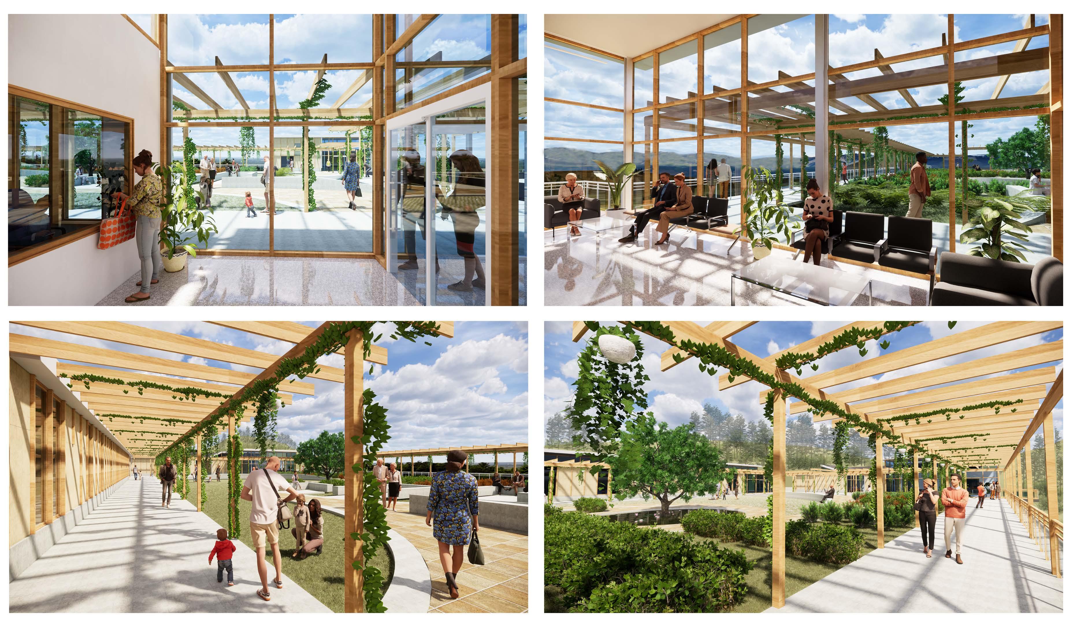

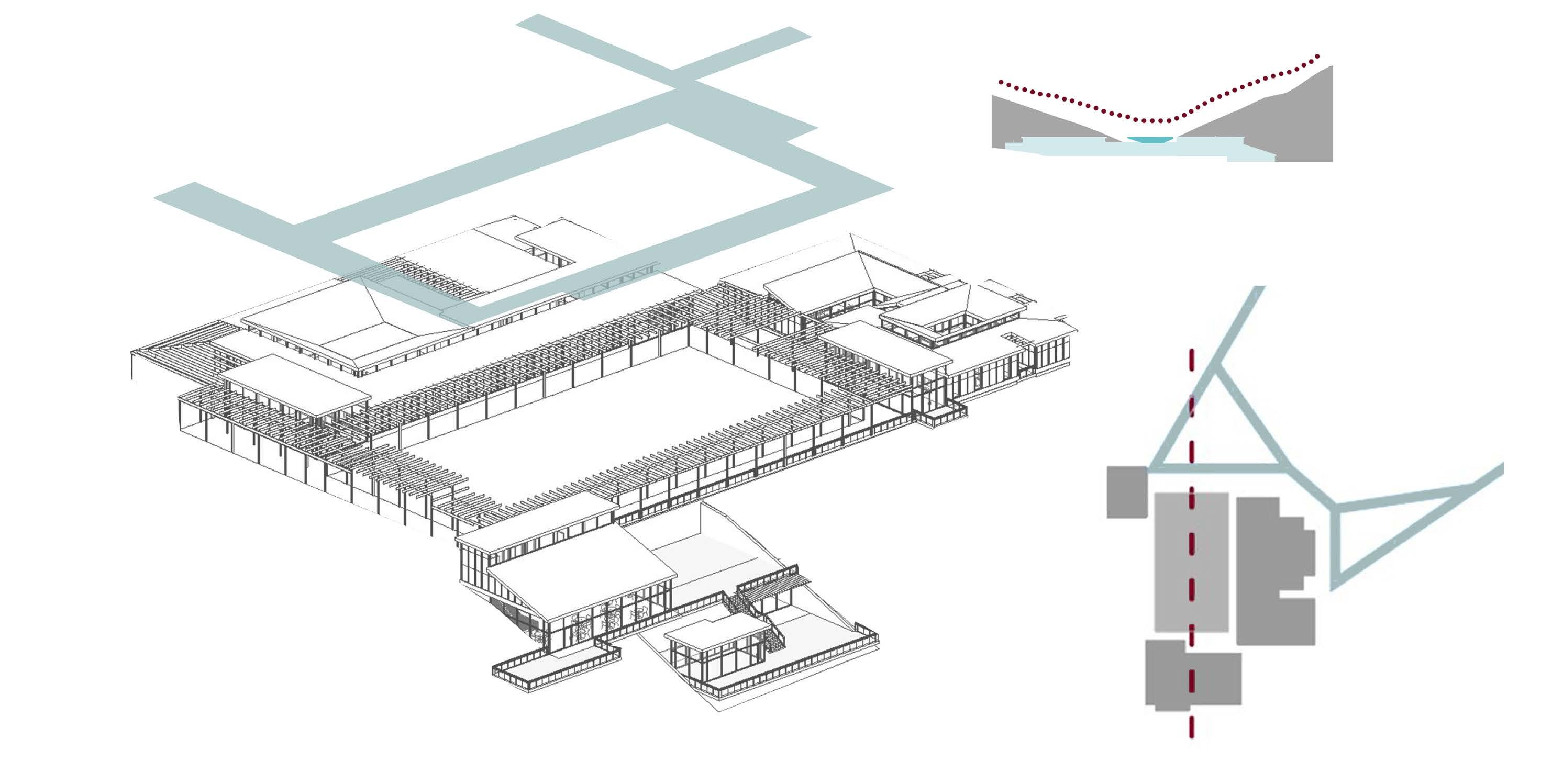
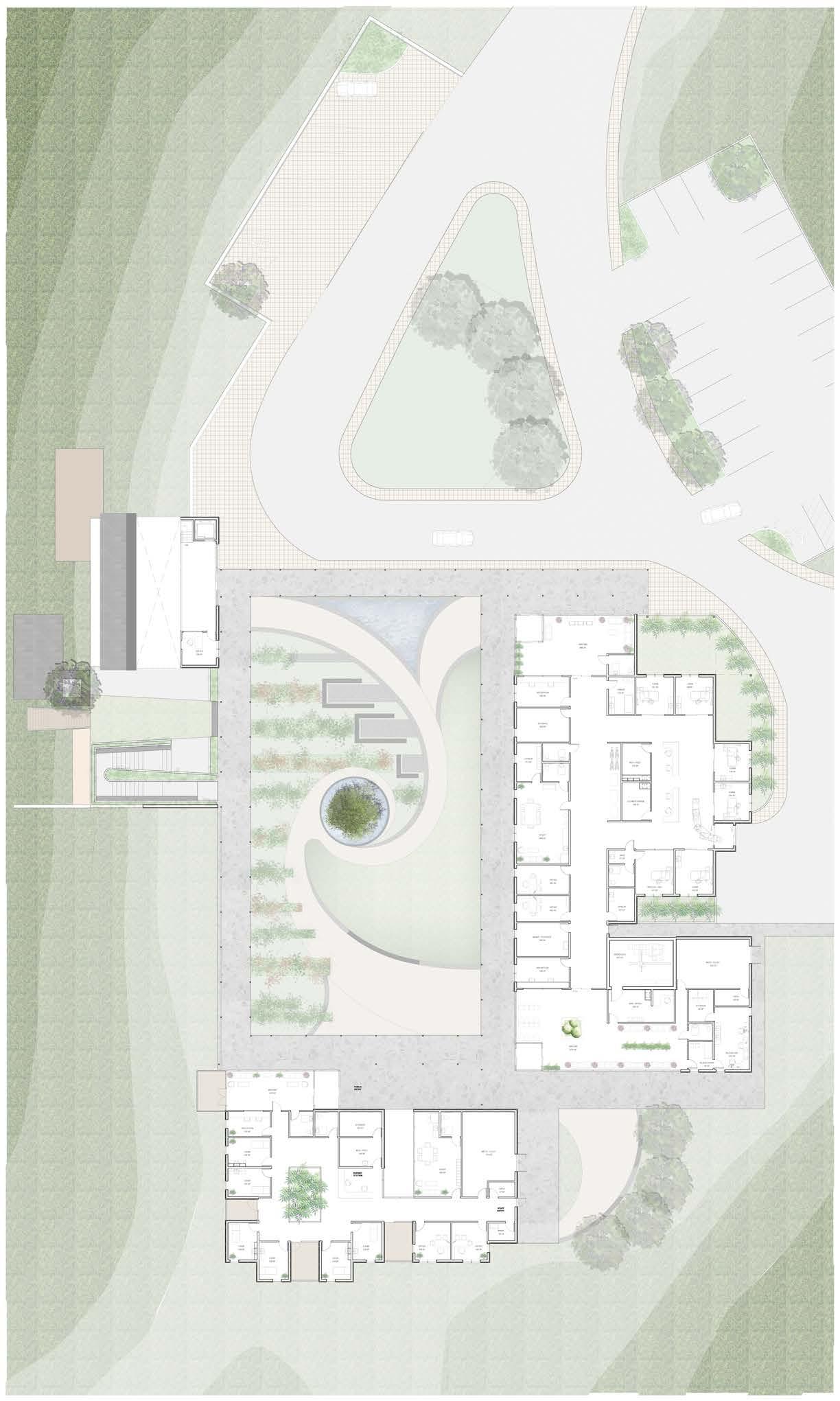
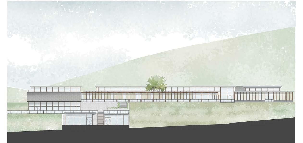
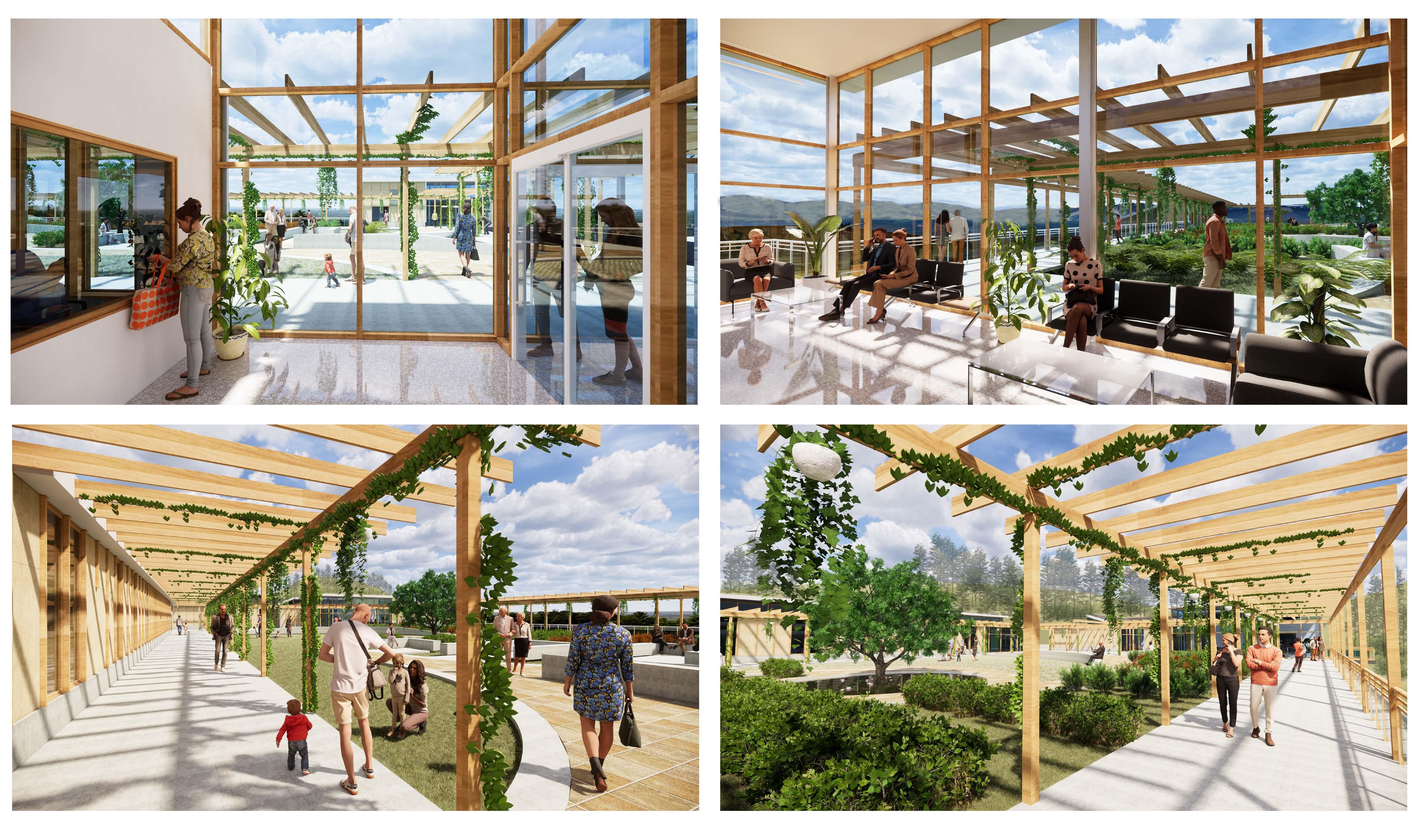
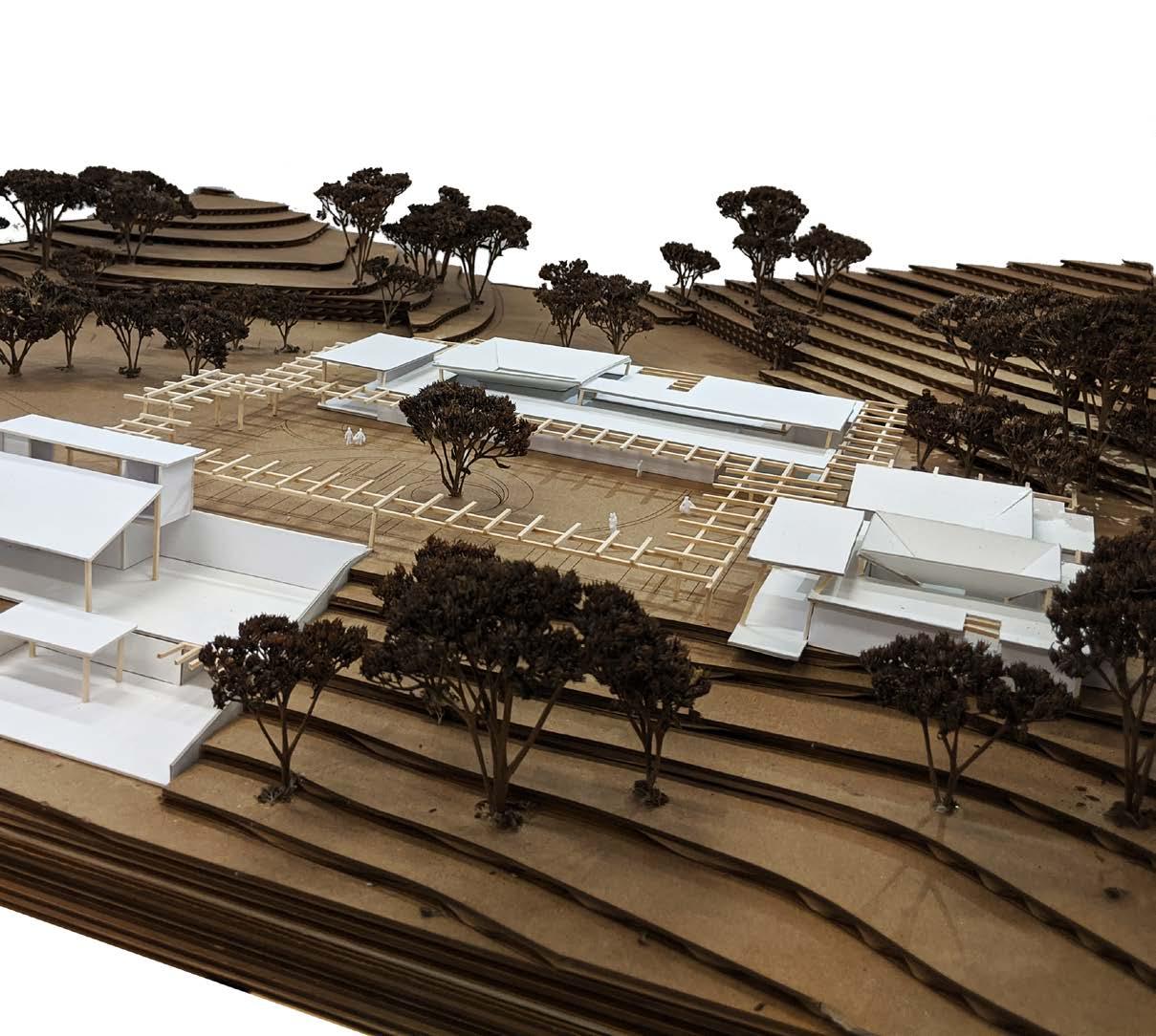
Our research-based approach to a healthcare campus focused on familiarity, wayfinding, access to greenspace and light, and participatory community design. Familiarity came through in our form and materiality, producing a single-story, aesthetically pleasing façade experienced all throughout the campus.
To allow for access to greenspace and light, we staggered the rectilinear geometry of our buildings in both plan and section, opening to courtyards and gardens. We also lifted our roof higher in public areas to allow for larger curtain walls or ribbon windows all throughout the buildings. Our final key design concept was that of giving back to the surrounding community by creating a community center and large landscape space.
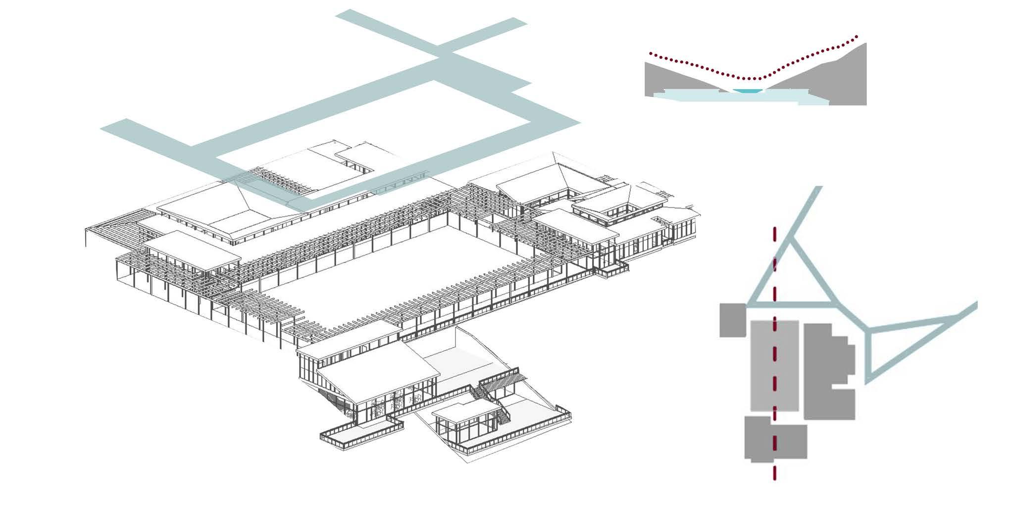
greenspace and sun study

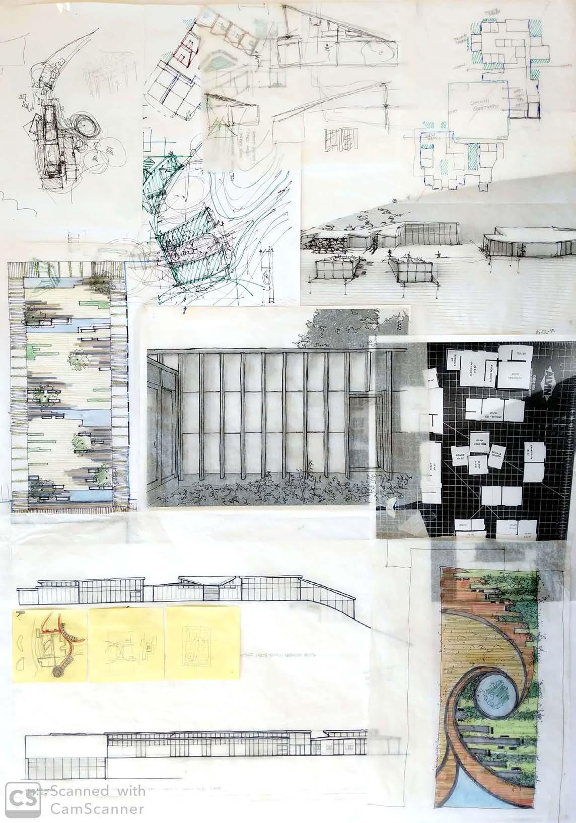
sketches
axis development roof profile vs. slope on site roof slope studies study


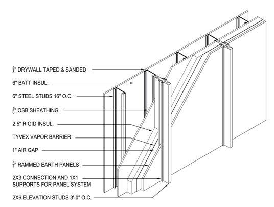
 facade assembly




IN SITU HOME
archon studio
spring 2020
professor david chasco
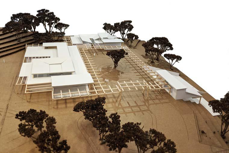
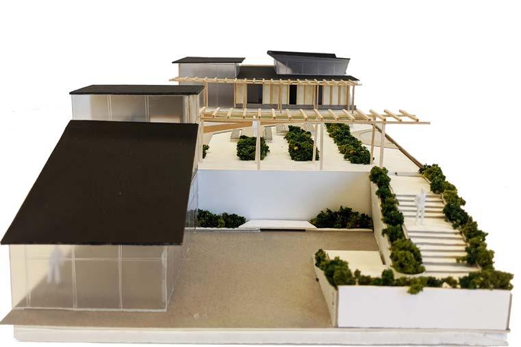
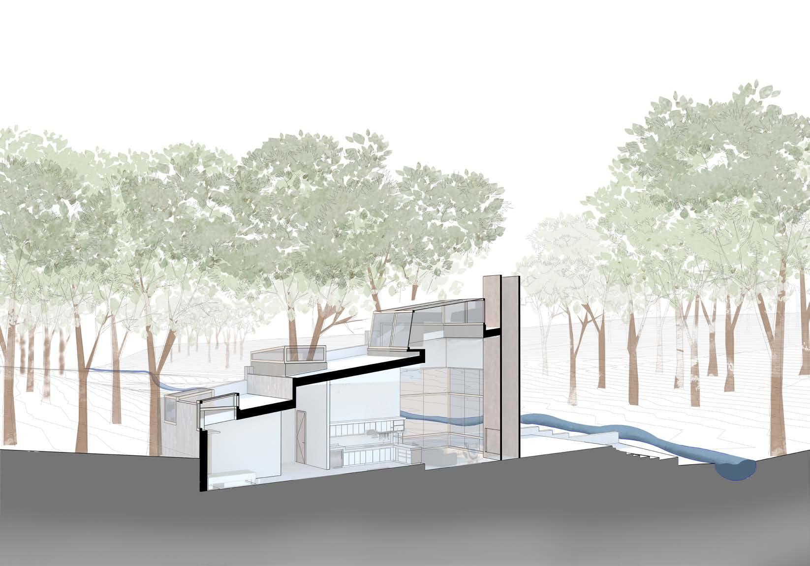
Humans today are tied up in the web of their urban environments and busy work life. We do not take a pause from the chaos to enjoy the little moments in life. The crisis we are facing in 2020 in a way has forced us to retrieve to our homes and spend time with our family. It has given us a chance to re-evaluate our priorities in life.
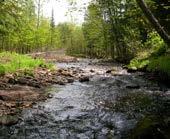
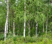
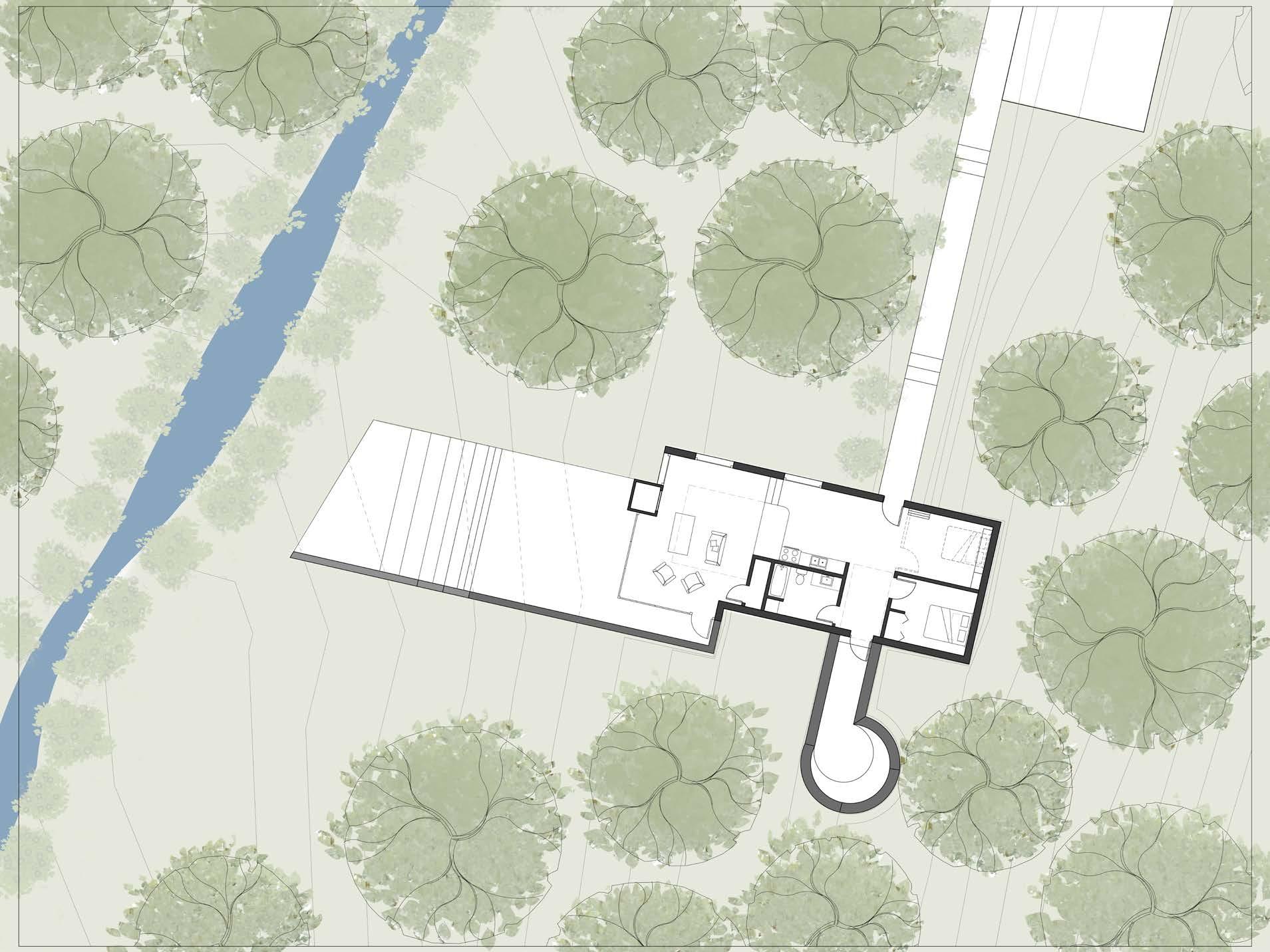
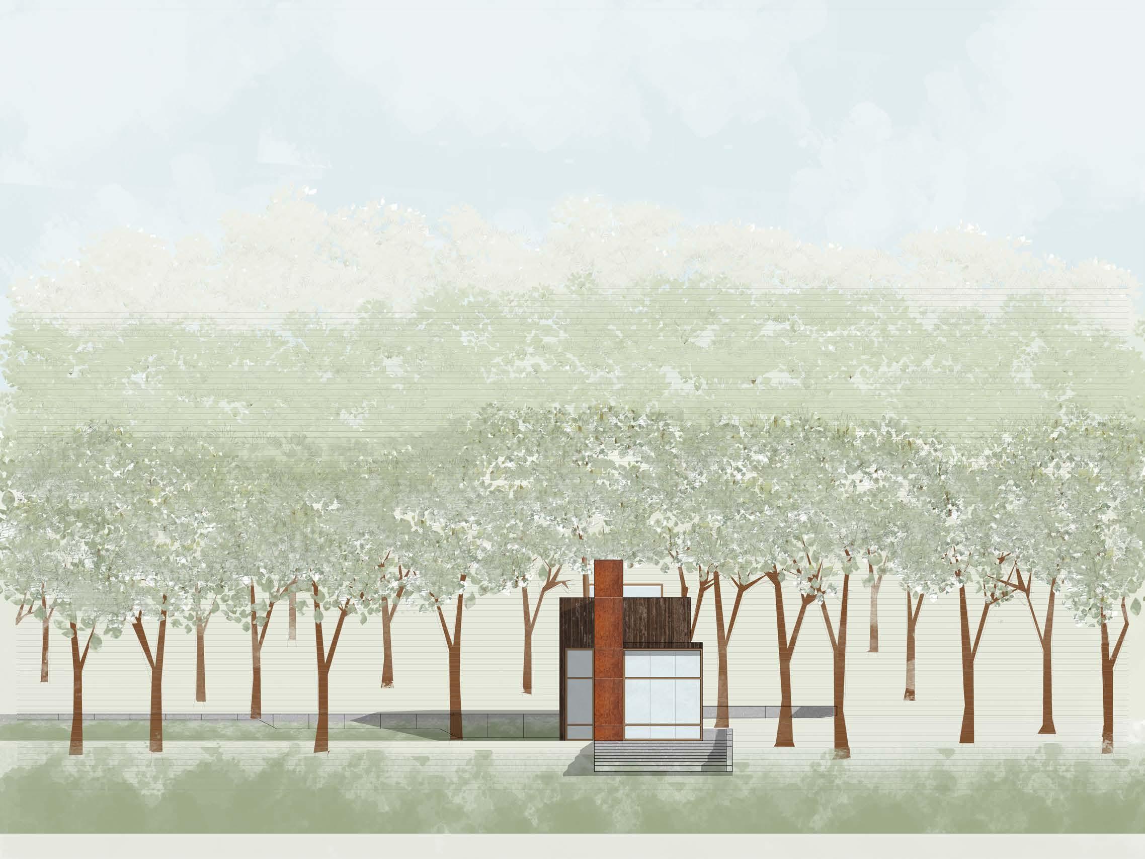
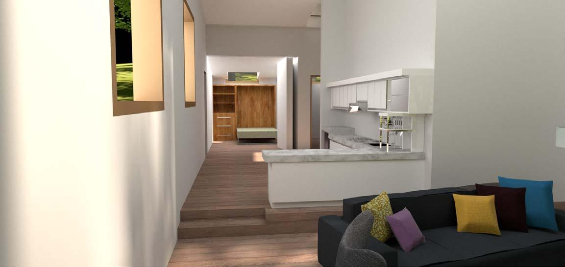
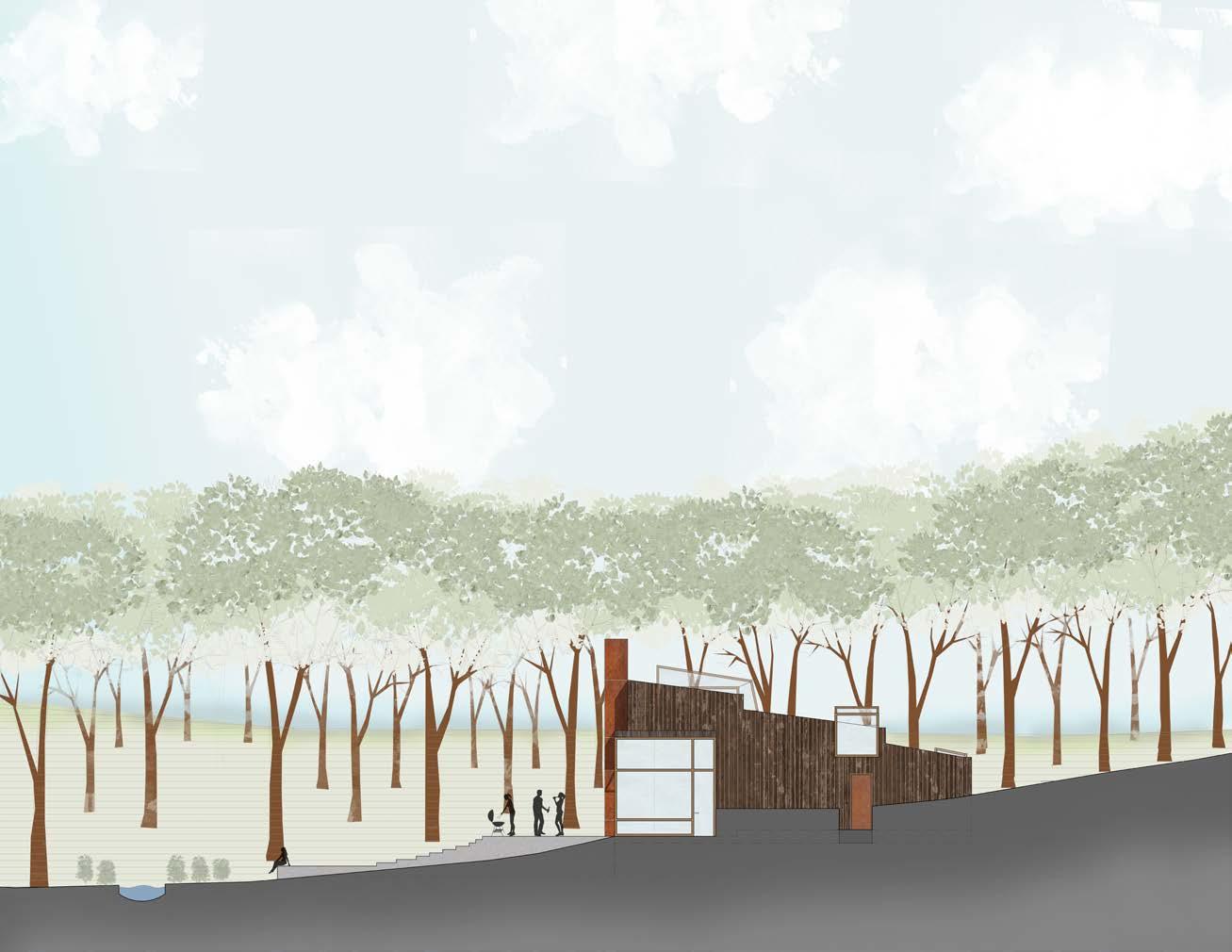
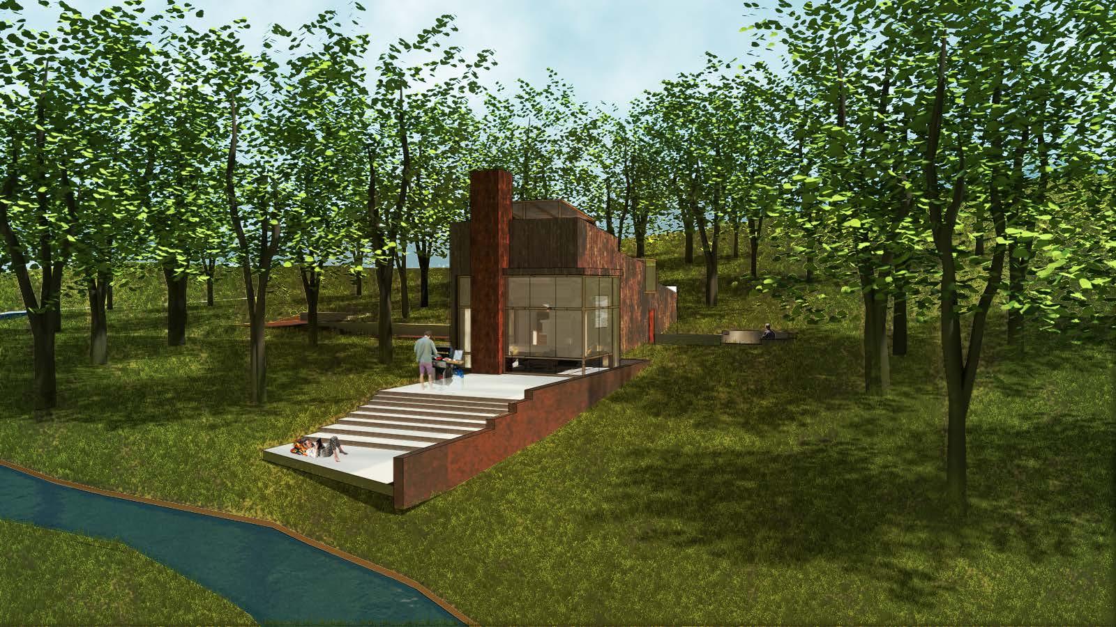
This house serves as a getaway place for a family. The idea is to disconnect from the city while being able to connect with each other and with nature. Tucked in amidst the forested area, the fenestrations and skylights bring in light while framing different views around the site. The skylights provide moments of surprise and are unique for giving the ability to look up the hill or the sky. An open floor plan creates both spaces for congregation and isolation. The linear geometry runs perpendicular to the creek and is extended out to a deck. A sunken garden is added to the side to give a secluded area for personal use. The house provides a moment to pause, relax, and reconnect.
05



 Scanned with CamScanner
Scanned with CamScanner
Scanned with CamScanner
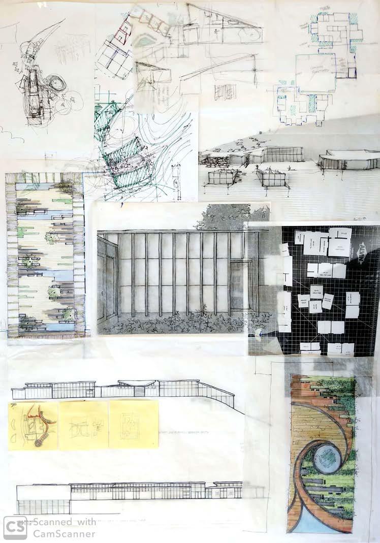
intial sketches
Scanned with CamScanner
massing + site integration
fenetration + views
building axis
roof line vs. topography zoning


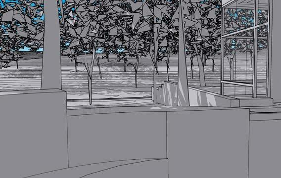 sunken garden views


06
TRANSPOSE
future of work
spring 2018
professor michael rogovin
first prize- future of work competition
This project was a part of a competition studio “future of work” organized by BHDP architecture. The goal of the competition was to imagine a problematic future and give our proposal as a solution. After some research on freelance and start up industries, I created the following future and proposal.
Future: It is the year 2030 and our world is changing as always. The major tech companies like Apple and Google, have gained a strong hold over the industrial sector. The year is also experiencing its greatest percentage of freelancers and small businesses than ever before. This new generation of workers strays away from the traditional workplace scenarios and wants to create its own framework for the workplace.
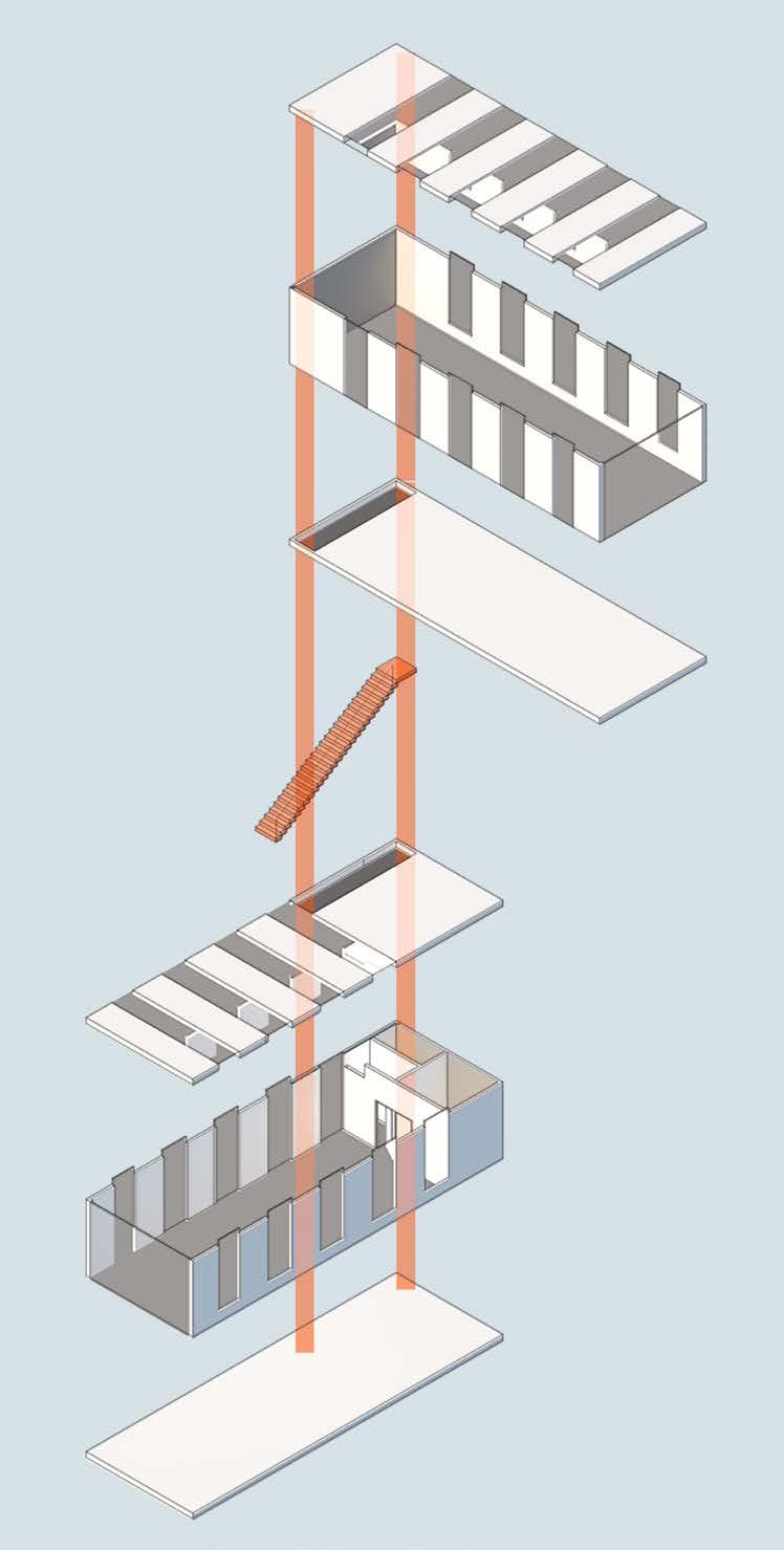
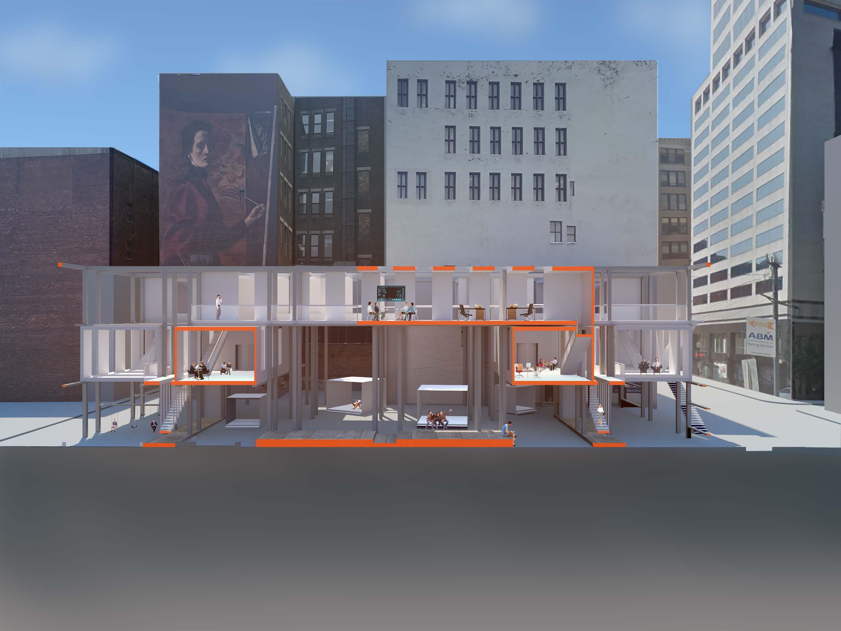
Proposal: Transpose provides a design solution for the growing freelance and small business population. The proposal is a matrix of pre-fabricated modular workplaces that are supported by a grid of steel structure. The image on the right is an 1/8 inch section model of the proposed design.
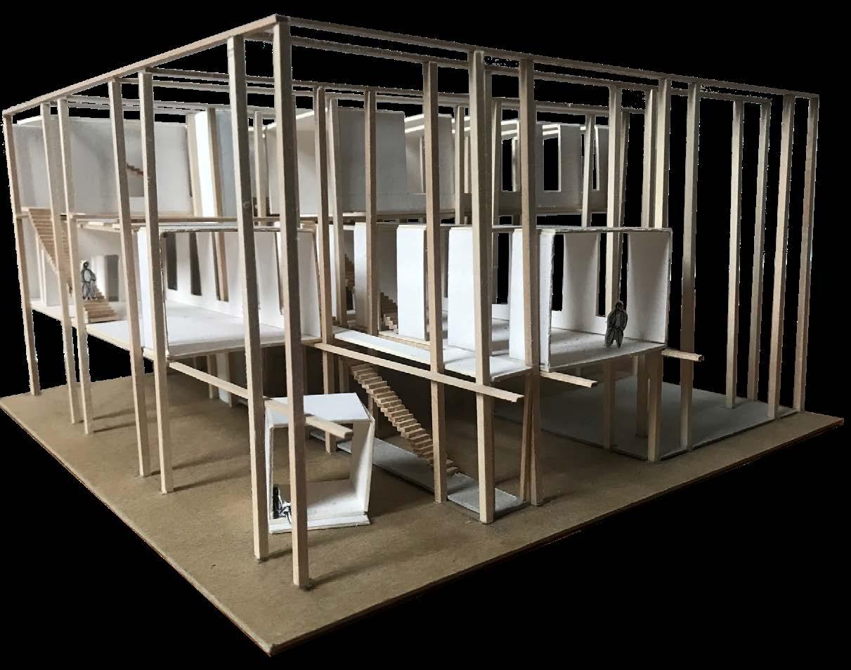
CONCEPTa low cost system that could support a small business while giving it the flexibility to grow and change at the same time.
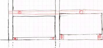
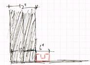
A 10’x10’x40’ prefabricated module that is insterted in a 10x10 steel grid that can be connected to each other vertically and horizontally. The floor plan can also be customized according to the user. All units elevated up a level create a public space at the ground level.
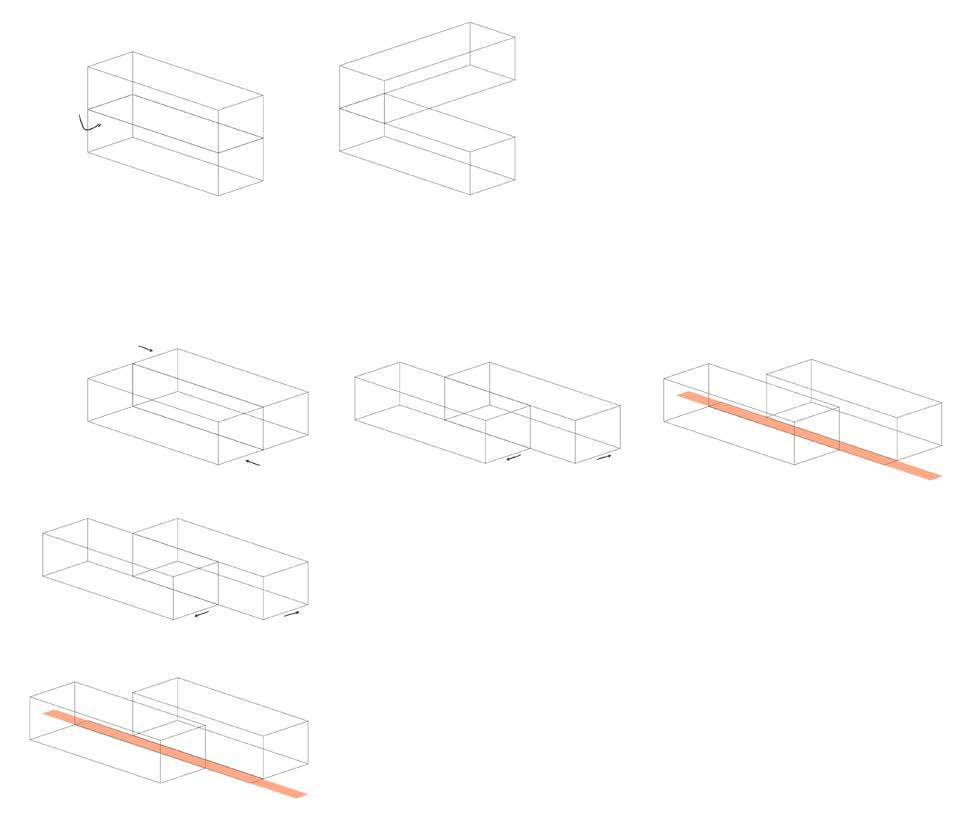



stacking
placement
study
vertical
horizontal
track system for modules vertical connection

grid
public level work levels

07
HOLZ UND STEIN
framework fall 2017
professor terry boling
team- christine anneken, kriti chaudhry, john garrison, anna kendrick, connor kramer, srimoyee sinha
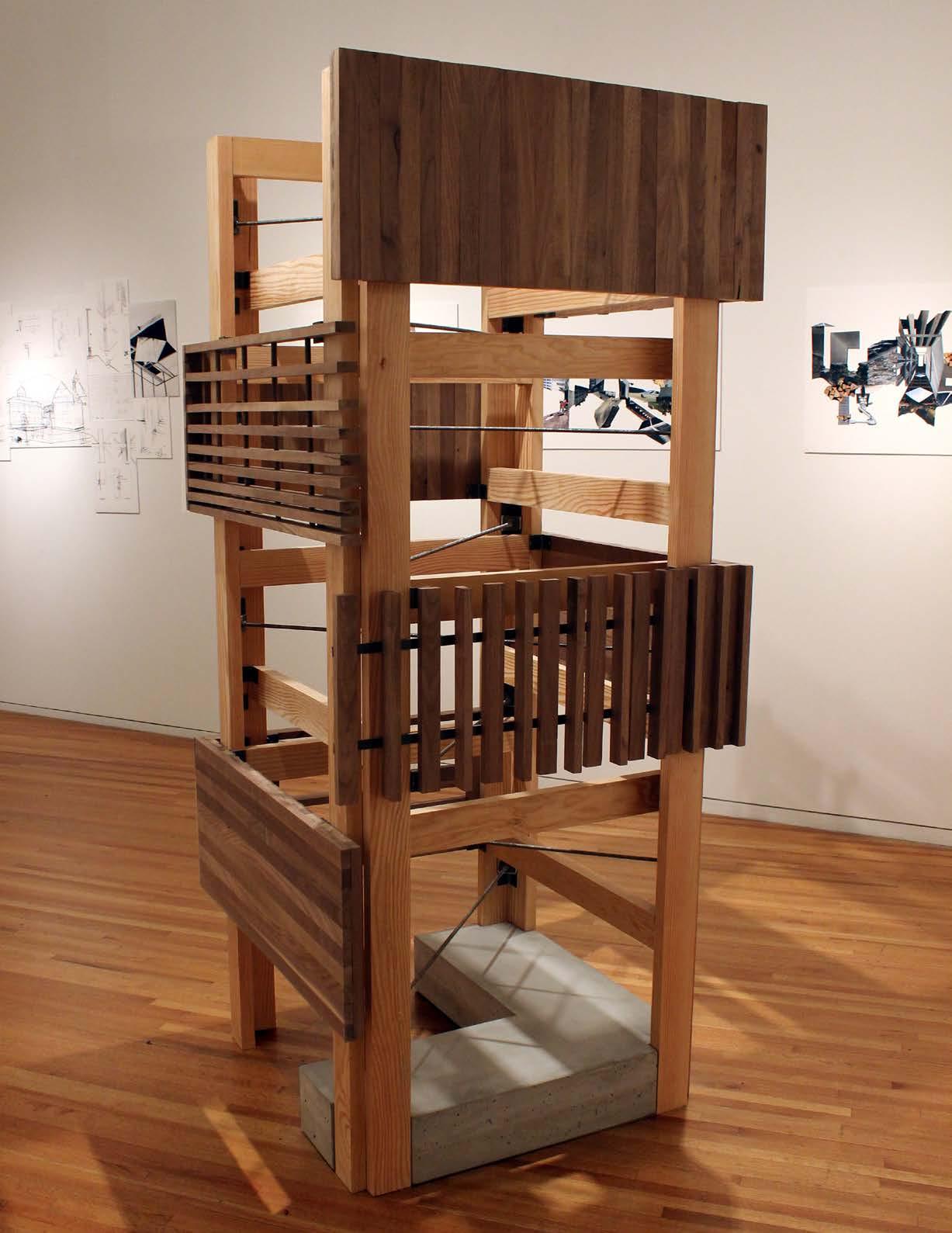
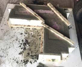
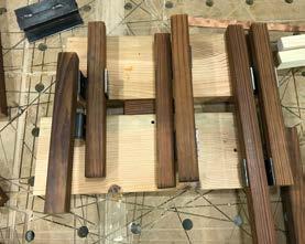
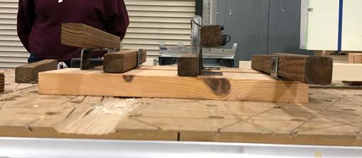
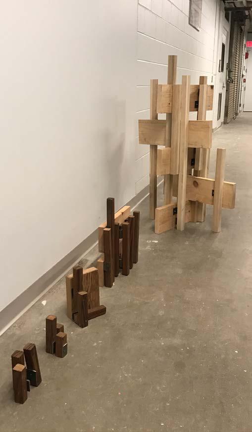
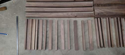
As part of a travel studio, a group of 18 students traveled to four different regions in Europe studying the design concepts and native architectural elements. After returning, we were tasked with curating and creating an exhibition. One that represented both the work we completed during the trip as well as newly built pieces. The goal was to craft a space that encapsulates the physical and emotional aspects of the travel while also exhibiting the architecture and construction that we studied. What followed was a human-scale expansive and fluid exploration of the techniques and attitutdes in architecture and construction prevelant in Switzerland. We started with an abstract collage using the photographs taken during the trip. From here we decided to tackle the design process using purely analog skills of model making and hand sketching.
contributions- concept design, structural connections and jointery techniques, screen design, and framework assembly
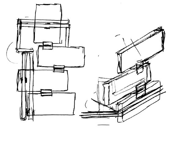
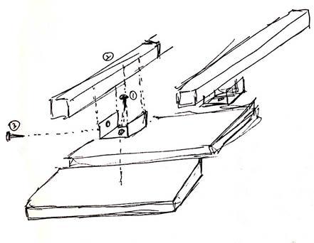
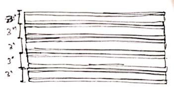
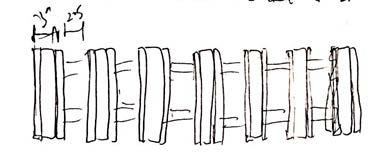
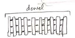
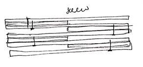
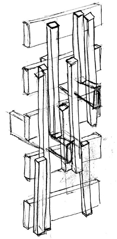
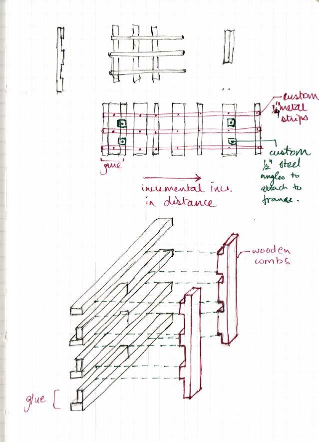
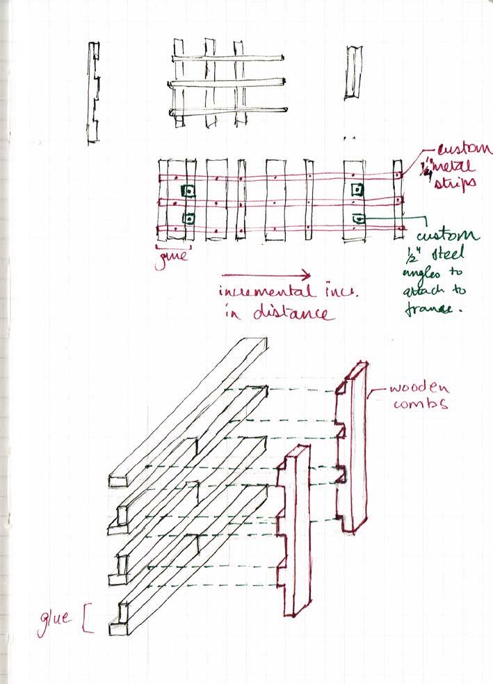
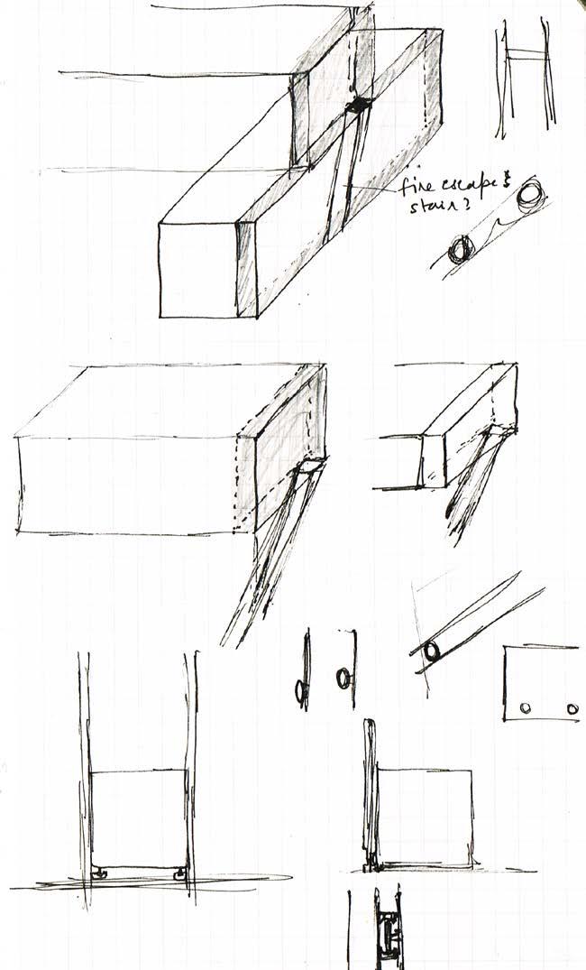
study sketches
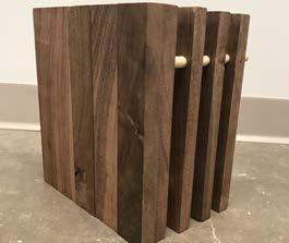
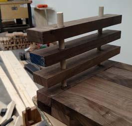
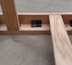
process models
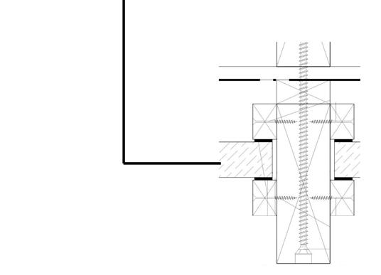
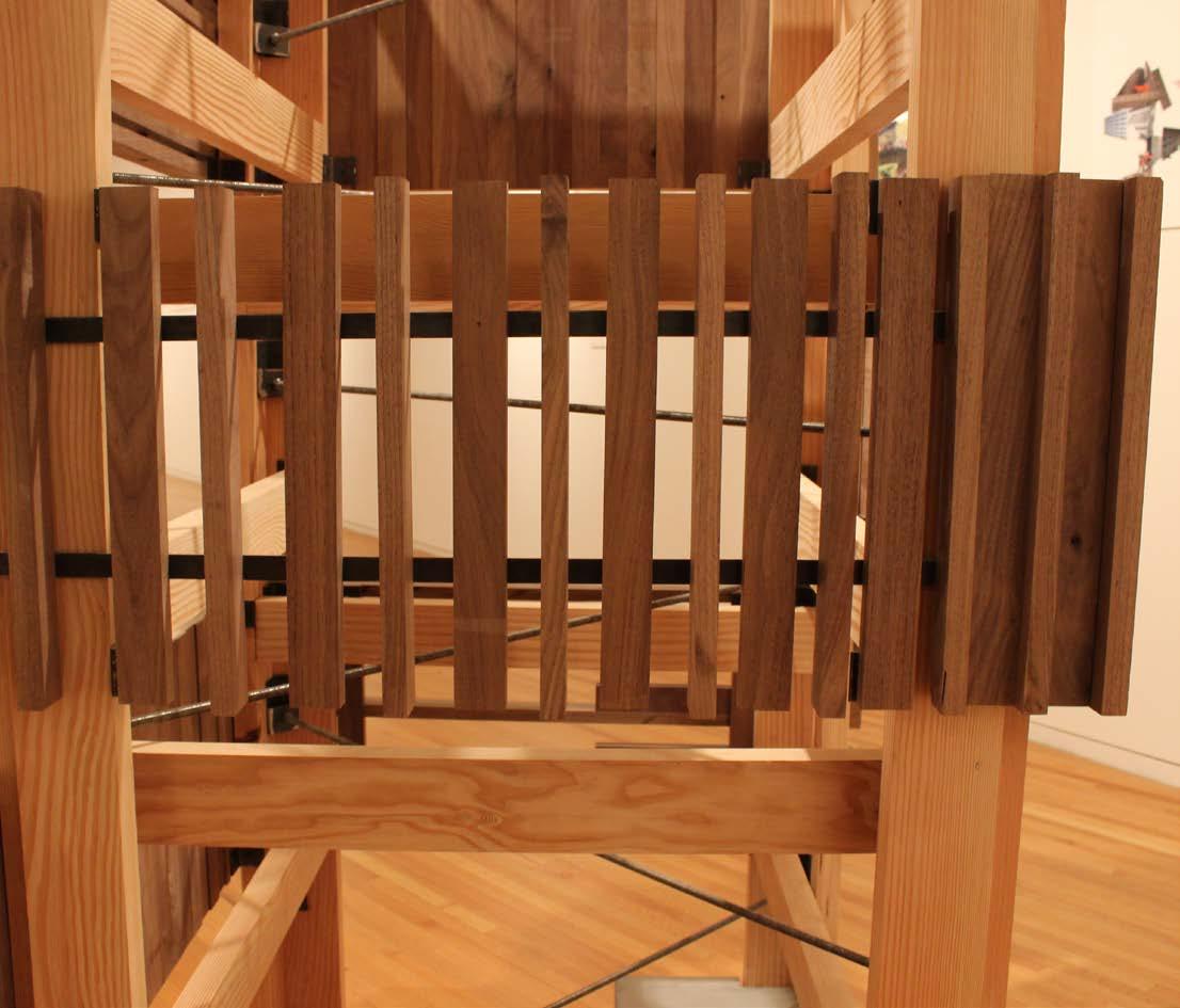
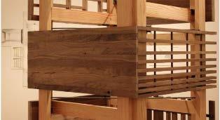
The final structure measured about 7’ tall and 3’ square. It consisted of a stud frame interior cladded with cross-laminated walnut panels and screens. The frame was reinforced with eight custom made steel tension rods and all the pieces are connected with1-1/2” steel clips. A two sided poured concrete base was used as foundation for the wooden structure to lay in.
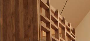
The framework consisted of four panels and perforated light screens. The screens were designed to articulate the layering and stacking of materials seen on building facades in Switzerland. The patterns were developed and connected using elements like metal straps, wooden combs, and wooden dowels. The CLT panels were coordinated to match the screens directionally and attached to the main structure using the same 1-1/2” steel clips. All pieces were reused after disassembly.



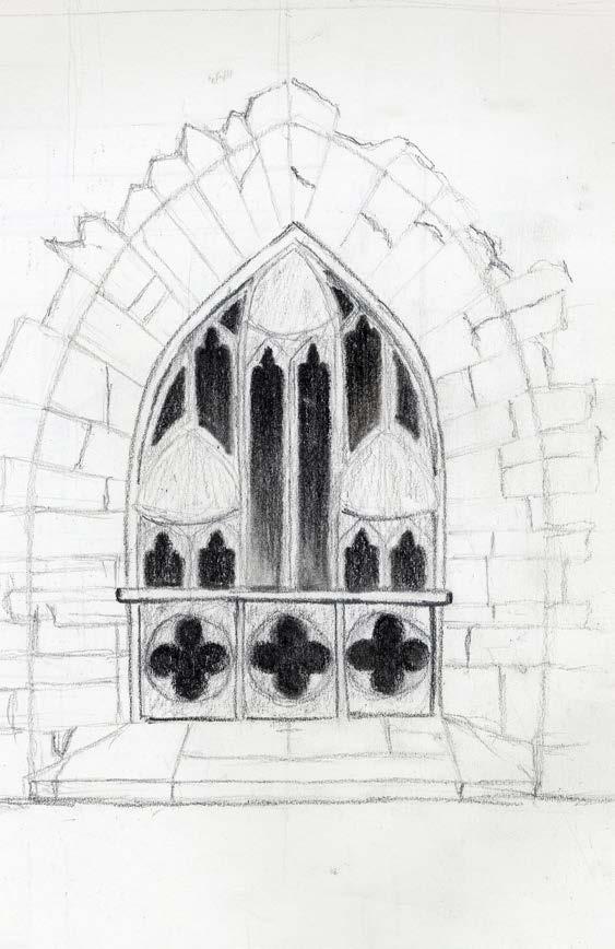
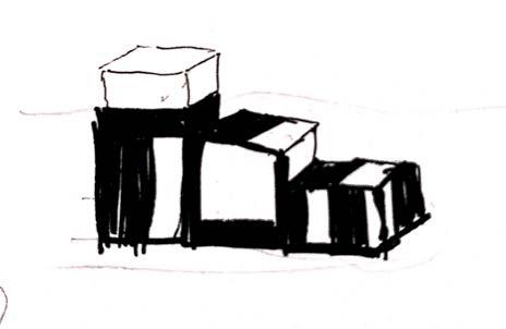
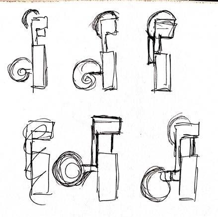
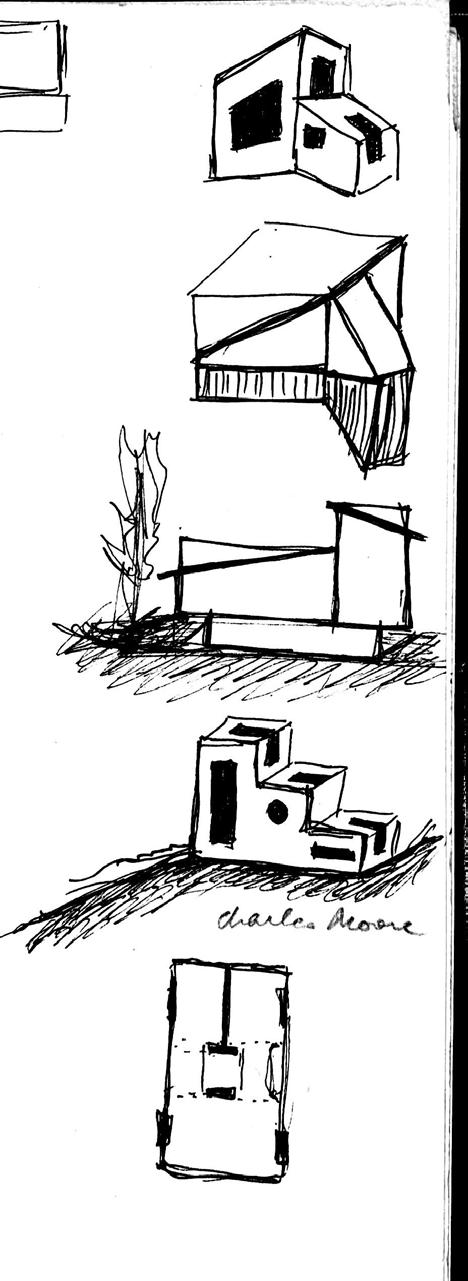
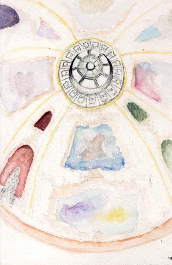
08 SKETCHES
kritichaudhry5@gmail.com
(513)-223-2743
KRITI CHAUDHRY
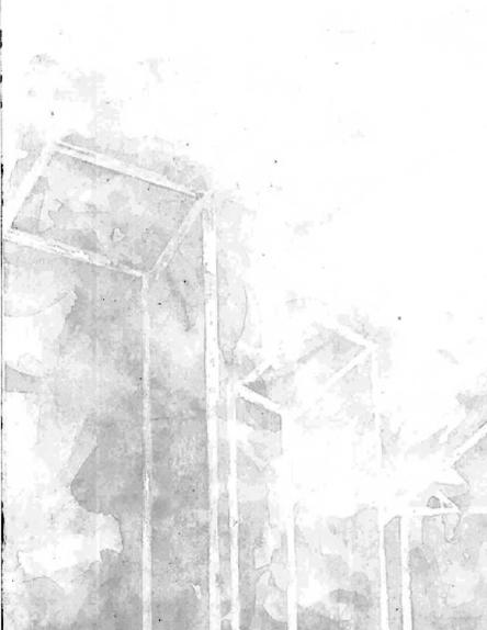


 New Health Sciences: Horizontal grain punctuated with vertical towers


 facade assembly


 Scanned with CamScanner
Scanned with CamScanner
Scanned with CamScanner


 sunken garden views


