
CK25-CK28 Crawler Excavators
Table of contents
This symbol means ATTENTION ! BECOME ALERT! YOUR SAFETY IS A IN VOL VED. The message that follows the symbol contains important Lll information about safety. Carefully read the message, Make sure you fully understand the causes of possible injury or death.
To prevent injury always follow the Waming, Caution and Danger notes in this section and throughout the manual.
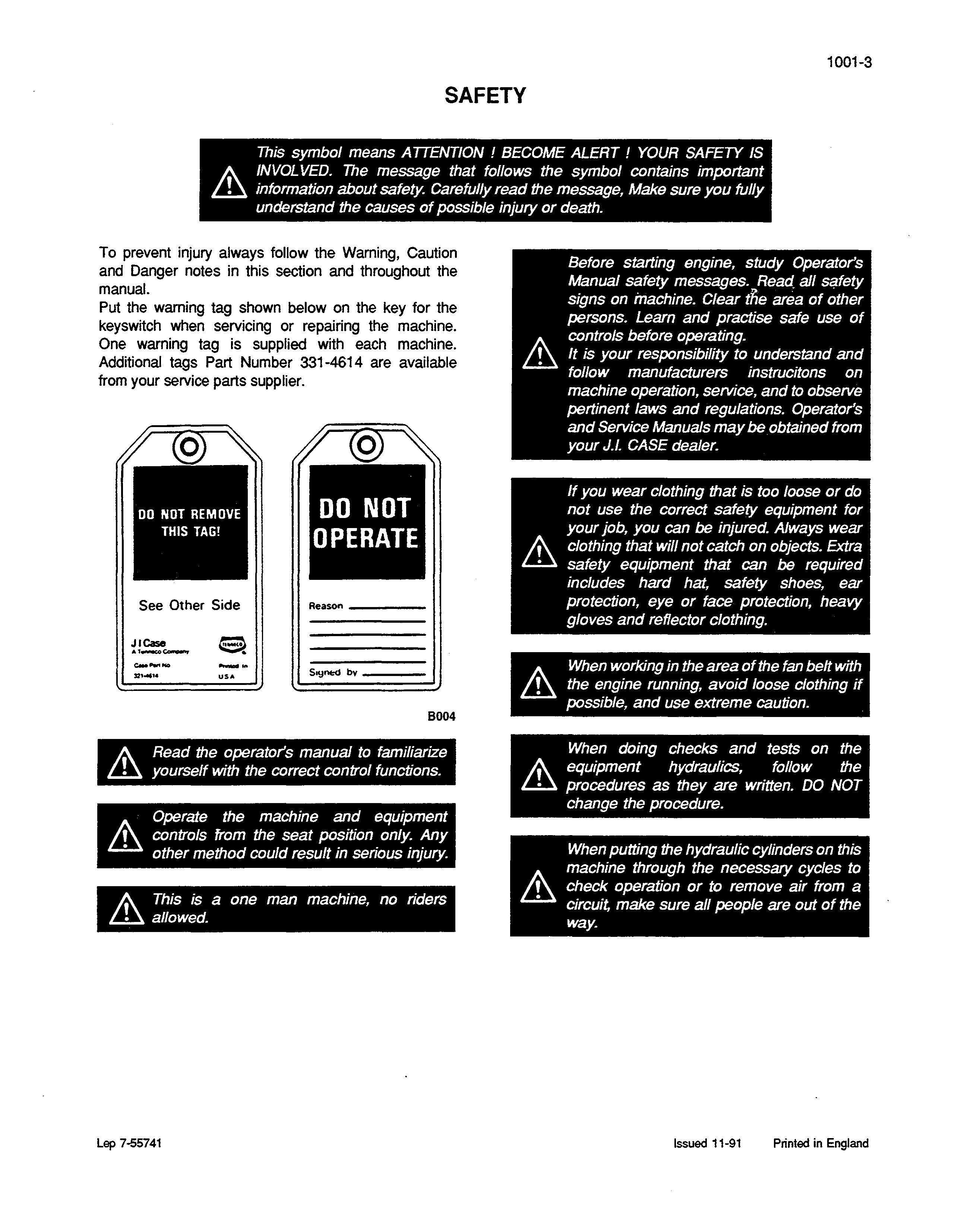
Put the waming tag shown below on the key for the keyswitch when servicing or repairing the machine. One warning tag is supplied with each machine. Additional tags Part Number 331-4614 are available from your service parts supplier.
8004
A Read the operator's manual to familiarize yourself with the correct control functions.
Operate the machine and equipment &. controls from the seat position only. Any other method could result in serious injury.
A This is a one man machine, no riders allowed.
When working in the area of the fan belt with Lll the engine running, avoid loose clothing if poSSible, and use extreme caution.
When doing checks and tests on the A equipment hydraulics, follow the Lll procedures as they are written. DO NOT change the procedure.
When putting the hydraulic cylinders on this machine through the necessary cycles to check operation or to remove air from a Circuit, make sure all people are out of the way.
1001-4
I:\. Use insulated gloves or mittens when working with hot parts.
I:\. Lower all attachments to the ground or use stands to safety support the attachments before you do any maintenance or service.
When servicing or repairing the machine. Keep the shop floor and operator's compartment and steps free of oil, water, grease, tools, etc. Use an oil absorbing material and or shop cloths as required. Use safe practices at all times.
Some components of this machine are very I:\. heavy. Use suitable lifting equipment or Lll additional help as instructed in this Service Manual.
Batteries contain acid and explosive gas. Explosions can result from sparks, flames or I:\. wrong cable connections. To connect the ill jumper cables correctly to the battery of this machine see the Operator's Manual. Failure to follow these instructions can cause serious injury or death.
Use suitable floor (service) jacks or chain
I:\. hoist to raise wheels or tracks off the floor. Always block machine in place with suitable safety stands.
GENERAL INFORMATION
CLEANING
Clean all metal components, except bearings, with steam or white spirit. Do not use caustic soda when steam-cleaning. After cleaning, dry and oil the components. Clean oil lines with compressed air. Clean bearings in kerosene, dry them completely and oil them.
INSPECTIONS
Carefully examine all disassembled components. Replace all parts showing signs of wear or damage. Light scores and scratches can be removed by honing or with a buffing compound. Fast, abnormal wear of components can be avoided by careful examination and early detection of wear and pitting.
BEARINGS
Check that bearings run freely. Replace bearings that show signs of too much play or seizing. Clean bearings in a good solvent or kerosene and allow them to dry naturally. DO NOT DRY BEARINGS WITH COMPRESSED AIR.
NEEDLE BEARINGS
Before installing needle bearings in their housing, remove any metal edges inside or around the housing. When installing bearings with a hydraulic press, grease the inside and the outside' of the bearing with petroleum jelly.
GEARS
Check all gears for signs of damage or wear. Replace damaged or worn gears.
SEAL RINGS, 0 RINGS AND FLAT SEALS
Always install new seal rings, O-rings and flat seals, if removed. Lubricate seal rings and O-rings with petroleum jelly.
SHAFTS
Check all shafts showing signs of damage or wear. Check particularly to make sure that any surface of the shaft in contact with bearings or seal rings is not damaged.
SERVICE PARTS
Always use genuine CASE service parts. To order service parts, see the Spare Parts Catalog and remember to give the correct reference of the necessary CASE part. No warranty claims will be considered for failures involving parts which are not of CASE origin.
LUBRICATION
Never use oil or grease which is different from that specified in the Operator's Manual or the Service Manual. No warranty claims will be considered for failures due to the use of wrong oil or grease.
Removal and Installation
STEP 1
Park the machine on hard level ground. Lower the attachment to the ground. Release pressure in the hydraulic circuits and stop the engine.
STEP 2
Disconnect the battery, positive (+) terminal first.
NOTE: For Installation, install and tighten the negative ( -) terminal first.
STEP 3
Remove the Cab or Canopy, refer to Section 9004.
STEP 4 / /
STEPS
Remove the Hydraulic Oil Reservoir, refer to Section 8010.
STEP 6
Put a container with a capacity of at least 5 Litres under the radiator drain valve and drain the coolant.
NOTE: For Installation, install coolant to the correct level.
STEP 7
Remove the bolts (1) and the protector (2).
NOTE: For Installation, apply Loctite 271 to the bolts and tighten to a torque of:
M12 - 77 to 90 Nm
M16 - 166 to 197 Nm
Remove the hood mounting bolts (1) from the inside of the engine compartment.
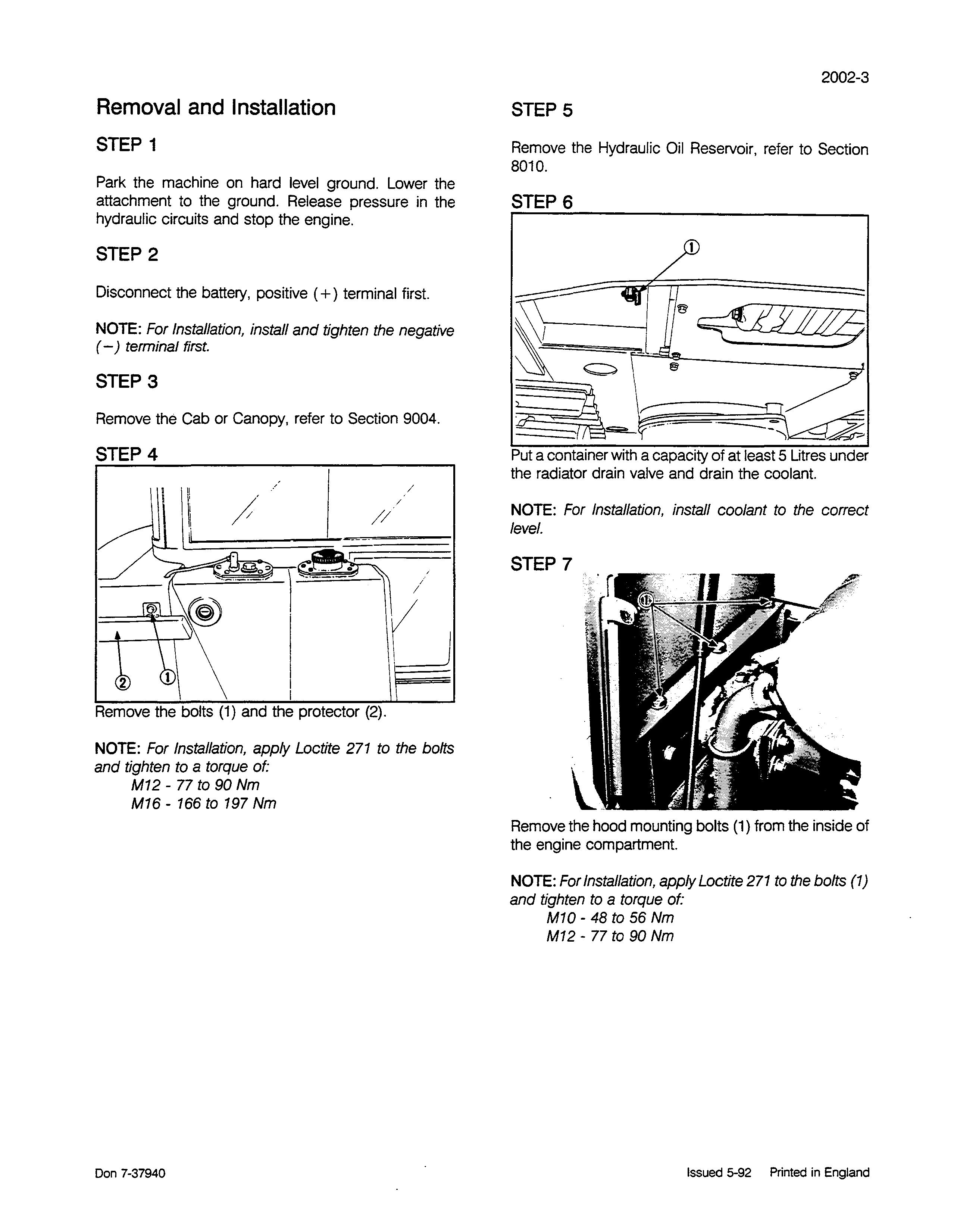
NOTE: For Installation, apply Loctite 271 to the bolts (1) and tighten to a torque of:
M10 - 48 to 56 Nm
M12 - 77 to 90 Nm
2002-4
STEP 8
STEP 10
Remove the battery and the fluid level sensor.
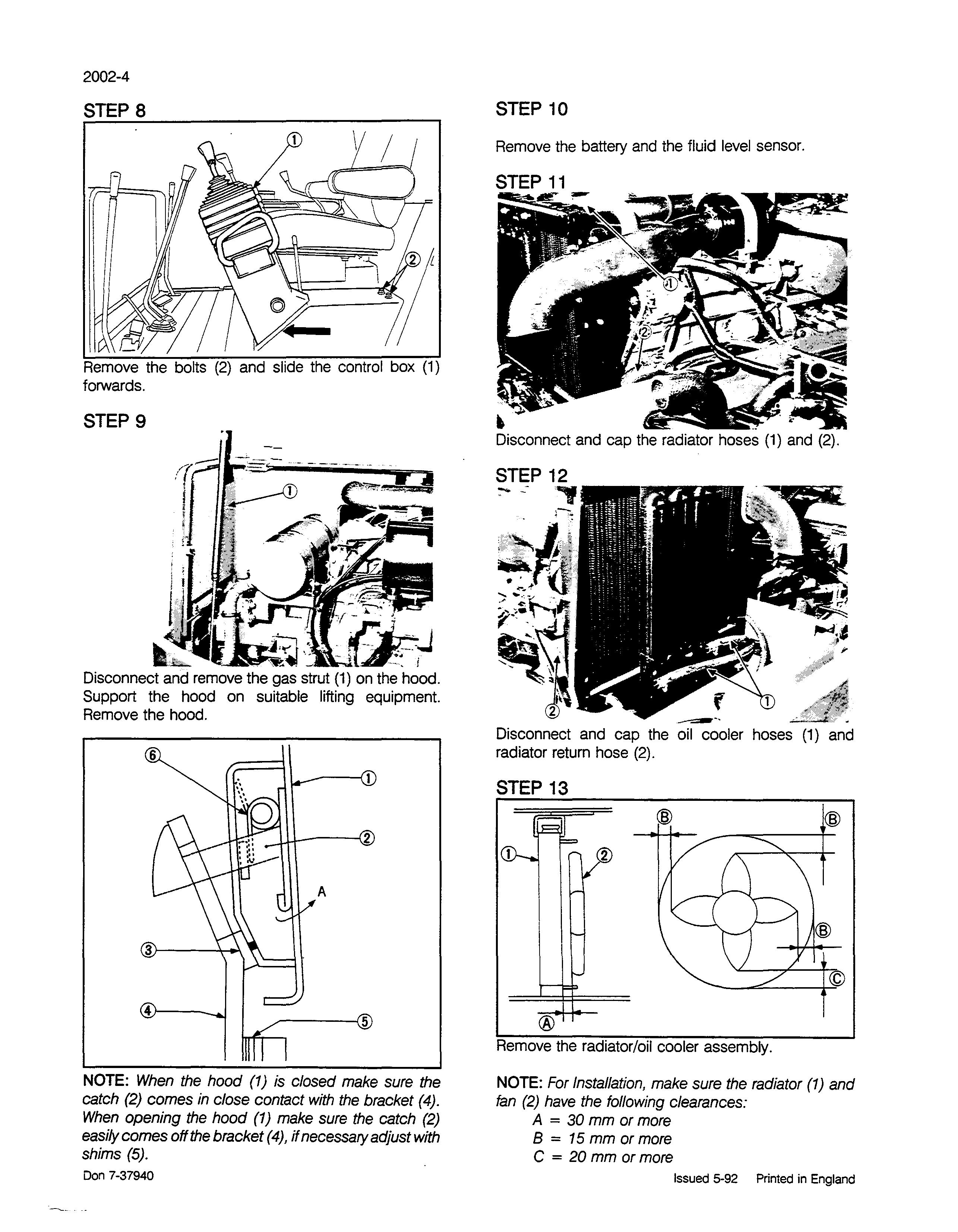
Remove the bolts (2) and slide the control box (1) forwards.
STEP
9
..h.. i
Disconnect and remove the gas strut (1) on the hood. Support the hood on suitable lifting equipment. Remove the hood.
Disconnect and cap the radiator hoses (1) and (2).
Disconnect and cap the oil cooler hoses (1) and radiator retum hose (2).
STEP 13 @ @
NOTE: When the hood (1) is closed make sure the catch (2) comes in close contact with the bracket (4). When opening the hood (1) make sure the catch (2) easily comes off the bracket (4), if necessary adjust with shims (5).
Don 7-37940
®
Remove the radiator/oil cooler assembly.
NOTE: For Installation, make sure the radiator (1) and fan (2) have the following clearances:
A = 30 mm or more
B = 15 mm or more
C = 20 mm or more
Disconnect the throttle cable (1), tachometer cable (2), fuel hose (3) and clamp (4).
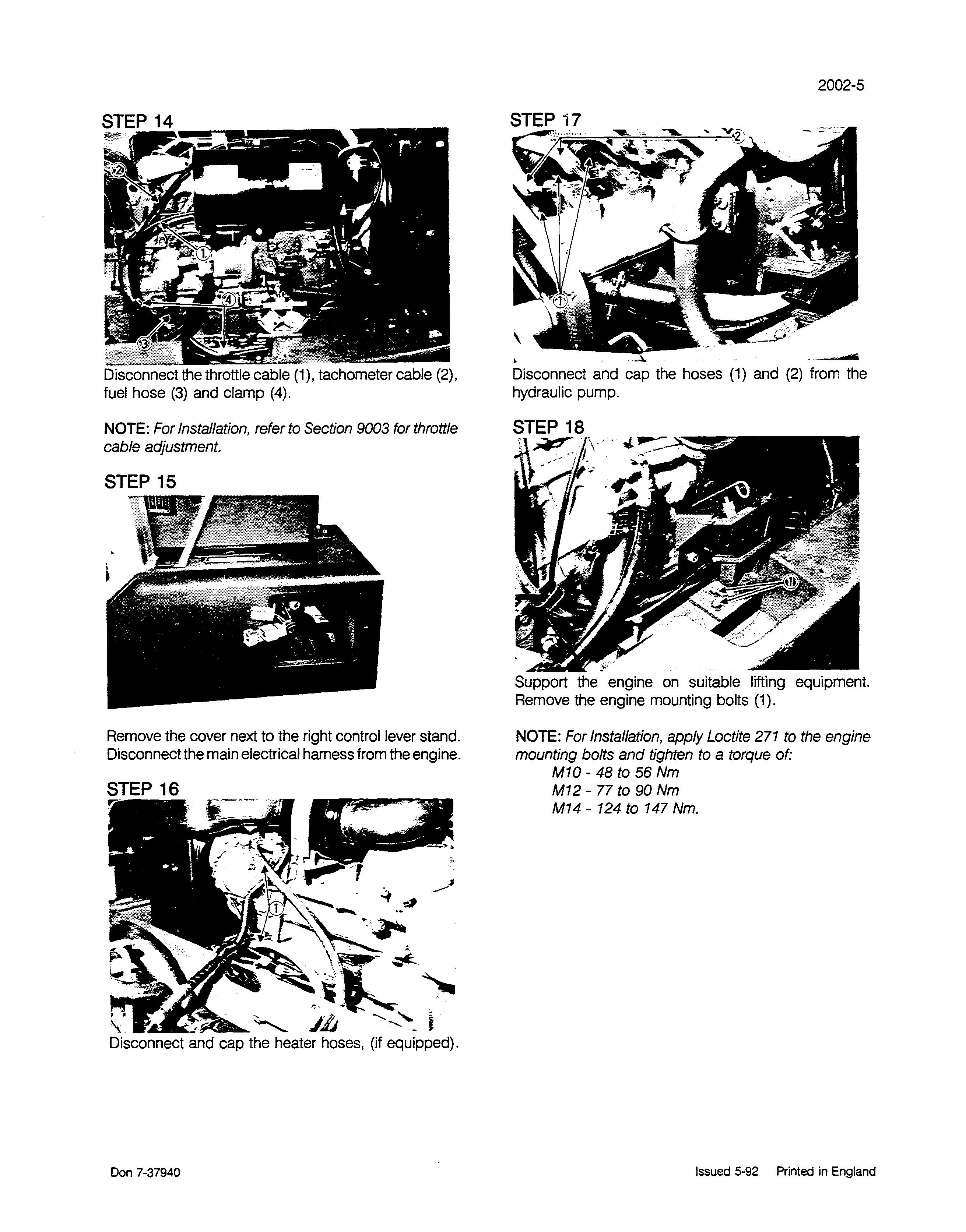
NOTE: For Installation, refer to Section 9003 for throttle cable adjustment.
STEP 15
Remove the cover next to the right control lever stand. Disconnectthe main electrical harness from the engine.
STEP 17
Disconnect and cap the heater hoses, (if equipped).
Disconnect and cap the hoses (1) and (2) from the hydraulic pump.
'"
Support the engine on suitable lifting equipment. Remove the engine mounting bolts (1).
NOTE: For Instal/ation, apply Loctite 271 to the engine mounting bolts and tighten to a torque of:
M10 - 48 to 56 Nm
M12 - 77 to 90 Nm
M14 - 124 to 147 Nm.
Carefully remove the engine from the machine.
NOTE: For Installation, follow the same procedure in reverse order. Open the heater valve, situated on top of the engine, to allow the coolant to circulate. Start and run the engine for appro>dmately 5 minutes. Stop the engine and check the coolant level, engine oil level and hydraulic oil level. Add coolant or oil if necessary.
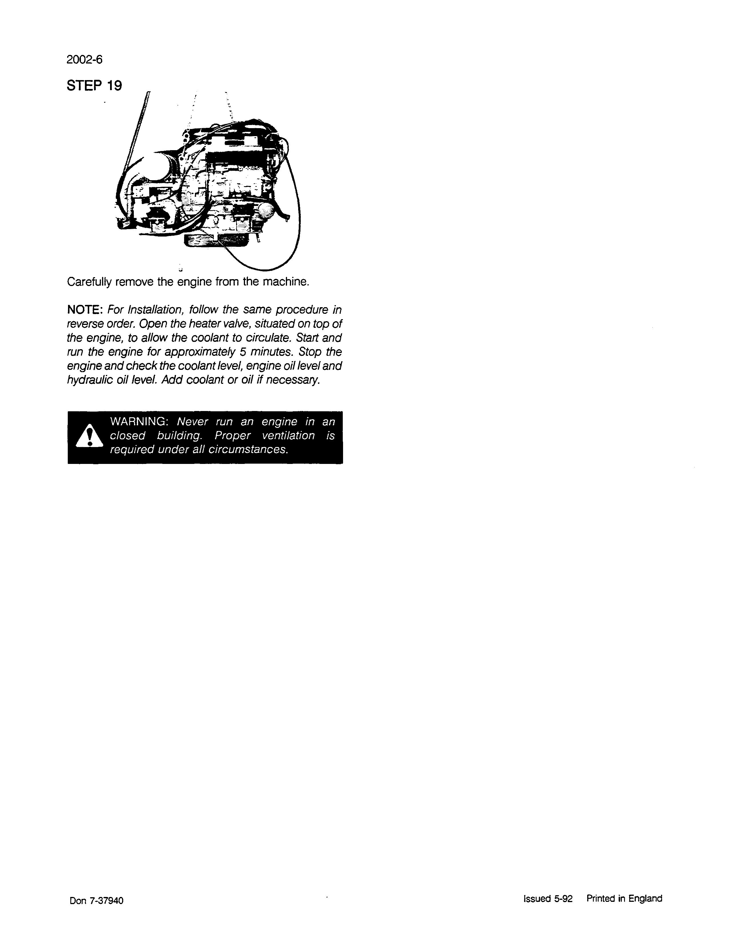
AWARNING: Never run an engine in an
closed building. Proper ventilation is required under all circumstances.
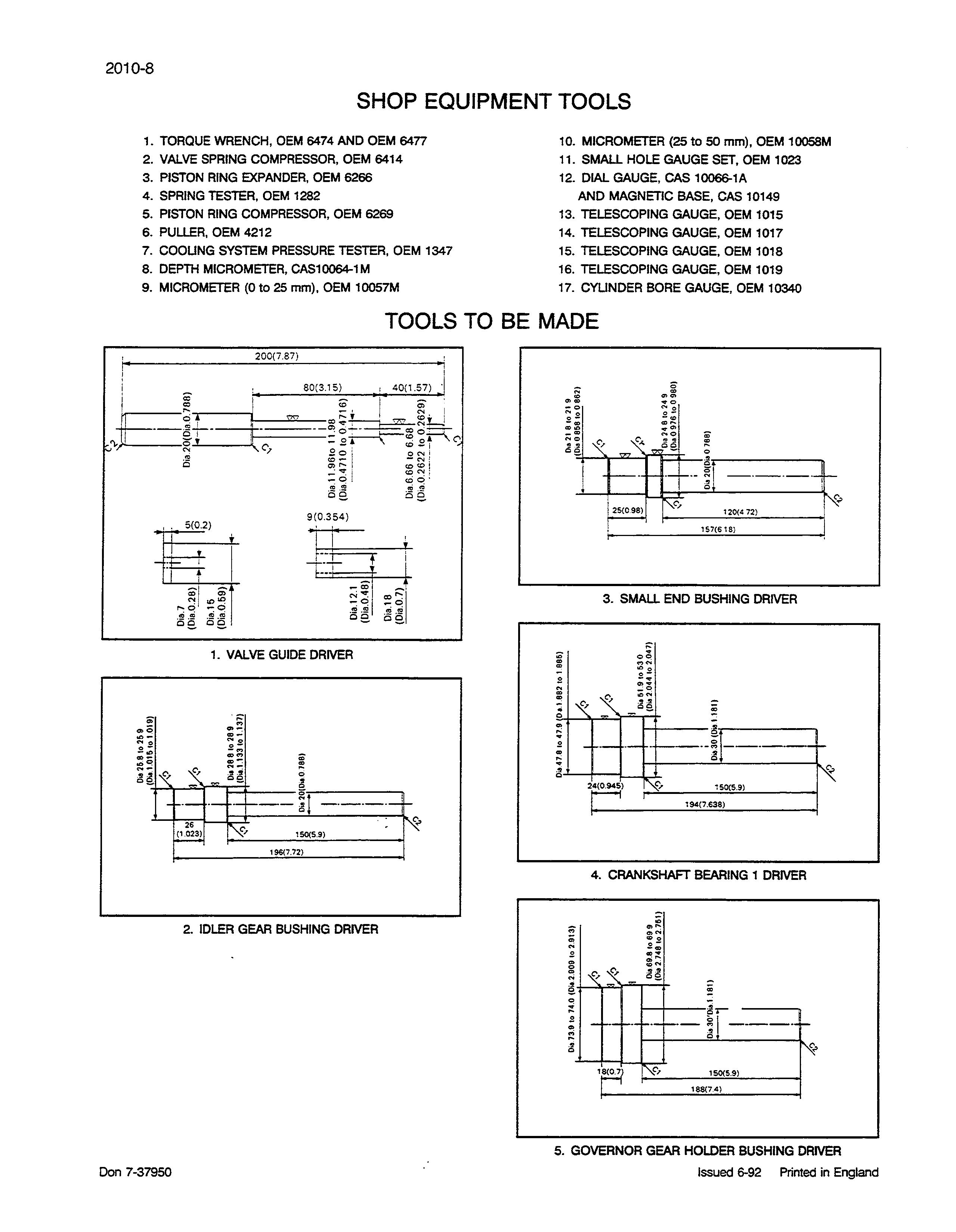
SHOP EQUIPMENT TOOLS
1. TORQUE WRENCH, OEM 6474 AND OEM 6477
2. VALVE SPRING COMPRESSOR, OEM 6414
3. PISTON RING EXPANDER, OEM 6266
10. MICROMETER (25 to 50 mm), OEM 10058M
11. SMAU HOLE GAUGE SET, OEM 1023
12. DIAL GAUGE, CAS l0066-1A
4. SPRING TESTER, OEM 1282 AND MAGNETIC BASE, CAS 10149
5. PISTON RING COMPRESSOR, OEM 6269 13. TELESCOPING GAUGE, OEM 1015
6. PULLER, OEM 4212 14. TELESCOPING GAUGE, OEM 1017
7. COOUNG SYSTEM PRESSURE TESTER, OEM 1347 15. TELESCOPING GAUGE, OEM 1018
TOOLS TO BE MADE
3. SMALL END BUSHING DRIVER
4. CRANKSHAFT BEARING 1 DRIVER
5. GOVERNOR GEAR HOLDER BUSHING DRIVER
Removal and Installation
STEP 1
CYLINDER HEAD STEPS

Remove the drain plug and drain the engine oil. Drain the coolant from the cylinder block.
STEP 2
Remove the air filter assembly and muffler.
NOTE: For Installation, install the muffler gasket with the steel side facing the muffler.
STEP 3
Remove the rocker cover retaining nuts. Remove the rocker cover (1) and discard the gasket.
NOTE: For Installation, install a new rocker cover gasket and tighten the retaining nuts to a torque of 6.9 to 8.8 Nm (5 to 6.5 Ib tt)
STEP 6
Remove the alternator (1), fan belt (2) and fan.
NOTE: For Installation, tighten the fan belt to 7 to 9 mm deflection at 98 N.
STEP 4
Remove and cap the fuel injection pipes. Remove the fuel overflow pipes. Remove the nozzle holder assemblies (1).
NOTE: For Installation, tighten the nozzle holder assemblies to a torque of 49 to 68.6 Nm (36 to 50.61b tt) and the fuel injection pipe nuts to a torque of 24.5 to 34.3 Nm (18 to 251b ft)
Don 7-37950
Remove the rocker shaft retaining nuts and remove the rocker shaft assembly. Remove the push rods.
NOTE: For Installation, tighten the rocker shatt retaining nuts to a torque of 21.6 to 26.5 Nm (16 to 19.51b tt)
Loosen the clamp and remove the coolant return pipe. Remove the cylinder head retaining bolts (14 to 1 for 3 cylinder engines) or (18 to 1 for 4 cylinder engines) and remove the cylinder head. Remove and discard the gasket.
NOTE: For Installation, install a new cylinder head gasket. Install and tighten the cylinder head bolts (1 to 14 for 3 cylinder engines)or (1 to 18 for 4 cylinder engines) to a torque of 63.7 to 68.6 Nm (47 to 511b ft).
NOTE: Check the torque of the cylinder head bolts after approximately 30 minutes running.
STEPS
Remove the tappets (1) from the crankcase. Put identification marks on the tappets (1) for installation.
NOTE: Coat the tappets (1) with clean engine oil before installation.
NOTE: For Installation, follow the same procedure in reverse order.
Don 7-37950
Disassembly and Assembly
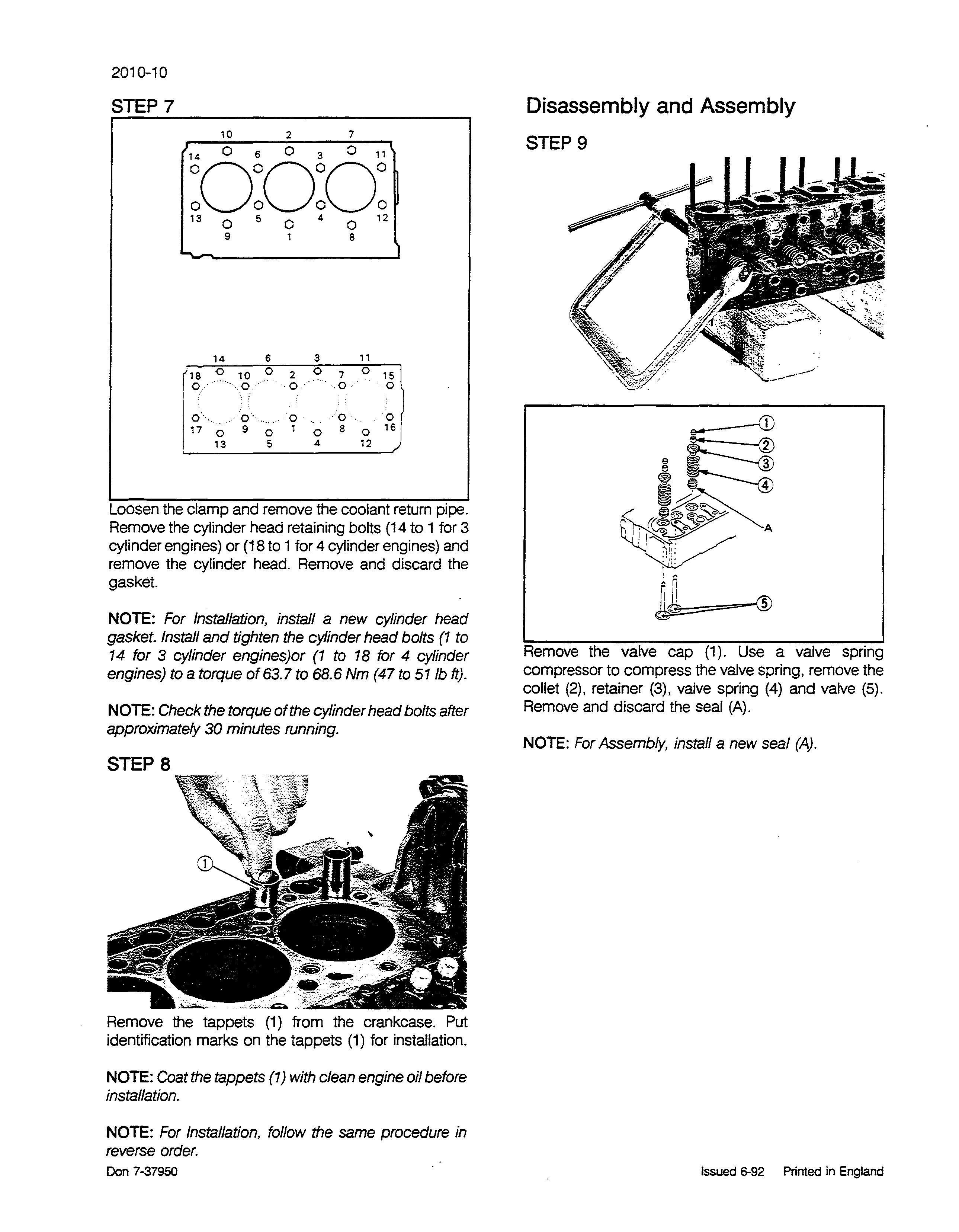
STEP 9
Remove the valve cap (1). Use a valve spring compressor to compress the valve spring, remove the collet (2), retainer (3), valve spring (4) and valve (5). Remove and discard the seal (A).
NOTE: For Assembly, install a new seal (A).


