
Previous Screen
Product: WHEEL LOADER
Model: 980C WHEEL LOADER 63X
Configuration: 980C Wheel Loader 63X06575-UP (MACHINE) POWERED BY 3406 Engine
Disassembly and Assembly
980C WHEEL LOADER POWER TRAIN
Front Drive Shaft
SMCS - 3253-11; 3253-12

Remove Front Drive Shaft
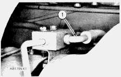
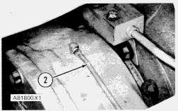
1. Remove four bolts (1) that hold the center drive shaft to the yoke. Pull drive shaft (2) clear of the yoke.

2. Remove six bolts and nuts (3) that hold the bearing cage and retainer to the frame.

3. Remove bolt (7) and retainer (6). Remove yoke (4) from the drive shaft.

4. Remove two bolts (8), and remove retainer (5) from the bearing cage.


5. Remove lip seal (9) from the retainer.
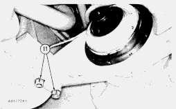
6. Install two 3/8"-16 NC forcing screws (11) in the bearing cage. Remove bearing cage (10) and bearing from the machine.
7. Remove O-ring seal (12) from the bearing cage.
8. Use tooling (A) and a press to remove the bearing from the cage.


9. Remove four bolts and nuts (13) that hold the universal joint to the yoke.

10. Remove front drive shaft (15) from the machine. The weight of the front drive shaft is 29 kg (64 lb.).
11. Remove universal joint (14) from the drive shaft.
Install Front Drive Shaft
1. Install universal joint (1) on the front drive shaft. Tighten the bolts to a torque of 135 ± 15 N·m (100 ± 11 lb.ft.).
2. Put front drive shaft (2) in position on the yoke of the front differential.
3. Install the bolts that hold the universal joint to the yoke. Tighten the bolts to a torque of 135 ± 15 N·m (100 ± 11 lb.ft.).


 4. Use tooling (A) and a press to install the bearing in the cage.
5. Install O-ring seal (3) on the bearing cage. Put a small amount of 1P808 General Purpose Lubricant on the O-ring seal.
6. Put bearing cage (4) in position in the frame. Make sure the opening (slot) (5) in the bearing cage is toward the top as shown.
7. Install the lip seal in the retainer with tooling (A). Install the seal with the lip toward the front of the retainer. Put a small amount of 1P808 General Purpose Lubricant on the lip of the seal.
4. Use tooling (A) and a press to install the bearing in the cage.
5. Install O-ring seal (3) on the bearing cage. Put a small amount of 1P808 General Purpose Lubricant on the O-ring seal.
6. Put bearing cage (4) in position in the frame. Make sure the opening (slot) (5) in the bearing cage is toward the top as shown.
7. Install the lip seal in the retainer with tooling (A). Install the seal with the lip toward the front of the retainer. Put a small amount of 1P808 General Purpose Lubricant on the lip of the seal.
8. Install retainer (7) on the bearing cage. Make sure grease fitting (6) is in alignment with the opening (slot) in the bearing cage.
9. Put yoke (9) in position on the drive shaft.
10. Put a small amount of 1P808 General Purpose Lubricant on the O-ring seal. Install seal (8), retainer (10) and the bolt. Tighten the bolt to a torque of 470 ± 50 N·m (347 ± 37 lb.ft.).
11. Install the center drive shaft on the yoke. Tighten the bolts to a torque of 135 ± 15 N·m (100 ± 11 lb.ft.).


Remove Center Drive Shaft
1.
Remove four bolts (3). Disconnect center drive shaft (2) and universal joint (1) from the yoke.2. Remove four bolts (4). Remove center drive shaft group (2) from the machine. The weight of the center drive shaft group is 32 kg (71 lb.).
3. Remove universal joints (1) and (5) from the center drive shaft group.


Install Center Drive Shaft Group
1. Install universal joints (1) on the center drive shaft group. Tighten the bolts to a torque of 135 ± 15 N·m (100 ± 11 lb.ft.).
2. Put center drive shaft group (2) in position on the transfer gear yoke. Install the bolts that hold it. Tighten the bolts to a torque of 135 ± 15 N·m (100 ± 11 lb.ft.).
3. Connect center drive shaft group (2) to the yoke of the front drive shaft. Install the bolts that hold it. Tighten the bolts to a torque of 135 ± 15 N·m (100 ± 11 lb.ft.).
Previous Screen
Product: WHEEL LOADER
Model: 980C WHEEL LOADER 63X
Configuration: 980C Wheel Loader 63X06575-UP (MACHINE) POWERED BY 3406 Engine
Disassembly and Assembly
980C WHEEL LOADER POWER TRAIN
Rear Drive Shaft
SMCS - 3253-11; 3253-12
Remove Rear Drive Shaft
START BY:
a. remove power train guard
1. Remove eight bolts and nuts (1). Remove rear drive shaft (3) from the machine.


2. Remove universal joints (2) from the drive shaft.
Install
Rear Drive Shaft
1. Install universal joints (2) on the drive shaft. Tighten the bolts to a torque of 135 ± 15 N·m (100 ± 11 lb.ft.).
2. Put rear drive shaft (1) in position between the transfer gears and the rear differential. Install the bolts that hold it. Tighten the bolts to a torque of 135 ± 15 N·m (100 ± 11 lb.ft.).
END BY:
a. install power train guard
Copyright 1993 - 2022 Caterpillar Inc.
All Rights Reserved. Private Network For SIS Licensees.
Previous Screen
Product: WHEEL LOADER
Model: 980C WHEEL LOADER 63X
Configuration: 980C Wheel Loader 63X06575-UP (MACHINE) POWERED BY 3406 Engine
Disassembly and Assembly
980C WHEEL LOADER POWER TRAIN
Front Axle Housing


SMCS - 3260-11; 3260-12
Remove Front Axle Housing
START BY:
a. remove front tires and rims
b. remove front drive shaft
3. Remove eight nuts (2) and the washers that hold the axle housing to the frame. Remove front axle housing (3) from the machine. The weight of the front axle housing is 1783 kg (3930 lb.).
Install Front Axle Housing
1. Fasten a hoist to each wheel brake assembly as shown.


2. Put front axle housing (1) in position under the machine. Install the washers and nuts on the bolts that hold it to the frame.
3. Connect hose assembly (2) to the block assembly.
4. Remove the air (bleed) from the brake system. See 980C Wheel Loader Air Systems And Brakes, Systems Operation Testing And Adjusting, Form No. SENR7762.
END BY:
a. install front drive shaft
b. install front tires and rims
Copyright 1993 - 2022 Caterpillar Inc.
All Rights Reserved.
Private Network For SIS Licensees.
Thu
Previous Screen
Product: WHEEL LOADER
Model: 980C WHEEL LOADER 63X
Configuration: 980C Wheel Loader 63X06575-UP (MACHINE) POWERED BY 3406 Engine
Disassembly and Assembly
980C WHEEL LOADER POWER TRAIN Media Number -SENR7757-02
Rear Axle Housing
SMCS - 3260-11; 3260-12
Remove Rear Axle Housing
START BY:
a. remove rear tires and rims
b. remove crankcase guards (front section only)*
c. remove rear drive shaft
*This operation is in the 3406 Vehicular Engine For 980C Wheel Loader, Disassembly And Assembly section.
Install Rear Axle Housing


 2. Disconnect grease line (2) from the top of the rear support. Disconnect the grease line from the top of the front support.
3. Remove two bolts (3) that hold bracket (4) to the front support. Push the bracket and hoses clear of the support.
4. Fasten a hoist to each wheel brake assembly as shown.
5. Remove eight bolts and nuts (5) that hold the front and rear supports to the frame. Remove rear axle housing (6) from the machine. The weight of the rear axle housing is 1980 kg (4365 lb.).
2. Disconnect grease line (2) from the top of the rear support. Disconnect the grease line from the top of the front support.
3. Remove two bolts (3) that hold bracket (4) to the front support. Push the bracket and hoses clear of the support.
4. Fasten a hoist to each wheel brake assembly as shown.
5. Remove eight bolts and nuts (5) that hold the front and rear supports to the frame. Remove rear axle housing (6) from the machine. The weight of the rear axle housing is 1980 kg (4365 lb.).
1. Fasten a hoist to each wheel brake assembly as shown.


2. Put rear axle housing (1) in position under the machine. Install the bolts and nuts that hold the front and rear supports to the frame. Tighten the bolts to a torque of 1140 ± 100 N·m (840 ± 74 lb.ft.).
3. Put bracket (2) in position on the front support. Install the bolts that hold it.
4. Connect grease line (3) to the fitting on top of the rear support. Connect the grease line to the fitting on top of the front support.
5. Connect hose (4) to the block on top of the rear support.
6. Remove (bleed) the air from the brake system. See 980C Wheel Loader Air Systems And Brakes, Systems Operation Testing And Adjusting, Form No. SENR7762.
END BY:
a. install rear drive shaft
b. install crankcase guards (front section only)*
c. install rear tires and rims
*This operation is in the 3406 Vehicular Engine For 980C Wheel Loader, Disassembly And Assembly section. Copyright 1993 - 2022 Caterpillar Inc. All Rights Reserved.
Previous Screen
Product: WHEEL LOADER

Model: 980C WHEEL LOADER 63X
Configuration: 980C Wheel Loader 63X06575-UP (MACHINE) POWERED BY 3406 Engine
Disassembly and Assembly
980C WHEEL LOADER POWER TRAIN
Media Number -SENR7757-02

Front Support
SMCS - 3268-11; 3268-12
Remove Front Support
START BY:
a. remove rear drive shaft
b. remove crankcase guards (front section only)*
c. connection of anti-pivot link
*This operation is in the 3406 Vehicular Engine For 980C Wheel Loader, Disassembly And Assembly section.
2. Remove bolt (2) and retainer (4). Remove yoke (3) and O-ring seals from the rear differential.


3. Disconnect grease line (7) from the top of the support.
4. Remove bolts (6) from the retainer. Push bracket (5) clear of the support.
5. Install two 3/8"-16 NC forcing screws (8) in the retainer as shown. Remove retainer (9) from the support.

6. Remove seal (10) and the gasket from the retainer.

7. Remove two bolts, nuts and washers (11) from each side of the front support.
8. Loosen the nuts that hold the rear support to the frame approximately 12.7 mm (.50 in.).

9. Fasten tool (A) to the front support as shown. Lift the rear of the machine with the 50 ton screw jacks to a height of approximately 939.8 mm (37 in.). Remove front support (12) from the machine. The weight of the front support is 53 kg (118 lb.).

10. Remove bearing (14) and seal (13) from the support.

Install Front Support
1. Use tool (A) and a press to install the bearing in the front support.


2. Install seal (1). Put a small amount of 5P960 Multipurpose Type Grease on the seal.
3. Fasten tooling (B) to the front support as shown. Put 5P960 Multipurpose Type Grease on the trunnion. Put front support (2) in position on the trunnion. Lower the machine with the 50 ton screw jacks until the front support makes contact with the frame. Install the bolts and nuts that hold the front support to the frame. Tighten the bolts to a torque of 1140 ± 100 N·m (840 ± 74 lb.ft.). Tighten the bolts that hold the rear support to a torque of 1140 ± 100 N·m (840 ± 74 lb.ft.). Remove the 50 ton screw jacks from under the machine.
4. Install a new gasket and seal (3) on the retainer. Put a small amount of 5P960 Multipurpose Type Grease on the seal.

5. Install retainer (5) on the front support. Put bracket (4) in position on the retainer. Install the bolts that hold the retainer.
6. Install yoke (6) on the pinion shaft. Install the retainer and bolt that hold it. Tighten the bolt to a torque of 360 ± 45 N·m (265 ± 33 lb.ft.).


END BY:
a. install crankcase guards (front section only)*
b. install rear drive shaft
c. separation of anti-pivot link
*This operation is in the 3406 Vehicular Engine For 980C Wheel Loader, Disassembly And Assembly section.
Copyright 1993 - 2022 Caterpillar Inc.
All Rights Reserved.
Private Network For SIS Licensees.
Thu Jan 6 02:18:48 UTC+0800 2022
Previous Screen
Product: WHEEL LOADER
Model: 980C WHEEL LOADER 63X
Configuration: 980C Wheel Loader 63X06575-UP (MACHINE) POWERED BY 3406 Engine
Disassembly and Assembly
980C WHEEL LOADER POWER TRAIN
Media Number -SENR7757-02

Rear Support
SMCS - 3268-11; 3268-12
Remove Rear Support
START BY:
a. remove crankcase guards (front section only)*
b. connection of anti-pivot link
*This operation is in the 3406 Vehicular Engine For 980C Wheel Loader, Disassembly And Assembly section.
1. Drain the oil from the rear differential.
2. Put two 50 ton screw jacks (1) in position under the rear of the machine as shown.

3. Remove bolts (2). Remove cover (3) from the support. Remove the gasket from the back of the cover.
4. Remove washer (4). Remove bolts (5), and remove plate (6). Remove the washer from behind the plate.
5. Remove bolts and nuts (7) from each side of the rear support. Loosen the bolts and nuts that hold the front support to the frame approximately 12.7 mm (.50 in.).
6. Disconnect grease line (8) from the top of the rear support.
7. Fasten tool (A) to the rear support as shown. Lift the rear of the machine with the two 50 ton screw jacks to a height of approximately 939.8 mm (37 in.). Remove rear support (9) with tool (A).


8. Remove seal (10) and bearing (11) from the rear support.
9. Remove bolts (12) that hold the block to the bracket.
10. Remove all bolts (13) that hold the trunnion to the axle housing except for two that are 180° apart.
11. Remove bracket (14).
12. Fasten tool (A) to the trunnion as shown. Remove the remainder of the bolts that hold the trunnion. Remove trunnion (15) with tool (A). The weight of the trunnion is 34 kg (75 lb.).


 13. Remove seal (16) from the trunnion.


 1. Install seal (1) on the trunnion. Put a small amount of clean SAE 90 oil on the seal.
2. Fasten tool (B) to the trunnion. Install trunnion (2) in the axle housing with tool (B).
3. Use tool (A) and a press to install the bearing in the rear support.
1. Install seal (1) on the trunnion. Put a small amount of clean SAE 90 oil on the seal.
2. Fasten tool (B) to the trunnion. Install trunnion (2) in the axle housing with tool (B).
3. Use tool (A) and a press to install the bearing in the rear support.


