


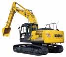
- 7 SERIES
US EPA Tier IV Final Complies with the latest exhaust emission regulations 0.75– 1.875 cu.yd. SAE 83,600 lb {37,900 kg} – 84,700 lbs {38,400 kg} 265 hp {198 kW} @ 1,900 rpm ( SAE NET ) Bucket Capacity : Engine Power : Operating Weight :
Hydraulic Excavator


1
PERFORMANCE BY DESIGN

The next generation of KOBELCO excavators bring together superior performance and thoughtful design like never before. Performance enhancements offer greater efficiency and productivity along with increased power and speed. Design improvements provide the ultimate in comfort and control.
KOBELCO refuses to compromise, creating machines that meet every challenge.
2
EXCEPTIONAL
PERFORMANCE JUST GOT EVEN BETTER
Higher Efficiency, Plus a Tier IV Final Compliant Engine
The new SK380SR is equipped with a Isuzu Tier IV Final compliant engine, which has a higher torque value. This engine is fitted with a diesel oxidation catalyst (DOC) and an SCR device to control emissions without using a diesel particulate filter (DPF).
Model: ISUZU 6HK1
Rated Power Output
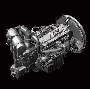
265 hp {198 kW} /1,900 rpm (SAE NET)
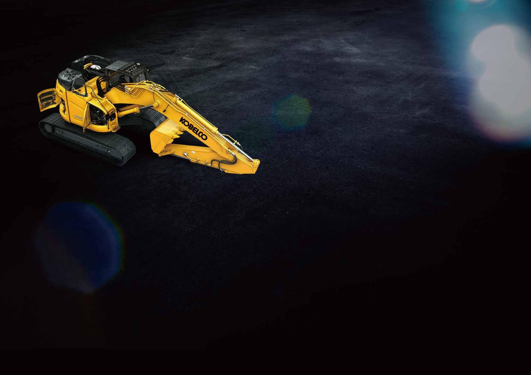
Short radius design occupies only one lane of highway
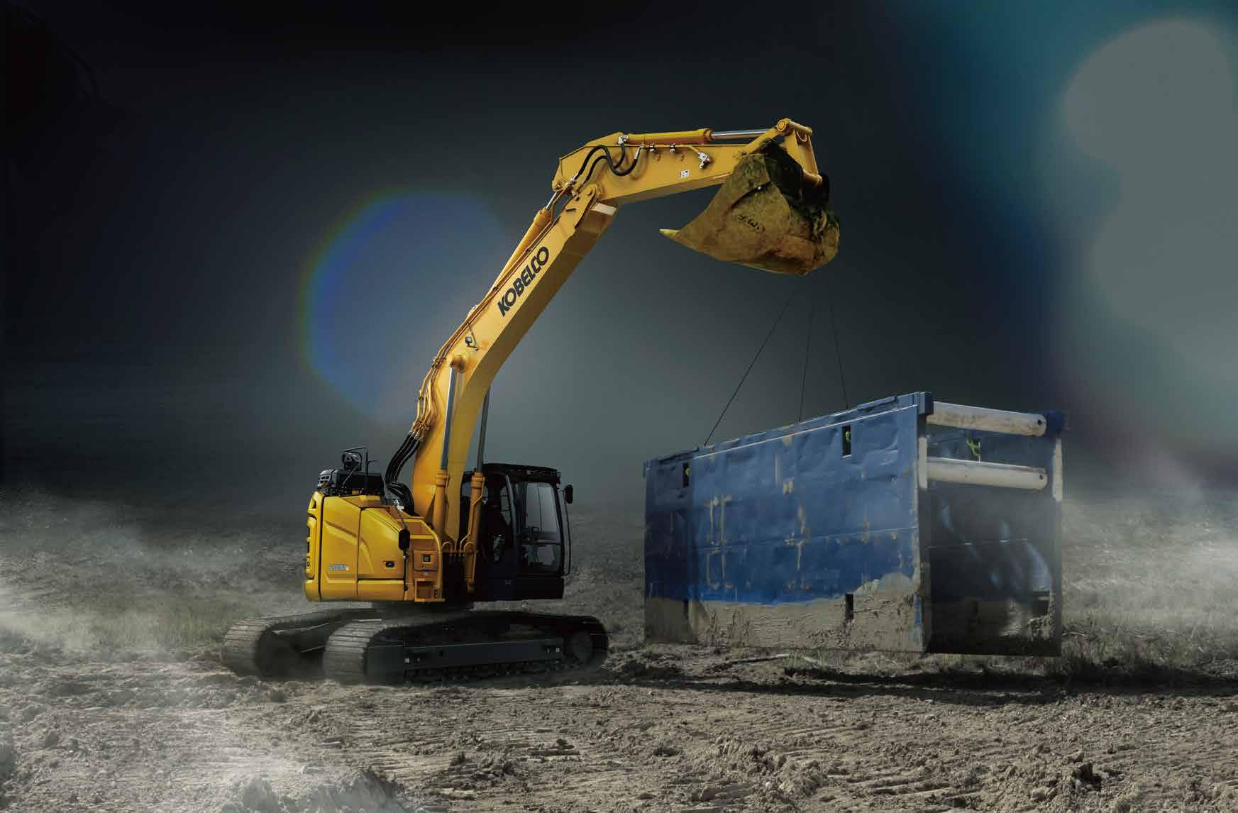
In addition to excellent lifting and digging performance, the SK380SR has adopted the attachment mode for a variety of tasks such as breaking and operates effectively even in narrow spaces as a single highway lane. Moreover, the cab permits operators to concentrate on work in a wide and comfortable space.

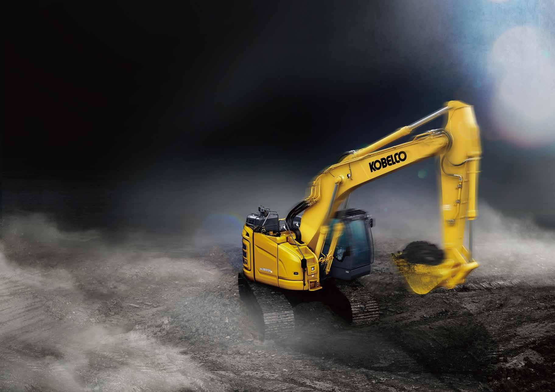
EXCELLENT LIFTING AND DIGGING PERFORMANCE IN NARROW SPACES
Drawbar Pulling Force (SAE J1309)
Excellent drawbar force lets you conquer rough terrain and slopes.
70,500 lbs {314 kN}
Lifting Capacity
27,540 lbs {12,490 kg}
(Ground level over front @20')
Heavy Lift
High hydraulic pressure (Heavy Lift) means greater lifting power, at close radius, allowing for smooth and steady operation while moving heavy objects.
Independent Travel
Automatic Independent Travel dedicates one hydraulic pump to travel and one to the attachment on a continuous basis, allowing for a smooth and constant movement speed even while swinging or using the boom or attachment. With Independent Travel, safely carrying a large pipe across a job site is a breeze.
Swing Priority
Our exclusive system automatically and instantly delivers full swing power during combined operations. There's no need to switch modes to make quick work of jobs like side-digging and back-filling.
5
Power Boost
When you need more power instantly, engage Power Boost to get 10% more power with no time limit.
Max. Bucket Digging Force (SAE)
With Power Boost:
41,100 lbs {183 kN}
Max. Arm Crowding Force (SAE)
With Power Boost: 30,100 lbs {134 kN}
6

7
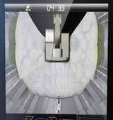
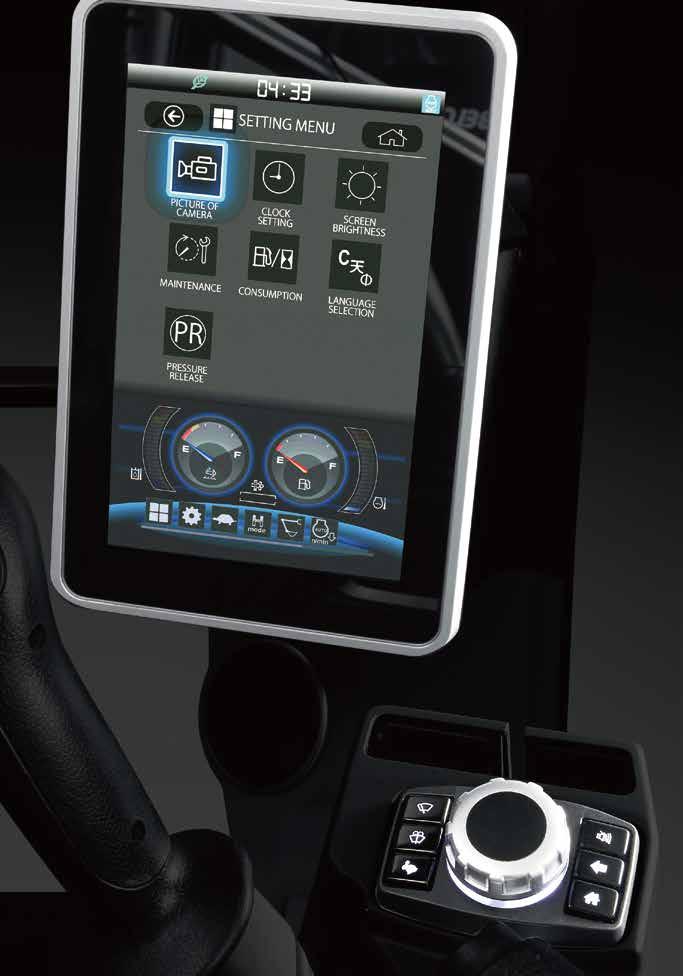
SAFETY ON FULL DISPLAY
Standard 3 Sides Safety Camera System
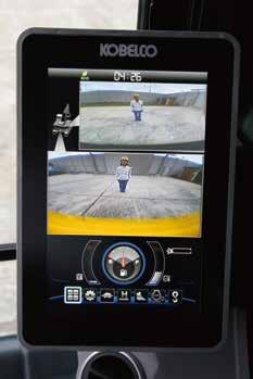
Our high-resolution, large display shows right, left and rear side cameras together. Multiple display allows the operator to customize viewing needs to enhance operator awareness and jobsite safety.


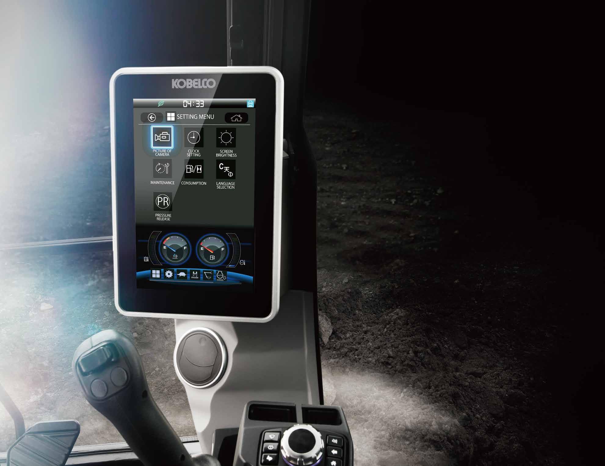
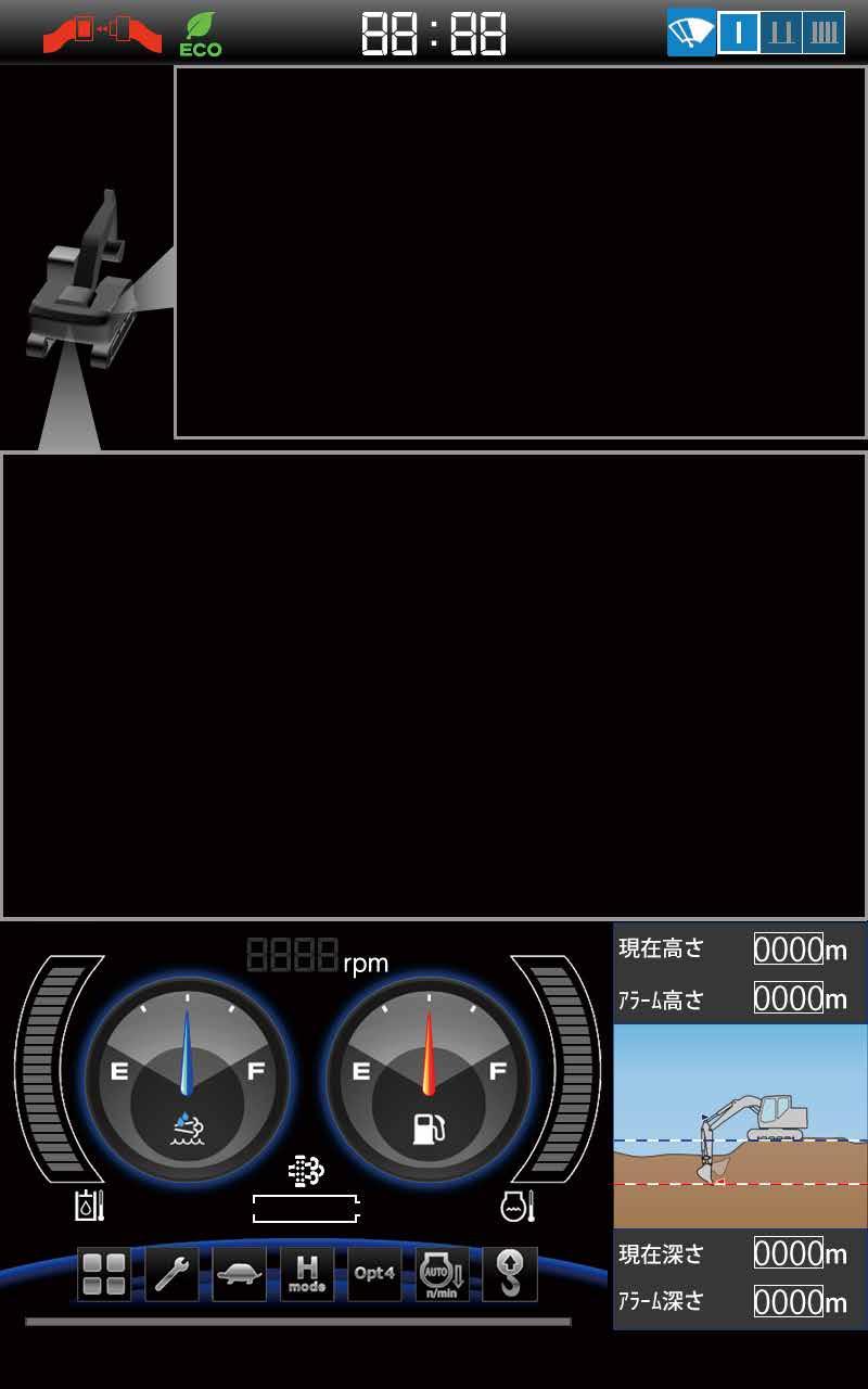
Large 10-Inch Color Monitor

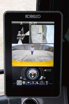

The easy -to -operate menu screen and recognizable icons assist the operator to select the most important information needed to ensure jobsite safety and machine control.
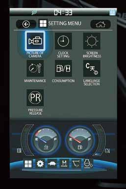
Dial in the Right Information
Simply turn the jog dial to the right or left to select an operational feature, then press the dial to confirm selection.

8
Rear view Rear view Right
Right
3
view
straight view
side view
sides
9
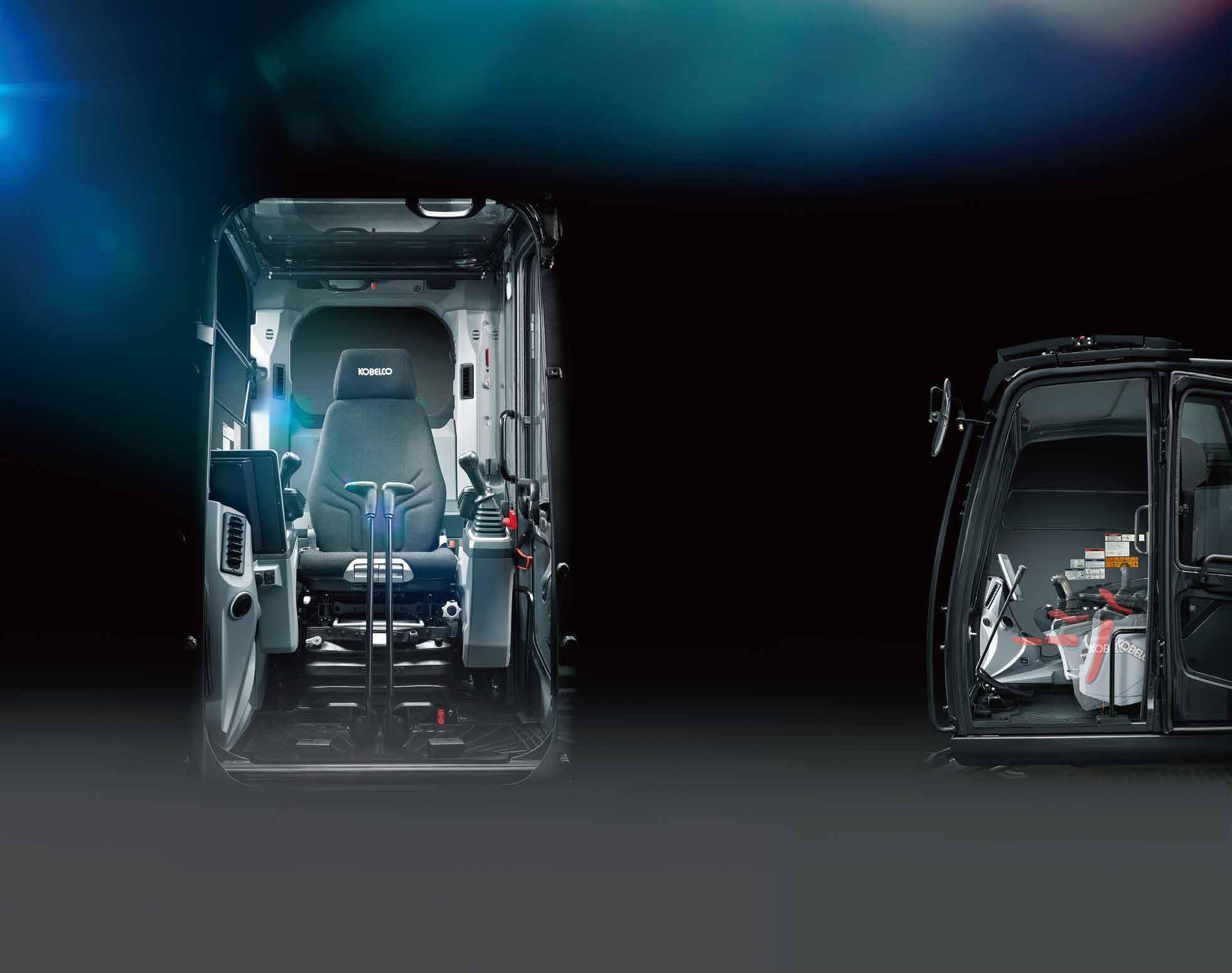
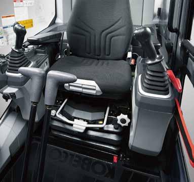
PREMIER OPERATOR COMFORTS
Heated Air Ride Suspension Seat
A 7-way adjustable seat achieves excellent shock absorption and superior ride comfort.
Multi Vent Air Conditioner
Cool air is blown from multiple outlets toward the operator’s body for more comfortable operation.
Ergonomic Lever Angles
Operators can move levers horizontally without twisting their wrists, reducing fatigue.
Adjustable Height Joysticks
Joystick height is manually adjustable to suit operator’s preference.
LED Interior Light
Interior lights turn on and off automatically when the door is open or the ignition is turned to the OFF position. This ensures safe entry and exit in the dark.
Tilting Left Side Console
Flip-up left console with integrated pilot control lock lever tilts for easy entry and exit from the cab.
10

THE ULTIMATE IN SIMPLE DESIGN
THE ULTIMATE IN SIMPLE DESIGN
In our pursuit of functional beauty and styling, we created an all new interior design focused with the operator in mind.
Jog Dial
This dial integrates multiple functions into a single, easy to use interface. Even with gloves on, the operator can make the adjustments they need.
LED Illumination
Dials and buttons are now backlit to provide a bright, clear view in any lighting condition.
11
12
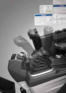
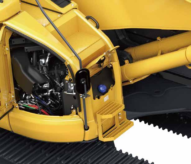
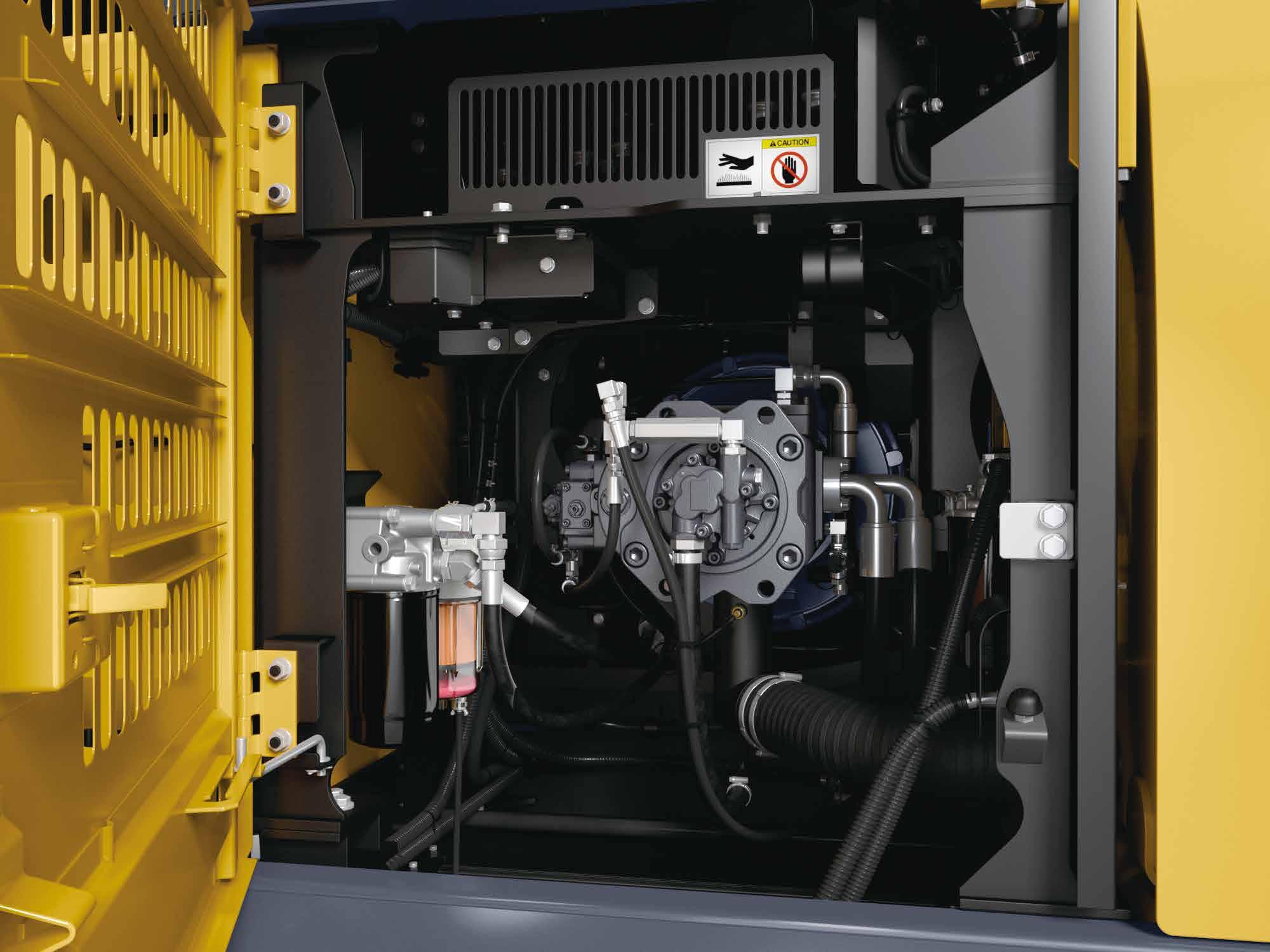
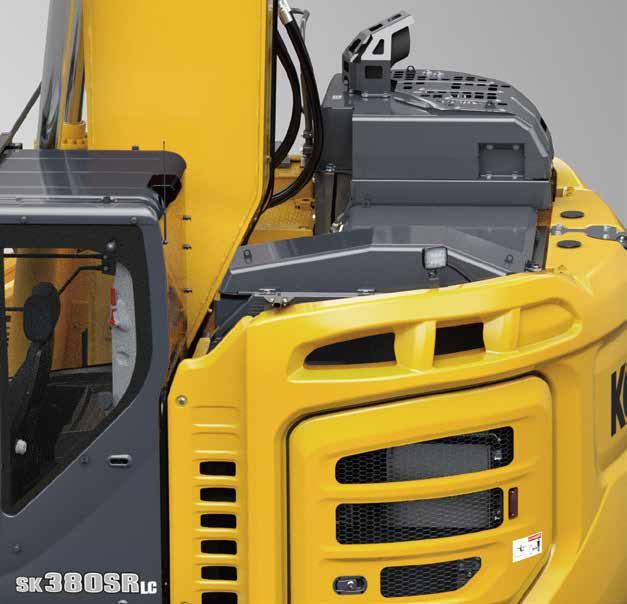
EASY MAINTENANCE
Top Guard Level II
The standard overhead cab guard can be tilted open with gas damper for easy window cleaning. Meets standard top guard level II requirements. ( ISO 10262 )
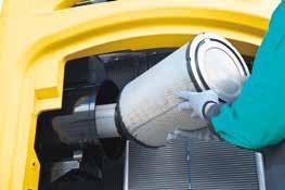
Two-Stage Air Filter Provides superior cleaning and engine protection.
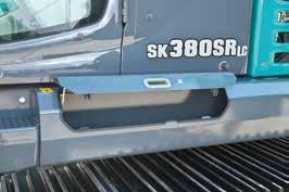
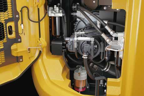
Ground level storage compartment access
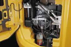
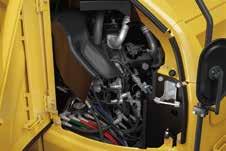
Right Side (Ground Level Maintenance) Hydraulic pump and engine filter compartment.
Ground level DEF tank
Control valve
Cleanly mounted with easy access to test ports.
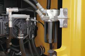
Filter / Pre-Filter with Integrated Water Separator.

13
Main
Travel Alarm
Specifications
Model ISUZU 6HK1
Direct injection, water-cooled,
Travel System
Drawbar pulling force Travel speed
Displacement
motor
Gradeability
Cab & Control
Hydraulic System
variable displacement pumps gear pump × 64.7 gpm { 2 × 245 L /min } 1 × 5.0 gpm { 1 × 19 L /min }
All-weather, sound-suppressed steel cab mounted on silicon-sealed viscous mounts and equipped with a heavy, insulated floor mat.
Two hand levers and two foot pedals for travel
Two hand levers for excavating and swing
Electric rotary - type engine throttle
Boom, Arm & Bucket Refilling Capacities & Lubrications
Swing System
Axial piston motor
Hydraulic; locking automatically when the swing control lever is in the neutral position
disk brake,
Hydraulic P.T.O.
cylinders
cylinder
Fuel tank
Cooling system
Engine oil
Travel reduction gear
Swing reduction gear
Hydraulic oil tank
DEF tank
Operating Weight & Ground Pressure
Specification
Auxiliary 4,970 {34.3} 3,263 {22.5} Max. flow U.S. gpm, { lpm } ( 0 pressure ) 1,900 Maximum pressure psi { MPa }
Rotation
Output 2 × 64.7 {2 × 245} 11.7 {44.3} rpm 31.5“ {800} 11'1“ {3,390} 83,600 {37,900} 7.7 {53} 31.5“ {800} 11‘1“ {3,390} 84,200 {38,200} 7.8 {54} 33.5“ {850} 11‘3“ {3,440} 84,700 {38,400} 7.4 {51} Shaped Single grouser shoes (even height) Triple grouser shoes (even height) shoe width overall width of crawler operation weight Ground pressure ft-in {mm} ft-in {mm} lb {kg} psi {kPa}
In standard trim, with standard boom, 10’2” {3.10 m} arm, and 1.57 cu.yd. {1.20 m3} ISO heaped bucket
Max. torque
power output
Rated
Bore and stroke No. of cylinders Type rpm ( Without fan ) rpm ( SAE NET ) 1,500 N·m } / 1,011 lb-ft { 745 1,500 N·m } / 1,080 lb-ft { 797 rpm ( Without fan ) rpm ( SAE NET ) 1,900 kW } / 198 hp { 265 1,900 kW } / 210 hp { 282 ml } cu.in 475.4 mm 125 mm × 115 } { 4.9 × 4.5 6
4-cycle diesel engine with turbocharger, intercooler, Tier IV Final certified
cooler
valve
pump
Travel
Boom, arm
bucket Max. discharge
Type Pump Relief valve setting Air cooled type 8- spool Gear type MPa } 34.3 psi { 4,970 MPa } 37.8 psi { 5,480 MPa } 34.3 psi { 4,970 MPa } 29.0 psi { 4,210 MPa } 5.0 psi { 725 2 + one Two Swing torque Swing speed Parking brake Brake Swing motor kN·m } 122.1 lb-ft { 90,100 rpm 8.4 Oil
hydraulic
Oil
Main control
Pilot control
Control circuit Swing circuit
circuit Power Boost
and
flow
operated automatically
Travel motors ° } 70% {35 kN } 314 lb { 70,500 km / h } 4.6/2.9 mph { 2.8/1.7 48 Oil disc
per
Hydraulic
2 x axial-piston, two-step motors mm } 1,361 ” { 6 ’ 4 mm } × 145 ” { 5.7 mm } 1,675 ” { 6 ’ 5 mm } × 150 ” { 5.9 mm } 1,208 ” { 0 ’ 4 mm } × 130 ” { 5.1 Bucket cylinder
Boom
Cab Control
Travel shoes Parking brakes Travel brakes
brake
brake per motor
Arm
L }: Tank oil level 2.0 L } 350 U.S.gal { 92.5 L } 41 U.S.gal { 10.9 L } 48.6 U.S.gal { 12.8 L } 7.4 U.S.gal { 2.0 245 U.S.gal { 64.7 L }: Hydraulic system 440 U.S.gal
116.2 L } 21
5.5 Engine
{
U.S.gal {
L } 7.5 U.S.gal {
2 × 2 × 15
” ” 7,790 {
each side
Working Ranges
Max. digging reach at ground level
Bucket capacity SAE heaped cu.yd. {m3}
Digging Force ( ISO 6015)
Dimensions
Ground clearance of rear end*
Ground clearance*
Tail swing radius
Distance from center of swing to rear end
Standard Arm Long Arm A G, G’ B H I E D L F C K J 1 2 3 4 5 6 7 8 9 10 11 12 13 m 12 m 11 10 9 8 7 6 5 4 3 2 1 0 1 2 3 4 5 6 7 8 a b h c e d j f g i SK380SRLC-7
Unit : ft - in { m} 20 m} 6.20 4 ” { ’ Boom Arm Range
j-
i-
hMax.
gMin.
fMax.
e-
d-
c-
bMax.
a-
Digging depth for 8’ {2.4 m} flat bottom
Horizontal digging stroke at ground level
Min. swing radius
vertical wall digging depth
dumping clearance
dumping clearance
Max. digging height
Max. digging depth
digging reach
Arm length
Overall height (to top of muffler guard) Overall width**
length G’ G F E D C B A Unit : ft - in { mm} L K J I H Overall width of upperstructure Shoe width Track gauge Overall length
Tumbler distance *Without including height of shoe lug. *Power Boost engaged. Unit : lb { kN} Arm length Arm crowding force Bucket digging force ISO SAE ISO SAE * 189 42,500 208 46,800 } { } { * 166 37,300 183 41,100 } { } { * 122 27,400 134 30,100 } { } { * 126 28,300 139 31,200 } { } { * 109 24,500 120 27,000 } { } { * 114 25,600 125 28,100 } { } {
Overall height (to top of boom) Overall
of crawler
} { ” ’10 35 } { ” 3 ’ 35 } { 11 22 } { ” 8 ’ 36 } { ” 9 ’ 26 } { ” 2 ’ 10 } { ” 1 ’ 20 } { ” 4 ’ 11 } { 4 18 } { ” 5 ’ 22 } 9,980 { ” 9 ’ 32 } 3,320 { ” ’11 10 {10,090} ” 1 ’ 33 } 3,710 { ” 2 ’ 12 } 3,440 { ” 3 ’ 11 } 3,580 { ” 9 ’ 11 } 1,160 { ” 10 ’ 3 } 485 { ” 19.1 } 1,900 { ” 3 ’ 6 } 1,900 { ” 3 ’ 6 } 4,050 { ” 3 ’ 13 } 4,960 { ” 3 ’ 16 } 2,590 { ” 6 ’ 8 } 3,180 { ” 5 ’ 10 } 850 { ” 33.5 1.57 } 1.20 { 1.57 } 1.20 { } { ” 9 ’ 37 } { ” 2 ’ 37 } { 9 24 } { ” 3 ’ 38 } { ” 3 ’ 28 } { ” 5 ’ 8 } { ” 5 ’ 22 } { ” 7 ’ 11 } { 9 20 } { ” 3 ’ 24 ” { **Shoe width: 33.5 850 mm} 16 m} Standard 3.10 { 2” ’ 10 m} Long 3.65 { 0” ’ 12 m} Standard 3.10 { 2” ’ 10 m} Long 3.65 { 0” ’ 12 m} Standard 3.10 { 2” ’ 10 m} Long 3.65 { 0” ’ 12 10.93 10.74 6.99 11.17 8.15 3.11 6.11 3.45 5.59 6.83 11.50 11.32 7.55 11.66 8.61 2.57 6.84 3.53 6.32 7.40
Lift Capacities
Rating over front
Rating over side or 360 degrees
{18,520} *40,830 {11,720} *25,840 {11,720} *25,840 {16,170} *35,650 {18,520} *40,830 {16,170} *35,650 {15,450} *34,080 {10,770} 23,760 {16,950} *37,390 {17,450} *38,480 {10,730} 23,660 {16,720} *36,870 {11,100} 24,480 {14,310} {11,040} *24,340 {11,040} *24,340 *31,570 {10,650} 23,500 {11,970} 26,400 {11,630} *25,660 {12,350} 27,240 {12,490} 27,540 {11,860} *26,150 {10,540} *23,250 {9,050} *19,960 {7,890} {7,440} *17,410 *16,420 {7,090} 15,640 {7,040} 15,540 {7,160} 15,800 {7,450} 16,440 {7,900} 17,420
A - Reach from swing centerline to arm top
B - Arm top height above/below ground
C - Lift point
Relief valve setting {Heavy Lift}: 5,480 psi {37.8 MPa}
{11,430} *25,210 {7,030} *15,500 {7,030} *15,500 {11,430} *25,210 {15,840} *34,930 {15,840} *34,930 {10,440} *23,030 {6,210} *13,710 {6,210} *13,710 {10,440} *23,030 {15,950} *35,170 {17,030} *37,550 {17,050} *37,590 {15,730} *34,690 {12,920} *28,490 {9,620} *21,210 {10,460} 23,070 {10,410} 22,960 {10,590} 23,360 {11,140} 24,580 {12,190} 26,880 {9,620} *21,210 {11,870} *26,180 {12,180} 26,860 {12,180} *26,870 {11,220} *24,750 {9,750} *21,500 {8,190} *18,070 {7,010} *15,470 {6,300} *13,900 {6,860} 15,130 {6,870} 15,160 {7,050} 15,550
Note:
1. Do not attempt to lift or hold any load that is greater than these lift capacities at their specified lift point radius and heights. Weight of all accessories must be deducted from the above lift capacities.
2. Lift capacities are based on machine standing on level, firm, and uniform ground. User must make allowance for job conditions such as soft or uneven ground, out of level conditions, side loads, sudden stopping of loads, hazardous conditions, experience of personnel, etc.
3. Bucket pin attachment point defined as lift point.
4. The above lift capacities are in compliance with ISO 10567. They do not exceed 87% of hydraulic lift capacity or 75% of tipping load. Lift capacities marked with an asterisk (*) are limited by hydraulic capacity rather than tipping load.
5. Operator should be fully acquainted with the Operator’s and Maintenance Instructions before operating this machine. Rules for safe operation of equipment should be adhered to at all times.
6. Lift capacities apply to only machine as originally manufactured and normally equipped by KOBELCO CONSTRUCTION MACHINERY CO., LTD.
17
{7,420} 16,360 {7,930} 17,490 {8,190} *18,070 {7,010} *15,470 {6,300} *13,900 {8,720} {8,710} {8,840} 19,500 {9,000} *19,860 {8,210} *18,110 {7,420} *16,360 {6,870} *15,150 {5,750} 19,230 19,210 *12,690 {5,060} {5,050} {5,170} 11,410 {5,390} 11,890 {5,660} 12,500 {5,940} 13,110 {6,150} 13,560 {5,750} 11,170 11,150 *12,690 {8.46m} 27’78“ {9.24m} 30’33“ {9.71m} 31’87“ {9.92m} 32’55“ {9.88m} 32’43“ {9.59m} 31’49“ {9.04m} 29’66“ {8.15m} 26’75“ {6.80m} 22’32“ Radius 5’0“{1.5m} 10’0“{3.0m} 15’0“{4.6m} 20’0“{6.1m} 25’0“{7.6m} At max. reach SK380SRLC Boom: 20’4” {6.20 m} Arm: 12’0” {3.65 m} Bucket: Without Counterweight: 19,600 lb {8,900 kg} Shoes: 33.5” {850 mm} {Heavy Lift} A B {-3.0m} -10’0“ {-1.5m} -5’0“ G.L. 5’0“ {3.0m} 10’0“ {4.6m} 15’0“ {6.1m} 20’0“ {7.6m} 25’0“ {9.1m} 30’0“ lb {kg} lb {kg} lb {kg} lb {kg} lb {kg} lb {kg} lb {kg} lb {kg} lb {kg} {19,090} *42,100 {19,090} *42,100 {13,640} *30,090 {10,710} 23,630 {10,130} *22,350 {7,030} 15,510 {7.28m} 23’89“ {-4.6m} -15’0“ lb {kg} {1.5m} {5,640} *12,440 {6,770} 14,940 {6,890} 15,210 {7,050} 15,550 {5,800} *12,800 {3,960} 8,740 {4,000} 8,820 {4,100} 9,060 {4,250} 9,370 {4,380} 9,660 {5,420} *11,970 {4,480} *9,880 {3,950} *8,710 {3,640} *8,030 {3,470} *7,660 {3,420} *7,550 {3,480} *7,680 {3,680} *8,130 {4,150} *9,170 {4,440} 9,800 {3,910} 8,630 {3,660} 8,090 {3,610} 7,980 {3,470} *7,660 {3,420} *7,550 {3,480} *7,680 {3,680} *8,130 {4,150} *9,170 {7,450} *16,440 {5,590} 12,340 30’0“{9.1m}
18,520
19,560
*19,350 {8,060} *17,770 {7,590} *16,750 {5,280} 11,660 {5,210} 11,500 {5,280} 11,660 {5,460} 12,040 {5,700} 12,570 {5,940} 13,110 {6,110} 13,490 {6,500} *14,350 {5,660} *12,500 {4,190} 9,250 {4,300} 9,490 {7,030} *15,500 {5,540} *12,230 {4,770} *10,530 {4,330} *9,550 {4,090} *9,020 {3,990} *8,810 {4,040} *8,910 {4,270} *9,430 {4,880} *10,770 {5,150} 11,370 {4,440} 9,800 {4,130} 9,110 {4,050} 8,950 {4,090} *9,020 {3,990} *8,810 {4,040} *8,910 {4,270} *9,430 {4,880} *10,770 25’55“ 28’31“ 29’96“ 30’69“ 30’56“ 29’56“ 27’60“ 24’43“ 19’44“ Radius 10’0“{3.0m} 15’0“{4.6m} 20’0“{6.1m} 25’0“{7.6m} 30’0“{9.1m} At max. reach SK380SRLC Boom: 20’4” {6.20 m} Arm: 10’2” {3.10 m} Bucket: Without Counterweight: 19,600 lb {8,900 kg} Shoes: 33.5” {850 mm} {Heavy Lift} A B {-3.0m} -10’0“ {-1.5m} -5’0“ G.L. 5’0“ {3.0m} 10’0“ {4.6m} 15’0“ {6.1m} 20’0“ {7.6m} 25’0“ {9.1m} 30’0“ lb {kg} lb {kg} lb {kg} lb {kg} lb {kg} lb {kg} lb {kg} lb {kg} lb {kg} {16,990} *37,460 {16,990} *37,460 {12,560} *27,700 {11,090} 24,460 {9,140} *20,170 {7,340} 16,200 {8,200} *18,090 {6,810} 15,020 21’24“ {-4.6m} -15’0“ lb {kg} {1.5m} {7.78m} {8.62m} {9.13m} {9.35m} {9.31m} {9.00m} {8.41m} {7.44m} {5.92m} {6.47m}
{8,400}
{7,890} {7,440} *17,410 *16,420 {8,720} *19,240 {8,870}
{8,950} 19,740 {9,140} 20,160 {8,770}
A B
C


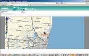
Total Support for Machines with Network Speed and Accuracy
KOMEXS is a telematics system for receiving machine information. Manage your machines anywhere in the world using the Internet.
Location, workload and diagnostic data aid business operations.


service personnel/dealer/customer

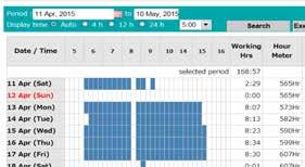
Direct Access to Operational Status
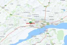
Location Data
Accurate location data can be obtained even from sites where communications are difficult.
Operating Hours
A comparison of operating times of machines at multiple locations shows which locations are busier and more profitable. Operating hours on site can be accurately recorded, for running time calculations needed for rental machines, etc.
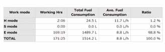
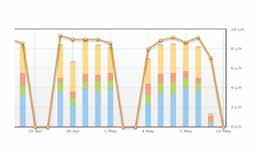
Fuel Consumption Data
Data on fuel consumption and idling times can be used to indicate improvements in fuel consumption.
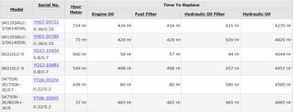
Maintenance Data and Warning Alerts
Machine Maintenance Data
Provides maintenance status of separate machines operating at multiple sites. Maintenance data is also relayed to KOBELCO service personnel, for more efficient planning of periodic servicing.
Graph of Work Content
The graph shows how working hours are divided among different operating categories, including digging, idling, traveling, and optional operations (N&B).
Warning Alerts
•This system warns an alert if an anomaly is sensed, preventing damage that could result in machine downtime.
Security System
Engine Start Alarm
Sends a notification if the engine is started outside of pre-defined hours.
Area Alarm
Sends a notification if the machine leaves a pre-defined area.
18
Base station Web server
KOBELCO
GPS
Hydraulic excavator
Daily report Fuel consumption Work status Digging Hrs Travelling Hrs Idle Hrs Opt Att Hrs Cane Mode Hrs Ave, Fuel Consumption
Latest location SK380SRLC-7
Standard and Optional Equipment
ISUZU 6HK1 (Tier IV Final certified)
Auto engine acceleration/deceleration
Auto Idle Stop
3 work modes H, S, Eco
Power boost
Heavy lift mode
Hydraulic Pressure Release
Independent travel
Swing priority
Boom to arm regeneration
Auto warm-up system
Bi-direction (proportional hand control) and single-direction auxiliary hydraulics (nibbler and breaker)
Rotation hydraulics with proportional hand control
Hydraulic oil VG46
Air suspension seat with heat
10-inch color monitor
LED door light
Automatic climate control
Radio (AM/FM, AUX, USB, Bluetooth® and hands-free telephone)
12V power outlet
7 LED work lights: 2 on boom, 2 on cab front, 2 on rear counterweight, 1 on front right
Standard boom 20’4” {6.20 m}
Standard HD arm 10’2” {3.10 m} with rock guard
Long arm 12’0” {3.65 m}
Standard C/W 19,600 lb {8,900 kg} with swing flashers
33.5” {850 mm} triple grouser shoe
31.5” {800 mm} triple grouser shoe
31.5” {800 mm} single grouser shoe
ROPS cab (ISO 12117-2:2008)
Tilt opening top cab guard (Top guard level II ISO 10262:1998)
Bar-type front guard (Front guard level II ISO 10262:1998)
Mesh-type front guard (Front guard level I ISO 10262:1998)
Engine emergency stop switch
3-inch retractable seat belt
Seatbelt indicator on display
Travel alarm
Swing flashers in counterweight
Left and right side mirrors
3-side 270-degree camera system
Hose burst valve for boom and arm cylinder
Angled upper deck guards
Machine Guidance ready brackets
Quick coupler piping ready brackets
ISO to BHL pattern changer
Battery disconnect switch
KOMEXS Machine Monitoring
4 Year or 4,000 Hour Warranty
Note: Bluetooth® is a registered trademark of the Bluetooth SIG Inc.
Note: This catalog may contain attachments and optional equipment that are not available in your area. And it may contain photographs of machines with specifications that differ from those of machines sold in your areas. Please consult your nearest KOBELCO distributor for those items you require. Due to our policy of continuous product improvements all designs and specifications are subject to change without advance notice.
Copyright by No part of this catalog may be reproduced in any manner without notice.
22350 Merchants Way, Katy, TX 7 7449
Tel: 281-888-8430 Fax: 281-506-8713
www.KOBELCO-USA.com
Single pedal travel is the corporate mark used by Kobe Steel on a variety of products and in the names of a number of Kobe Steel Group companies.
Inquiries To:
Bulletin SK380SRLC-7 -NA-201-2304XXEX
=Std =Opt Category Description SK380SRLC-7 Engine Hydraulic system Cabin Lights Working equipment Counter weight Undercarriage Safety
Others
