Knauf Metal Furring (MF) Suspended Ceiling Membranes
Appendix
The 100% Knauf System Performance Warranty
Amendment table
For further information on these amendments, please contact our Technical Services via email; technical-uk@knauf.com or call 0800 521050 (option 2).
001 New publication launch: Knauf EN System Performance Tables (September 2023).
002 Document Title: Knauf EN System Performance Tables. 1. Removal of system: P-C-92-1x15-SSP-50. New system added as replacement: P-C-92-1x15-SSP-25 (page 8).
003 Document Title: Knauf EN System Performance Tables. 1. Change of sound insulation performance of P-CRB1-70-2x15-SSP-50. Acoustic change from 53 to 55dB Rw +Ctr (dB) and 59 to 60dB (Rw) (page 11).
004 Document Title: Knauf EN System Performance Tables. 1. Adjustment in height (mm) for systems P-C-1x15-SSP-25 | P-C-92-2x15-SSP-25 | P-C-146-1x15-SSP-25 | P-C-146-2x15-SSP-25. 5000mm to 4000mm (page 8).
005 Document Title: Knauf EN System Performance Tables. 1. Adjustment in height (mm) for systems P-C-70-1x15-FP-0 | P-C-92-1x15-FP-0. 4000mm to 3000mm (page 7). 08.02.24
006 1. Development of new layout of document - Knauf EN System Performance Tables September 2023 to Knauf EN Compliance Systems (April 2024). New layout and new updated system codes implemented. All document.
008 1. Admendment table added (page 3). 2. Updated Table Header Definitions (page 6). 3. Additional Knauf Isolator System - Double 50 'C' (0.55) Stud (page 15) . 4. New system category added: Framed Encasement System - Fire Panel (pages 22-25). 5. Additional MF Suspsended Ceiling Membranes - 12.5mm 15mm Solutions using Wallboard, Moisture Panel, Soundshield Plus (page 26). New tone added throughtout document.
009 Added: 1. New System Category: Knauf Horizontal Shaftwall – Ceiling System (Page 19). 2. Performer System: 12.5mm Knauf Wallboard with Knauf Insulation 25mm Acoustic Roll solutions, 50 ‘C’, 70 ‘C’, 92 ‘C’, 146 ‘C’ fire performance change from 'NA' to '30' (page 8). 3. 2 x 15mm Knauf Performance Plus with Knauf Insulation 25mm Acoustic Roll solutions, 70 ‘C’, 92 ‘C’, 146 ‘C’ acoustic sound insulation change from '52' to '54'. 4. 1 x 15mm Knauf Soundshield Plus with Knauf Insulation 25mm Acoustic Roll solutions, 70 ‘C’, 92 ‘C’, 146 ‘C’ acoustic sound insulation change from '45' to '47' (page 11). 5. 2 x 15mm Knauf Soundshield Plus with Knauf Insulation 25mm Acoustic Roll solutions, 70 ‘C’, 92 ‘C’, 146 ‘C’ acoustic sound insulation change from '52' to '55' (page 11). 6. Knauf Isolator Systems – new format designated as unbraced and braced solutions with system code updates and braced acoustic note (Pages 15 | 16). 7. Added – New 100% Knauf System Performance Warranty Page (Page 30). 8. Note: Contents page reflected. Added - Month and revision to front cover (page 1).
010 1. Document name change - Knauf EN Compliance Systems to Knauf System Performance Tables (EN compliance) (front cover). 2. New updated links to documentation (page 4). 3. Knauf Performer - Wallboard. System constructions: 2 x 12.5mm Knauf Wallboard, 50'C',70'C',92'C',146'C', Knauf Insulation 25mm Acoustic Roll, fire performance change from 'NA' to '60' and system maximum height changes for 70'C',92'C',146'C' (page 8). 4. Knauf Performer - Wallboard. System construction 2 x 15mm Knauf Wallboard, 50 'C' Stud solution, acoustic insulation change from '44' to '45' (page 8). 5. Knauf Performer - Wallboard. System constructions: 2 x 15mm Knauf Wallboard,70'C',92'C',146'C', Knauf Insulation 25mm Acoustic Roll, fire performance change from '30' to '60' (page 8). 6. Knauf Performer - Moisture Panel. System construction 2 x 15mm Knauf Moisture Panel, 50 'C' Stud solution, acoustic insulation change from '44' to '45' (page 9). 7. Knauf Performer - Fire Panel. System construction 2 x 15mm Knauf Fire Panel, 50 'C' Stud solution, acoustic insulation change from '44' to '45' (page 10). 8. Knauf Performer - Fire Panel. System constructions: 1 x 12.5mm Knauf Fire Panel, 50'C',70'C',92'C',146'C', Knauf Insulation 25mm Acoustic Roll, fire performance change from 'NA' to '30' and system maximum height changes for 92'C',146'C' (page 10). 9. Knauf Performer - Fire Panel. System constructions: 2 x 12.5mm Knauf Fire Panel, 70'C', 92'C',146'C' reduced heights (page 10). 10. Knauf Performer - Soundshield Plus. System constructions: 1 x 12.5mm Knauf Soundshield Plus, 50'C',70'C',92'C',146'C', Knauf Insulation 25mm Acoustic Roll, fire performance change from 'NA' to '30' and system maximum height changes for 92'C',146'C' (page 11). 11. Knauf Performer - Soundshield Plus. System construction: 1 x 15mm Knauf Soundshield Plus, 50'C', Knauf Insulation 25mm Acoustic Roll, fire performance change from 'NA' to '60' (page 11). 12. Knauf Performer - Soundshield Plus. System constructions: 1 x 15mm Knauf Soundshield Plus, 50 'C' Stud, clear cavity acoustic performance change from '38' to '37'. 1 x 15mm Knauf Soundshield Plus, 50 'C' Stud, 25mm Acoustic Roll acoustic performance change from '45' to '42'. 2 x 15mm Knauf Soundshield Plus, 50 'C' Stud, 25mm Acoustic Roll acoustic performance change from '51' to '52'. (page 11). 13. Knauf Performer - Soundshield Plus. System constructions: 2 x 12.5mm Knauf Soundshield Plus, 50'C',70'C',92'C',146'C', Knauf Insulation 25mm Acoustic Roll, fire performance change from 'NA' to '60' and system maximum height changes for 92'C',146'C' (page 11). 14. Knauf Performer - Soundshield Plus. System constructions: 2 x 15mm Knauf Soundshield Plus, 50'C',70'C',92'C',146'C', Knauf Insulation 25mm Acoustic Roll fire performance change from 'NA' to '120' and system maximum height changes for 92'C',146'C' (page 11). 15. Knauf Performer - Performance Plus. System constructions: 1 x 15mm Knauf Performance Plus, 50 'C' Stud, clear cavity acoustic performance change from '38' to '37'. 1 x 15mm Knauf Performance Plus, 50 'C' Stud, 25mm Acoustic Roll acoustic performance change from '45' to '42'. 2 x 15mm Knauf Performance Plus, 50 'C' Stud, 25mm Acoustic Roll acoustic performance change from '51' to '52'. (page 12). 16. Knauf Performer - Performance Plus. System constructions: 1 x 12.5mm Knauf Performance Plus, 50'C',70'C',92'C',146'C', Knauf Insulation 25mm Acoustic Roll fire performance change from 'NA' to '30' and system maximum height changes for 92'C',146'C' (page 12). 17. Knauf Hybrid Performer Systems removed and superseded with Knauf Performer offerings (page 13 of 010 Revision). 18. Knauf Framed Encasement - Fire Panel, updated to reflect ASFP Yellow Book 6th Edition (pages 23-26).
011 1. Introduction of new Knauf Frameless Encasement System - Fireboard (page 27). 2. Knauf Performer - Wallboard. System Construction: 2 x 15mm Knauf Wallboard, 146'C', Knauf Insulation 25mm Acoustic Roll acoustic performance change from '53' to '54' (page 8). 3. Knauf Performer - Moisture Panel. System Construction: 2 x 15mm Knauf Moisture Panel, 146'C', Knauf Insulation 25mm Acoustic Roll acoustic performance change from '53' to '54' (page 9). 4. Knauf Performer - Fire Panel. System Construction: 2 x 15mm Knauf Fire Panel, 146'C', Knauf Insulation 25mm Acoustic Roll acoustic performance change from '53' to '54' (page 10).
5. New Knauf Isolator (Twin Frame) Partitions - Braced EN-ICB-70-055-6-2x15-SSP-2x25 (214/120). 6. BS EN 1366-8: 2004 to BS EN 1366-8: 2024 (page 18).
10.02.25 MB
16.05.25 MB
System Finder - Request For EN or BS compliance systems
Testing
Methodology: BS EN 1363-1 AND BS 476-20
• Knauf interior drywall partition systems* that achieve a fire resistance performance are tested in accordance with BS EN 1363-1 and BS EN 1364-1. These are the up to date and most rigorous test methodology standards to follow.
• Determining the maximum height of a drywall partition as per the BS EN 1363-1 fire test methodology, is typically restricted by the 3 metre height of the test furnace.
• To understand the true maximum height of the system whilst under fire test conditions (‘Fire State Height’), there are three options. Increases can be determined by utilising greater test furnace heights, via Extended Field of Application (as outlined in BS EN 15254-3 - it is important to note this standard applies to single metal frame symmetrical systems only), or via BS EN 1364-1.
• The BS 476-20 standard is also restricted by the 3 metre height of the test furnace. However, under this BS standard, increasing the maximum heights of a system can be based on the ‘Cold State Height’. The cold state height is calculated using structural engineering methods to L/240 @ 200Pascals. (L = Height of wall).
Regulatory Requirements
• Specific to Approved Document B (England) there is a requirement to use European classifications and fire resistance test methodologies in accordance with BS EN 1363-1 and BS EN 1364-1, which means that the fire state height must be considered. However, Approved Document B (England) currently allows the usage of the BS 476 series, though it should be noted that, following consultation, the full BS 476 series will be removed in 2029. For other nationals, please consult relevant approved documents, technical guidance, and handbooks.
Knauf Approach & Recommendations
• Knauf advise and promote that EN compliance should be followed. That is to say Knauf advise utilising an EN 1364-1 fire resistance test and extend the maximum height of a drywall partition system via either BS EN 15254-3, BS EN 1364-1 or via a fire resistance test within a test rig greater than 3m in height.
• Projects that wish to use the BS 476 series must gain agreement between the Client, Accountable Persons, Duty Holders, and Local Building Control that the cold state height is an acceptable methodology.
For further information on Knauf system types that are applicable to support projects focusing on BS compliance, rrefer to Knauf Systems Performance Tables (BS compliance), available at Download Center or contact Knauf Technical Services – technical-uk@knauf.com or via telephone 0800 521050 (option 2).
*Performer (Partitions), Performer (Partitions with Resilient Bar), Isolator (Twin Frame), Shaftwall, Smokeshaft and Independent ‘I’ Stud Lining.
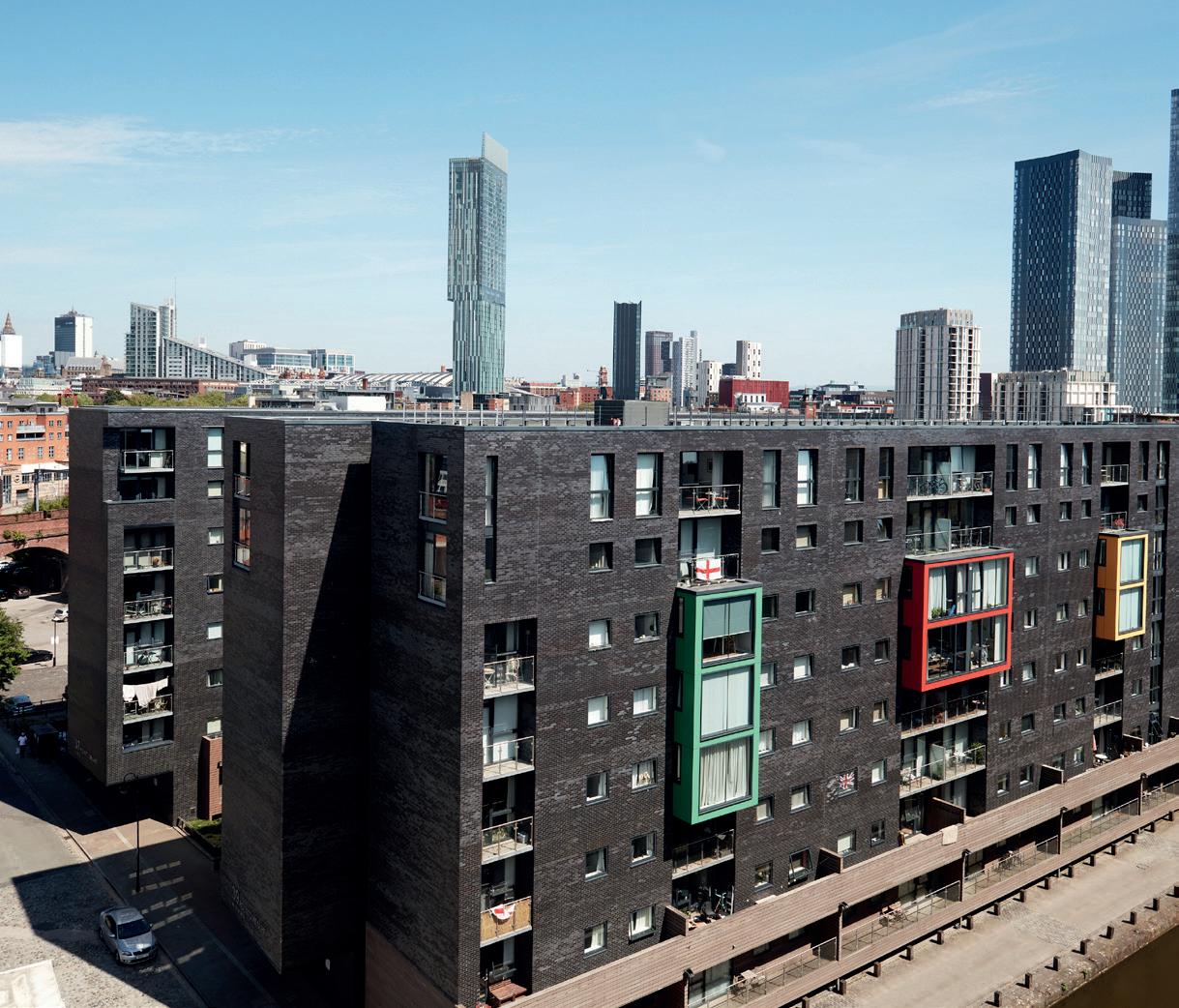
When choosing your Knauf systems please also refer to Knauf Fire Rated Deflection Heads document
An introduction to Knauf Drywall Systems
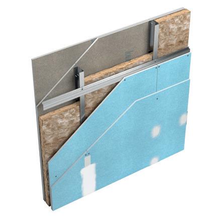
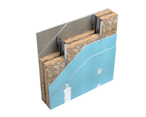
Knauf Performer Partition
The Knauf Performer system is our most versatile and commonly used partition system. It is constructed using a single row of Knauf metal studs with Knauf plasterboards to both sides in order to meet fire, acoustic, moisture and impact requirements. The Performer system is lightweight, simple to construct and should be used in conjunction with Knauf’s finishing solutions range.
Knauf Performer Partition with Knauf Resilient Bar
Knauf Resilient Bar can be added to both or one side of certain Knauf Performer systems. This additional component improves the acoustic sound reduction performance of the system in order to meet higher acoustic requirements.
The Knauf Isolator system is typically used to divide habitable dwellings. The twin stud build up, combined with Knauf’s high performance plasterboards, maximises acoustic performance in order to comply with building regulations, technical handbooks and guidances for sound insulation.
Knauf Shaftwall
Knauf Shaftwall is our innovative system to form enclosures around service and lift shafts while working from one side. The unique Knauf ‘C-T’ Stud makes this possible with a minimum of components. The system can provide a high level of fire resistance performance to meet the requirements of your project.
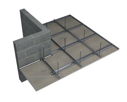
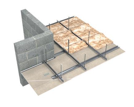
Knauf Horizontal Shaftwall - Ceiling System
Knauf Horizontal Shaftwall - Ceiling System is our innovative, non-loadbearing independent ceiling system (membrane) providing fire resistance from below and or from above. The unique arrangement allows the system to be built from one side.
Knauf Smokeshaft
Knauf Smokeshaft is a system to be used when an A1 fire classification board (in accordance with BS EN 13501-1) is required to line a shaft.
Knauf ‘I’ Stud Linings
Knauf Independent ‘I’ Stud is a fully independent wall lining system that can be used in all building types to upgrade the acoustic, fire and thermal performance of an existing masonry wall and to deal with any irregularities. Due do the system using an Knauf ‘I’ Stud, there is no requirement for the lining system to be fixed back into the structure behind.
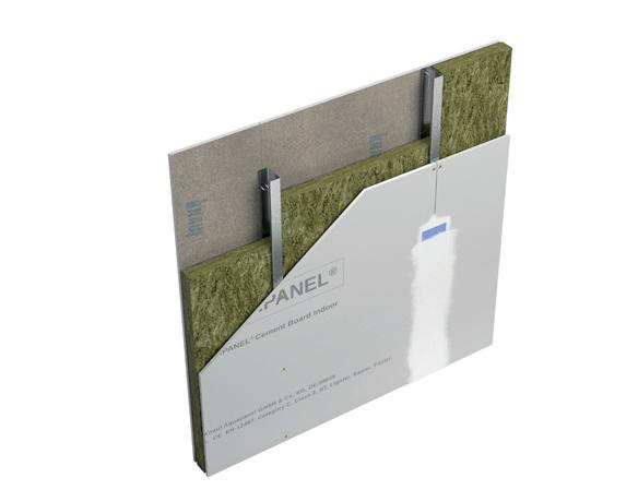
Knauf AQUAPANEL® Cement Board Indoor Board / Interior System
Knauf AQUAPANEL® Cement Board Indoor is exceptionally tough and durable, providing a solid tile backing substrate for wet indoor areas such as swimming pools, leisure centres, bathrooms and kitchens. The board is used in conjunction with specialist screws and finishing products to provide a full Knauf solution for humid and wet conditions.
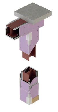
Knauf Framed Encasement System – Fire Panel
Knauf Framed Encasement System is a specialist fire protection encasement system designed to protect loadbearing universal beams and or columns. The use of Knauf Fire Panel plasterboard and specialist encasement Knauf components provide a simple and easy to install system.
Knauf Frameless Encasement System – Fireboard
Knauf Frameless Encasement System is another specialist fire protection encasement system designed to protect loadbearing universal beams and or columns. The use of Knauf Fireboard can be fixed together using staples without any Knauf metal components.
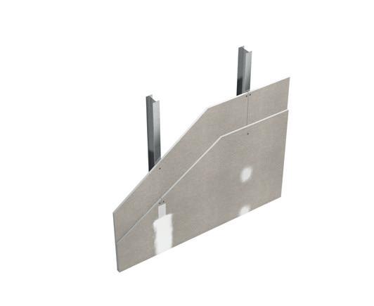
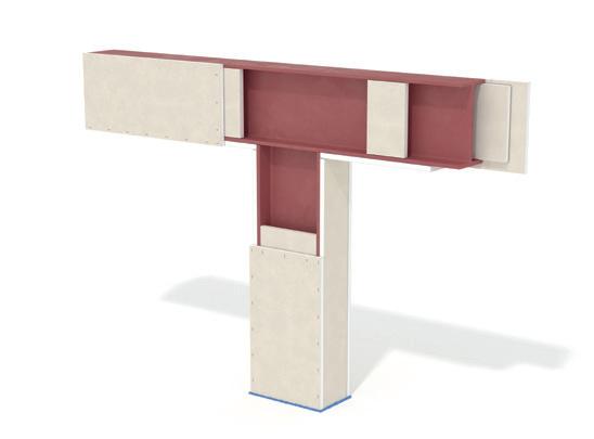
Knauf Metal Furring (MF) Suspended Ceiling System
The Knauf Metal Furring (MF) Suspended Ceiling system is versatile and easy to install. Deep voids are easily created to hide services and the ceiling can be used to provide fire protection to the soffit above. The Knauf MF Suspended Ceiling system is very familiar to contractors who will easily be able to form openings, bulkheads and coffers.
Table Header Definitions
The number of layers Knauf plasterboard fixed to either side of Knauf metal stud frame Knauf plasterboard/ board type
System width (in mm) which excludes finishes
The system code is a unique code that allows for easy reference if enquiring about a system.
EN-PC-50-055-6-1-12.5-WB-0
EN This is the standard in which this is accepted
PC System name (Performer) and stud type (C)
50 Stud Depth 50 (mm)
055 Stud Gauge 0.55 (mm)
6 Stud centres, 6= 600, 4= 400 and 3=300 (mm)
1 Layers of plasterboard on either side
15 Thickness of each individual board
WB Plasterboard type (Wallboard)
0 Thickness in mm of insulation in cavity
Acoustic Sound Insulation of system in measured in dB(Rw). Refer to appendix for test methodology.
Knauf metal component information providing size and gauge
Thickness of Knauf plasterboard/ board
Thickness of insulation used within Knauf metal stud frame. Refer to tables for information of Knauf Insulation type.
Partition Height
Fire resistance period of system in minutes. Refer to appendix for test methodology
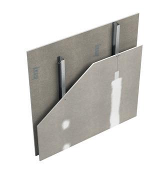
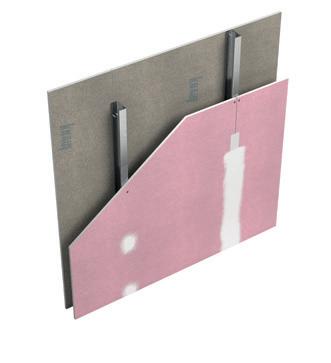
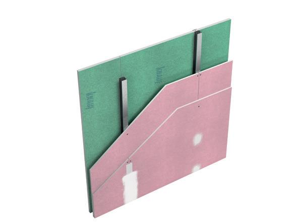
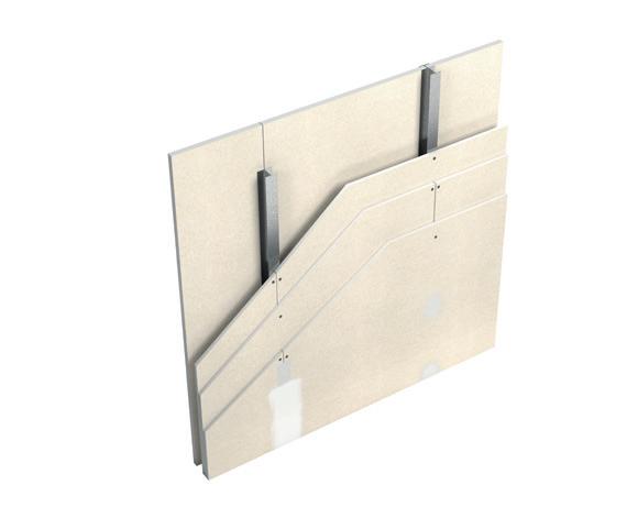
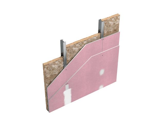
Knauf Perfomer Partitions – Isometrics
–
‘C’ Stud Partition – Soundshield Plus
Stud Partition –
Performer ‘C’ Stud Partition – Performance Plus
Stud Partition – Fire Panel
Click on typical system image to view performance details.
Refer to appendix for further information on performance of Performer partitions.
Knauf Performer ‘C’ Stud Partition
Wallboard
Knauf Performer ‘C’
Moisture Panel
Knauf Performer ‘C’
Knauf Performer
Knauf
Knauf Performer ‘C’ Stud Partitions – Wallboard
Performance tables
For further information on Knauf system performances, details and guidance on installation, please contact our Technical Services via email; technical-uk@knauf.com or call 0800 521050 (option 2).
1
2
2
2
*Knauf Insulation Acoustic Roll
For superscripts; 1,2 and 3, please refer to the appendix on page 32 for further information.
Note: Systems designed to accommodate up to -25mm or +/-12.5mm deflection allowance. Please refer to Knauf Fire Rated Deflection Head document for detailed information on design and specification.
For further information on Knauf system performances, details and guidance on installation, please contact our Technical Services via email; technical-uk@knauf.com or call 0800 521050 (option 2).
2
2
1 12.5 Moisture Panel 0 97
1 15 Moisture Panel 25 102
2 12.5 Moisture Panel 0 122
2 12.5 Moisture Panel 25 122
2 15 Moisture Panel 0 132
2 15 Moisture Panel
1
1
1
2
2
*Knauf Insulation Acoustic Roll
For superscripts; 1,2 and 3, please refer to the appendix on page 32 for further information. Note: Systems designed to accommodate up to -25mm or +/-12.5mm deflection allowance. Please refer to Knauf Fire Rated Deflection Head document for detailed information on design and specification.
Knauf Performer ‘C’ Stud Partitions – Fire Panel
Performance tables
For further information on Knauf system performances, details and guidance on installation, please contact our Technical Services via email; technical-uk@knauf.com or call 0800 521050 (option 2).
2
2
2
2
2
2
1
2 12.5 Fire Panel 0 122
2
2
*Knauf Insulation Acoustic Roll
For superscripts; 1,2 and 3, please refer to the appendix on page 32 for further information. Note: Systems designed to accommodate up to -25mm or +/-12.5mm deflection allowance. Please refer to Knauf Fire Rated Deflection Head document for detailed information on
Knauf Performer ‘C’ Stud Partitions – Soundshield Plus
Performance tables
For further information on Knauf system performances, details and guidance on installation, please contact our Technical Services via email; technical-uk@knauf.com or call 0800 521050 (option 2).
2
2
2
1
1
1
2
1
2
2
2
2
2
*Knauf Insulation Acoustic Roll
For superscripts; 1,2 and 3, please refer to the appendix on page 32 for further information.
Note: Systems designed to accommodate up to -25mm or +/-12.5mm deflection allowance. Please refer to Knauf Fire Rated Deflection Head document for detailed information on design and specification.
Knauf Performer ‘C’ Stud Partitions – Performance Plus
Performance tables
For further information on Knauf system performances, details and guidance on installation, please contact our Technical Services via email; technical-uk@knauf.com or call 0800 521050 (option 2).
1
1
2
2
2
2
2
2
1
2
2
*Knauf Insulation Acoustic Roll
For superscripts; 1,2 and 3, please refer to the appendix on page 32 for further information.
Note: Systems designed to accommodate up to -25mm or +/-12.5mm deflection allowance. Please refer to Knauf Fire Rated Deflection Head document for detailed information on design and specification.
Knauf Performer Partition with Knauf Resilient Bar
Performance tables
For further information on Knauf system performances, details and guidance on installation, please contact our Technical Services via email; technical-uk@knauf.com or call 0800 521050 (option 2).
*Knauf Insulation Acoustic Roll
Superscripts:
1. The maximum height stated is the lower value between the cold state height, calculated structurally to limiting deflection of L/240 @ 200Pa and the fire state height, as outlined in accordance with BS EN 1364-1.
2. Fire resistance period
Tested in accordance with BS EN 1364-1.
Fire resistance period is inclusive of both fire integrity and fire insulation. Fire resistance performance must be reviewed against Knauf specifications, standard details, with inclusion of deflection head arrangement.
3. Acoustic sound insulation
Tested or assessed in accordance with BS EN ISO 10140-1 & BS EN ISO 10140-2.
Acoustic sound insulation performance based on studs at 600mm centres only and non-deflection head arrangement.
Note 1. System that require fire resistance and/or acoustic sound insulation performance must have all outer joints taped and filled in accordance with Knauf recommendations. Systems are tested as imperforate.
Note 2. Systems designed to accommodate up to -25mm or +/-12.5mm deflection allowance. Please refer to Knauf Fire Rated Deflection Head document for detailed information on design and specification.
Isometric of Knauf Performer with Knauf Resilient Bar
Knauf Isolator (Twin Frame) Partitions - Unbraced
Performance tables
For further information on Knauf system performances, details and guidance on installation, please contact our Technical Services via email; technical-uk@knauf.com or call 0800 521050 (option 2).
Knauf
System Code & Maximum height1 (mm) @
EN-IC-70-055-6-2x15-SSP-2x25(229/60) 3000
System Code & Maximum height1 (mm) @ 400mm centres
EN-IC-70-055-4-2x15-SSP-2x25(229/60) 3000
System Code & Maximum height1 (mm) @ 300mm centres
EN-IC-70-055-3-2x15-SSP-2x25(229/60) 3000
Code & Maximum height1 (mm) @ 600mm centres
EN-IC-70-055-6-2x15-SSP-2x25(229/90) 3000
System Code & Maximum height1 (mm) @ 400mm centres
EN-IC-70-055-4-2x15-SSP-2x25(229/90) 3000
System Code & Maximum height1 (mm) @ 300mm centres
EN-IC-70-055-3-2x15-SSP-2x25(229/90) 3000
System Code & Maximum height1 (mm) @ 600mm
EN-IC-70-055-6-2x15-SSP-2x25(229/120) 3000
System Code & Maximum height1 (mm) @ 400mm centres
EN-IC-70-055-4-2x15-SSP-2x25(229/120) 3000
System Code & Maximum height1 (mm) @ 300mm centres
EN-IC-70-055-3-2x15-SSP-2x25(229/120) 3000
*Knauf Insulation Acoustic Roll
** Bracing using Knauf Flat Plate at 1500mm centres
† System fire resistance tested with the inclusion of baffle boxes
For superscripts; 1,2 and 3, please refer to the appendix on page 32 for further information. Note: Systems designed to accommodate up to -25mm or +/-12.5mm deflection allowance. Please refer to Knauf Fire Rated Deflection Head document for detailed information on design and specification.
Knauf Isolator (Twin Frame) Partitions - Braced
Performance tables
For further information on Knauf system performances, details and guidance on installation, please contact our Technical Services via email; technical-uk@knauf.com or call 0800 521050 (option 2).
System Code & Maximum height1 (mm) @ 600mm centres
EN-ICB-50-055-6-2x15-SSP-2x25(170/90) 4000
System Code & Maximum height1 (mm) @ 400mm centres
EN-ICB-50-055-4-2x15-SSP-2x25(170/90) 4000
System Code & Maximum height1 (mm) @ 300mm centres
EN-ICB-50-055-3-2x15-SSP-2x25(170/90) 4000
EN-ICB-70-055-6-2x15-SSP-2x25(214/120) 6000
System Code & Maximum height1 (mm) @ 400mm centres
EN-ICB-70-055-4-2x15-SSP-2x25(214/120) 6000
System Code & Maximum height1 (mm) @ 300mm centres
EN-ICB-70-055-3-2x15-SSP-2x25(214/120) 6000
*Knauf Insulation Acoustic Roll
** Bracing using Knauf Flat Plate at 1500mm centres
For superscripts; 1,2 and 3, please refer to the appendix on page 32 for further information. Note: Systems designed to accommodate up to -25mm or +/-12.5mm deflection allowance. Please refer to Knauf Fire Rated Deflection Head document for detailed information on design and specification.
For further information on Knauf system performances, details and guidance on installation, please contact our Technical Services via email; technical-uk@knauf.com or call 0800 521050 (option 2).
*Knauf Insulation Acoustic Roll
** Bracing using Knauf Flat Plate at 1500mm centres
EN-IC-70-055-6-2x15-SSP-2x15-PP-2x25(229/60) 3000
System Code & Maximum height1 (mm) @ 400mm centres
EN-IC-70-055-4-2x15-SSP-2x15-PP-2x25(229/60) 3000
System Code & Maximum height1 (mm) @ 300mm centres
EN-IC-70-055-3-2x15-SSP-2x15-PP-2x25(229/60) 3000
EN-IC-70-055-6-2x15-SSP-2x15-PP-2x25(229/90) 3000
System Code & Maximum height1 (mm) @ 400mm centres
EN-IC-70-055-4-2x15-SSP-2x15-PP-2x25(229/90) 3000
System Code & Maximum height1 (mm) @ 300mm centres
EN-IC-70-055-3-2x15-SSP-2x15-PP-2x25(229/90) 3000
For superscripts; 1,2 and 3, please refer to the appendix on page 28 for further information. Note: Systems designed to accommodate up to -25mm or +/-12.5mm deflection allowance. Please refer to Knauf Fire Rated Deflection Head document for detailed information on design and specification.
Knauf Shaftwall
Performance tables
For further information on Knauf system performances, details and guidance on installation, please contact our Technical Services via email; technical-uk@knauf.com or call 0800 521050 (option 2).
*Knauf Insulation Acoustic Roll
Superscripts:
1. The maximum height for all Knauf Shaftwall systems follows the requirements as outlined within EN 1364-1 and DIAP (Direct Field of Application).
The stated maximum height figure is the lower value between the cold state height, calculated structurally to a limiting deflection of L/240 @ 200Pa and the fire state height, as outlined in accordance with EN 1364-1 and DIAP (Direct Field of Application).
2. Fire resistance period
Tested in accordance with BS EN 1364-1.
Fire resistance period is inclusive of both fire integrity and fire insulation.
Fire resistance performance must be reviewed against Knauf specifications, standard details, with inclusion of deflection head arrangement.
3. Acoustic sound insulation
Tested or assessed in accordance with BS EN ISO 10140-1 & BS EN ISO 10140-2.
Acoustic sound insulation performance based on studs at 600mm centres only and non-deflection head arrangement. Systems that denote N/A indicate that system has not been acoustically tested.
Note 1. System that require fire resistance and/or acoustic sound insulation performance must have all outer joints taped and filled in accordance with Knauf recommendations. Systems are tested as imperforate.
Note 2. Systems designed to accommodate up to -25mm or +/-12.5mm deflection allowance. Please refer to Knauf Fire Rated Deflection Head document for detailed information on design and specification.
Isometric of Knauf Shaftwall
Knauf Horizontal Shaftwall - Ceiling System
Performance tables
For further information on Knauf system performances, details and guidance on installation, please contact our Technical Services via email; technical-uk@knauf.com or call 0800 521050 (option 2).
*Knauf Insulation Rocksilk® RS60
† System performance stated is based on directions from below to above and above to below
Superscripts:
1. Fire resistance period
Tested in accordance with BS EN 1364-2.
Fire resistance period is inclusive of both fire integrity and fire insulation.
Fire resistance performance must be reviewed against Knauf specifications and standard details.
Note 1. System that require fire resistance and/or acoustic sound insulation performance must have all outer joints taped and filled in accordance with Knauf recommendations. Systems are tested as imperforate.
Note 2: For substrate fixings, approved fixings are required to meet performance constraint. Site design team to agree the suitability of design and method of installation suitability for the project.
Section view of Knauf Horizontal Shaftwall
Knauf Smokeshaft
Performance tables
For further information on Knauf system performances, details and guidance on installation, please contact our Technical Services via email; technical-uk@knauf.com or call 0800 521050 (option 2).
*Knauf Insulation Acoustic Roll
Superscripts:
1. The maximum height stated is the lower value between the cold state height, calculated structurally to a limiting deflection of L/240 @ 200Pa and the fire state height, as outlined in accordance within BS EN 1364-1 and DIAP (Direct Field of Application).
2. Fire resistance period
Tested in accordance with BS EN 1364-1.
Fire resistance period is inclusive of both fire integrity and fire insulation.
Fire resistance performance must be reviewed against Knauf specifications, standard details, with inclusion of deflection head arrangement.
3. Acoustic sound insulation
Tested or assessed in accordance with BS EN ISO 10140-1 & BS EN ISO 10140-2.
Acoustic sound insulation performance based on studs at 600mm centres only and non-deflection head arrangement.
Note 1. System that require fire resistance and/or acoustic sound insulation performance must have all outer joints taped and filled in accordance with Knauf recommendations. Systems are tested as imperforate.
Note 2. Systems designed to accommodate up to -25mm or +/-12.5mm deflection allowance. Please refer to Knauf Fire Rated Deflection Head document for detailed information on design and specification.
Note 3. System has not been tested in accordance with BS EN 1366-8:2024. If your project requires conformity to this standard, use an alternative approved construction type.
For further information on Knauf system performances, details and guidance on installation, please contact our Technical Services via email; technical-uk@knauf.com or call 0800 521050 (option 2).
*Knauf Insulation Rocksilk® RS60
Superscripts:
1. The maximum height stated is the lower value between the cold state height, calculated structurally to a limiting deflection of L/240 @ 200Pa and the fire state height, as outlined in accordance within BS EN 1364-1 and DIAP (Direct Field of Application).
2. Fire resistance period
Tested in accordance with BS EN 1364-1.
Fire resistance period is inclusive of both fire integrity and fire insulation. Fire resistance performance must be reviewed against Knauf specifications, standard details, with inclusion of deflection head arrangement.
3. Acoustic sound insulation
Tested or assessed in accordance with BS EN ISO 10140-1 & BS EN ISO 10140-2.
Acoustic sound insulation performance based on studs at 600mm centres only and non-deflection head arrangement. Systems that denote N/A indicate that system has not been acoustically tested.
Note 1. System that require fire resistance and/or acoustic sound insulation performance must have all outer joints taped and filled in accordance with Knauf recommendations. Systems are tested as imperforate.
Note 2. Systems designed to accommodate up to -25mm or +/-12.5mm deflection allowance. Please refer to Knauf Fire Rated Deflection Head document for detailed information on design and specification.
For further information on Knauf system performances, details and guidance on installation, please contact our Technical Services via email; technical-uk@knauf.com or call 0800 521050 (option 2).
1
*Various Knauf plasterboards can be used for such system arrangement.
**The maximum height stated is the cold state height of the systems, calculated structurally to limiting deflection of L/240 @ 200Pa.
Knauf AQUAPANEL® Interior System
Performance tables
For further information on Knauf system performances, details and guidance on installation, please contact our Technical Services via email; technical-uk@knauf.com or call 0800 521050 (option 2).
System Code & Maximum height1 (mm) @ 400mm centres
EN-PAC-70-060-4-1-12.5-AQP-25 3300
System Code & Maximum height1 (mm) @ 300mm centres
EN-PAC-70-060-3-1-12.5-AQP-25 3600
*Knauf Insulation Acoustic Roll
Superscripts:
1. The maximum height stated is the lower value between the cold state height, calculated structurally to a limiting deflection of L/500 @ 200Pa and the fire state height, as outlined in accordance within BS EN 1364-1 and BS EN 15254-3.
2. Fire resistance period
Tested in accordance with EN 1364-1. Fire resistance period is inclusive of both fire integrity and fire insulation. Fire resistance performance must be reviewed against Knauf specifications, standard details, with inclusion of deflection head arrangement.
3. Acoustic sound insulation
Tested or assessed in accordance with BS EN ISO 10140-1 & BS EN ISO 10140-2.
Acoustic sound insulation performance based on studs at 600mm centres only and non-deflection head arrangement. Systems that denote N/A indicate that system has not been acoustically tested.
Note 1. System that require fire resistance and/or acoustic sound insulation performance must have all outer joints taped and filled in accordance with Knauf recommendations. Systems are tested as imperforate.
Note 2. Systems designed to accommodate up to -25mm or +/-12.5mm deflection allowance. Please refer to Knauf Fire Rated Deflection Head document for detailed information on design and specification.
Knauf Framed Encasement System – Fire Panel
The Knauf Framed Encasement System – Fire Panel can be used to protect load-bearing universal steel beams and universal steel columns for up to 120 minutes load-bearing capacity which has been tested in accordance with EN 13381-4. The system comprises of specialist Knauf metal components which are attached to the steels creating a substructure for the Knauf Fire Panel plasterboards to be fixed to using Knauf drywall screws. All plasterboard joints must be taped and filled using Knauf jointing compounds. The plasterboards can then be treated to the desired finish.
To help specify the required thickness and number of layers of Knauf Fire Panel for universal steel beams (UB or UKB) and universal steel columns (UC or UKC) with your required fire protection period (minutes) it is important to obtain the following:
1. The structural use and description of members and critical temperature of sections.
2. A/V or Hp/A Factor
The structural use and description of members and critical temperature of sections: Within ASFP Yellow Book – Fire Protection for structural steel in buildings Volume 1, 6th Edition (2025), table b.1 provides default limiting and critical temperatures for standard sections manufactured from carbon steel in accordance with EN 1993 and EN 1994. They have been compiled based upon structural loading limitations to utilisation (in fire) values of no greater than µ0 = 0.6 for all scenarios.
Table B.1 - Default critical temperatures*
(*) Truss / bracing members are typically in tension but can also be under compression, dependent upon the load path. Therefore, the conservative compression member temperature is adopted. As per the recommendations of ASFP, Designers should be aware that Table NA.1 in the UK National Annex for EN 1993-1-2 may also be used to determine limiting steel temperatures for structural members with respect to their utilisation in fire and for compression members, their non-dimensional slenderness ratio.
Note 1: for other steel cases, please consult ASFP Yellow Book- Fire Protection for structural steel in buildings Volume 1, 6th Edition.
Note 2: Critical temperature of all sections should be fully evaluated by a detailed engineering calculation conducted by a competent person.
The A/V or Hp/A Factor: The rate of increase in temperature of a steel cross-section is determined by the ratio of the heated surface area (A) to the volume (V). This ratio, A/V, has units of mˉ¹ and is known as the ‘Section Factor’. Members with low section factors will heat up more slowly. In the UK, the term Hp/A has been used for many years to denote the section factor, in the European fire test standards the section factor is referred to as A/V. It should be noted that the terms A/V and Hp/A have very similar meaning.
By obtaining the structural use and description of member, with detailed understanding of size, mass, and dimensions of member the A/V or Hp/A Factor can be found. Specific to the use of Knauf Framed Encasement System – Fire Panel to encapsulate UK Beams and UK Columns, refer to Table D.2 – UK Beams (UKB) dimensions to BS4 Part 1: 2005 and Table D.3 UK Columns (UKC) dimensions to BS4 Part 1:2005.
Isometric of Knauf Framed Encasement System - Fire Panel
Tables are extracted from Annex D of ASFP Yellow Book - Fire Protection for structural steel in building Volume 1, 6th Edition. The Knauf Framed Encasement System - Fire Panel is applicable to 'Box' Universal Steel Beams/Columns.
Tables are extracted from Annex D of ASFP Yellow Book - Fire Protection for structural steel in building Volume 1, 6th Edition. The Knauf Framed Encasement System - Fire Panel is applicable to 'Box' Universal Steel Beams/Columns.
Knauf Framed Encasement System – Fire Panel
Tables A, B, C, and D, provide the Knauf plasterboard specification against the fire resistance period (minutes). The denoted A/V (Hp/A values) stated are the maximum acceptance for the specification solutions. Therefore, any universal steels less than or equal to this value allows you to specify the number and layer of Knauf Fire Panel.
Let’s share an example:
You are required to provide fire protection (loadbearing capacity) of 60 minutes to a 3-sided ‘I’ section beam (254 x 102 x 22) in bending supporting concrete slabs. If the critical temperature is unknown, reference can be made to Table B.1 of the Yellow Book - ASFP Yellow Book – Fire Protection for structural steel in buildings Volume 1 6th Edition (2025), the default critical temperature is denoted as 580 OC. As per Table D.2 a 254 x 102 x 22 Universal Beam requiring 3-sided boxed protection the A/V (Hp/A) is 220.
By cross referencing to Table C nearest table 550 0C ( ≤580 0C) it is acceptable to specify 2 x 12.5mm Knauf Fire Panel. The A/V (Hp/A) denoted must be greater or equal to the A/V (Hp/A) for the 254 x 102 x 22 Universal Beam.
Important
The critical temperatures of steel sections will vary on a project to project bases, dependent on location and intended use, and therefore you must consult with the structural engineer to gain confirmation the specific design temperatures that you need to use to help the determine your fire protection solution.
For further Knauf Framed Encasement System – Fire Panel solutions to support critical design temperature solutions less than 500 °C, please contact our Technical Services, email: technical-uk@ knauf.com or call 0800 521050.
Critical design temperature of 620 0C
Table A
Table B
Knauf Plasterboard
Table C
Knauf
Knauf Frameless Encasement System – Fireboard
The Knauf Frameless Encasement System – Fireboard can be used to protect load-bearing universal steel beams and universal steel columns for up to 120 minutes load-bearing capacity which has been tested in accordance with EN 13381-4. The system comprises of Knauf Fireboard a fleece lined, glass reinforced gypsum board, fixed using stainless steel staples. To support decorative treatments, Knauf Fireboard Filler –Spatchel (Joint Filler and Finish) and Fibreglass Joint Tape available*.
To help specify the required thickness and number of layers of Knauf Fireboard for universal steel beams (UB or UKB) and universal steel columns (UC or UKC) with your required fire protection period (minutes) it is important to obtain the following:
1. The structural use and description of members and critical temperature of sections.
2. A/V or Hp/A Factor
The structural use and description of members and critical temperature of sections: Within ASFP Yellow Book – Fire Protection for structural steel in buildings Volume 1, 6th Edition (2025), table b.1 provides default limiting and critical temperatures for standard sections manufactured from carbon steel in accordance with EN 1993 and EN 1994. They have been compiled based upon structural loading limitations to utilisation (in fire) values of no greater than μ0 = 0.6 for all scenarios.
Table B.1 - Default critical temperatures*
(*) Truss / bracing members are typically in tension but can also be under compression, dependent upon the load path. Therefore, the conservative compression member temperature is adopted. As per the recommendations of ASFP, Designers should be aware that Table NA.1 in the UK National Annex for EN 1993-1-2 may also be used to determine limiting steel temperatures for structural members with respect to their utilisation in fire and for compression members, their non-dimensional slenderness ratio.
Note 1: for other steel cases, please consult ASFP Yellow Book- Fire Protection for structural steel in buildings Volume 1, 6th Edition.
Note 2: Critical temperature of all sections should be fully evaluated by a detailed engineering calculation conducted by a competent person.
The A/V or Hp/A Factor: The rate of increase in temperature of a steel cross-section is determined by the ratio of the heated surface area (A) to the volume (V). This ratio, A/V, has units of mˉ¹ and is known as the ‘Section Factor’. Members with low section factors will heat up more slowly. In the UK, the term Hp/A has been used for many years to denote the section factor, in the European fire test standards the section factor is referred to as A/V. It should be noted that the terms A/V and Hp/A have very similar meaning.
By obtaining the structural use and description of member, with detailed understanding of size, mass, and dimensions of member the A/V or Hp/A Factor can be found. Specific to the use of Knauf Frameless Encasement System – Fireboard to encapsulate UK Beams and UK Columns, refer to Table D.2 – UK Beams (UKB) dimensions to BS4 Part 1: 2005 and Table D.3 UK Columns (UKC) dimensions to BS4 Part 1:2005.
* Alternative Knauf Jointing Compounds and Tape are available to be used. Consult Technical Services for further information.
and
Isometric of Knauf Knauf Frameless Encasement System – Fireboard
Tables are extracted from Annex D of ASFP Yellow Book - Fire Protection for structural steel in building Volume 1, 6th Edition. The Knauf Frameless Encasement - Fireboard is applicable to 'Box' Universal Steel Beams/Columns.
Tables are extracted from Annex D of ASFP Yellow Book - Fire Protection for structural steel in building Volume 1, 6th Edition. The Knauf Frameless Encasement - Fireboard is applicable to 'Box' Universal Steel Beams/Columns.
Knauf Frameless Encasement System – Fireboard
Tables A, B, C, and D, provide the Knauf Fireboard specification against the fire resistance period (minutes). The denoted A/V (Hp/A values) stated are the maximum acceptance for the specification solutions. Therefore, any universal steels less than or equal to this value allows you to specify the number and layers of Knauf Fireboard.
Let’s share an example:
You are required to provide fire protection (loadbearing capacity) of 60 minutes to a 3-sided ‘I’ section beam (254 x 102 x 22) in bending supporting concrete slabs. If the critical temperature is unknown, reference can be made to Table B.1 of the Yellow Book - ASFP Yellow Book – Fire Protection for structural steel in buildings Volume 1, 6th Edition (2025), the default critical temperature is denoted as 580 ºC. As per Table D.2 a 254 x 102 x 22 Universal Beam, requiring 3-sided boxed protection the A/V (Hp/A) is 220.
By cross referencing to Table B, critical design temperature range of 580 ºC, it is acceptable to specify 1 x 20mm Knauf Fireboard. The A/V (Hp/A) denoted must be greater or equal to the A/V (Hp/A) for the 254 x 102 x 22 Universal Beam.
Important
The critical temperatures of steel sections will vary on a project to project bases, dependent on location and intended use, and therefore you must consult with the structural engineer to gain confirmation the specific design temperatures that you need to use to help the determine your fire protection solution.
For further Knauf Frameless Encasement System - Fireboard solutions to support critical design temperature solutions less than 500 °C, please contact our Technical Services, email: technical-uk@knauf.com or call 0800 521050.
Critical design temperature of 620 0C
Table A
Critical design temperature of 580 0C
Table B
board specification
Critical design temperature of 550 0C
Table C Knauf board specification
Critical design temperature of 500 0C
Table D
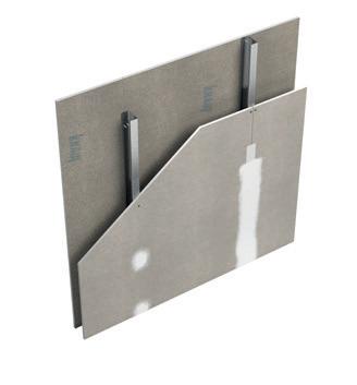
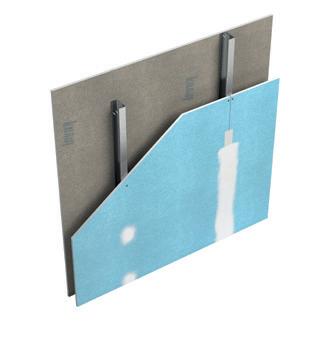
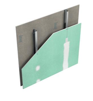
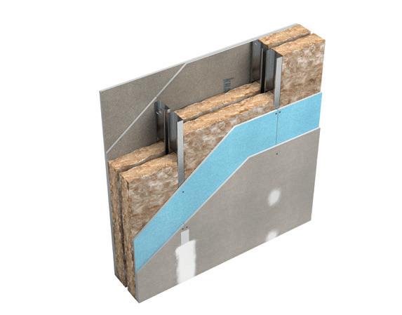
Knauf Metal Furring (MF) Suspended Ceiling Membranes
Performance tables
For further information on Knauf system performances, details and guidance on installation, please contact our Technical Services via email; technical-uk@knauf.com or call 0800 521050 (option 2).
1. The maximum height stated is for the fire resistance of the system to meet project requirements in accordance where EN compliance is required. The stated maximum height figure is the lower value between the cold state height, calculated via limiting deflection of L/240 @ 200Pa and the fire state height, as outlined in accordance with EN 1364:1 and EN 15254-3.
2. Fire resistance period
Tested in accordance with BS EN 1364-1
Fire resistance period is inclusive of both fire integrity and fire insulation. Fire resistance performance must be reviewed against Knauf specifications, standard details, with inclusion of deflection head arrangement.
3. Acoustic sound insulation
Tested or assessed in accordance with BS EN ISO 10140-1 & BS EN ISO 10140-2
Acoustic sound insulation performance based on studs at 600mm centres only
4. Fire resistance period
Tested in accordance with BS EN 1364-2
Fire resistance period is inclusive of both fire integrity and fire insulation. Fire resistance performance must be reviewed against Knauf specifications and standard details. Systems that denote N/A indicate that system has not been fire resistance tested.
Note 1. System that require fire resistance and/or acoustic sound insulation performance must have all outer joints taped and filled in accordance with Knauf recommendations. Systems are tested as imperforate.
Note 2: For substrate fixings, approved fixings are required to meet performance constraint. Site design team to agree the suitability of design and method of installation suitability for the project.
Isometrics of Knauf MF Suspended Ceiling Membranes
*Knauf Insulation Rocksilk ® RS45
Knauf Perfomer Partitions
1. The maximum height stated is for the fire resistance of the system to meet project requirements in accordance where EN compliance is required.
The stated maximum height figure is the lower value between the cold state height, calculated structurally to limiting deflection of L/240 @ 200Pa and the fire state height, as outlined in accordance with EN 1364-1 and EN 15254-3.
2. Fire resistance period
Tested in accordance with BS EN 1364-1
Fire resistance period is inclusive of both fire integrity and fire insulation.
Fire resistance performance must be reviewed against Knauf specifications, standard details, with inclusion of deflection head arrangement.
Systems that denote N/A indicate that system has not been fire resistance tested.
3. Acoustic sound insulation
Tested or assessed in accordance with BS EN ISO 10140-1 & BS EN ISO 10140-2
Acoustic sound insulation performance based on studs at 600mm centres only and non-deflection head arrangement.
Note 1. System that require fire resistance and/or acoustic sound insulation performance must have all outer joints taped and filled in accordance with Knauf recommendations. Systems are tested as imperforate.
Note 2. Systems designed to accommodate up to -25mm or +/-12.5mm deflection allowance. Please refer to Knauf Fire Rated Deflection Head document for detailed information on design and specification.
1. The maximum height stated is the lower value between the cold state height, calculated structurally to limiting deflection of L/240 @ 200Pa and the fire state height, as outlined in accordance with BS EN 1364-1.
2. Fire resistance period
Tested in accordance with BS EN 1364-1.
Fire resistance period is inclusive of both fire integrity and fire insulation.
Fire resistance performance must be reviewed against Knauf specifications, standard details, with inclusion of deflection head arrangement.
3. Acoustic sound insulation
Tested or assessed in accordance with BS EN ISO 10140-1 & BS EN ISO 10140-2.
Acoustic sound insulation performance based on studs at 600mm centres only and non-deflection head arrangement.
Note 1. System that require fire resistance and/or acoustic sound insulation performance must have all outer joints taped and filled in accordance with Knauf recommendations. Systems are tested as imperforate.
Note 2. Systems designed to accommodate up to -25mm or +/-12.5mm deflection allowance. Please refer to Knauf Fire Rated Deflection Head document for detailed information on design and specification.
The 100% Knauf System Performance Warranty
All of our systems are covered by our comprehesive 100% Knauf System Performance Warranty, giving you the insurance that the system you specify and install will perform to specification. Our 100% Knauf System Performance Warranty is available at system performance warranty or contact Knauf technical services - technical-uk@knauf.com or via telephone: 0800521050 (option 2).
The 100% Knauf System Performance Warranty
Knauf
Substantiated System Solutions
Knauf provides a comprehensive range of interior and exterior solutions, systems, and products, robustly tested to provide complete peace of mind for its customers. Systems have been developed and designed as complete building solutions to meet required specified performances. The systems and components are tested by accredited testing facilities in accordance with recognised industry s tandards and regulations.
The 100% Knauf System Performance Warranty guarantees that your Knauf systems are:
o Manufactured from the highest quality raw materials in state -of-the-art factories. Products comply with UK and/or EU standards and are subject to rigorous quality assurance procedures.
o System testing conducted at UKAS accredited laboratories or equivalent recognised (under ILAC MRA) European testing facilities for fire resistance and acoustic sound insulation testing with continuous factory production control testing to review and maintain published performances.
o Fully supported at every stage of the project by Knauf’s market -leading technical and sales support personnel, both pre -site and during construction.
Knauf Technical Services
Help is available via our team of ‘Technical Support Officers’ who are ready to take your technical enquiries providing you w ith expert technical advice on interior and exterior solutions to meet your project needs.
Knauf Specification Service
Tailored project specifications can be delivered with the support of highly skilled and trained Project Specification Manager s and via Knauf Planner Suite https://discover.knauf.com/en-gb/planner-suite) Knauf Planner Suite – System Finder is a three-in-one solution for simple product and system searches, immediate supporting data, and Drywall Specification Documents. Load your free planning assistan t directly in your Revit or ArchiCAD, or simply use the Knauf Planner Suite – System Finder web app.
Knauf On-Site Service
Knauf Project Technical Managers provide on -site project support to assist with the installation of Knauf systems. If Knauf product and system training is required, this can be delivered by the Knauf Technical Services Team
Customer Service
UK: 0800 521 050
Eire: 01 4620739 cservice@knauf.com
Technical Service
0800 521050 (option 2) technical-uk@knauf.com
Addresses
Knauf
Kemsley Fields Business Park Sittingbourne Kent ME9 8SR Knauf 87 Broomhill Road Tallaght Dublin 24 D24 WR85
Website knauf.com knauf.ie
Email technical-uk@knauf.com
SOCIAL MEDIA
KnaufUK
@Knauf_UK
Knauf UK & Ireland @Knauf_UK
Creation Date: 25/09/2023
Revision Reference: 011
Revision Date: 09/05/2025
The information given in this publication is believed to be current and accurate as at the date of publication, but no warranty, express or implied is given. Updates will not be automatically issued.