


This technical manual is written for an experienced technician and contains sections that are specifically for this product. It is a part of a total product support program.
The manual is organized so that all the information on a particular system is kept together. The order of grouping is as follows:
• Table of Contents
• General Diagnostic Information
• Specifications
• Electrical Wiring Harness Legend
• Component Location
• System Schematic
• Wiring Harness
• Troubleshooting Chart
• Theory of Operation
• Diagnostics
• Tests & Adjustments
• Repair
Note: Depending on the particular section or system being covered, not all of the above groups may be used.
Each section will be identified with a symbol rather than a number. The pages within a section will be consecutively numbered.
Headings in each section indicate the job being performed. A heading with no model designation applies to all the models in this manual. Headings followed by model designations apply only to those models.
Safety
Information Specifications and Engine
All information, illustrations and specifications in this manual are based on the latest information available at the time of publication. The right is reserved to make changes at any time without notice.
We appreciate your input on this manual. To help, there are postage paid post cards included at the back. If you find any errors or want to comment on the layout of the manual please fill out one of the cards and mail it back to us.
COPYRIGHT© 1998
John Deere Worldwide Commercial and Consumer Equipment Division
Horicon, Wisconsin
All rights reserved
RECOGNIZE SAFETY INFORMATION
HANDLE FLUIDS SAFELY-AVOID FIRES
Be Prepared For Emergencies
This is the safety-alert symbol. When you see this symbol on your machine or in this manual, be alert to the potential for personal injury.
Follow recommended precautions and safe servicing practices.
Understand Signal Words
A signal word—DANGER, WARNING, or CAUTION— is used with the safety-alert symbol. DANGER identifies the most serious hazards.
DANGER or WARNING safety signs are located near specific hazards. General precautions are listed on CAUTION safety signs. CAUTION also calls attention to safety messages in this manual.
REPLACE SAFETY SIGNS
When you work around fuel, do not smoke or work near heaters or other fire hazards.
Store flammable fluids away from fire hazards. Do not incinerate or puncture pressurized containers. Make sure machine is clean of trash, grease, and debris.
Do not store oily rags; they can ignite and burn spontaneously.
Be prepared if a fire starts.
Keep a first aid kit and fire extinguisher handy. Keep emergency numbers for doctors, ambulance service, hospital, and fire department near your telephone.
USE SAFE SERVICE PROCEDURES
Wear Protective Clothing
Replace missing or damaged safety signs. See the machine operator’s manual for correct safety sign placement.
Wear close fitting clothing and safety equipment appropriate to the job.
Prolonged exposure to loud noise can cause
impairment or loss of hearing. Wear a suitable hearing protective device such as earmuffs or earplugs to protect against objectionable or uncomfortable loud noises.
Operating equipment safely requires the full attention of the operator. Do not wear radio or music headphones while operating machine.
Service Machines Safely
machine. Make sure the bulb is enclosed by a wire cage. The hot filament of an accidentally broken bulb can ignite spilled fuel or oil.
Work In Ventilated Area
Tie long hair behind your head. Do not wear a necktie, scarf, loose clothing, or necklace when you work near machine tools or moving parts. If these items were to get caught, severe injury could result.
Remove rings and other jewelry to prevent electrical shorts and entanglement in moving parts.
Use Proper Tools
Use tools appropriate to the work. Makeshift tools and procedures can create safety hazards. Use power tools only to loosen threaded parts and fasteners. For loosening and tightening hardware, use the correct size tools. DO NOT use U.S. measurement tools on metric fasteners. Avoid bodily injury caused by slipping wrenches. Use only service parts meeting John Deere specifications.
Work In Clean Area
Before starting a job:
1. Clean work area and machine.
2. Make sure you have all necessary tools to do your job.
3. Have the right parts on hand.
4. Read all instructions thoroughly; do not attempt shortcuts.
Using High Pressure Washers
Directing pressurized water at electronic/electrical components or connectors, bearings, hydraulic seals, fuel injection pumps or other sensitive parts and components may cause product malfunctions. Reduce pressure and spray at a 45 to 90 degree angle.
Illuminate Work Area Safely
Illuminate your work area adequately but safely. Use a portable safety light for working inside or under the
Engine exhaust fumes can cause sickness or death. If it is necessary to run an engine in an enclosed area, remove the exhaust fumes from the area with an exhaust pipe extension.
If you do not have an exhaust pipe extension, open the doors and get outside air into the area.
WARNING: California Proposition 65 Warning
Diesel engine exhaust and some of its constituents are known to the State of California to cause cancer, birth defects, and other reproductive harm.
Gasoline engine exhaust from this product contains chemicals known to the State of California to cause cancer, birth defects, or other reproductive harm.
Remove Paint Before Welding Or Heating
Avoid potentially toxic fumes and dust. Hazardous fumes can be generated when paint is heated by welding, soldering, or using a torch. Do all work outside or in a well ventilated area. Dispose of paint and solvent properly. Remove paint before welding or heating: If you sand or grind paint, avoid breathing the dust. Wear an approved respirator. If you use solvent or paint stripper, remove stripper with soap and water before welding. Remove solvent or paint stripper containers and other flammable material from area. Allow fumes to disperse at least 15 minutes before welding or heating.
Avoid Harmful Asbestos Dust
Avoid breathing dust that may be generated when handling components containing asbestos fibers. Inhaled asbestos fibers may cause lung cancer. Components in products that may contain asbestos fibers are brake pads, brake band and lining assemblies, clutch plates, and some gaskets. The asbestos used in these components is usually found in a resin or sealed in some way. Normal handling is not hazardous as long as airborne dust containing
asbestos is not generated.
Avoid creating dust. Never use compressed air for cleaning. Avoid brushing or grinding material containing asbestos. When servicing, wear an approved respirator. A special vacuum cleaner is recommended to clean asbestos. If not available, apply a mist of oil or water on the material containing asbestos. Keep bystanders away from the area.
AVOID INJURY FROM ROTATING BLADES, AUGERS & PTO SHAFTS
Dispose of Waste Properly
Improperly disposing of waste can threaten the environment and ecology. Potentially harmful waste used with John Deere equipment include such items as oil, fuel, coolant, brake fluid, filters, and batteries. Use leakproof containers when draining fluids. Do not use food or beverage containers that may mislead someone into drinking from them. Do not pour waste onto the ground, down a drain, or into any water source. Inquire on the proper way to recycle or dispose of waste from your local environmental or recycling center, or from your John Deere dealer.
LIVE WITH SAFETY
Keep hands and feet away while machine is running. Shut off power to service, lubricate or remove mower blades, augers or PTO shafts.
HANDLE CHEMICAL PRODUCTS SAFELY
Before returning machine to customer, make sure machine is functioning properly, especially the safety systems. Install all guards and shields.
Direct exposure to hazardous chemicals can cause serious injury. Potentially hazardous chemicals used with John Deere equipment include such items as lubricants, coolants, paints, and adhesives.
A Material Safety Data Sheet (MSDS) provides specific details on chemical products: physical and health hazards, safety procedures, and emergency response techniques. Check the MSDS before you start any job using a hazardous chemical. That way you will know exactly what the risks are and how to do the job safely. Then follow procedures and recommended equipment.
GENERAL SPECIFICATIONS
METRIC FASTENER TORQUE VALUES
DO NOT use these hand torque values if a different torque value or tightening procedure is given for a specific application. Torque values listed are for general use only and include a ±10% variance factor. Check tightness of fasteners periodically. DO NOT use air powered wrenches.
Shear bolts are designed to fail under predetermined loads. Always replace shear bolts with identical grade. Fasteners should be replaced with the same class. Make sure fastener threads are clean and that you properly start thread engagement. This will prevent them from failing when tightening.
When bolt and nut combination fasteners are used, torque values should be applied to the NUT instead of the bolt head.
Tighten toothed or serrated-type lock nuts to the full torque value.
a “Lubricated” means coated with a lubricant such as engine oil, or fasteners with phosphate and oil coatings. “Dry” means plain or zinc plated (yellow dichromate - Specification JDS117) without any lubrication
Reference: JDS—G200.
INCH FASTENER TORQUE VALUES
DO NOT use these hand torque values if a different torque value or tightening procedure is given for a specific application. Torque values listed are for general use only and include a ±10% variance factor. Check tightness of fasteners periodically. DO NOT use air powered wrenches.
Shear bolts are designed to fail under predetermined loads. Always replace shear bolts with identical grade. Fasteners should be replaced with the same grade. Make sure fastener threads are clean and that you properly start thread engagement. This will prevent them from failing when tightening.
When bolt and nut combination fasteners are used, torque values should be applied to the NUT instead of the bolt head.
Tighten toothed or serrated-type lock nuts to the full torque value.
a “Lubricated” means coated with a lubricant such as engine oil, or fasteners with phosphate and oil coatings. “Dry” means plain or zinc plated (yellow dichromate - Specification JDS117) without any lubrication
b “Grade 2” applies for hex cap screws (not hex bolts) up to 152 mm (6-in.) long. “Grade 1” applies for hex cap screws over 152 mm (6-in.) long, and for all other types of bolts and screws of any length.
JDS—G200.
GASOLINE2–CYCLE ENGINES - NORTH AMERICA
CAUTION
Gasoline is HIGHLY FLAMMABLE, handle it with care.
DO NOT refuel machine while:
• indoors, always fill gas tank outdoors;
• machine is near an open flame or sparks;
• engine is running, STOP engine;
• engine is hot, allow it to cool sufficiently first;
• smoking.
Help prevent fires:
• fill gas tank to bottom of filler neck only;
• be sure fill cap is tight after fueling;
• clean up any gas spills IMMEDIATELY;
• keep machine clean and in good repair–free of excess grease, oil, debris, and faulty or damaged parts;
• any storage of machines with gas left in tank should be in an area that is well ventilated to prevent possible igniting of fumes by an open flame or spark, this includes any appliance with a pilot light.
To prevent fire or explosion caused by STATIC ELECTRIC DISCHARGE during fueling:
• ONLY use a clean, approved POLYETHYLENE PLASTIC fuel container and funnel WITHOUT any metal screen or filter.
To avoid engine damage:
• ONLY use fresh, clean, unleaded gasoline with an octane rating (anti-knock index) of 87 or higher;
• mix in John Deere 2-Cycle Engine Oil or its equivalent using a 50:1 fuel/oil mixture (see 2Cycle Gasoline Engine Oil in this section);
• if John Deere 2-Cycle Engine Oil or its equivalent IS NOT being used, mix alternative 2-cycle engine oil to a 32:1 fuel/oil mixture (see 2-Cycle Gasoline Engine Oil in this section).
Use of alternative oxygenated, gasohol blended, unleaded gasoline is acceptable as long as:
• the ethyl or grain alcohol blends DO NOT exceed 10% by volume or
• methyl tertiary butyl ether (MTBE) blends DO NOT exceed 15% by volume.
WARNING
California Proposition 65 Warning: Gasoline engine exhaust from this product contains chemicals known to the State of California to cause cancer, birth defects, or other reproductive harm.
GASOLINE STORAGE
IMPORTANT: Keep all dirt, scale, water or other foreign material out of gasoline.
IMPORTANT: DO NOT use METHANOL gasolines because METHANOL is harmful to the environment and to your health.
Keep gasoline stored in a safe, protected area. Storage of gasoline in a clean, properly marked (“UNLEADED GASOLINE”) POLYETHYLENE PLASTIC container WITHOUT any metal screen or filter is recommended. DO NOT use de-icers to attempt to remove water from gasoline or depend on fuel filters to remove water from gasoline. Use a water separator installed in the storage tank outlet. BE SURE to properly discard unstable or contaminated gasoline. When storing unit or gasoline, it is recommended that you add John Deere Gasoline Conditioner and Stabilizer (TY15977) or an equivalent to the gasoline. BE SURE to follow directions on container and to properly discard empty container.
2–CYCLE ENGINES - EUROPE
CAUTION
Gasoline is HIGHLY FLAMMABLE, handle it with care.
DO NOT refuel machine while:
• indoors, always fill gas tank outdoors;
• machine is near an open flame or sparks;
• engine is running, STOP engine;
• engine is hot, allow it to cool sufficiently first;
• smoking.
Help prevent fires:
• fill gas tank to bottom of filler neck only;
• be sure fill cap is tight after fueling;
• clean up any gas spills IMMEDIATELY;
• keep machine clean and in good repair–free of excess grease, oil, debris, and faulty or damaged parts;
• any storage of machines with gas left in tank should be in an area that is well ventilated to prevent possible igniting of fumes by an open flame or spark, this includes any appliance with a pilot light.
To prevent fire or explosion caused by STATIC ELECTRIC DISCHARGE during fueling:
• ONLY use a clean, approved POLYETHYLENE PLASTIC fuel container and funnel WITHOUT any metal screen or filter.
To avoid engine damage:
• ONLY use fresh, clean, unleaded gasoline with an octane rating (anti-knock index) of 87 or higher;
• mix in John Deere 2-Cycle Engine Oil or its equivalent using a 50:1 fuel/oil mixture (see 2Cycle Gasoline Engine Oil in this section);
• if John Deere 2-Cycle Engine Oil or its equivalent IS NOT being used, mix alternative 2-cycle engine oil to a 32:1 fuel/oil mixture (see 2-Cycle Gasoline Engine Oil in this section).
Use of alternative oxygenated, gasohol blended, unleaded gasoline is acceptable as long as:
• the ethyl or grain alcohol blends DO NOT exceed 10% by volume or
• methyl tertiary butyl ether (MTBE) blends DO NOT exceed 15% by volume.
GASOLINE STORAGE
IMPORTANT: Keep all dirt, scale, water or other foreign material out of gasoline. Keep gasoline stored in a safe, protected area. Storage of gasoline in a clean, properly marked (“UNLEADED GASOLINE”) POLYETHYLENE PLASTIC container WITHOUT any metal screen or filter is recommended. DO NOT use de-icers to attempt to remove water from gasoline or depend on fuel filters to remove water from gasoline. Use a water separator installed in the storage tank outlet. BE SURE to properly discard unstable or contaminated gasoline. When storing unit or gasoline, it is recommended that you add John Deere Gasoline Conditioner and Stabilizer (TY15977) or an equivalent to the gasoline. BE SURE to follow directions on container and to properly discard empty container.
IMPORTANT: DO NOT use METHANOL gasolines because METHANOL is harmful to the environment and to your health.
2–CYCLE GASOLINE ENGINE OILNORTH AMERICA
IMPORTANT: Mix unleaded gasoline (87 octane or higher) and John Deere 2-Cycle Engine Oil to a 50:1 ratio (3.8 L [1 U.S. gal] gasoline to 76 ml [2.6 oz.] oil or 4.5 L [1 Imperial gal] gasoline to 90 ml [3.0 oz.] oil).
If John Deere 2-Cycle Engine Oil or its equivalent IS NOT being used mix unleaded gasoline and alternative 2-cycle engine oil to a 32:1 ratio (3.8 L [1 U.S. gal] gasoline to 119 ml [4.0 oz.] oil or 4.5 L [1 Imperial gal] gasoline to 141 ml [4.8 oz.] oil).
The following John Deere oil is PREFERRED:
• 2-CYCLE ENGINE OIL. Other oils may be used if above preferred John Deere oil is not available, provided they meet one of the following specifications:
• SAE Standard J2116 or Classifications TA, TB, TC, or TD;
• API Classification TC or higher;
• NMMA Classifications TC-W or TC-WII or higher;
• JASO Classifications FA, FB, or FC or higher. John Deere Dealers: You may want to cross-reference the following publications to recommend the proper oil for your customers:
• Module DX,GAS2 in JDS–G135;
• Section 530, Lubricants & Hydraulics, of the John Deere Merchandise Sales Guide;
• Lubrication Sales Manual PI7032.
2–CYCLE GASOLINE ENGINE OILEUROPE
IMPORTANT: Mix unleaded gasoline (87 octane or higher) and John Deere 2-Cycle Engine Oil to a 50:1 ratio (3.8 L [1 U.S. gal] gasoline to 76 ml [2.6 oz.] oil or 4.5 L [1 Imperial gal] gasoline to 90 ml [3.0 oz.] oil).
If John Deere 2-Cycle Engine Oil or its equivalent IS NOT being used mix unleaded gasoline and alternative 2-cycle engine oil to a 32:1 ratio (3.8 L [1 U.S. gal] gasoline to 119 ml [4.0 oz.] oil or 4.5 L [1 Imperial gal] gasoline to 141 ml [4.8 oz.] oil).
The following John Deere oil is PREFERRED:
• 2–CYCLE ENGINE OIL.
Other oils may be used if above preferred John Deere oil is not available, provided they meet one of the following specifications:
• SAE Standard J2116 or Classifications TA, TB, TC or TD;
• API Classification TC or higher;
• NMMA Classifications TC-W or TC-WII or higher;
• JASO Classifications FA, FB, or FC or higher;
• CEC Standard L-19-T-77.
John Deere Dealers: You may want to cross-reference the following publications to recommend the proper oil for your customers:
• Module DX,GAS2 in JDS–G135;
• Section 530, Lubricants & Hydraulics, of the John Deere Merchandise Sales Guide.
ALTERNATIVE LUBRICANTSNORTH AMERICA
Conditions in certain geographical areas outside the United States and Canada may require different lubricant recommendations than the ones printed in this technical manual or the operator's manual. Consult with your John Deere Dealer, or Sales Branch, to obtain the alternative lubricant recommendations.
IMPORTANT: Use of alternative lubricants could cause reduced life of the component.
If alternative lubricants are to be used, it is recommended that the factory fill be thoroughly removed before switching to any alternative lubricant.
SYNTHETIC LUBRICANTS
Synthetic lubricants may be used in John Deere equipment if they meet the applicable performance requirements (industry classification and/or military specification) as shown in this manual.
The recommended air temperature limits and service or lubricant change intervals should be maintained as shown in the operator’s manual, unless otherwise stated on lubricant label.
Avoid mixing different brands, grades, or types of oil. Oil manufacturers blend additives in their oils to meet certain specifications and performance requirements. Mixing different oils can interfere with the proper functioning of these additives and degrade lubricant performance.
LUBRICANT STORAGE
All machines operate at top efficiency only when clean lubricants are used. Use clean storage containers to handle all lubricants. Store them in an area protected from dust, moisture, and other contamination. Store drums on their sides. Make sure all containers are properly marked as to their contents. Dispose of all old, used containers and their contents properly.
MIXING OF LUBRICANTS
In general, avoid mixing different brands or types of lubricants. Manufacturers blend additives in their lubricants to meet certain specifications and performance requirements. Mixing different lubricants can interfere with the proper functioning of these additives and lubricant properties which will downgrade their intended specified performance.
John Deere Dealers: You may want to cross-reference the following publications to recommend the proper oil filter for your customers:
• Module DX,FILT in JDS–G135;
• Section 540, Lubricants & Hydraulics, of the John Deere Merchandise Sales Guide;
• Lawn & Grounds Care Tune-Up Guide PI672.
ALTERNATIVE LUBRICANTSEUROPE
Conditions in certain geographical areas outside the United States and Canada may require different lubricant recommendations than the ones printed in this technical manual or the operator's manual. Consult with your John Deere Dealer, or Sales Branch, to obtain the alternative lubricant recommendations.
IMPORTANT: Use of alternative lubricants could cause reduced life of the component.
If alternative lubricants are to be used, it is recommended that the factory fill be thoroughly removed before switching to any alternative lubricant.
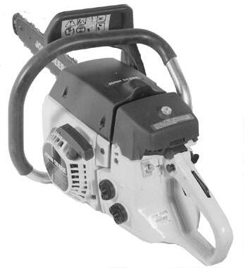
PRODUCT IDENTIFICATION NUMBERS
MODEL 200CS & 230CS
MODEL 300CS
Product Identification Data Plate
Product identification plate is located under the handle near the start switch on the rear of the main case.
Product Identification Data Plate
Product identification plate is located under the handle near the start switch on the rear of the main case.
MODEL 500CS
Product Identification Data Plate
Product identification plate is located on the rear of the main case.
Thank you very much for your reading. Please Click Here. Then Get COMPLETE MANUAL.NOWAITING

NOTE:
If there is no response to click on the link above, please download the PDF document first and then clickonit.
SPECIFICATIONS
TIGHTENING TORQUES—200CS AND 230CS
a. Use 242 LOCTITE® Thread Locking Compound
b. Use 290 LOCTITE® High Temperature Thread Locking Compound
c. Use FEL-PRO® C5-A Anti-Seize Or Equivalent On These Fasteners
d. Use 277 LOCTITE®High Strength Thread Locking Compound
e. Use 12666 LOCTITE®Anerobic Sealant And Gasketing Compound