
Previous Screen
Product: WHEEL LOADER
Model: 924G WHEEL LOADER WMB
Configuration: 924G 924Gz Wheel Loader WMB00001-UP (MACHINE) POWERED BY 3056E Engine
Disassembly and Assembly
IT28G Integrated Toolcarrier and 924G, 924GZ and 928G Wheel Loaders Power Train
Transmission and Torque Converter - Assemble
SMCS - 3001-016
Assembly Procedure
Table 1 Required Tools
Note: Cleanliness is an important factor. Before assembly, all parts should be thoroughly cleaned in cleaning fluid. Allow the parts to air dry. Wiping cloths or rags should not be used to dry parts Lint may be deposited on the parts which may cause later trouble. Inspect all parts. If any parts are worn or damaged, use new parts for replacement.
Illustration 1
g01005243
1. Install gear (149) and retaining ring (148) . Raise the temperature of bearing cone (147) . Install bearing cone (147) .

Illustration 2
g01005241
2. Raise the temperature of bearing cone (146) . Install bearing cone (146) .

3. Apply Tooling (L) to the seal bore.
4. Install lip seal (145) . Lubricate the sealing lip with the lubricant that is being used.
5. Lower the temperature of bearing cup (143) . Install bearing cup (143) .
6. Use bolts (142) in order to install shield assembly (144) . Tighten bolts (142) to a torque of 55 ± 10 N·m (40 ± 10 lb ft).


g01005238
7. Install the output shaft and gear (141) .
Illustration 3 g01005239 Illustration 48. Install lip seal (140) . Lubricate the sealing lip with the lubricant that is being used.
9. Lower the temperature of bearing cup (139) . Install bearing cup (139) .


10. Install seal (138) .
11. Install shims (137) . Use the shims in order to get 0.06 mm (0.002 inch) to 0.13 mm (0.005 inch) end play on the output shaft.
Note: Lubricate the bore of the housing with the lubricant that is being used.
Illustration 5 g01005236 Illustration 6 g00655180 12. Use bolts (135) in order to install the cage. Tighten bolts (135) to a torque of 70 ± 10 N·m (50 ± 10 lb ft).g00890758
13. Install parking brake assembly (133) and lever (134) .
14. Use bolts (131) in order to install plate (132) . Tighten bolts (131) to a torque of 120 ± 20 N·m (90 ± 15 lb ft).

g00890622
15. Install brake drum (130) and yoke (129) together. Install seal (128) .
 Illustration 7
Illustration 8
Illustration 7
Illustration 8
Illustration 9 g00685060
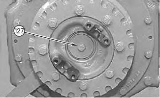
16. Install the bolt and washer (127) . Tighten bolt (127) to a torque of 120 ± 20 N·m (90 ± 15 lb ft).
Illustration 10 g00655120
17. Use washer (125) and bolt (124) in order to install yoke (126) . Tighten bolt (124) to a torque of 120 ± 20 N·m (90 ± 15 lb ft).

Illustration 11 g00655110
18. Lower the temperature of bearing cups (123) . Install bearing cups (123) . Use Tooling (J) to install bearing (122) .

g00890621
19. Install gear (119) . Raise the temperature of bearing cone (118) . Install bearing cone (118) .

20. Install gear (120) . Raise the temperature of bearing cone (121) . Install bearing cone (121) .


21. Install seal (116) on carrier (117) and install carrier (117) .
g00655016
Illustration 12 Illustration 13 22. Install the input shaft assembly (115) .Illustration 14
23. Install seals (112) , (113) , and (114) .
g00654969
Illustration 15 g00654966
Note: Lubricate the piston, and the bore with clean transmission oil.
24. Use Tooling (P) in order to install piston (111) .


Illustration 16
Improper assembly of parts that are spring loaded can cause bodily injury.
To prevent possible injury, follow the established assembly procedure and wear protective equipment.
g00654842Install spring (110) .
Put the clutch pack in a suitable press. Use Tooling (H) in order to install retaining ring


Illustration 19
g00654824
28. Lower the temperature of bearing assembly (107) . Install bearing assembly (107) .


Illustration 20
29. Install ring (106) .
g00654818
Illustration 21
g00890619
Note: Refer to Specifications, "Power Shift Transmission" for the specifications of the clutch discs.
30. Install plates and discs (105) . Install retaining ring (103) . Install washers (104) and (102) .
31. Install hub assembly (101) .
32. Install gear (100) and retaining ring (99) . Install washer (98) .

 Illustration 22 g00654724
Illustration 23
g00654719
Illustration 22 g00654724
Illustration 23
g00654719
Illustration 24
g00656434
33. Install gear (95) and washer (96) . Raise the temperature of bearing (97) . Install bearing (97) .


Note: This completes the assembly of the first gear clutch pack.
Note: Refer to Specifications, "Power Shift Transmission" for the procedure to measure running clearance.
Illustration 25
34. Install seals (94) and (93) .
g00654638
Illustration 26
g00890838
Note: Lubricate the piston, and the bore with clean transmission oil.
35. Use Tooling (P) in order to install piston (90) .


36. Install seals (92) on shaft (91) .
Illustration 27
37. Install spring (89) and retainer (88) .
g00654534
Illustration 28
g00654525
Improper assembly of parts that are spring loaded can cause bodily injury.
To prevent possible injury, follow the established assembly procedure and wear protective equipment.
38. Put the third gear clutch pack in a suitable press. Use Tooling (H) in order to install retaining ring (87) .

Illustration 29
g00654519
Note: Refer to Specifications, "Power Shift Transmission" for the specifications of the clutch discs.
39. Install plates and discs (86) . Install retaining ring (85) .
40. Install washer (84) .
Illustration 30 g00654517
41. Use a suitable press in order to install bearing (83) . Install retaining ring (82) .


Illustration 31 g00654512
42. Install hub assembly (81) .
Illustration 32 g00654507
43. Install gear (80) and retaining ring (79) .
Illustration 33
g00654497
44. Install washer (78) and retaining ring (77) .
Note: This completes the assembly of the third gear clutch pack.
Note: Refer to Specifications, SENR3504, "Power Shift Transmission" for the procedure to measure running clearance .

Illustration 34
g00654494
45. Use Tooling (D) in order to install third gear clutch pack (76) . The weight of third gear clutch pack (76) is approximately 50 kg (110 lb).

Note: Use Steps 46 through 49 for the assembly of the clutch of the second gear clutch pack. Use Tooling (E) in step 49 instead of Tooling (H) .
46. Install washers (75) and (74) . Install spacer (73) .
47. Install gear (72) , spacer (70) , and bearing cone (71) .
 Illustration 35 g00890612
Illustration 36 g00654403
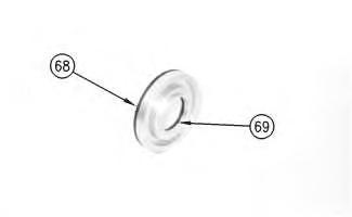
48. Install seals (69) and (68) .
Illustration 35 g00890612
Illustration 36 g00654403
48. Install seals (69) and (68) .
Illustration 37 g00890841
Illustration 38 g00654372
Note: Lubricate the piston and the bore with clean transmission oil.
49. Use Tooling (P) in order to install piston (65) . Install seals (66) on shaft (67) .


 Illustration 39 g00654364
50. Install spring (64) and retainer (63) .
Illustration 39 g00654364
50. Install spring (64) and retainer (63) .
Illustration 40
g00654360
Improper assembly of parts that are spring loaded can cause bodily injury.
To prevent possible injury, follow the established assembly procedure and wear protective equipment.
51. Put the reverse clutch pack in a suitable press. Use Tooling (H) in order to install retaining ring (62) .
Illustration 41
g00890611
52. Use a suitable press in order to install bearing (61) . Install retaining ring (60) .


Illustration 42
g00890610
Note: Refer to Specifications, "Power Shift Transmission" for the specifications of the clutch discs.


53. Install plates and discs (59) . Install retaining ring (57) .
54. Install washer (58) .
Illustration 43
g00654347
55. Install hub assembly (56) .Illustration 44
56. Install gear (55) and retaining ring (54) .


g00654328
Illustration 45
g00654339
57. Install washer (53) and retaining ring (52) .
Note: This completes the assembly of the reverse second gear clutch pack.
Note: Refer to Specifications, "Power Shift Transmission" for the procedure to measure running clearance.
Illustration 46 g00654301
58. Use Tooling (D) in order to install reverse second gear clutch pack (51) . The weight of reverse second gear clutch pack (51) is approximately 32 kg (70 lb).


Illustration 47 g00654292
59. Install seals (49) and (50) .
Illustration 48 g00654280

Note: Lubricate the piston, and the bore with clean transmission oil.
60. Use Tooling (P) in order to install piston (47) .
61. Install spring (46) and retainer (45) .
Improper assembly of parts that are spring loaded can cause bodily injury.
To prevent possible injury, follow the established assembly procedure and wear protective equipment.
62. Put the forward high clutch pack in a suitable press. Use Tooling (H) in order to install retaining ring (44) .

 Illustration 49
g00654276
Illustration 49
g00654276
Illustration 50
g00654274
Note: Refer to Specifications, "Power Shift Transmission" for specifications of the clutch discs.
63. Install plates and discs (43) . Install retaining ring (42) . Install washer (41) .
Illustration 51 g00654263
64. Use a suitable press in order to install bearing (40) . Install retaining ring (39) .


Illustration 52 g00654261
65. Install hub (38) .
g00654253
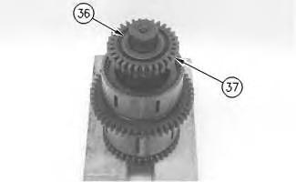
66. Raise the temperature of gear (37) . Install gear (37) . Install retaining ring (36) .

g00654078
67. Install washer (35) and retaining ring (34) .
Note: This completes the assembly of the forward high gear clutch pack.
Note: Refer to Specifications, "Power Shift Transmission" for the procedure to measure running clearance.
Illustration 53 Illustration 54Illustration 55
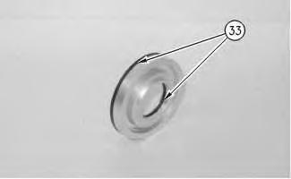
68. Install O-ring seals (33) .
g00654063
Illustration 56
g00890845
Note: Lubricate the piston, and the bore with clean transmission oil.
69. Use Tooling (P) in order to install piston (31) . Install seals (32) on shaft (30) .


Illustration 57
g00654029
70. Install spring (29) and retainer (28) .
Improper assembly of parts that are spring loaded can cause bodily injury.
To prevent possible injury, follow the established assembly procedure and wear protective equipment.
71. Put the forward low clutch pack in a suitable press. Use Tooling (H) in order to compress the spring. Install retaining ring (27) .
72. Use a suitable press in order to install bearing (25) . Install retaining ring (26) in hub (22) .

 Illustration 58 g00654018
Illustration 59 g00890608
Illustration 58 g00654018
Illustration 59 g00890608
Illustration 60
73. Install washer (24) .
g00653959
Illustration 61
g00890607
Note: Refer to Specifications, "Power Shift Transmission" for specifications of clutch discs.


74. Install plates and discs (23) . Install hub (21) . Install retaining ring (22) .

Thank you very much for your reading. Please Click Here. Then Get COMPLETE MANUAL.NOWAITING

NOTE:
If there is no response to click on the link above, please download the PDF document first and then clickonit.
75. Raise the temperature of gear (20) . Install gear (20) . Install retaining ring (19) .
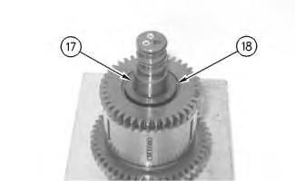
76. Install washer (18) and retaining ring (17) .
Note: This completes the assembly of the forward low gear clutch pack.
Note: Refer to Specifications, "Power Shift Transmission" for the procedure to measure running clearance.

77. Use Tooling (D) in order to install the forward low and the forward high clutch pack (15) . The weight of forward high clutch pack (15) is approximately 27 kg (60 lb).
Note: Use Tooling (J) in order to install plugs (16) .
Illustration 62 g00653932 Illustration 63 g00653893 Illustration 64 g00653858g00653848
78. Lower the temperature of bearing cups (14) . Use Tooling (K) in order to install bearing cups (14) .

g00653825
79. Use bolts (12) in order to install gear (13) . Tighten bolts (12) to a torque of 12 ± 3 N·m (10 ± 2 lb ft).

 Illustration 65
Illustration 66
Illustration 67 g00653808
Illustration 65
Illustration 66
Illustration 67 g00653808
80. Install gear assembly (10) .
81. Install O-ring seals (11) .
Illustration 68
g00653806
82. Install bolts (9) . Tighten bolts (9) to a torque of 55 ± 10 N·m (40 ± 10 lb ft).
Illustration 69
83. ApplyTooling (L) to the seal bore.
g00653801
84. Install lip seal (7) . Lubricate the sealing lip with the lubricant that is being used.

85. Install seal (8) .
