
Document Title: Function Group: Information Type: Date:

Function check, engine 200 Service Information 2014/3/31
Profile:
WLO, L330D [GB]
Function check, engine
Test possible causes
1 Initial check:
Liquid levels
Control lamps/warning lamps
Information instruments
Battery voltage
Fuses (whole, correct current)
2 Separate systems:
If two or more systems and/or circuits function together.
NOTE!
Check the system circuits individually.
3 If the machine exhibits poor rimpull, the fault may have occurred in the engine, torque converter, transmission or brakes.
Check stall speed.
If the engine stall speed is within the indicated values, the fault can be traced in the transmission, torque converter or brakes.
If the engine stall speed is low, check according to step 4.
4 Checking the engine
Check the oil and coolant for discoloration, odour, etc.
Check the exhaust pipes (internal residue)
Checking the air filter and turbo.
The engine misfires (imbalance-high noise level)
Checking for overpressure in the expansion tank.
Crankcase ventilation (overpressure-clogged)
Dipstick, remove (overpressure)
Exhaust smoke (colour-contaminants, odour).
Bleed the fuel system.
Check rpm.
Check feed pressure (before and after the filter).
Perform a compression test (repeat with oil if fault is discovered).
Check the injectors.
Check the pilot injection.
Check the diesel fuel.
Document Title: Function Group: Information Type: Date: Cylinder head, description 211 Service Information 2014/3/31
Profile:
WLO, L330D [GB]
Cylinder head, description

The engine has separate cylinder heads with one for each cylinder. The heads are made from cast iron and have replaceable guides and seats for the valves. The cylinder head has four valves per cylinder (two inlet and two exhaust valves). The inlet and exhaust ducts open out on either side of the cylinder head. The injector is positioned vertically directly above the centre of the piston crown in a thin replaceable copper sleeve which is in direct contact with the circulating coolant.

Document Title: Function Group:
Type: Date: Seal configuration (cylinder block-cylinder headcylinder liner), description
212 Service Information 2014/3/31
Profile: WLO, L330D [GB]
Seal configuration (cylinder block-cylinder head-cylinder liner), description
The seal configuration between the cylinder head and cylinder block is direct contact, i.e. there is no intermediate gasket Thus, the upper sealing surface of the cylinder liner seals directly against the cylinder head (1).

Sealing ring
Sealing ring
Sealing rings
The cylinder liner has a flame lip (2). A sealing ring (3) around the outer edge of the cylinder liner collar provides protection against external contaminants. As a seal against coolant, there is one O-ring under the cylinder liner collar (4) and three additional O-rings (5) farther down along the cylinder liner.
Document Title: Function Group: Information Type: Date: Pistons, description 213 Service Information 2014/3/31

Profile:
WLO, L330D [GB]
Pistons, description
The pistons are made of an aluminium alloy and have three piston rings. The two upper rings (1 and 2) are compression rings while the lower one (3) is an oil ring. When fit, the marking on the compression ring (letter or dot) should face up. The pistons are equipped with piston cooling. Oil is sprayed from a nozzle, which is housed in the cylinder block, into the opening of the piston cooling channel (4) on the bottom of the piston. The combustion chambers of the engine are located to the top of each piston. This formation produces an effective blend of fuel and air, resulting in efficient combustion.
Document Title: Function Group: Information Type: Date: Valve mechanism, description 214 Service Information 2014/3/31
Profile: WLO, L330D [GB]
Valve mechanism, description
The valve movement is transferred from the camshaft via roller type tappets, short pushrods, rocker arms and valve yokes to the valves.
There are four valves per cylinder (two inlet and two exhaust valves). The inlet valves have one spring each whereas the exhaust valves have double springs. The inlet and exhaust ducts open out on either side of the cylinder head. In each rocker arm there is an oil duct for lubrication of the valve yoke and the ball socket on the push rod.
Document
Crank mechanism, connecting rod,vibration damper, description
Profile: WLO, L330D [GB]
Crank mechanism, connecting rod,vibration damper, description

Crankshaft
The crankshaft, forged and tempered through nitrocarburization, is carried in seven main bearings. The front end is equipped with a so-called polygon hub to which a vibration damper is attached. The vibration damper is connected to the crankshaft. A flywheel mass is freely carried on a bushing in the vibration damper but follows the direction of rotation via a high-viscosity silicone oil.

Equalisation of the force impulses received from the cylinders occurs with the viscous silicone oil and the flywheel mass. The flywheel mass strives to maintain an even rotation speed, which in turn curbs rotation speed variations transmitted by the crankshaft.
The rear crankshaft seal is a type of lip seal. The front crankshaft seal is missing when the front crankshaft end including the vibration damper lies within the timing gear casing.
The forged connecting rods have a lubricating oil duct for pressure lubrication of the piston pin bushing. The connecting rod upper ends are trapezoidal.

 Figure 2
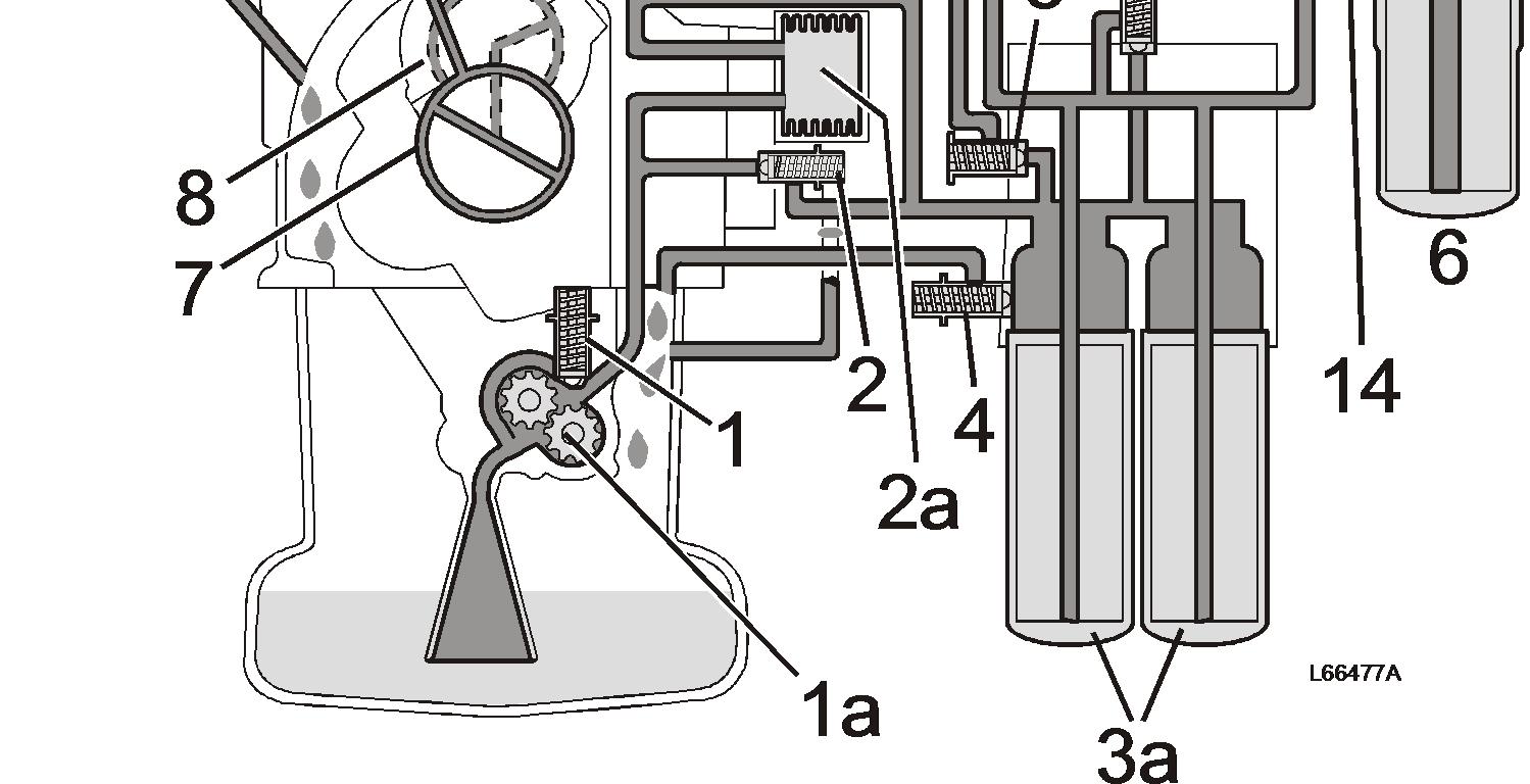
Document Title: Function Group: Information Type: Date: Lubrication system, description 220 Service Information 2014/3/31
Profile:
WLO, L330D [GB]
Lubrication system, description
The engine is pressure-lubricated from a gear pump driven by the timing gear and located on a fixed bracket in the cylinder block. The bracket also acts as one of the pump housing end plates.
The oil pump receives oil from the oil pan through an oil strainer through a suction line and forces the oil further via the fullflow filter to the various lubrication points.
The lubricating oil system includes a water-cooled oil cooler which is mounted on the cylinder block. The oil is cleaned in a partial-flow filter.
The full-flow filters are of equal capacity while the partial-flow filter is not due to the level of cleaning. The following describes the five system valves.
Safety valve. Located in the oil pump housing (1a). If the oil pressure is too high, the safety valve opens and directs the oil through a duct in the pump housing back to the pump suction line. Overflow valve. Opens when the back-pressure in the oil cooler (2a) is too high, which may occur during cold starts. The valve directs the oil past the oil cooler directly out into the system. The overflow valve for the oil filters (full-flow filters) (3a).
Both full-flow filters have a common overflow valve located on the top side of the filter head. When the overflow valve opens, the oil is directed past the oil filters, which in turn ensures engine lubrication if, for example, the filters should become clogged.
The lubricating oil pressure limiting valve is located on the side of the full-flow filter head. The valve regulates oil pressure and opens if the pressure is too high; the surplus oil is directed back to the oil pan.
Piston cooling valve. This valve is located on the top side of the full-flow filter (nearest the cylinder block).
The valve opens when the engine rpm exceeds idling speed. Oil flows through the piston cooling duct to the piston nozzles (5a). From here, the oil is injected into the ring-formed piston cooling ducts. The oil then flows further through a duct to the partial-flow filter which has a low flow volume and a high filtration value. An overflow valve for both full-flow filters ensures engine lubrication if the filters should become clogged.

Document Title: Function Group: Information Type: Date: Injectors, description 237 Service Information 2014/3/31
Profile: WLO, L330D [GB]
Injectors, description

The injectors are situated vertically in the centre of the cylinder head. The injectors break down the fuel so that there is sufficient mixture with the intake air swirls in the piston's combustion chamber.
The delivery pipes between the injection pump and the injectors are tensioned by pressure. Therefore, the pipes should under no circumstances be bent, twisted or bowed. If a delivery pipe becomes bent or otherwise deformed, it must be replaced. Otherwise there is a great risk that it will break.
Document Title: Function Group: Information Type: Date: Turbocharger, description 255 Service Information 2014/3/31
Profile:
WLO, L330D [GB]
Turbocharger, description
The turbocharger is driven by the kinetic energy in the exhausts on their way out in the exhaust system. The turbocharger consists of a turbine and compressor housing as well as a bearing housing between these.
The kinetic energy in the exhausts causes the turbine rotor to turn, the compressor rotor is mounted on the same shaft as the turbine rotor.
The compressor housing is located between the air cleaner and intercooler.
When the compressor rotor turns it draws air from the air cleaner, the air is compressed and directed to the intercooler where it's cooled before reaching the engine's cylinders.
The shaft that connects the turbine and compressor rotors is journalled in the bearing housing with floating plain bearings, which are lubricated by the engine's lubrication system
Seals of piston ring type are used to prevent the oil from leaking out of the bearing housing.
Important! Do not rev the engine immediately after start, also let the engine idle before it's stopped. This is to ensure lubrication and cooling of the turbocharger.
For many machines a rule applies that says that the engine should run at low idle for 30 seconds directly after start and before starting any work, after work the engine should run at low idle for 60 seconds. This rule is generally called 30/60.
Lubrication oil supply
Exhausts from engine, into turbocharger Exhausts, out from turbocharger


Air via air filter
Air to inlet pipe
Suggest:
If the above button click is invalid.
Please download this document first, and then click the above link to download the complete manual.
Thank you so much for reading

Document Title: Function Group: Information Type: Date: Cooling system, description 260 Service Information 2014/3/31
Profile:
WLO, L330D [GB]
Cooling system, description

Cooling system, explanatory illustration
The advantages of the system-integrated cooling system are:
Lower output losses and lower noise level as the radiator fan seldom works at maximum speed. Transmission is heated up more quickly. Oil in the hydraulic oil tank is heated, even during transport. Improved cab heat through greater hot water flow through the cab heater radiator even at low engine speed. More effective cooling of the torque converter and brakes.