
R70-20 R70-25
R70-30 R70-35
R70-40 R70-45
Treibgas-Gabelstapler
LPG Fork Truck
Chariot élévateur au GPL
Diesel-Gabelstapler
Diesel Fork Truck
Chariot élévateur Diesel
Werkstatthandbuch
Workshop manual
DFG R7032-R7034 R7048-R7050
TFG R7038-40
Ident-Nr.164537 (en)
Manuel d´Atelier
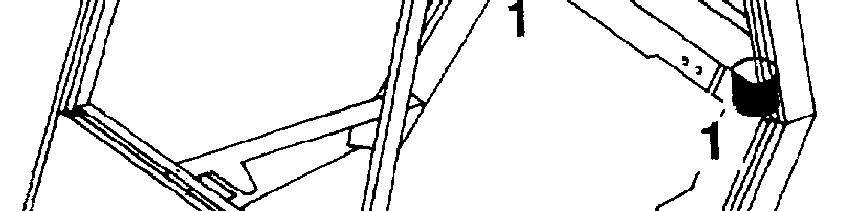
ChassisFrame
The chassis frame is constructed of electrically welded steel plate.
Detachable fuel and hydraulic oil tanks are mountedinsideleft-hand and right-hand frame sections respectivelyfor extra protection.
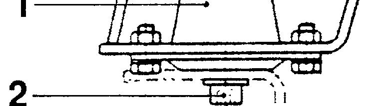
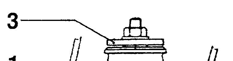
Chassis Frame and Counterweight
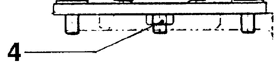
Counterweight
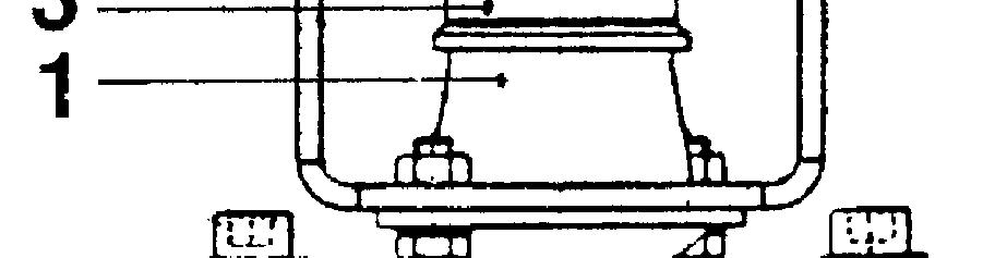
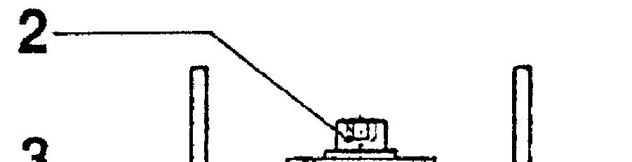
Theremovable rearcounterweightissecured to the frame weldment by 4 bolts.
1 = hex hd bolt M24x130, 8.8 DIN 933
Torqueloading:710Nm
2 = lock ring
3 = spherical washer C 25 DIN 6319
4 = ball cup D 28 DIN 6319
Weight ofthe counterweight
7032/7038 = 1,170 kg
7033/7039 = 1,514 kg
7034/7040 = 1,915 kg
7048 = 1,985 kg
7049 = 2,395 kg
7050 = 2,715 kg
Bolted to the frame at the front end and to the counterweight at the rear, the cab is mounted at 4 points on rubber typeanti-vibration mounts.
Removal

-Remove panelfromfrontcowl
-Removefloorplate

- Remove upswepttype exhaustpipe (if fitted)
- Remove cover plates leftand rightofinspection plate, giving access to the rear rubber mounts(above counterweight)
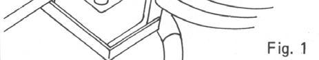
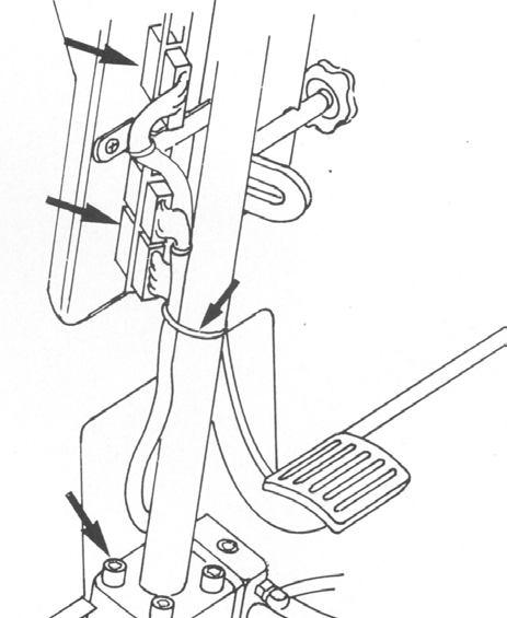
- Disconnect the 3 connectors at the steering column (Fig. 1, page 3)


- Disconnect the wiring harnessfromthe steering column
- Remove the screws which secure steering column to hand pump (steering wheel operated pump) - Fig. 1, page 3)


- Disconnectthe connectionson warning horn, brake fluid reservoir and master cylinder, located in the front cowl (Fig. 2, page 3)

Drivers cab (removal)
Detach earthing orgroundconnection
Remove panel to which is mounted the electronic control unit inside front cowl
Disconnect brake line at master cylinder (Figure 2). Refit fluid passage bolt to prevent brake fluid from flowingout

Remove M10 x80 allen screws frontand rear
Slig cab using an overhead hoistorremove cabwith the aid of a second lift truck
Stand: 2/1995 ( Ersatz für Stand: )
Workshop Manual 7032 - 34 / 38
Contents Page
Technical Data for1
MaintenanceService
Mechanical configuration ofSteeraxle
Steeraxleremoval2
Steer axle installation2
Wheelhub -Removaland3
Dismantling
Wheel hub -Reassembling and3
Installation
Wheel angle stop adjustment4
Checking the steering angles4
Stub axle- Removal and5
Dismantling
Stub axle - Reassembling and6
Installation
Lubricating the steer axle with6
grease
Trackrodremoval7
Track rodinstallation7
Steercylinderremoval8
Steer cylinder installation8
Workshop Manual 7032 - 34 / 38 - 40 / 48 - 50 02 Group Functional
Technical Data for Maintenance Service
- 38 / 34 - 7032 hub heel Wm N 225 = MA fixing xle Am N 195 = MA
heel Wm N 425 = MA for loadings Torque 50 - 7048
hub heel Wm N 470 = MA
fixing xle Am N 195 = MA
nuts heel Wm 640N = MA
Lubricants
bearings hub Wheel lithium 51825-KP2K-20 DIN to F Grease based soap
51825-KP2K-30,lithium DIN to F Grease based soap
bearings axle Stub KPF2N-20, - 51825 DIN to FL Grease based soap lithium
148659 No Ident STILL
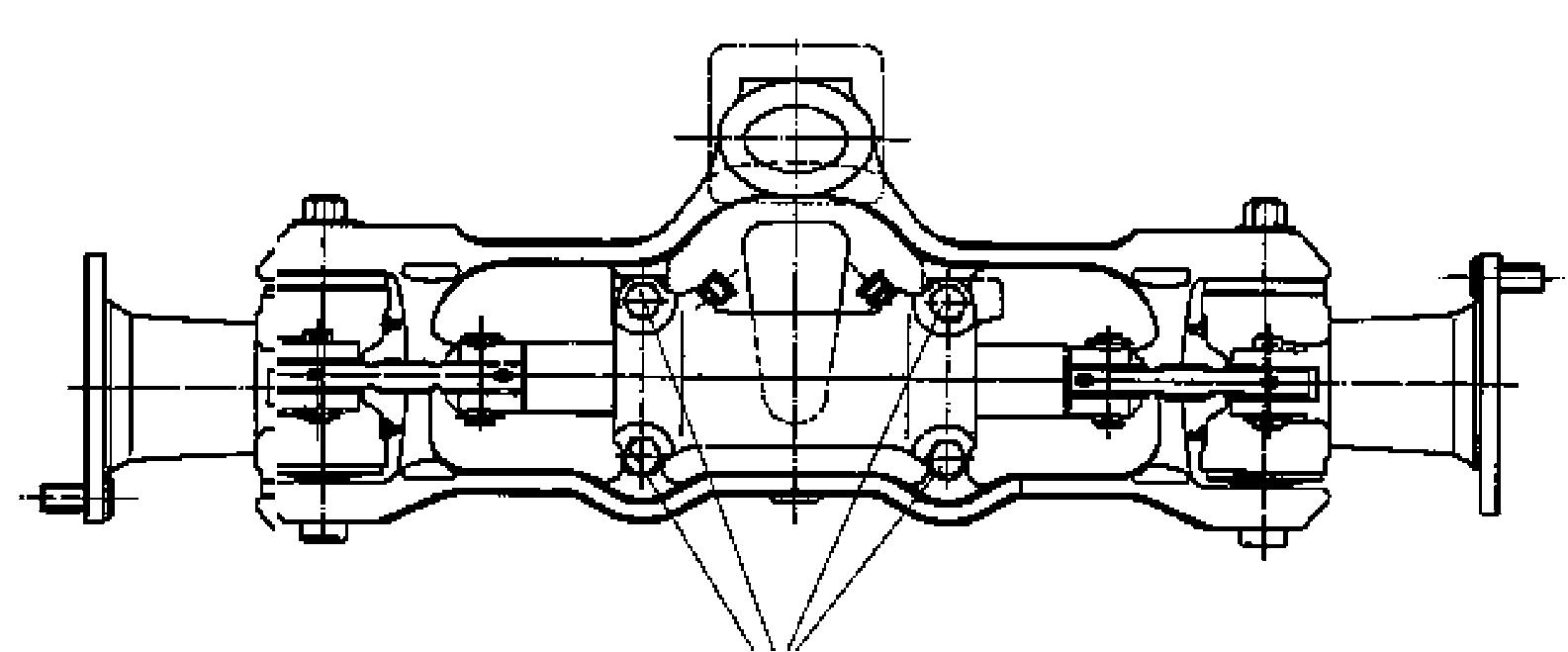
Steer axle
Configuration of steer axle
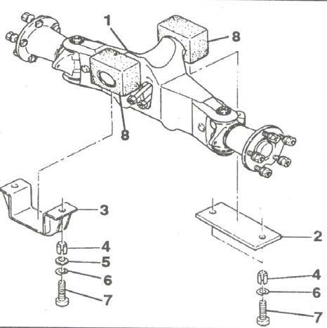
The articulating steer axle suspended from the counterweightismountedin2 neoprene blocks.The stubaxlesaresupportedintheaxlebeamontapered roller bearings.Steeringislimited bystop screwson the stub axles.
1axle beam
2+3fixing plates
4 Tension sleeve (depending on design)
5Washer(depending ondesign)
6Lock ring
7socket head screw
8neoprene blocks
Steer axle removal
CAUTION: Remove steer axle only with mast in positiononthe truck!
Riskoftipping!
-Apply the parking brake.
-Securely chock the frontwheelsto prevent rolling of the truck.
- Slacken steer wheel nuts.
- Jack up rear of the truck at counterweight (x) and place wooden blocks under the counterweight in front of the axle.
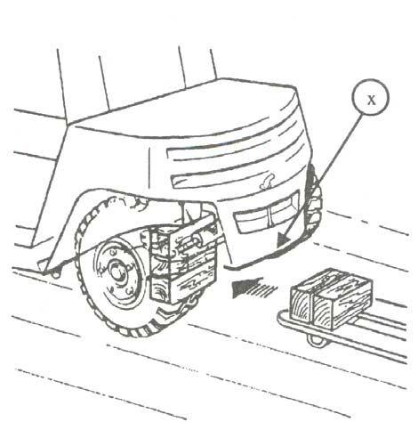
-Removewheels.
- Disconnect the hydraulic connections at steer cylinder.
CAUTION: Prepare for oil spillage when disconnectingthe hydraulic connections! Catch oil in a pan of adequate capacity and dispose of the used oil in accordance with laws and regulations.
- Remove the 4 socket head screws which retain the steer axle in place.
- Slide a hand pallet truck under the steer axle with wooden blocks placed on the fork ends of the hand pallet truck.
- Using a lever, drive steer axle outof roll pins and lower the axle onto the hand pallet truck.
Steer axle installation
-Reversetheremovalprocedure.
- The slots of the roll pins must face the direction of forward travel.
-Torque the 4 socket heads to: MA = 195 Nm
CAUTION:Donotswap hydraulicconnectionsleftand right!
Wheel hub - Removal and Dismantling
1axle beam
2stub axle
3radial sealingring
4taperedrollerbearing
5wheelhub
6rollpin
7hubcap
8nut
9washer
10taperedrollerbearing
11wheel bolt
12ball seat nut
-Slacken ball seat nuts (12) and remove wheel.
-Pull hub cap (7) from wheel.
-Slacken nut (8)
-Remove washer(9) with roll pin (6).
-Withdraw the hub.
-Removeradial sealing ring(3)then remove taperedroller bearings(4)and(10) fromhub.
-Ifnecessary,driveoutof wheel hub outer racesoftapered roller bearings(4) and (10).
Wheel hub - Reassembling and Installation
-Apply a smear of grease to the sealing lips of the radial sealingring.
-Before re-assembling the hub, repack with grease F:cavitybetween innerrace and bearing cageof tapered rollerbearings, and the bearing spaces identified by an x on the drawing.
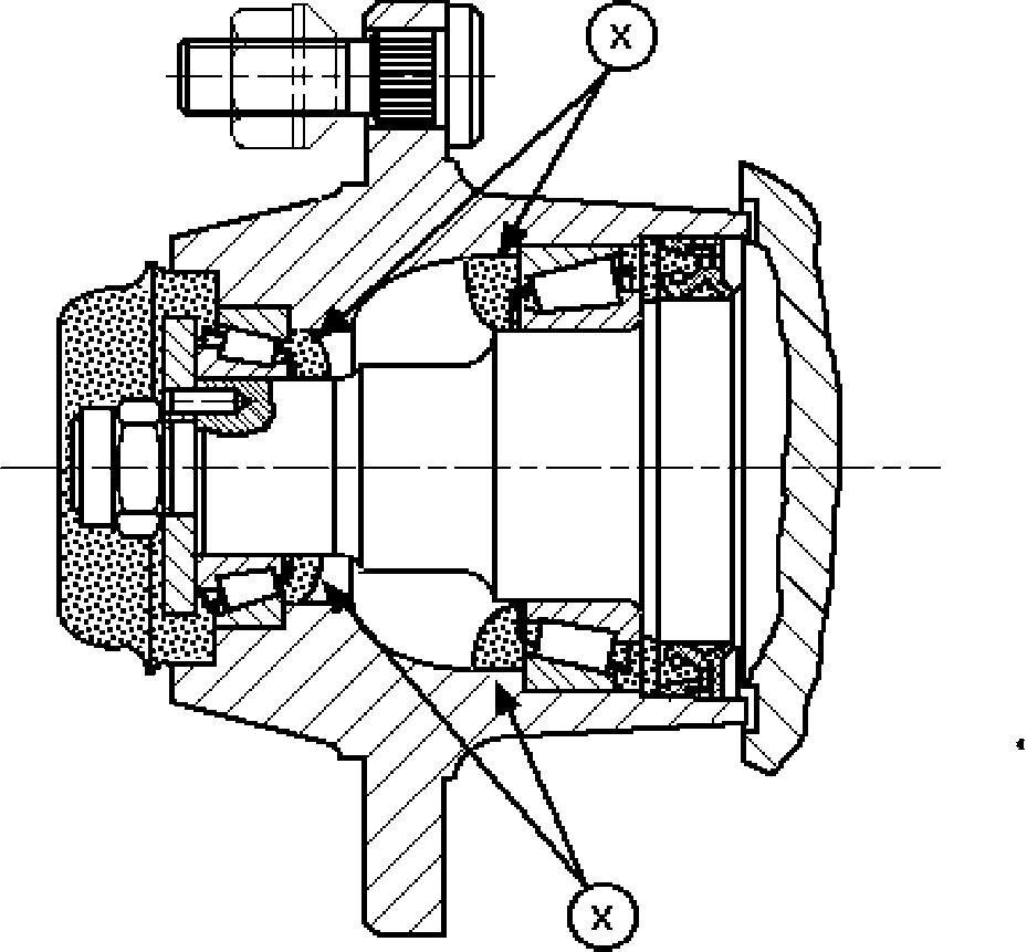
-Toreassemblethehubs,reversetheprocedure.
-Tighten nut (8) while rotating the wheel hub.
Torqueloading:
7032 - 34 / 38- 40MA = 225 Nm
7048 - 50MA = 470 Nm
Workshop Manual 7032 - 34 / 38 - 40 / 48 - 50
Steer axle
Checking the steering angles
The steering angle a must amount to 80° - 82°. Tofacilitatethemeasurementusethecomplementary anglebforthesetting.Itshouldamountto98°-100°.
IMPORTANT: Ensure that the wheel lock is limited by the stop screws (1) and not by the cylinder stroke.
Wheel angle stop adjustment
The wheel stop angle is limited by the stop screws (1).
-By operating on stop screws (1), set both steering angles to 80° - 82°.
-Check opposite angles.
-Checkforadequateclearancebetweenwheels and truck frame.
-Check that the wheel lock is not limited by the cylinder stroke.
Right-handbend
Rechtskurve
Linkskurve
= 82° +0/-2 Lenkeinschlag
Left-handbend steering lock
Stub axle - Removal and Dismantling
1nut
2washer
3king pin
4plug
5stub axle
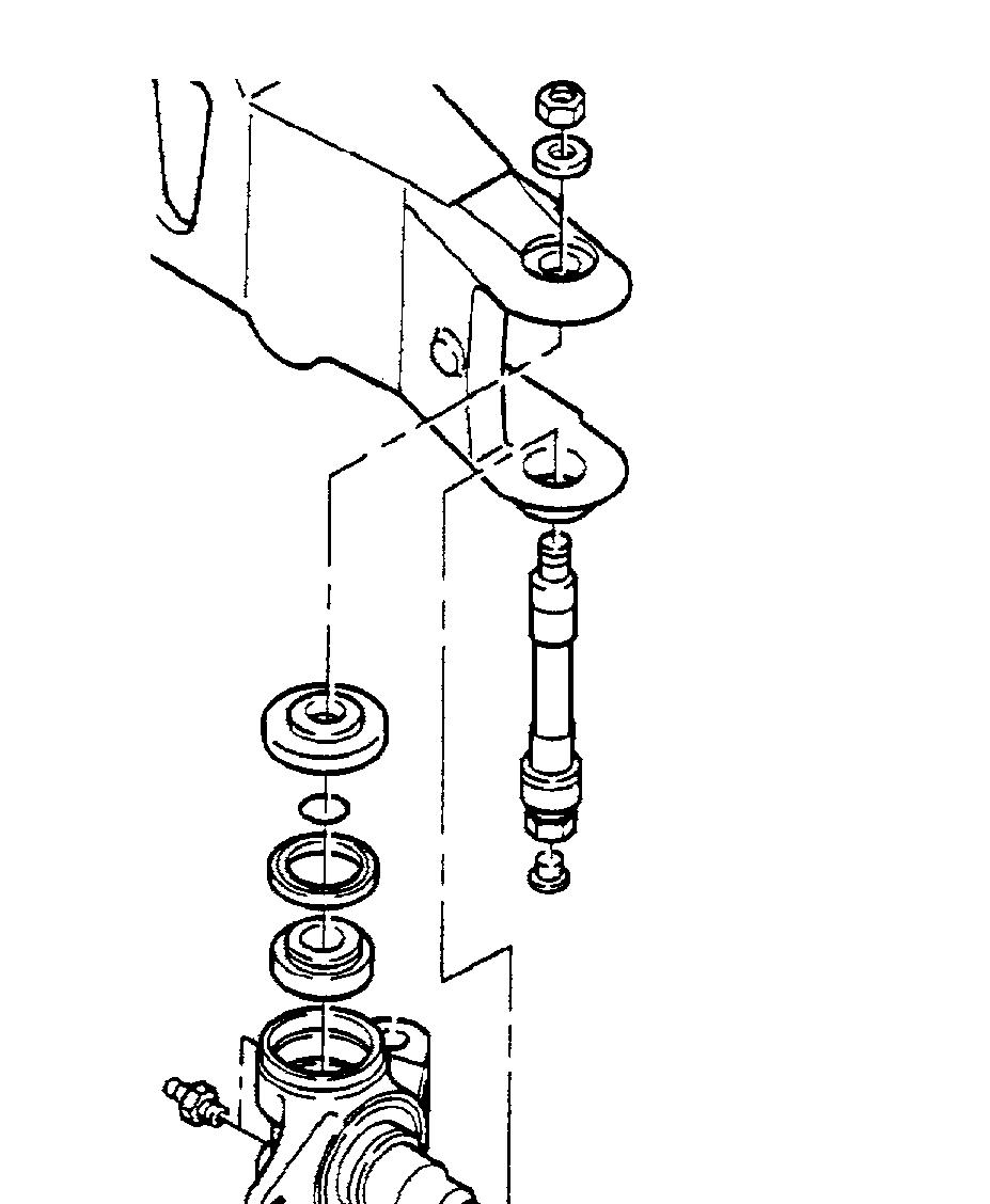
6hex. hd. screw
7nut
8spacing washer
9wiperring
10taperedrollerbearing
11spacer
12grease nipple
13taperedrollerbearing
14wiperring
15O-Ring
16spacing washer
-Removethewheel.
-Press out the pin located between track rod and stub axle.

-Slacken nut (1).
-Removewasher(2).
-Press the king pin (3) down through the stub axle and remove the king pin.
-Remove the stub axle fromthe axle.
-Remove from the stub axle:spacing washers,O ring,wiper rings,tapered roller bearings and spacer (items8-16).
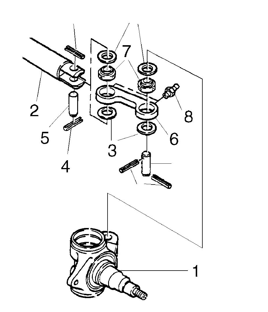
Steer axle
Stub axle - Reassembling and Installation
1nut
2washer
3king pin
4plug
5stub axle
6spacing washer
7wiperring
8taperedrollerbearing
9spacer
10taperedrollerbearing
11wiperring
12O-Ring
13spacing washer
14pin
-Insert spacer (9) into the stub axle.
-Install both tapered roller bearings (8 & 10) afterhaving first repacked themwith a sufficientamountofFL gradegrease!
-Apply a smear of FL grade grease to the sealing lips of the wiper rings (7 & 11).
-Install wiper rings(7 &11),Oring(11)aswell as both spacing washers (items 13 & 6).
-Install the stub axle into the axle beam.
-Driveinthekingpin(3)frombelowafterhaving first applied a light smear of oil to it.
-Fit the washer (2) into position on the king pin.
-Installa newnut(1) andtighten to atorqueof:
MA =290 Nm (7032-34/38-40)
MA= 310 Nm(7048-50)
-Pressthepin(14)intothetrackrodandsecure with roll pins.
-Install wheel.
-Lubricatethe steeraxlewithFL gradegrease.
Lubricating the steer axle with grease
-Operate thelinkage during steering.
-Using a grease gun, lubricate with FL grade grease the fittingswithwhich the steer axle is equippeduntila small amountoffresh grease oozes out at the lubricating points.
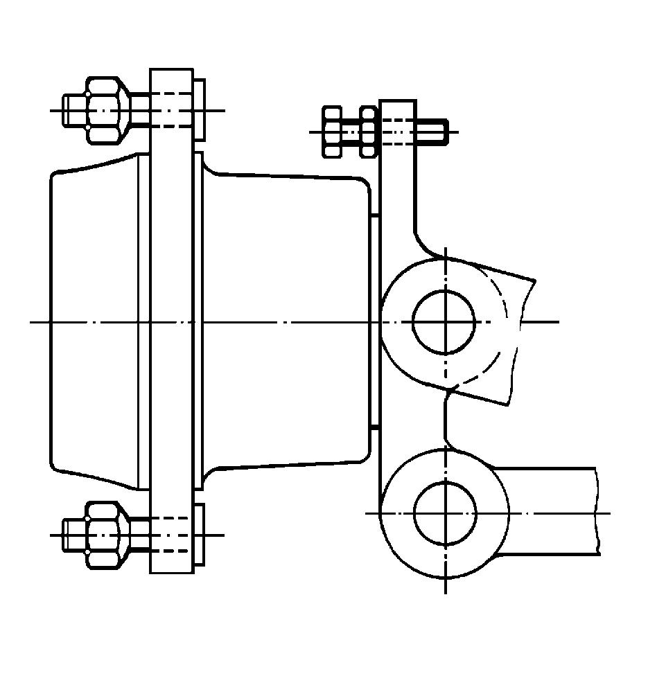
Track rod removal
The steer axle is fitted with two track rods arranged betweenthe steeringcylinderandthetwo stubaxles.
1stub axle
2piston rod
3sealingrings
4roll pins
5pin
6track rod
7ball joint
-Remove the roll pins(4).
-Using a press, press out the pins (5).
Track rod installation
-Reversetheremovalprocedure.
Installpinscylinderendwithamaximumpress forceof max. 21 kN
and pinsstub axle endwith a maximumpress forceof max. 26 kN
Steer axle
Steering cylinder removal
Remove track rods.
Disconnect hydraulic connections after having marked them for identification.
WARNING: Hydraulic oil may spill when disconnecting lines; be prepared for oil spillage!
Slacken the four fixing screws (1). . Steering cylinder installation
Retighten the fixing screws (1).
Torque loading:
MA= 210 Nm (7032-34/38-40)
MA= 295 Nm(7048-50)
Reconnect hydraulicconnections.
CAUTION:
Do notswap hydraulic connections!
Install track rods.
NOTE: For steering cylinder dismantling and reassembling refer to F.G. 06.
Lubricating the steer axle with grease
Operate the linkage during greasing while the steer axle is off load.
Using a grease gun, lubricate with FL grade grease the 8 fittings with which the steer axle is equipped until a small amount of fresh grease oozes out at the lubricating points.
NOTE: When lubricating the upper bearing, the grease need not ooze out of the upper sealing ring, it may also escape from the bottom.
Workshop Manual 7032 - 34 / 38 - 40 / 48 - 50


