
Document Title: Function Group: Information Type:
Date:
Engine, description 200 Service Information 2014/3/10
Profile:
CWL, L45B [GB]
Engine, description
Machines of SN 1941001- / -1941499 and 1951001- / -1951499 are equipped with the DEUTZ-BF4M 1013 E engine. Machines of SN 1941500- / -1943000 and 1951500- / -1953000 are equipped with the VOLVO-D5D engine. Both engines are four cylinder, four stroke, in-line direct-injected diesel engines, with exhaust turbo and liquid cooling. Machines fromSN 1943001- and 1953001- are equipped with the VOLVO-D5D engine. he engine is a four-cylinder, four-stroke, in-line diesel engine with direct injection, exhaust turbocharger, liquid cooling and internal, unregulated exhaust gas recirculation (EGR).
To comply with exhaust gas limit values, the turbocharger is equipped with unregulated, internal exhaust gas recirculation (IEGR), which returns the exhaust gas within the cylinder head to the combustion air. The oxygen content of this exhaust is low. A lower oxygen content reduces the temperature spike during combustion and thereby reduces nitrogen oxide (NO ).
The camshaft has an extra cam - the trailing cam. This causes the inlet valve to briefly open during the exhaust stroke so that exhaust gas also enters the engine intake system. In the subsequent induction stroke, this exhaust is sucked back in. There is no regulation of exhaust gas quantity.
The engine data plate specifies model, engine number and power data. The engine number is also stamped into the crankcase. Model and engine number must be specified when ordering spare parts. The direction of rotation is found on the flywheel, anticlockwise. Firing order: 1-3-4-2 (cylinder no. 1 on the flywheel side).

IMPORTANT! Adjustments to the regulator may only be performed by trained staff in an authorized central repair workshop.

Components, servicing view
Oil filler pipe Coolant pump
Fuel pump
Vibration damper
Oil filter
Engine mounting
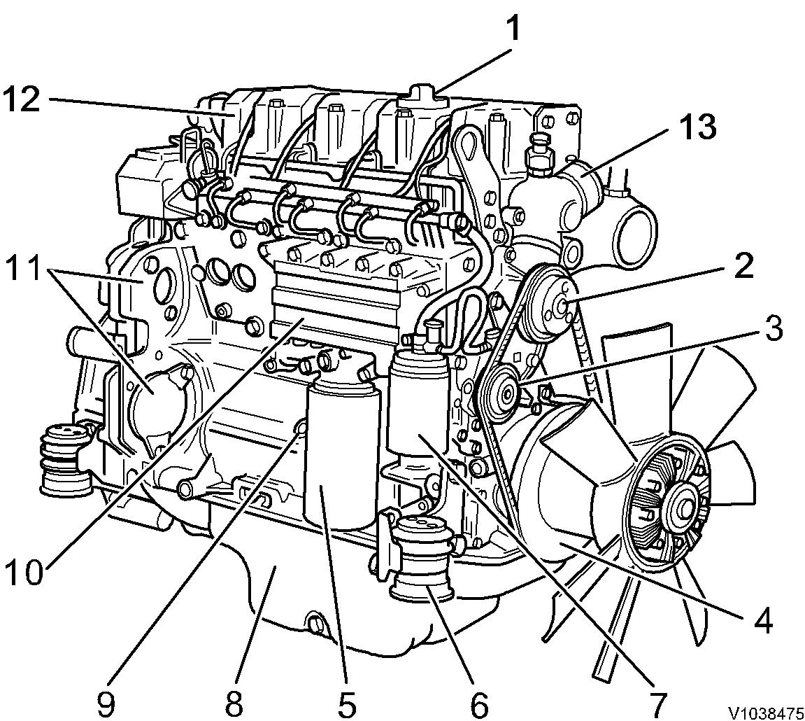
Fuel filter
Oil sump
Oil dipstick
Oil cooler
Attachment for power take-off Cylinder head Coolant supply
Components, exhaust view
Figure 2 Figure 3 Components, exhaust view
Document Title: Function Group: Information Type: Date: Compression test 210 Service Information 2014/3/10
Profile: CWL, L45B [GB]
Compression test
Op nbr 210-002
9998694 Adapter

9988539 Pressure gauge
9998007 Adapter
Injection valves are removed and valve clearance checked. Remove injection valves, see 237 Injectors all, testing and adjusting incl removing and fitting
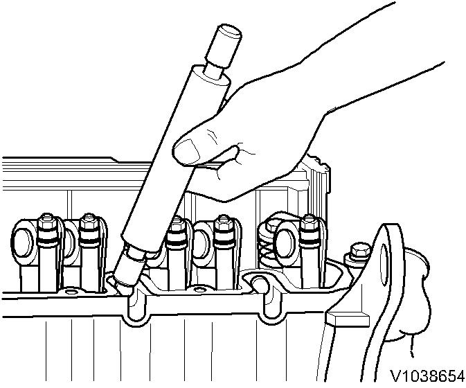
If necessary, screw on adapter 9998007 for the connector.
4. Connect compression tester 9988539. Crank engine with the starter.
5. Carry out compression test on each cylinder.
Compression: 3 +0.8 MPa (30 +8 bar) (435 +116 psi)
NOTE!
The compression measured depends on the starter rpm during the measurement and the engine's altitude. Therefore, exact limit valuescannot be set. Compression measurement is recommended only for comparison of all engine cylinders. If a deviation of more than 15% is found, the cylinder in question should be dismantled to determine the cause.

6. Install compression tester and connector.
7. Install injection valves.
3. Figure 3Document Title: Function Group: Information Type: Date: Cylinder head, description 211 Service Information 2014/3/10
Profile:
CWL, L45B [GB]
Cylinder head, description
The cylinder head is made of cast iron. The inlet air enters vertically (A) and the exhaust gases exit horizontally (B). Inlet and exhaust are on the same side of the cylinder head.

The cylinder head gasket is a multi-layer gasket with 1, 2 or 3 identification holes to indicate the three different thicknesses. The choice of gasket thickness is determined by the piston protrusion over the cylinder head sealing surface. If new pistons or a new cylinder block are fitted, the gasket thickness must be evaluated and changed if necessary.

Document Title: Function Group: Information Type: Date: Valves, description 214 Service Information 2014/3/10
Profile:
CWL, L45B [GB]
Valves, description
The engines are equipped with one inlet and one exhaust valve per cylinder. The upper area of the valve guide (on the valve stem) houses an O-ring (A). This O-ring seal should prevent a large level of oil consumption and reduce the amount of hydrocarbons in the exhaust. Valve rotation is achieved through the eccentric position of the rocker arm. The valve springs have a prescribed direction of installation. The closely wound end of the valve spring must point toward the cylinder head.

Rocker arm lubrication is a component of the centralized lubricating system. The oil is supplied via the tappets and push rods.
Due to a new valve spring guide design, it is no longer possible to use a feeler gauge to adjust the valves of L40B machines from SN 1913001 – / 1923001 – and L45B machines from SN 1943001 – / 1953001 –. For this reason, valve clearance must be adjusted using the rotation angle disc.

Document Title: Function Group: Information Type: Date: Valves, adjusting 214 Service Information 2014/3/10
Profile:
CWL, L45B [GB]CWL, L45B [GB]
Go back to Index Page
Valves, adjusting
Op nbr 214-012
885530 Rotation tool
NOTE!
Only adjust the valve clearance with cold engine.
1. Place the machine in service position.
2. Remove pressure control valve and valve cover.
Valve cover with pressure control valve

3. Remove retainer plate with cabling.
NOTICE
Valve adjustment with the engine running is not allowed since the valves may strike the piston, causing severe damage.
4.
NOTE!
Valve overlap means: exhaust valve not yet closed, inlet valve begins to open.
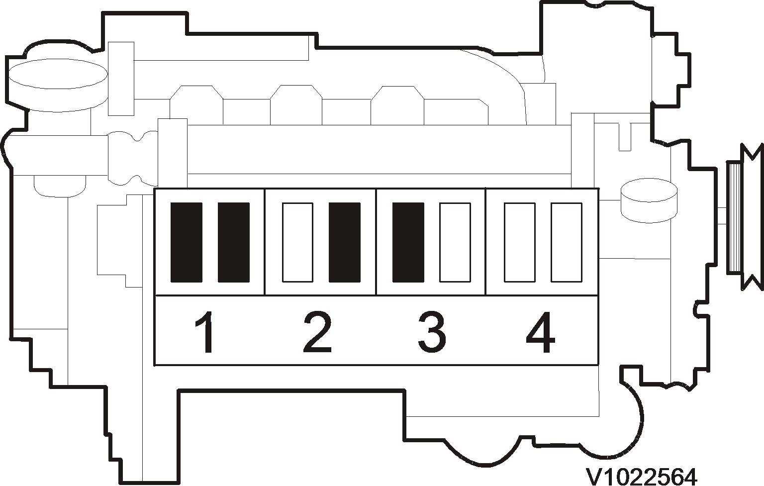
5. Adjust the valves marked black in illustration. Inlet valve: 0.3 mm (0.0118 in)
Exhaust valve: 0.5 mm (0.0197 in)
NOTE!
In case the cylinder head gasket has been replaced, increase valve clearance by 0.1 mm (0.0040 in) !
6. Tighten the lock nut to 20 ±2Nm (15 ±1.5 lbf ft). Check the valve clearance again with the feeler gauge.
7. Rotate the engine again, one full turn until the valves on cylinder 4 are at "valve overlap". Adjust the valve clearance on valves marked black in the illustration.
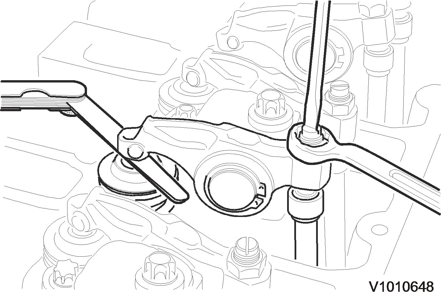 Figure 3
Figure 4
Figure 5
Figure 3
Figure 4
Figure 5
8. Install the gasket, replace if necessary.

9. Attach the valve cover and retainer plate. Tightening torque 11 Nm (8.1 lb ft) NOTE!
Ensure that the rubber seals for the fuel lines are fitted in the correct position during assembly.
10. Attach pressure control valve to valve cover. Tightening torque 8.5Nm (6.3 lb ft)
Figure 6 Figure 7 1. 2. Valve cover gasket Rubber seal Figure 8 Valve cover with pressure control valveDocument Title: Function Group: Information Type: Date: Valves, adjusting 214 Service Information 2014/3/10
Profile:
CWL, L45B [GB]CWL, L45B [GB]
Go back to Index Page
Valves, adjusting
Op nbr 214-012
885530 Rotation tool
885812 Timing tool
NOTE!
Only adjust the valve clearance with cold engine.
1. Place the machine in service position.
2. Unscrew the bolts (1) and remove crankcase ventilation (2).
Crankcase ventilation channel
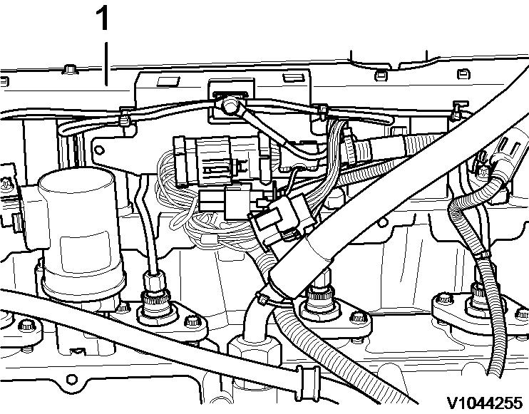
3. Remove the cover plate (1) with wiring.

NOTICE
Valve adjustment with the engine running is not allowed since the valves may strike the piston, causing severe damage.
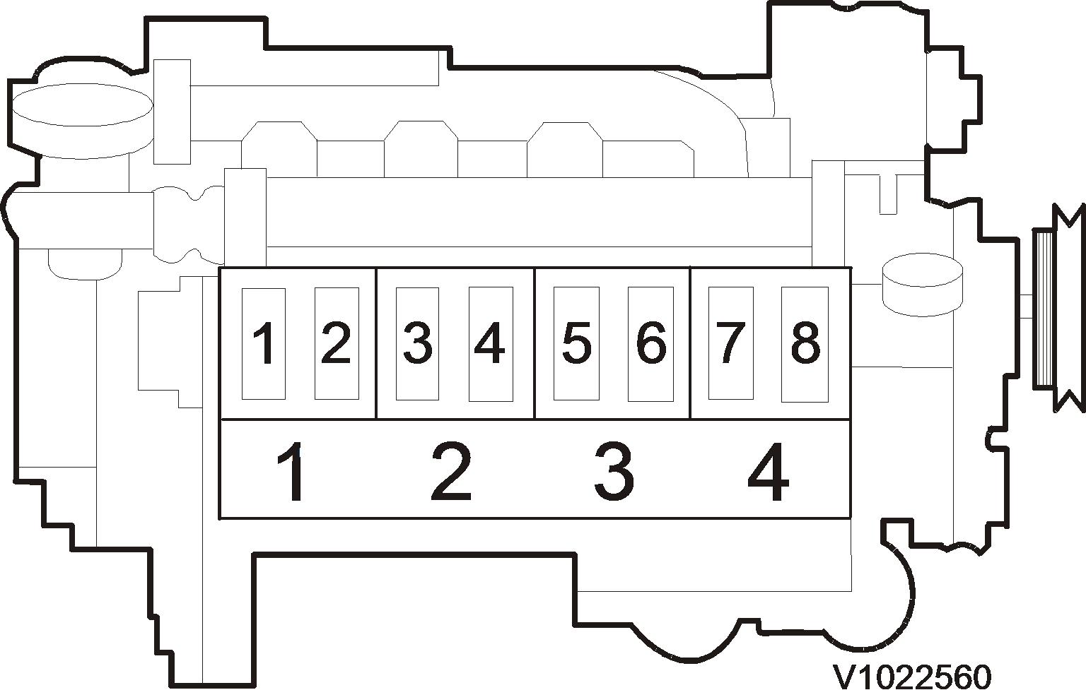
5. Rotate the engine until the valves on cylinder no. 1 stand at "valve overlap".
NOTE!
Valve overlap means: exhaust valve not yet closed, inlet valve begins to open.
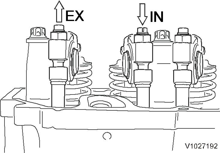
IN = inlet vavle
EX = outlet valve
Adjust valve clearance in accordance with the black mark on the adjustment chart for each cylinder Inlet valve: (IN) 90°
Adjust inlet valve clearance
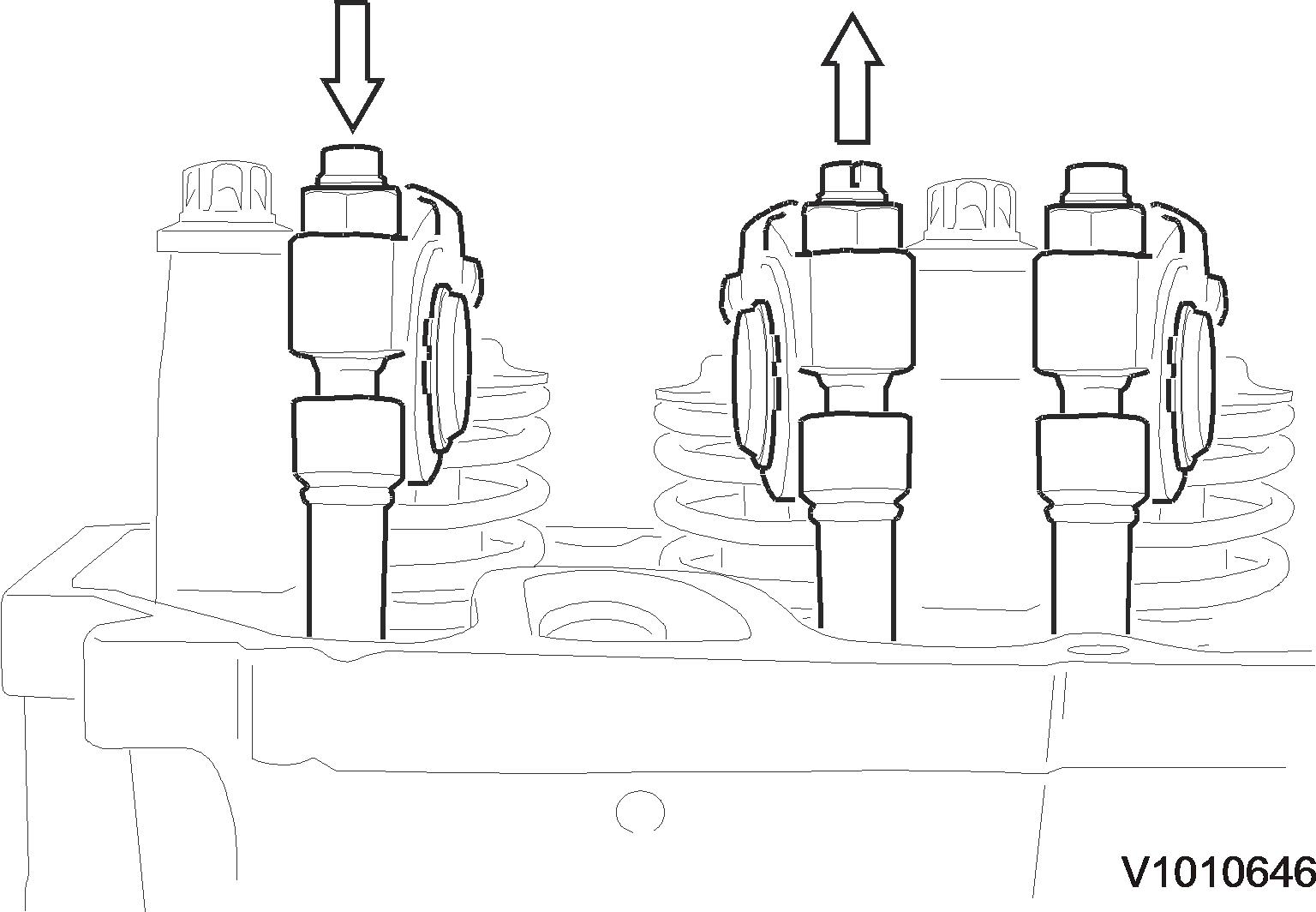
6. Undo the lock nut (1) and screw in the adjustment screw (2) until it makes contact.
Figure 3 1. 2. Exhaust valves: (EX) 1, 3, 5, 7 Inlet valves: (IN) 2, 4, 6, 8 Figure 4 Figure 5NOTE!
The rocker arm must make contact (no gap) with the thrust washer (arrow) of the spring disc.
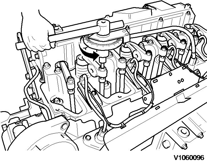


7. Position the rotation angle disc on the adjuster screw. Secure the magnet of the rotation angle disc to the cylinder head. Set the rotation angle disc to "Null" in the direction of the arrow.
NOTE!
Take care not to turn the adjustment screw.
8. Turn the adjustment screw anticlockwise 90°.
Figure 6 Figure 7 Figure 8 9. Counterhold the adjustment screw and tighten the lock nut to 20 ± 2 Nm (14.8 ± 1.5 lbf ft). Remove the rotation angle disc.Suggest:
If the above button click is invalid.
Please download this document first, and then click the above link to download the complete manual.
Thank you so much for reading

Adjust exhaust valve clearance
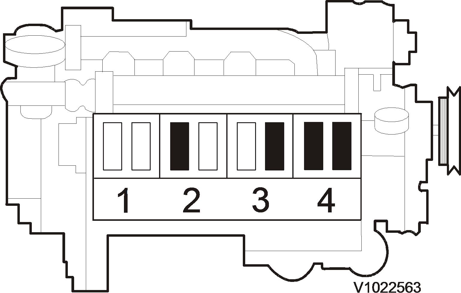
10. Rotate the engine one revolution again until the valves of cylinder no. 4 are at "valve overlap". Adjust valve clearance in accordance with the black mark on the adjustment chart for each cylinder.
Exhaust valve: (EX)150°
NOTE!
Follow steps 6 to 9 for adjusting exhaust valve clearance.
11. Clean the sealing surfaces of the cylinder head.
12. Fit a new gasket to the cylinder head cover.
13. Fit the cylinder head cover and tighten the bolts alternately to 13 Nm (9.6 lbf ft)
14. Fit the cover plate (1) with wiring.
15. Fit the crankcase ventilation. Tighten the bolts to 20 ± 2 Nm (14.8 ± 1.5 lbf ft
16. Start the engine and check for leaks and proper operation.
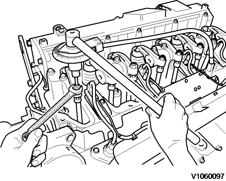 Figure 9
Figure 10
Figure 9
Figure 10