
Shop Manual
K1048003E
Serial Number 5001 and Up
DOOSAN reserves the right to improve our products in a continuing process to provide the best possible product to the market place. These improvements can be implemented at any time with no obligation to change materials on previously sold products. It is recommended that consumers periodically contact their distributors for recent documentation on purchased equipment.
This documentation may include attachments and optional equipment that is not available in your machine's package. Please call your distributor for additional items that you may require.
Illustrations used throughout this manual are used only as a representation of the actual piece of equipment, and may vary from the actual item.
K1048003E Shop Manual
Copyright 2008 DOOSAN
Disassembly Instructions
General Cautions
1.Spread s rubber or vinyl cover on the work bench.
2.When disassembling the traveling motor, provide a match mark on the mating face or each part.
3.Arrange the detached parts to prevent them from being damaged or lost.
4.The disassembled seals must be replaced with new ones as a rule even if they are free from damage.
For disassembly, therefore, prepare new seals in advance.
Disassembly procedure
1.When inspecting or repairing the TM motors, use the disassembling procedures described below.
2.Numerals in brackets ( ) following the part name denote the part numbers used in the operation manual.
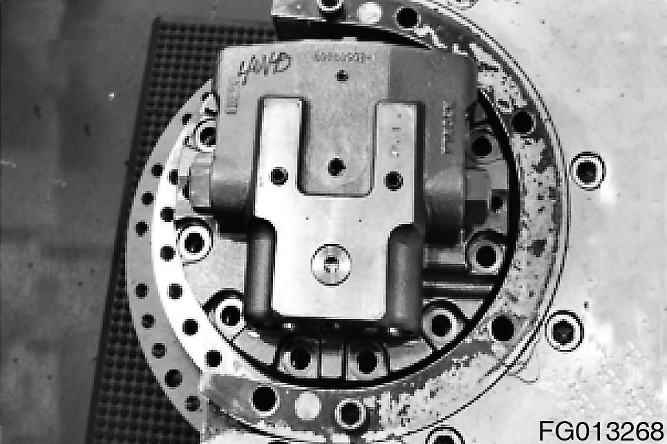
3.Prior to disassembly, install the TM motor on a inversion working bench.
4.Fit the TM motor on the turn-over working die to start its disassembly.
Disassembling the Reduction gear part
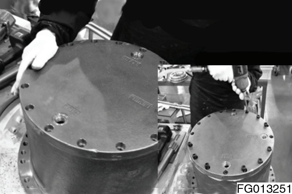
1.Remove plugs (128) (3EA) and drain the reduction gear oil. NOTE: Remove the cover(123), after hook it, fit the eye-bolt in a screw holl for use of the plug(128). If it's impossible, please remove the cover using the rod.
2.Loosen socket bolts (124) (16EA) and remove the cover (123).
NOTE: You can have difficulty removing it because loctite is spread in the socket bolt(124).
•Hexagon wrench 8, 10
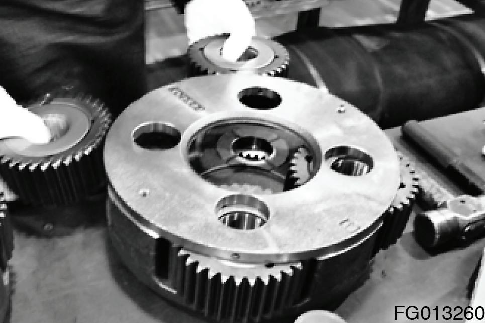
3.Remove drive gear (121).
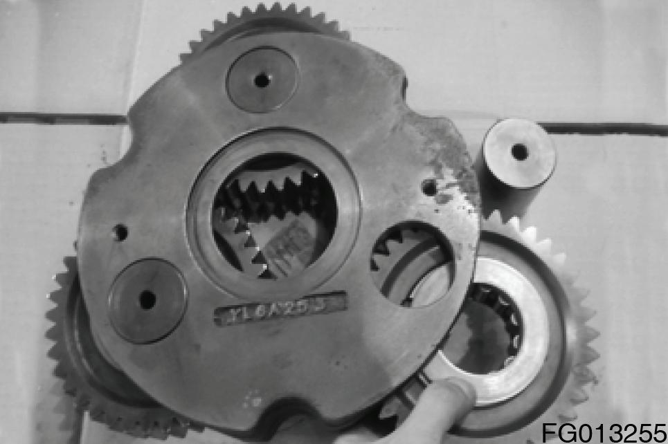
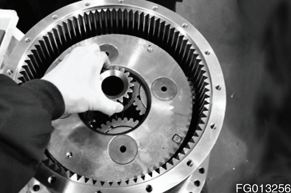
4.Remove carrier no.1 assembly.
NOTE: Carrier no. 1 assembly consists of planetary gear (117), needle bearing (118), shaft bearing (107), carrier (134) thrust washer (131), spring pin (122).
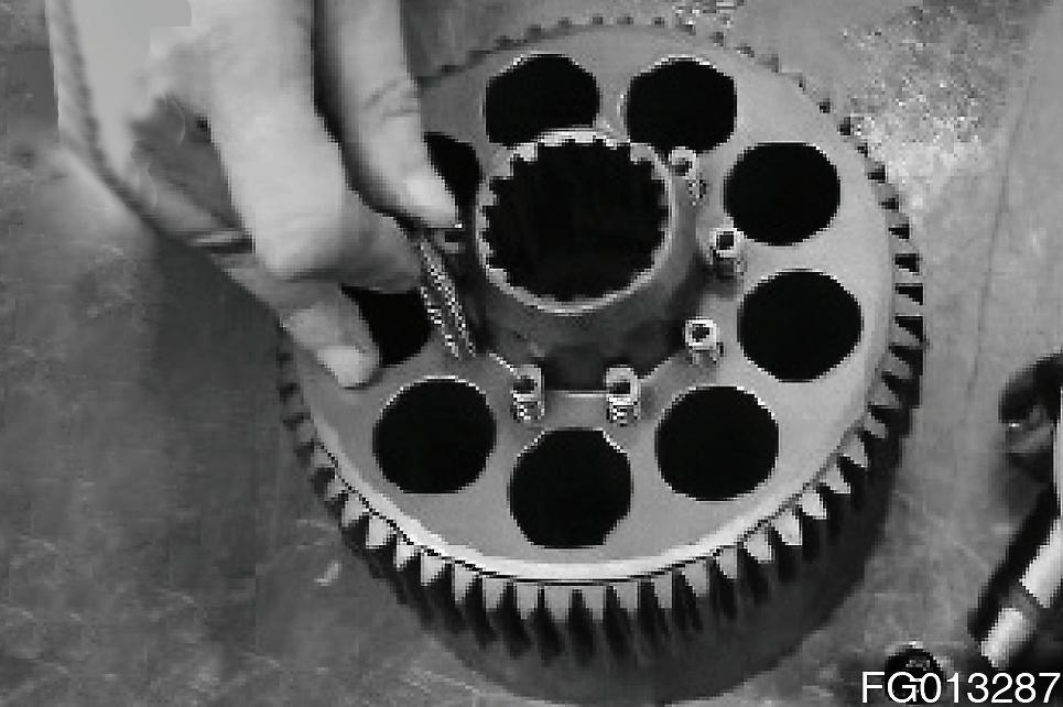
5.Dissembling the carrier no. 1 assembly.
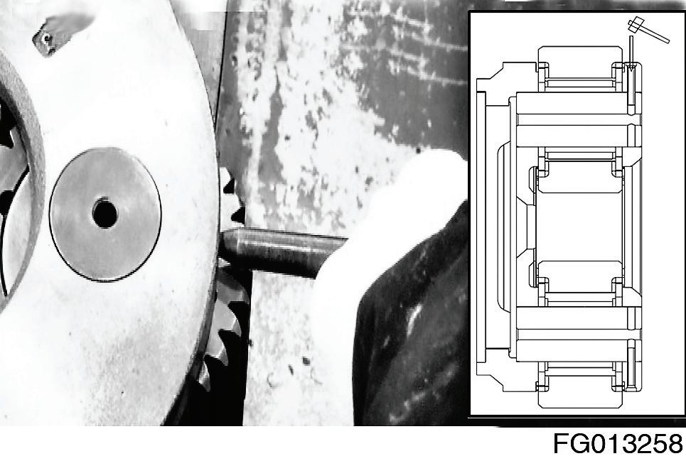
A.Drive spring pins (122) into shaft bearing (R) (107).
NOTE: Please don’t remove if repair is not necessary.
Do not reuse the spring pin (122).
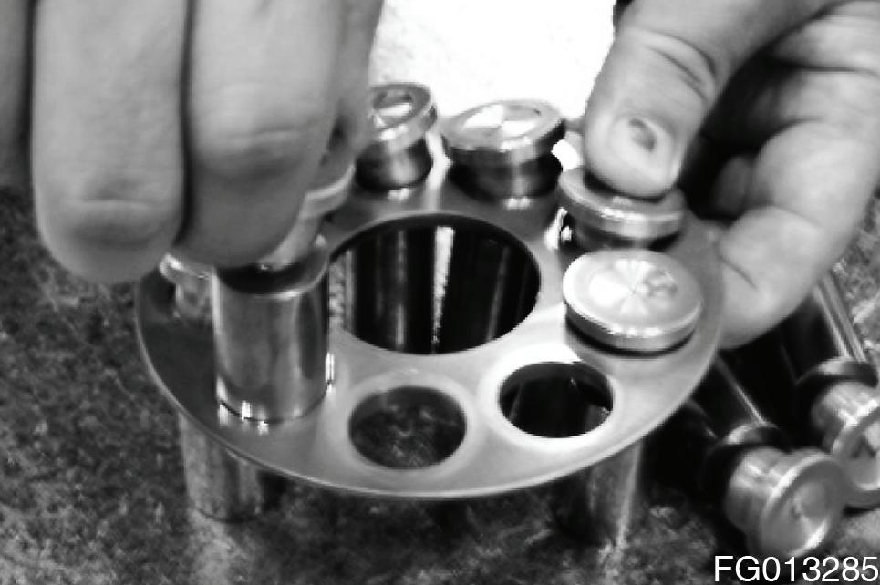
B.Remove shaft bearing (R) (107), planetary gears (R) (117), thrust washer (R) (131), needle bearings (118) and thrust washer (R) (131).
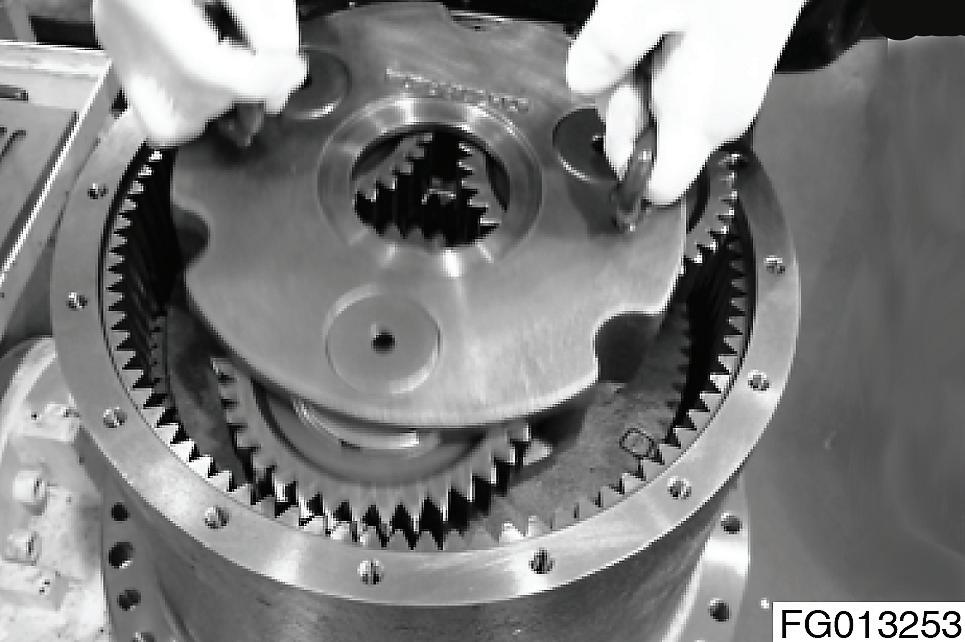
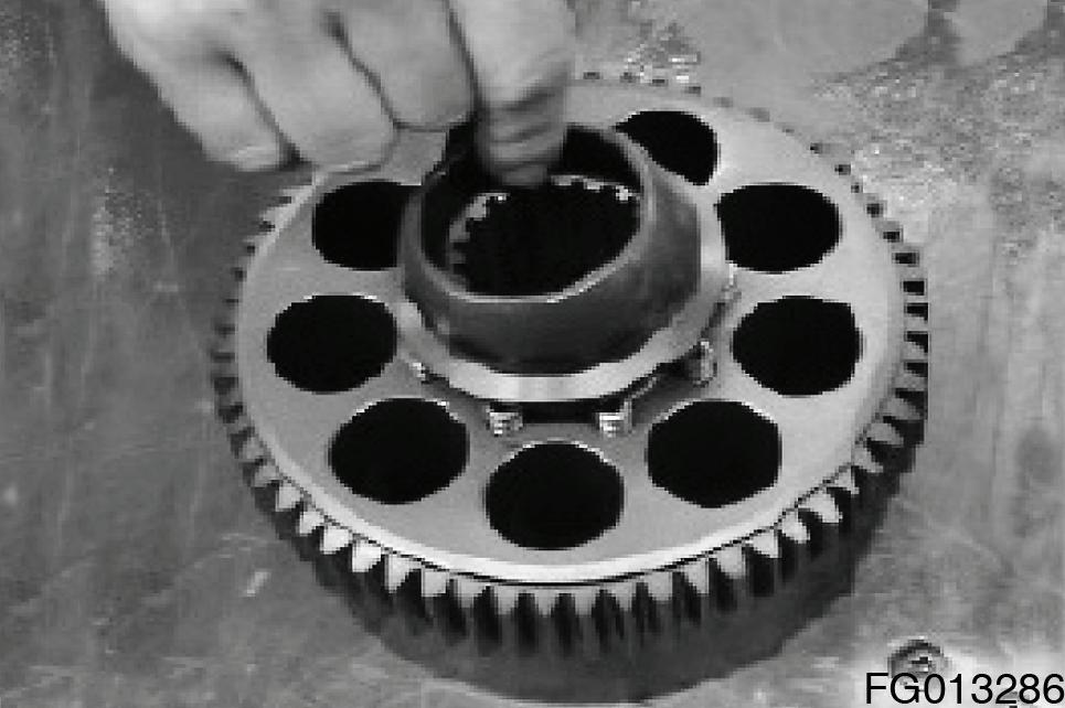
6.Remove sun gear (114).
NOTE: Snap ring (115) is assembled in sun gear (114). Do not remove it if not necessary.
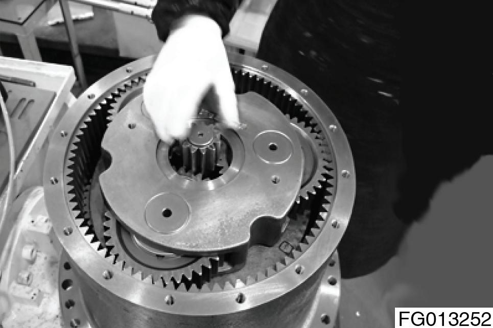
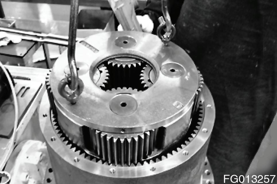
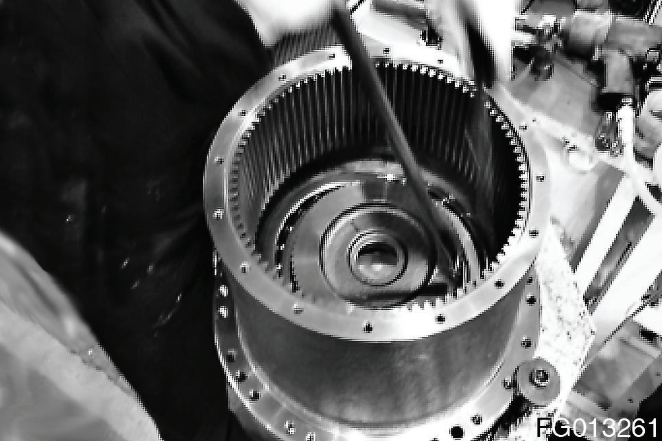
7.Remove carrier no.2 assembly.
NOTE: Remove it using a crane after M10 eye bolt is assembled.
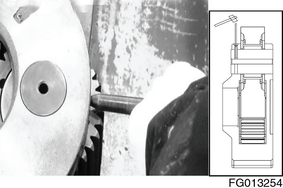
8.Drive spring pins (110) into shaft bearing (F) (113).
NOTE: Do not resue the spring pin (110).
10.Remove the thrust washer (F) (109), planetary gears (F) (108), needle bearings (111), floating bush (112) from carrier no. 2 (103).
NOTE: Each part consists of the 1ST.
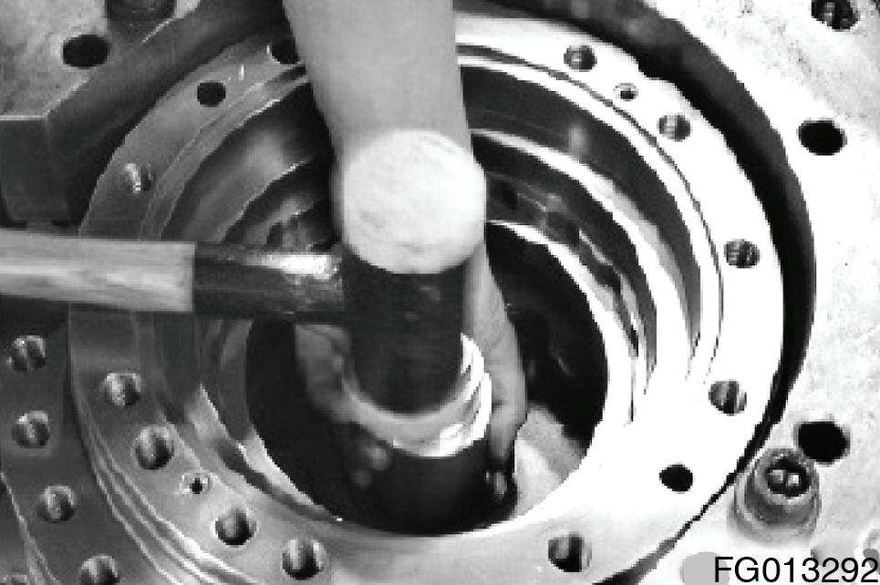
11.Take off lock shim plate (136) by hammering on chisel or on similar tool placed at parting surface.
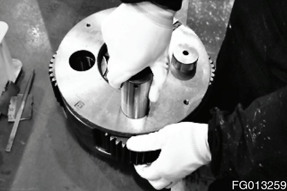
12.Remove the hub[105] from the spindle (101).
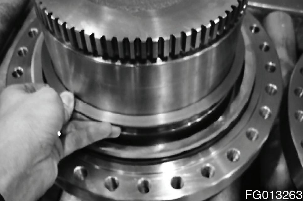
NOTE: Remove it using a crane after M16 eye bolt is assembled at the hub (105).
13.Remove the distance piece[106] from the spindle (101).
14.Remove the floating seal (101) from the hub[105] and the spindle (101).
NOTE: User can remove easily if using ""driver.
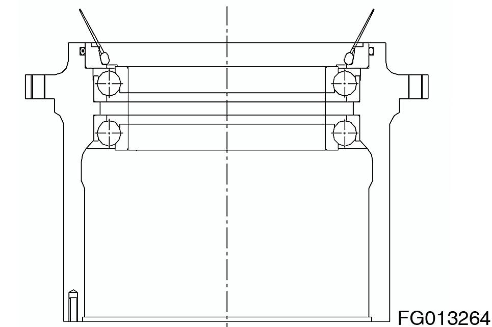
15.The sealing (129), the angular bearing (125) (2EA), the Oring (130) are assembled on the hub (105) with the floating seal (102).
NOTE: Do not remove if not necessary. In case of the removal, be careful not to scratch using aluminum rod or hammer.
Disassembling Hydraulic motor Part
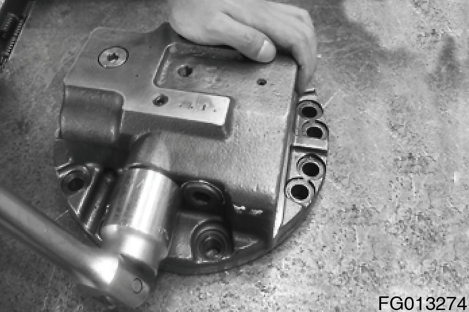
1.Remove the relief valve (2EA) from rear flange (1).
NOTE: Hexagon socket 32/ Torque wrench.
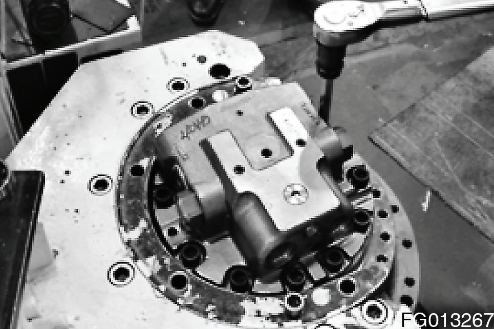
2.Remove hex. socket head bolts (43) from the rear flange (1).
NOTE: Hexagon wrench 14.
3.Remove the rear flange (1) form the spindle (101).
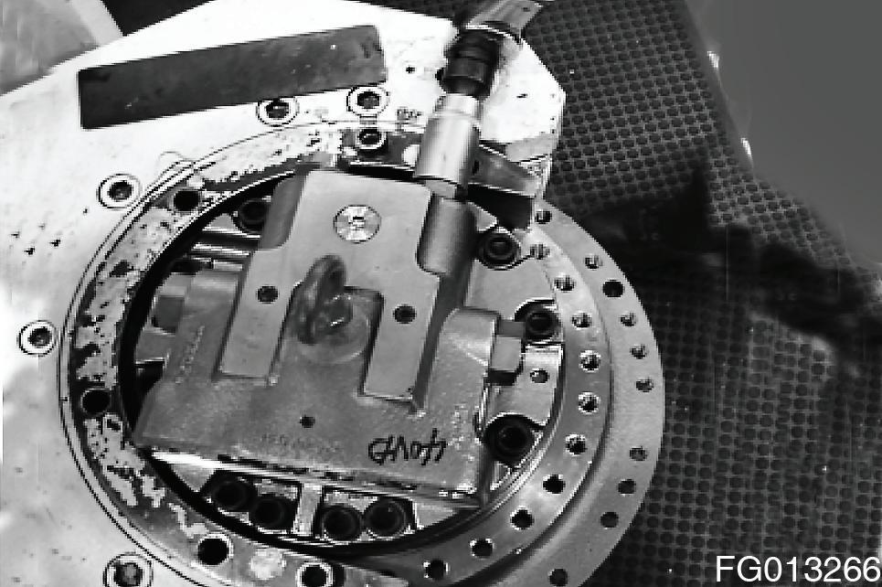
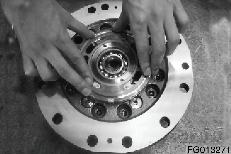
4.Remove the spring (213) (10EA) form the rear flange (1).
NOTE: Remove rear flange (1) carefully after taken using hands. Be carefully not to detach the timimg plate (209) & the spring (213) if twisted or beated by constraint.
5.Remove the paralell pin (42) from the spindle (101).
6.Remove the O-ring (126) from the spindle (101).
Do not reuse the O-ring (126).
NOTE: Do not reuse the O-ring (126).
7.Disassembling the rear flange (1) part
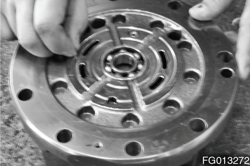
A.Remove the timing plate (9) from the rear flange (1).
NOTE: When removing the timing plate, user can have difficulty of the removal due to the close adhesion of rear flange (1) & oil. Remove it after fitting a rod through the hole which is used when a casting is detached.

Be careful of the leakage due to both surface scratch if using a sharp tool.
B.Remove the paralell pin (41) from the rear flange (1).
C.Remove the ball bearing (250) from the rear flange (1).
8.Disassembling the spool
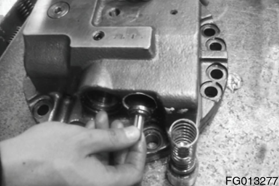
A.Remove two plugs (24) from the rear flange (1).
NOTE: Users can work easily if sub-disassembly was done on the reversal table.
Hexagon socket 41 / Torque wrench.
B.Take out two springs[28], two stopper (c-3) from the rear flange (1).
C.Remove the spool (23) from the rear flange (1).
NOTE: Be careful not to damage the outer surface of the spool (23) and the sliding surface of the rear flange (1).
Since the rear flange (1) and the spool (23) are of the selective fitting type, replace them together as a kit even if only one of the two parts is damaged.
9.Disassembling the check valve
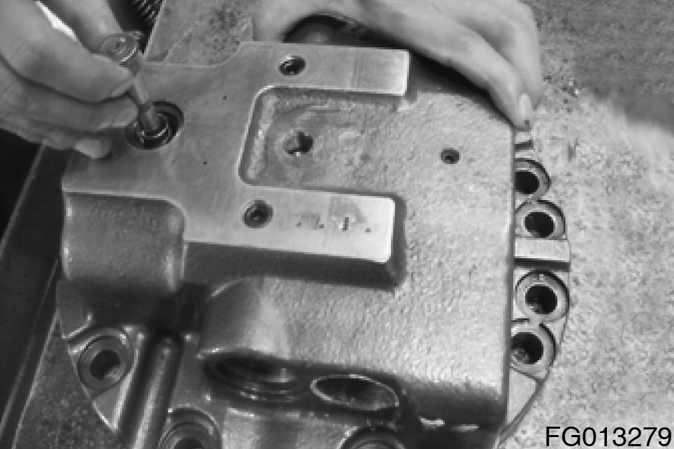
A.Remove two plugs (26) from the rear flange (1)
NOTE: Users can work easily if sub-disassembly was done on the reversal table.
Hexagon wrench 14.
B.Remove the spring (30) (2EA), valve (27) (2EA) from rear flange (1).
10.Disassembling the two speed valve
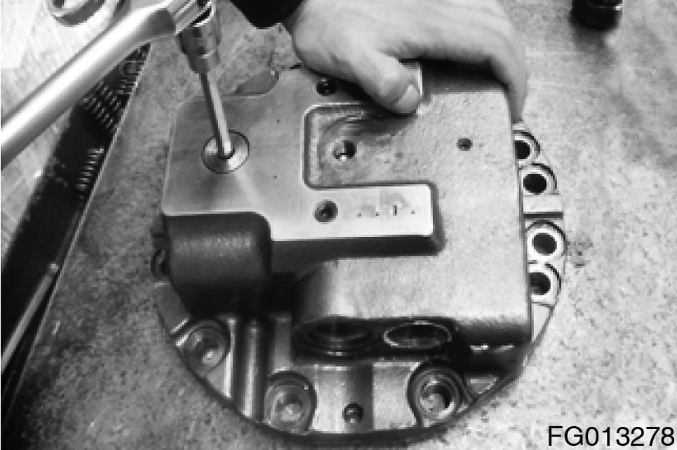
A.Remove the plug (63) from the rear flange (1).
NOTE: Users can work easily if sub-disassembly was done on the reversal table. Hexagon wrench 10.
B.Remove the spool (65), spring (66) from rear flange (1).
11.Disassembling the parking brake
A.Remove the piston (212) by injecting compressed air from the parking brake access hole in the spindle (101).
NOTE: Use the protection cover on the upper part of spindle (101) when users put the pressed air into suddenly.
Otherwise part damage & accident might go on because the piston (212) is rushed out of the spindle (101).
B.Remove the O-rings (235) (239), backup ring (247) (248) from the piston (212).
NOTE: Do not reuse O-rings (235) (239), backup ring (247) (248) after removal.
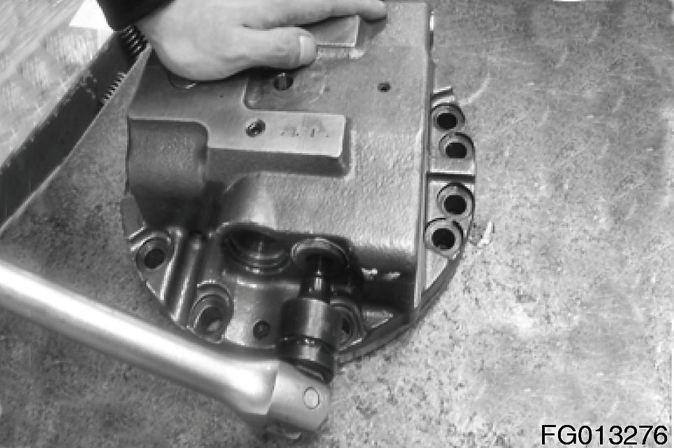
12.Disassembling the Hydraulic motor part
A.Lay the TM motor body on the side.
B.Drain out the oil from the TM motor.
NOTE: Place an oil receptacle under the TM motor to receive the oil flowing out as the motor is being laid on the side.
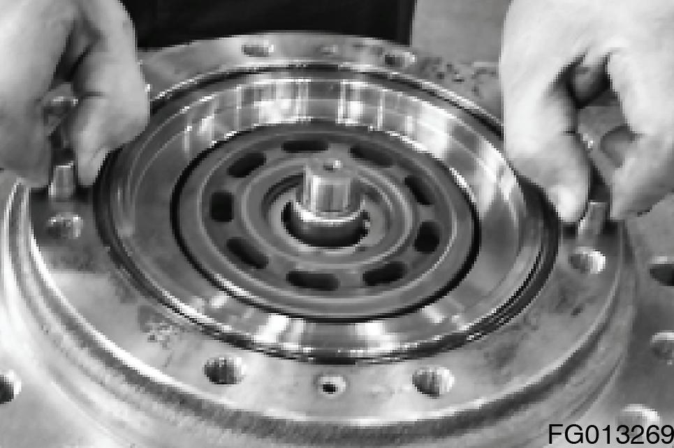
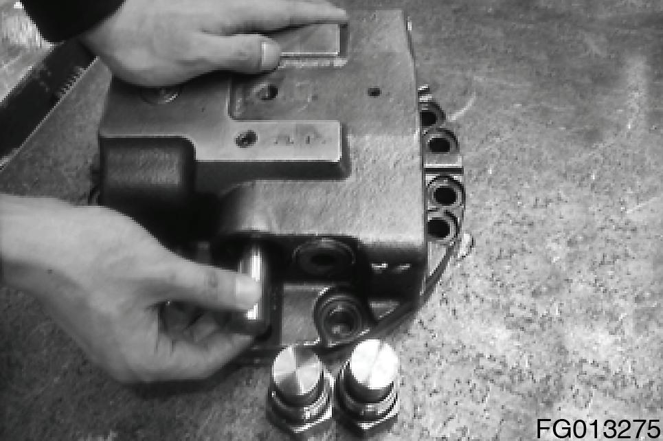
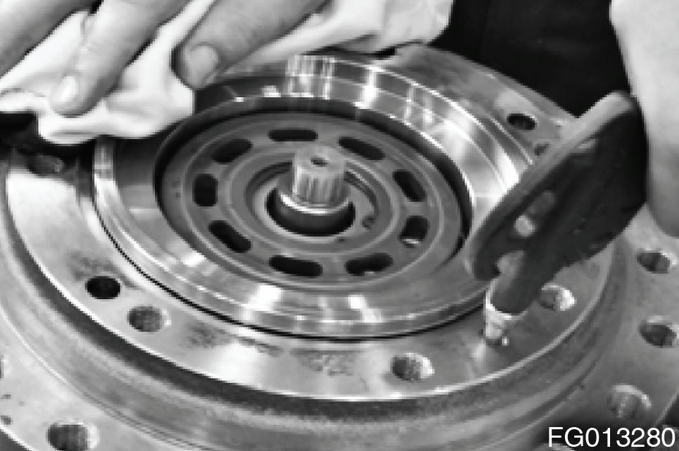
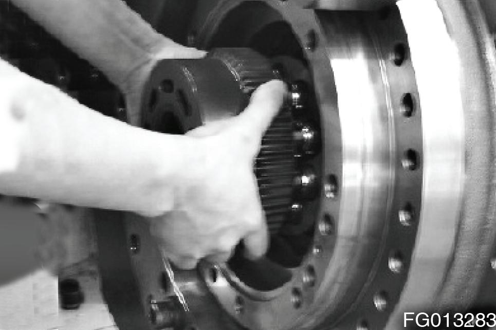
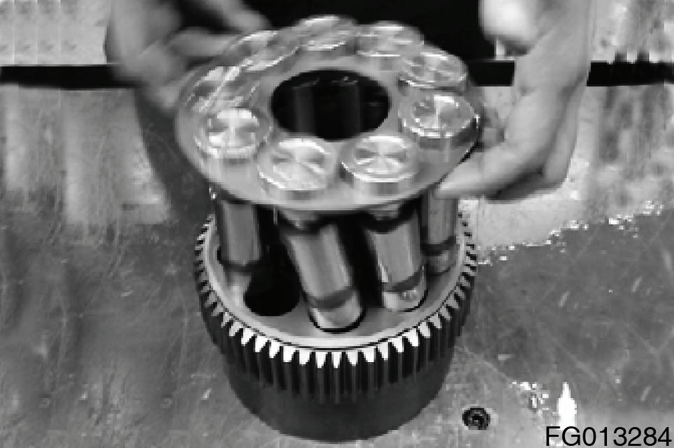
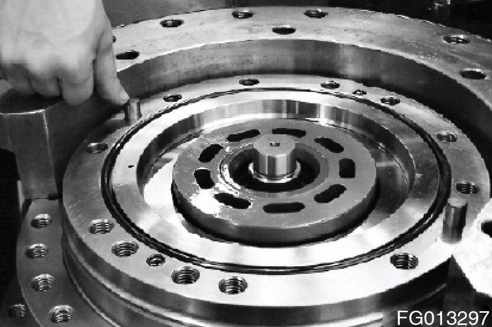
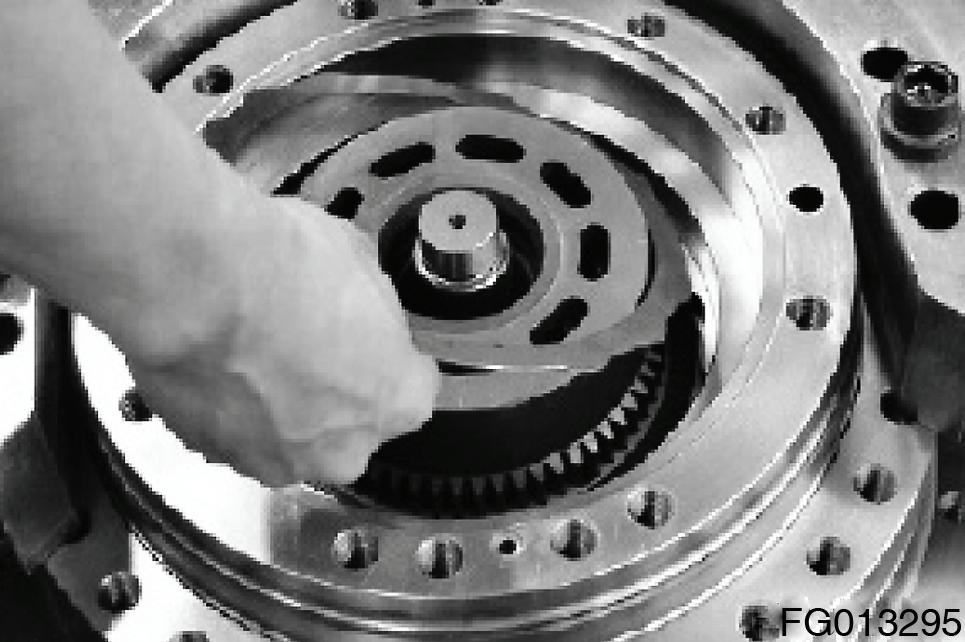
C.Hold the cylinder block (204) with both hands, and remove it from the shaft (202).
NOTE: Before removal, hold the cylinder block (204) with both hands and turn it two to three times in a clockwise and a counterclockwise direction alternately to detach the shoe (206) from the swash plate (203).
D.Remove the mating plates (216) and friction plates (215) from the cylinder block (204).

NOTE: Be careful that if an attempt is made to remove the cylinder block (204) without detaching the shoe (206) from the swash plate (203], then the piston, shoe and other parts that are connected to the cylinder block may come the cylinder loose and fall into the spindle.

13.Disassembling the cylinder block kit
A.Piston assembly (piston (205), shoe (206)) from the removed cylinder block (204).
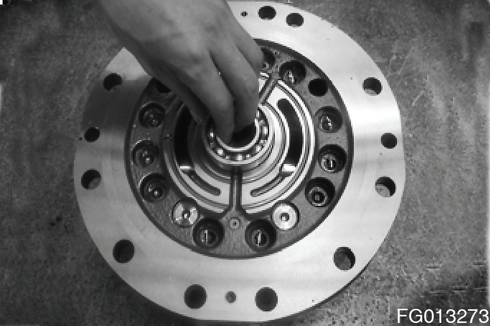
14.Remove swash plate ( 203) from the shaft ( 202).
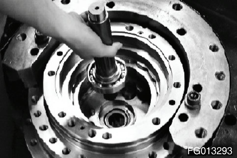
15.Remove shaft (202 ) from the spindle ( 101)
NOTE: When seperating the swash plate, separate and turn it by using hands to free from intervention of the stopper.
16.Remove speed selector piston assembly (piston (261) and shoe (262)) form the spindle (101) by feeding compressed air from the access hole in spindle (101).

NOTE: Piston assembly - Piston (261) Shoe (262)
•Compressed air: 3 ~ 5 kgf/cm2
17. Remove paralell pin (242) pivot (267) from the spindle (101).
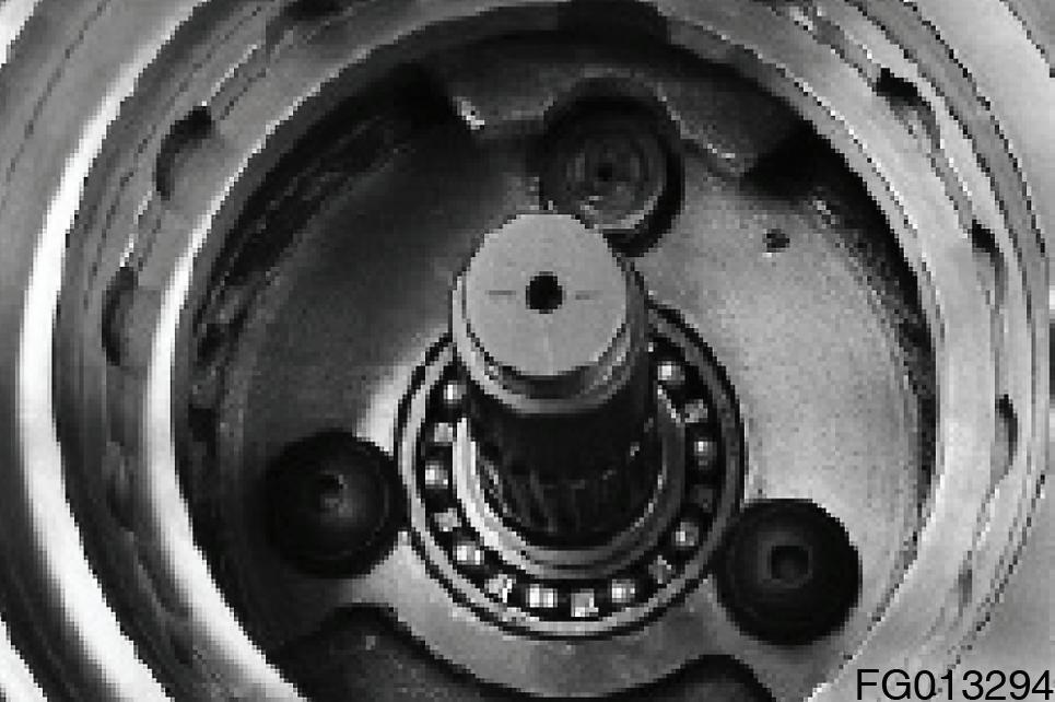
18.Remove ball bearing (249) from the spindle (101)
NOTE: When piston (261) or shoe (262) is damaged, if exchange is necessary, they have to be exchanged together because the seperation is impossible. Use the protection cover on the upper part f spindle when users put the pressed air into suddenly. Otherwise part damage & accident might go on because the piston is rushed out of the spindle.
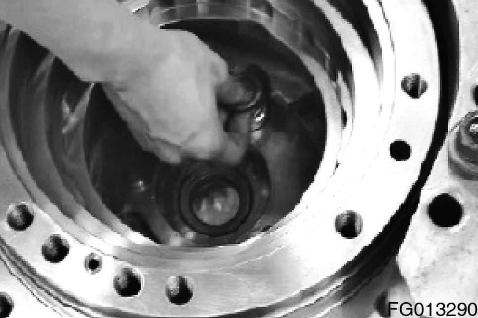
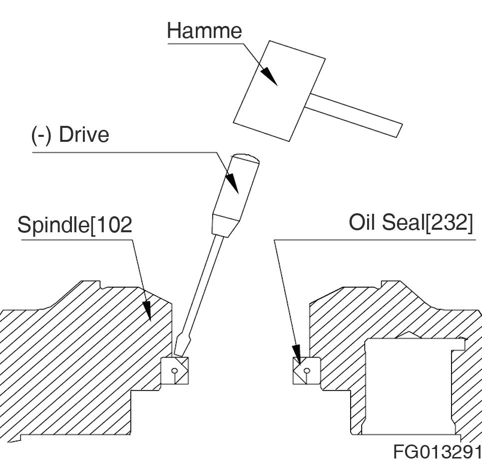
19.Remove oil seal (232) from the spindle (101).
NOTE: Remove the oil seal (232) by hammering at the circumference of the oil seal (232) using driver.
Do not reuse the oil seal (232).
REASSEMBLY
General Precautions
1.Reassemble in a work area that is clean and free from dust and drit.
2.Handle parts with bare hands to keep them free of linty contaminants.
3.Repair or replace the damaged parts. Each parts must be free of burrs its corners.
4.Do not re-use o-ring, oil seal and floating seal that were removed in disassembly.
5.Wash all parts throughly in a suitable solvent. Dry throughly with compressed air. Do not use the cloths.
6.When reassembling oil motor components of TM motor, be sure to coat the sliding parts of the motor and valve with fresh hydraulic oil. (NAS class 9 or above)
7.Use a torque wrench to tighten bolts and plugs, to the torque specified as follows.
Reassembly Procedure
Reassemble the Hydraulic Motor Part
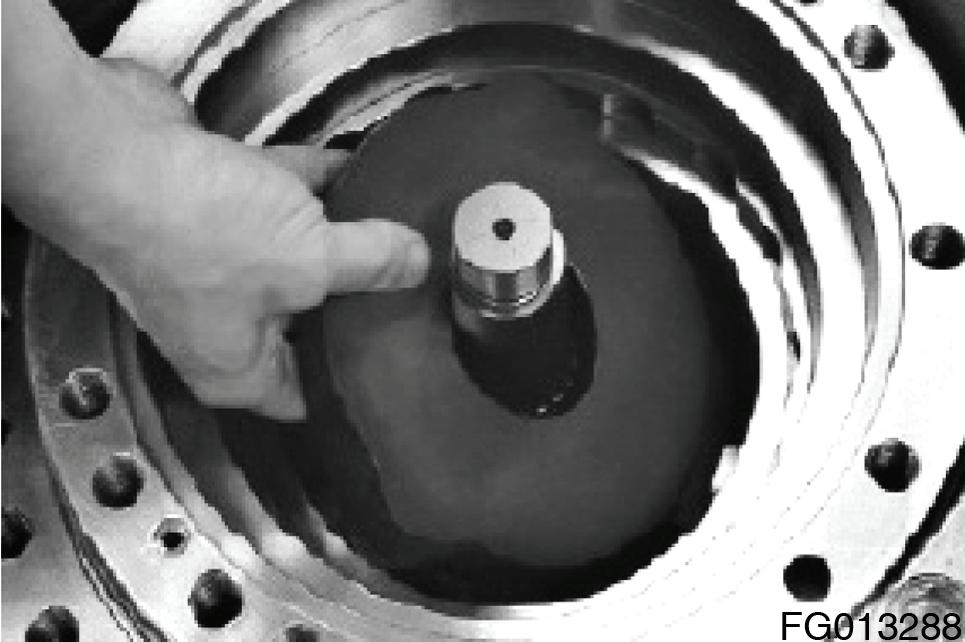
1.Install oil seal (232) into the oil seal hole of spindle (101). NOTE: Apply lithium grease to the lip portion of oil seal (232) position the sqarely over the bore of spindle (101).
2.Install paralell pin (242) (2ea) and two speed piston assembly (261) (262) into the spindle (101).
3.Install shaft (202) into the spindle (101).
NOTE: Assemble after applying grease on oil seal lip (232).
4.Install pivot (267) (2ea) into the spindle (101).
5.Install swash plate(303) to the spindle (101).
NOTE: The swash plate (203) & the 2 speed stopper of the spindle are interferenced. Install the swash plate (203) after rotating. And then install it as the regular position.
6.Reassemble the cylinder block kit
A.Install spring (214) (9ea) to the cylinder block (204).
B.Install thrust ball (208) to the cylinder block (204).
C.Insert piston assembly (piston (205), shoe (206)) into retainer plate (207).
NOTE: After mounting, immerse the entire them in a working fluid.
D.Mount the piston assembly in the cylinder block (204).
7.Install cylinder block (204) assembly to the shaft (202).
NOTE: After fitting splines of both cylinder block (204) and shaft (202), assemble them.
After installing the cylinder (204), confirm whether it revolves or not by turning using both hands.
Motor is malfunction when it isn't revolve.
8.Reassemble the parking brake
A.Install mating plate (216) first and then a friction plate (215), one by one, into the grooves of the outer surface of the cylinder block (204).
NOTE: Immerse the friction plates (215) in a working fluid before fitting them into the grooves.

B.Install O-ring (275) (2ea) into the spindle (101).
C.Install two O-rings (235), (239) and two backup ring (247), (248) in then O-ring grooves of the piston[212]
NOTE: Apply a thin coat of grease to the Orings (235) (239).
D.Mount a piston (212) in the spindle (101)
NOTE: If the piston[212] does not fit into the spindle[101] because of the resistance of the O-ring, tap the edge of the piston[212] lightly and equally with a plastic hammer. Be careful not to damage the O-ring and backup ring at this time.
E.Insert a o-ring (126) into spindle (101).
F.Insert a paralell pin (42) (2ea) into spindle (101).
Reassemble the Rear Flange Part (1)
1.Reassemble the check valve
A.Install O-ring (37) (2ea) on the plug (26) (2ea).
NOTE: Apply grease to the o-ring (37).
B.Install spring (30) and a valve (27) into the plug (26).
NOTE: Install a spring (30) and a valve (27) into the plug (26), and then grease the spring (30) and the valve (30) and hand-lock the former.
C.Install plug (26) into the rear flange (1).
D.Install plug (26) in conjunction with the spring (30) and the valve (30) into the rear flange (1), and tighten the plug to the required torque.
–Tightening torque : 26 ± 4.0 kgf•m
NOTE: Adapter for hexagon wrench 14 /Torque wrench
2.Reassemble the spool
A.Install spool (23) into the rear flange (1).
NOTE: Before installing the spool (23), apply hydraulic oil to the spool. Be careful not to damage the spool's surface & the inner of rear flange (1).
B.Install O-ring (36) on the plug (24).
C.Install spring (28) and a stopper (c-3) into the plug (24).
NOTE: Apply grease to the o-ring (36).
–Tightening torque : 45 ± 9 kgf•m
D.Install plug (24) into the rear flange (1).
NOTE: Exchange it as the rear flange KIT if the exchange is necessary, because the rear flange (301), the spool (323) insist of the rear flange KIT.
–#41 socket/torque for hexagon wrench
Thank you very much for your reading. Please Click Here. Then Get COMPLETE MANUAL.NOWAITING

NOTE:
If there is no response to click on the link above, please download the PDF document first and then clickonit.
E.Tighten the plug (24) to the required torque.
3.Reassemble the two speed valve
A.Install O-rings (46) on plugs (63).
NOTE: Apply grease to the O-ring (46). Apply hydraulic oil to the spool (65), while the spool (65) is installed into the rear flange (1).
B.Insert a spool (65) and spring (66) into the rear flange (1).
NOTE: Be careful not to damage the hole’s inner of the rear flange (1) and the spool (65) outer. It brings on low efficiency of the TMmotor because of the leakage increase after reassembling.
The shaft center should align with the hole center because of little gap.
It is in order to protect the damage and smooth assembling of the rear flange (1) and the spool (65).
C.Insert a plug (63) into the rear flange (1).
–Tightening torque : 10 ± 2 kgf•m
–#10 adaptor/torquer wrench for hexagon wrench
4.Assembling of the rear flange’s inner parts
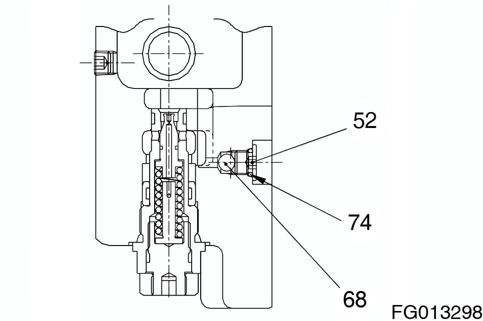
A.After installing the O-ring (74) on the plug (52), install the steel ball (68), the plug (52) into the rear flange (1).
NOTE: Apply grease to the O-ring (74). Do not disassemble & assemble if not necessary.
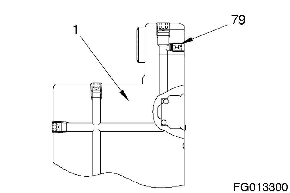
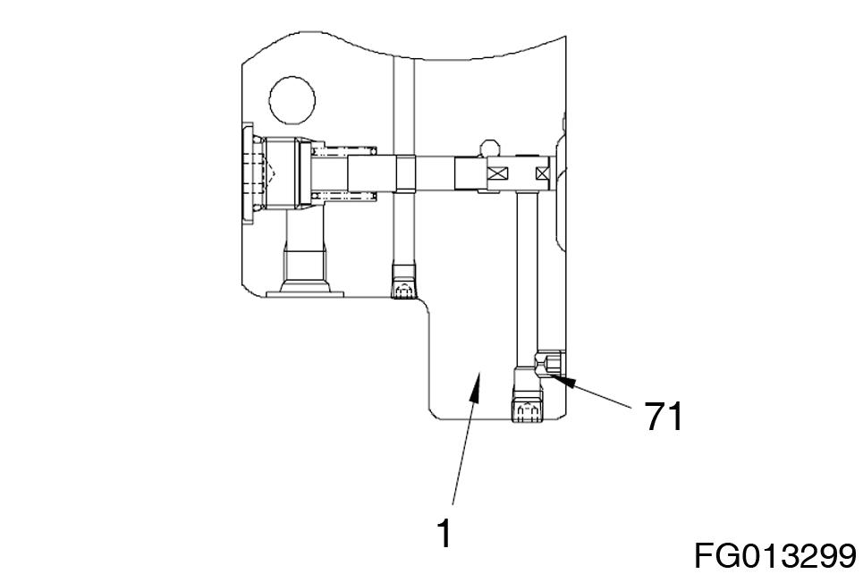
B.Install orifice (71), filter (79) into the rear flange (1). Caulk it after assembling certainly.
NOTE: Do not disassemble & assemble if not necessary.
5.Insert a ball bearing (250), timing plate (209), parallel pin (41) (1ea) and spring (213) (12ea) into the rear flange (1).
NOTE: Be careful not so that the spring (213) & the timing plate (209) should not separate from the rear flange (1).
Apply hydraulic oil to the ball bearing (250).
6.Reassemble the rear flange (1) and spindle (101).
A.Mount the rear flange (1) on the spindle (101).
NOTE: When the rear flange (1) is mounted on the spindle (101), fix the spring (13) applied grease to not drop.
B.Tighten the socket bolt (43) into the spindle (101) to the required torque.
–Tightening torque : 5.9 ± 1.0 kgf•m
–#14 adaptor/torque wrench for wrench
7.Tighten the relief valve into the rear flange[1] to the required torque.
–Tightening torque : 25 ± 5 kgf•m
–#32 socket/torque for wrench