Shop Manual
K1006409E
Serial Number 5001 and Up
Daewoo reserves the right to improve our products in a continuing process to provide the best possible product to the market place. These improvements can be implemented at any time with no obligation to change materials on previously sold products. It is recommended that consumers periodically contact their distributors for recent documentation on purchased equipment.
This documentation may include attachments and optional equipment that is not available in your machine's package. Please call your distributor for additional items that you may require.
Illustrations used throughout this manual are used only as a representation of the actual piece of equipment, and may vary from the actual item.
K1006409E Shop Manual
DX300LC
Table of Contents Page I 1Table Of Contents Safety Track Excavator Safety.........................................................................SP000014 Specifications Specification for DX300LC....................................................................SP000015 General Maintenance General Maintenance Procedures........................................................SP000016 Standard Torques.................................................................................SP000017 Upper Structure Cabin....................................................................................................SP000018 Counterweight.......................................................................................SP000019 Fuel Tank..............................................................................................SP000020 Fuel Transfer Pump..............................................................................SP000021 Swing Bearing.......................................................................................SP000022 Swing Reduction Gear..........................................................................SP000023 Lower Structure and Chassis Track Assembly....................................................................................SP000024 Air Conditioner......................................................................................SP000025 Engine and Drive Train Drive Coupling (Main Pump).................................................................SP000026 Hydraulics Hydraulic System Troubleshooting, Testing and Adjustment...............SP000027 Accumulator..........................................................................................SP000028 Center Joint (Swivel).............................................................................SP000029
Table of Contents Page II Cylinders...............................................................................................SP000030 Swing Motor..........................................................................................SP000031 Travel Motor..........................................................................................SP000032 Gear Pump...........................................................................................SP000033 Main Control Valve...............................................................................SP000034 Hydraulic Schematic (DX300LC)..........................................................SP000037 Axial Piston Pump.................................................................................SP000068 Remote Control Valve (Work Lever / Joystick).....................................SP000069 Travel Control Valve (With Damper).....................................................SP000070 Electrical System Electrical System..................................................................................SP000038 Electrical Schematic (DX300LC)..........................................................SP000039 Attachments Boom and Arm......................................................................................SP000040 Bucket...................................................................................................SP000041
PUMP INPUT POWER CONTROL
Pump Regulator Adjustment
WARNING!
This procedure should be done with two people. To reduce the chance of accident or unintended start-up, one person should remain at the operator's control stand while checks and adjustments are made.
To perform these adjustments accurately the use of a flow meter is strongly recommended, as is consulting the factory (before starting work) to validate the need for making regulator adjustments. Vent hydraulic pressure from the reservoir before breaking the seal on fittings to install the flow meter kit. (Refer to the "Flow meter Installation and Testing" procedure.)
IMPORTANT
Before starting this procedure or going onto make any changes of adjustment settings:
•Verify engine output to the rated speed –2,050 ±50 rpm.
•Permanently mark setscrew positions at the current regulator control setting.
Use a scribe or other permanent marker to identify a reference point on adjusting screws with a corresponding reference on the body of the valve. The adjustment process affects a complex balance and could require some time to complete. If adjustment has to be interrupted or postponed, reference marks at the adjustment point allow immediate restoration of original performance.
This adjustment procedure is normally performed:
• If the engine is being consistently overloaded (and engine troubleshooting shows engine performance to be at or above rated output).
• If reduced cylinder speed and diminished work performance provide an indication that rated, maximum pump flow may not be available (and all other troubleshooting gives no indication of other flaws or hydraulic system defects).
• If pump output is out of balance and one pump is failing to keep up with the output flow of the other.
To check pump imbalance without a flow meter, travel the excavator forward on flat, level terrain. If the machine veers off despite neutral control input and even, balanced track
Hydraulic System Troubleshooting, Testing and Adjustment SP000027
adjustment, the pump which supplies output to the track frame toward which the excavator is veering is weak.
Refer to the illustration of the pump regulator control valve (Figure 12) for the location of adjustment screws (1, 2 and 3). There are two different adjustments, along with the Negacon, negative control, adjustment screw (3, directly below 1 and 2). Each one of the adjustment procedures could affect the setting of the others.
Check and record the arm dump speed performance test before and after input power adjustment, whether or not a flow meter is used.
NOTE: Regulator adjustments affect total cumulative horsepower, since each regulator compensates for
SP000027
Hydraulic System Troubleshooting, Testing and Adjustment
C G D A C E E 2 1 3 F B A G D B F
FG000654
Figure 12
the output of the other. It is not necessary to adjust both regulators at the same time, but after checking or adjusting one of them, the remaining unit should also be checked.
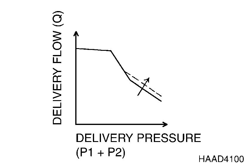
Start the engine and turn the engine speed dial to maximum. When normal operating temperature is reached, loosen the largest diameter lock nut around the adjustment screw (2) for the outer regulator spring. Tightening the screw shifts the P/Q (Pressure/Flow) control curve to the right, and increases compensating control pressure.
On the other hand, if the persistent cause of performance problems is engine overloading, decreasing the adjustment by turning the larger diameter adjusting screw (2) out will decrease pump input horsepower. 1/4 turn on the adjusting screw is equal to approximately 17 horsepower.
IMPORTANT
Because changing the position of adjusting screw (2) also affects the setting of the adjustment for the inner spring, the smaller diameter adjusting screw (1), turn in the inner screw 198° (slightly more than 1/2 turn, 180°) before screw (2) is backed out 1/4 turn (90°).
NOTE: For each full turn of adjustment on the larger diameter screw (2), the square-tipped adjusting screw should be turned in the opposite direction 2.2 turns to avoid changing inner spring adjustment.
Pump input power adjustments are normally made in small increments, 1/4 turn (90°) or less, each time.
Turning the square-tipped, smaller diameter screw (1) clockwise moves the flow curve up, increasing flow and then input horsepower.
The adjusting screw (1, Figure 16) affects the delivery rate (Q) of the pump. Tightening the adjusting screw decreases the maximum cut flow (as shown in Figure 15) while backing out the screw increases cut flow delivery rate.
Balance both pumps for equal output.

Hydraulic System Troubleshooting, Testing and Adjustment SP000027
Figure 13
Q P HDA3008L
Figure 14
Figure 15
A A 1
SP000027 Hydraulic System Troubleshooting, Testing and Adjustment
FG000655
Figure
16
FLOW METER AND FLOW METER KIT INSTALLATION AND TESTING
Checking regulator and pump output, to assess the output balance between the front and rear pumps and to verify operating adjustment of each regulator, will require installation of a flow meter.
The After Sales Service department of the nearest local DOOSAN dealer can assist you with these tests or, if you prefer carrying out your own testing, they should be able to help in putting together a hose and fitting kit (or the required dimensions and specifications for hoses and fittings) to allow you to install a flow meter downstream from the main pump assembly.
Installation and Testing Procedure
• Shut down engine and operate controls to release hydraulic pressure from the accumulator.
•Vent the reservoir to release all pressure from the hydraulic system.
• Remove guard panels from around the main pump assembly.
•Disconnect the main pump discharge output line. Install the input flange of the flow meter on the pump end of the output line.
• Cap off the unused (input) end of the pump discharge line with a blocking flange.
• Connect a premeasured length of hydraulic hose, between the output end of the flow meter assembly and the top of the reservoir. Use appropriate fittings and adapter flanges to guarantee a pressure tight seal.
NOTE: Be sure to maintain even tightening torque on all flange fittings. Use Loctite brand "PST 545" (or an alternate manufacturer's hydraulic system joint seal) if required, to give an airtight seal.
• An assistant – who must remain at the operator's control station at all times – should restart the engine and run it long enough (at minimum rpm) to de-aerate the system and warm up the engine and hydraulic system to operating temperature.
Record the values of all test results in three columns, comparing 1) pump pressure (from the instrument panel display) with 2) measured flow, in gallons or liters per minute, from the installed flow meter. The third column of test results should provide a record of engine rpm measured during each of the following tests – with the engine speed control dial set at maximum, the
Hydraulic System Troubleshooting, Testing and Adjustment
SP000027
power mode selector at Power Mode and the work mode selector at digging mode:
• Unloaded maximum engine speed baseline test (all controls in neutral).
•Front pump test – operate "travel right" lever. Record values at all specified pressures.
• Rear pump test – operate "travel left" lever. Record values at all specified pressures.
Record the values for each of the three tests (neutral, travel right and travel left) at the following pump pressure levels, with travel speed control set at "high speed."
Compare recorded values with output shown in the P-Q curve in the specifications section of this book.
If test results do not measure up to specified values, pump output tests can be repeated using different control levers. Recheck front pump operation while stroking the bucket cylinder out lever, and the rear pump by actuating the swing control lever. NOTE: When testing bucket and swing functions, read maximum flow tests at 330 kg/cm2 (4,785 psi), not 350 kg/cm2 (5075 psi).
SP000027 Hydraulic System Troubleshooting, Testing and Adjustment
Engine RPMPressureFlow
kg/cm2 (1,422 psi)
kg/cm2 (1,930 psi)
kg/cm2 (2,560 psi)
kg/cm2 (3,413 psi) 320 kg/cm2 (4,550 psi)*
below note.
100
135
180
240
*See
SWING SYSTEM TROUBLESHOOTING
Precautions/Initial Checks
1.Stop work. Release all weight or any type of load safely before proceeding. Avoid risking injury or adding to damage.
2.Shut down engine and disengage control functions until initial tests are ready to be made.
WARNING
Prevent possible injury and/or loss of operating control. Stop work and park the excavator at the first indication of:
1.Equipment breakdown.
2.Inadequate control response.
3.Erratic performance.
Stop the machine, put the boom and arm in the inoperative (overnight park) position and begin by making the fastest, simplest checks first:
• Check oil level.
• Check for overheating, oil leaks, external oil cooler clogging or broken fan belt. Consult service record for prior repair/service work.
•Drain some tank oil into a clean, clear container. Look for metal shavings/grit, cloudiness/water or foam/air bubbles in the oil.
NOTE: Dispose of drained fluids according to local regulations.
• Check for wobble through the engine/pump flex coupling. Run engine with the pump input hydraulic power control nut turned to the lowest power to check the engine.
•Investigate unusual operating noises or vibration. Check for loose bolts, connections.
Swing Relief Valve Checking and Adjustment
Make a check of operating pressures through the swing relief valve if:
• The swing motor fails to turn.
• Swings in one direction only.
Hydraulic System Troubleshooting, Testing and Adjustment SP000027
• Swings but continues to coast.
• There is drifting on a slope.
1.Check operation by connecting:
A.Two 600 bar (8,700 psi) pressure gauges to the inlet and outlet measuring ports on top of the swing motor.
Pressure should be between 270 and 280 bar (3,916 psi and 4,060 psi), with both swing locks engaged. With swing locks released, during full acceleration and deceleration, pressure should approach 250 bar (3,625 psi) in each direction.
B. Connect a 60 bar (870 psi) pressure gauge at the "SH" port of the hydraulic brake.
Pressure should always stay at or above 13 bar (190 psi) when operating swing, boom or arm.
C. Connect a 10 bar (145 psi) gauge at the motor makeup valve.
Pressure should stay consistently above 2.5 bar (36 psi). If pressure falls below the recommended minimum level, forceful acceleration of the swing motor could lead to cavitation of the circuit and stalling, slowed rotation, noise and possible damage.
2.If main inlet and outlet pressures were off in the preceding tests in Step 1, adjust swing relief valve pressure.
Following adjustment, repeat the operating pressure tests (with gauges connected to the inlet and outlet test ports on top of the swing motor) and check pressures with the swing locks engaged and released.
If pressure adjustment fails to restore adequate performance, proceed to the Troubleshooting – Swing table.
3.If pressure tests were at recommended levels through the main inlet and outlet ports, and through the "SH" port of the swing brake, the causes of poor swing performance could include a faulty swing motor, drive train overloading or gearbox defect, or a problem in the brake assembly or swing control valve. Proceed to the troubleshooting information in the next procedure.
If pressure through the "SH" port was tested below the minimum 13 bar (190 psi) level, check the shuttle valve in the rear compartment behind cabin. When pressure through the port is at the recommended level, the brake release valve should disengage the swing brake, allowing the swing motor to rotate the excavator. If pressure adjustment to the valve has been restored but the brake still fails to release, the brake piston or friction plate may be frozen, requiring disassembly of the motor and parts repair/replacement.
4.If pressure tested at the motor makeup valve falls below recommended minimum level, and consequent problems
Hydraulic
SP000027
System Troubleshooting, Testing and Adjustment
with cavitation, stalling and surging are observed, check the restriction valve. If pressure adjustment to the valve has been restored but if problems with cavitation continues, disassemble the upper swing motor housing and clean or replace assembly components as required.
NOTE:If all tested pressures are at or above recommended levels, and there are no mechanical problems in the drive train or in the motor/brake assembly, the problem will require further hydraulic troubleshooting. It's also possible that a defective joystick, an intermittent short in an electrical control circuit or a problem in the e-EPOS circuit is causing diminished swing performance. Pull out the e-EPOS indicator panel from underneath the operator's seat and perform the self-diagnostic test. If the display panel reads code "0.2," it is reporting that the swing priority proportional valve is not functioning, except in the minimum "fail-safe" mode. Refer to the Electrical section of this book for more information.
and
SP000027
Hydraulic System Troubleshooting, Testing
Adjustment
DISASSEMBLY
CAUTION!
Vent air from the hydraulic system before disconnecting cylinder piping connections. Use the lever on the reservoir, while the engine is running. Discharge the hydraulic accumulator and vent residual tank pressure after the engine is shut off. Pour clean replacement fluid back into the system if excessive fluid is lost.
1.Following removal of cylinder from excavator attachment, support cylinder on some type of sturdy work platform and drain all oil. Rotate cylinder so that piping ports are on top, to allow trapped air to vent.
2.Position piston rod so that it is extended approximately one half meter (20").


3.Remove bolts (7) on the end of cylinder.
NOTE: Wrap a cloth or other protective material around piston rod, to avoid possibility of accidentally scratching or scoring rod surface while fasteners are being loosened and removed. Component parts (numbered in parentheses) are keyed to Figure 4.
SP000030 Cylinders Page 18
Figure 12
Figure 13
Figure 14
4.Tap two bolts into cover of cylinder head, 180° apart. Tighten them in a staggered, even sequence, to back off piston rod end cover from edge of cylinder wall. Look for adequate clearance between cover and end of cylinder wall before using a plastic or other soft-faced hammer for final disassembly.

5.Begin withdrawing piston rod assembly, away from cylinder. Attach a lifting support when final 1/3 of rod is still inside barrel of cylinder. Prepare support blocks for piston rod before it has been completely withdrawn.
6.Lower piston rod to support blocks and detach wear ring (outer surface) (18) from end of rod.
7.Immobilize piston rod by inserting a wooden or other nonscoring, nonmetallic support through end of rod.


Cylinders Page 19
SP000030
Figure 15
Figure 16
Figure 17
Figure 18
8.Remove set screw using socket wrench.
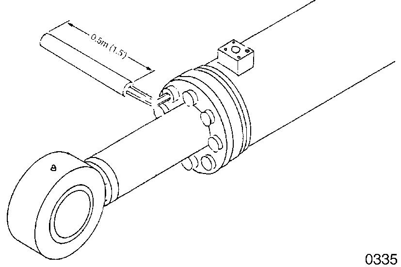
9.Fabricate or purchase a piston nut removal wrench. (Dimensions are called off at beginning of this procedure. This tool may also be ordered through your local DOOSAN Parts distributor). Remove nut from end of piston.
10.Use second piston tool described at beginning of this procedure to separate piston. Detach cushion ring (15), taking care not to damage cushion ring.


11.Use a plastic hammer to evenly pull off rod cover (9) from end of piston rod. Be careful not to damage rod bushing (6) and dust wiper, U-packing and other seals.

Page
SP000030 Cylinders
20
HAOF340L
Figure 19
Figure 20
Figure 21
Figure 22
12.Use a dull, rounded tip tool to pry off O-ring (11) and backup ring (12).
13.Find a screwdriver with an appropriate width tip to facilitate removal of slipper seal (19), wear ring (18) and slide ring (17) from piston (16).

14.Remove O-ring (20) and backup ring (21) from cylinder head.
15.During disassembly of cylinder head, be careful not to damage buffer seal (5) and U-packing (4).
Cylinders Page 21
SP000030
HAOF37OL
Figure 23
Figure 24
HAOF38OS
Figure 25
HAOF39OL
Figure 26
16.Disassemble retaining ring (3) and dust wiper (2). Separate retaining ring (8) and rod bushing (6).

17.Force out pin bushing (1) from body of cylinder.

SP000030 Cylinders Page 22
Figure 27
Figure 28
Thank you very much for your reading. Please Click Here. Then Get COMPLETE MANUAL.NOWAITING

NOTE:
If there is no response to click on the link above, please download the PDF document first and then clickonit.
REASSEMBLY
IMPORTANT
Replace any part that shows evidence of damage or excessive wear. Replacement of all O-rings and flexible seals is strongly recommended. Before starting the cylinder reassembly procedure, all parts should be thoroughly cleaned and dried, and/or prelubricated with clean hydraulic fluid. Prepare the work area beforehand to maintain cleanliness during the reassembly procedure.
NOTE: Reassemble the subassemblies of the cylinder in the following order:
1.Body of the cylinder.

2.Piston rod.
3.Piston assembly.
4.Cylinder head assembly.
1.Reassemble pin bushing (1) to piston rod (13) and body of cylinder (14).
2.Following reassembly of rod cover components, install the dust wiper (2) and rod bushing (6) to the rod cover (9). Insert retaining rings (3 and 8).
Cylinders Page 23 SP000030
Figure 29
Figure 30
3.Prelubricate O-rings and seals before reassembly (Figure 31).


4.Before starting to rebuild piston assembly, heat slipper seal for 5 minutes in an oil bath warmed to 150° - 180°C (302°356°F). Use special slipper seal jig (third item in list of specialized tools at the beginning of this procedure) to attach seal. Cool seal by pushing a retracting jig against seal for several minutes. Apply a strip of clean, see-through sealing tape around slipper seal to keep it free of dust.
5.Immobilize piston rod on solid support blocks. Assemble Oring (20) and backup ring (21). Prepare to attach rod cover assembly to piston rod. Push rod cover by tightening piston nut (22).
6.Assemble cushion ring (15) and attach piston assembly to piston rod.
SP000030 Cylinders Page 24
Figure 31
Figure 32
Figure 33
Figure 34
7.Use specially fabricate or factory sourced tool to tighten piston nut (22).
8.Assemble wear ring (18), slide ring (17) and set screw (23) to piston assembly.
Reference Number Description
1
Set Screw

9.Immobilize body of cylinder before reassembly.


Preapply fastener locking compound (Loctite #242 or #243 or an alternate manufacturer's equivalent product) to all end cover retaining bolts. Wrap a protective cushion around end of rod while tightening fasteners, to prevent possible damage to polished surface of rod, should a wrench slip during retightening.
SP000030

Page 25
Cylinders
Figure 35
Figure 36
Figure 37
Figure 38

