Service Training BW 100 AD/AC Series 4 BW 120 AD/AC Series 4 P/N 008 099 86STATUS: 03/2004
BW 100/120 AD-3 1 BW 100/120 AC-3 Table of contents Foreword A 1 List of additional documentation A 2 General A 3 Maintenance A 4 List of components B 1 Kubota diesel engine C 1 View of engine C 2 Pump installation on diesel engine C 3 View of diesel engine, flywheel side C 4 Tests and adjustments C 5 Adjusting the valve clearance C 6 Trouble Shooting C 8 Travel system D 1 Travel pump D 3 Travel pump control D 7 Charge pressure relief valve D 9 High pressure relief valvesD 10 Drum drive motorD 12 Wheel drive motors on AC-machinesD 16 Trouble shooting travel systemD 17 Insufficient travel powerD 28 The machine moves with the travel lever in “Neutral”D 30 Vibration E 1 Vibration pump E 3 Vibration control valve E 4 Vibration motor E 5 Trouble shooting vibration E 6 Steering F 1 Steering valve F 3 Trouble shooting steering F 5 Electric circuit diagrams G 1 Table of contents G 1 Function groups G 2 Reference lines, frames G 3 Potential cross references G 4 Relay cross references G 5 List of components G 5 Electric system G 6
Service Training
Service Training
Foreword
In 2004 the tandem vibratory rollers of product range BW 100 AD/AC4 and BW 120 AD/AC4 were launched in the market for the first time. They are a further development of the old BW 100/120AD/AC of generation 3, which already were a great sales success.
The contents of this training shall enable the service engineer to perform adjustments and trouble shooting as well as all necessary repair work in a professional manner. The owner of the machine should recognize that the service engineer is fully familiar with the machine. He should realize that the service engineer applies the correct measures to detect a possible fault on a machine and that all repair measures are performed with skill and knowledge. Persons participating on this training course should be confident when having to work on this machine.
Documentation
For the BOMAG machines described in this training manual the following documentation is additionally available:
Attention!
The currently valid part numbers for the documents can be taken from the Doclist or the Customer Service page in the BOMAG Intranet or Extranet (BOMAG Secured Area) in accordance with the serial number of the machine.
1. Operating and maintenance instructions
2. Spare parts catalogue
3. Wiring diagram*
4. Hydraulic diagram*
5. Repair instructions
6. Service Information
* The document versions valid at the date of printing are part of this training manual.
BW 100/120 AD-4
BW 100/120 AC-4
A 1
Service Training
General
Machines of product range BW 100/120 AD/AC-4 are tandem vibratory rollers or combination rollers for compaction work in road construction. They are most suitable for the compaction of bituminous materials as well as light compaction tasks in earthwork. Compaction is achieved by the vibration of both drums or the vibration of the drum and the static load of the rubber tires. The power output from the water cooled Kubota diesel engine is transferred to drums or wheels (travel and vibration systems) and to the steering via the hydrostatic drive systems of the machine. This type of power transmission ensures lowest possible efficiency losses.
Both drums of the BW 100/120 AD-4 are fitted with both travel motors as well as vibration motors. The motors for the respective drive systems are always arranged on one side of the machine. Since it is beneficial for many applications (e.g. when laying asphalt layers) to work with one vibrating and one static drum, the machine is equipped with a vibration shut-off valve for the rear drum.
On machines of type BW 100/120 AC-4 the wheel set is driven by two travel motors. This roller combines the high compaction power of a vibration drum with the excellent surface sealing effect of rubber tires in one machine. This machine obviously achieves considerable savings in costs when compared with a pure vibratory or pneumatic tired roller.
The standard equipment of the machine includes a gravity sprinkler system. A pressure sprinkler system is optionally available on request. In connection with the scrapers the water sprinkler system avoids picking up of material by the drums.
On the AC-machines a pressure sprinkler system prevents sticking of dirt and bitumen to the rubber tires. For this purpose the tires are sprayed with emulsion.
Front and rear frames of the machine are joined by an oscillating articulated joint. The amply dimensioned oscillation angle makes sure that the drums always have ground contact over the entire width.
Both travel motors are fitted with integrated brakes working as parking brakes. Depending on the position of the brake solenoid valve these brakes are released by charge pressure when starting the engine and applied when shutting the engine down.
BW 100/120 AD-4
BW 100/120 AC-4
A 2
Service Training
Maintenance
The tandem/combination rollers of series BW 100/120 AD/AC-4 are high performance machines for the extremely difficult use in asphalt compaction and earth work. To be able to meet these demands the machine must always be ready to be loaded up to its limits. Apart from that, all safety installations must always be fully functional when working under the partly very dangerous conditions on a construction site.
Thorough maintenance of the machine is therefore mandatory. This not only guarantees a remarkably higher functional safety, but also prolongs the lifetime of the machine and of important components.
The time required for thorough maintenance is only minor when being compared with the malfunctions and faults that may occur if these instructions are not observed.
The maintenance intervals are given in operating hours. It is quite obvious that with each maintenance interval all the work for shorter preceding intervals must also be performed. During the 2000 hour interval you must also perform the maintenance work for the 500 and 1000 hour intervals.
It should also be clear, that with the 2500 hours interval only the work for the 10 and 500 hour intervals must be performed.
For maintenance work you must only use the fuels and lubricants mentioned in the table of fuels and lubricants (oils, fuels, grease etc.).
BW 100/120 AD-4
BW 100/120 AC-4
A 3
List of components
Engine
Service Training
BW 100/120 AD/AC-4
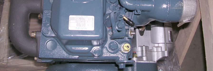
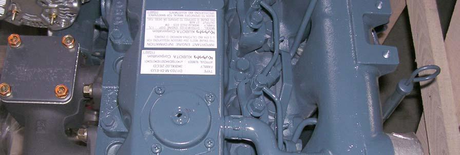
ManufacturerKubota
TypeD 1703 MDI
CoolingWater
Working cycles4
Number of cylinders3
Power DIN 6271 IFN/SAE at 2700 rpmkW25,2
Fixed engine speed rpm2250
Stage 1
Fixed engine speedrpm2700
Stage 2
Valve clearance I/Emm0,20/0,20
Travel pump
ManufacturerHydromatik
TypeA10 VG 28
SystemAxial piston
Displacementcm³/rev.28
High pressure limitationbar380
Charge pressurebar24
Speedrpm2700
Max. flow capacity l/min73
BW 100/120 AD Series 4 B1
BW 100/120 AC Series 4
Travel motor (drums)
Service Training
BW 100/120 AD/AC-4
ManufacturerPoclain
TypeMK 04
Number2
SystemRadial piston motor
Displacementcm³/rev.408
Brakeyes
BW 100/120 AC-4
Travel motor (wheels)
ManufacturerPoclain
TypeMSE 02
Number2
SystemRadial piston motor
Displacementcm³/rev.255
Brakeyes
BW 100/120 AD/AC-4
Vibration pump
ManufacturerBosch
TypeHYZ 11
SystemGear
Displacementcm³/rev.11
Starting pressurebar210
Operating pressurebar 100 +/-60 bar (soil dependent)
BW 100/120 AD Series 4
BW 100/120 AC Series 4
B2
Service Training
Vibration motor
ManufacturerBosch
Type HYZ 8
SystemGear
Displacementcm³/rev.8
Frequency stage 1Hz55
Frequency stage 2Hz70
Amplitudemm0.5
Steering pump
ManufacturerBosch
Type HYZ 8
SystemGear
Displacementcm³/rev.8
max. steering pressurebar140 +/-30 bar
Steering valve
ManufacturerDanfoss
TypeOSPC 80 ON
SystemRotary valve
BW 100/120 AD Series 4 B3
BW 100/120 AC Series 4
Service Training
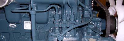
Kubota diesel engine 1703 MDI
The tandem vibratory rollers of series BW 100/120 AD/AC-4 are powered by a water cooled 3-cylinder Kubota diesel engine type 1703 MDI.
The engine is an upright water-cooled four-stroke diesel engine.
BW 100/120 AD Series 4
BW 100/120 AC Series 4
C 1
Cross-section of diesel engine
Service Training
C 2
BW 100/120 AD Series 4
BW 100/120 AC Series 4
View of engine:
Pos. 1 Engine temperature switch Pos. 2 Connection glow plug Pos. 3 Oil dipstick
1 1 3 3 2 2 4 4
Pos. 4 Injection nozzles


C 3
Pos.
Vibration
Pos.
Oil pressure switch 0.6 bar 1 1 3 3 2 2
Service Training BW 100/120 AD Series 4
BW 100/120 AC Series 4 Pump installation on diesel engine Pos. 1 Charge pump
2
pump
3
100/120 AD Series 4 C 4 BW 100/120 AC Series 4
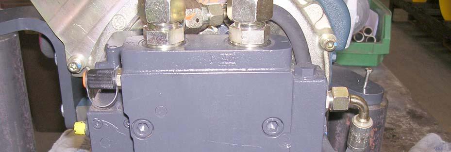
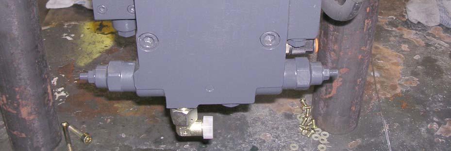
Service Training BW
Pos. 1 Travel pump Pos. 2 Pressure test port A high pressure forward Pos. 3 Pressure test port B high pressure reverse Pos. 4 High pressure relief valves 380 bar 1 1 2 2 3 3 4 4
View of diesel engine, flywheel side
Service
Tests and adjustments
Measuring the compression
Fig. 5:
Compression pressure:
1. Run the engine warm and shut it down. Disassemble the nozzle holders.
2. Install the diesel engine compression tester to the nozzle holder opening.
3. Make sure that the throttle lever is in top position (no injection) and start the engine with the starter motor.
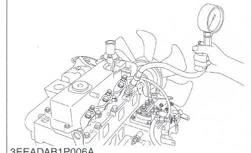
4. Read the max. pressure. Repeat the measurement at least two times.
5. If the measurement is below the permissible limit value check cylinder, piston, valve and cylinder head.
Adjustment values:
C 5
Training BW 100/120 AD Series 4
BW 100/120 AC Series 4
Compression pressure Factory settings 29.4 -32.4 bar Permissible limit value min. 23.5 bar
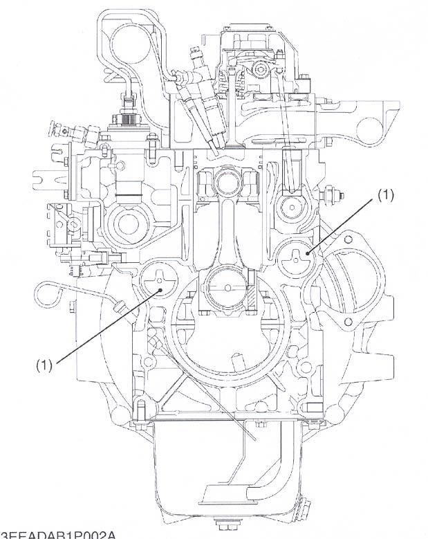
Checking the valve clearance
IMPORTANT:
The valve clearance must only be checked and adjusted when the engine is cold.
The cylinders are counted from the flywheel end, i.e. cylinder 1 is on the flywheel side.
1. Remove the cylinder head cover.
2. Align the mark „1TC“ on the flywheel and the notched part (1) on the plate so that piston no. 1 is in compression stroke or overlaps top dead centre (TDC).
3. Measure the valve clearance marked "1" with a feeler gauge.
4. Correct the clearance by the setscrew if it is not within the limits of the specified factory data.
Valve clearance (cold) Factory settings 0,20 mm
(The values apply for intake and exhaust valves)
BW 100/120 AD Series 4
BW 100/120 AC Series 4
Service Training
C 6
Please note that the TC-mark is only valid for cylinder 1. There is no mark for the other cylinder.
Cylinder 1 is in compression stroke when the TC-mark is visible in the window (2) Now turn the flywheel further, until the other valves overlap top dead centre and adjust the valve clearance accordingly.
Note:
• The "TC"-mark on the flywheel applies only for cylinder no. 1. The other cylinder has no "TC"-mark.
• When the „TC“-mark is aligned with the punched mark on the rear disc, piston no. 1 is in top dead centre position. Now turn the flywheel bz 15° clockwise or anticlockwise to check whether the pistons are in TDC-position (compression position).
(The piston is in TDC when intake and exhaust valves do not move. When both valves are moving, the piston is in overlapping position.)
• Finally turn the flywheel by 360 ° to ensure that „TC“-mark and punched mark match exactly. All valve clearances must be set to the nominal value.
• Turn the flywheel two to three times in anti-clockwise direction to check the valve clearance.
• After adjusting the valve clearance retighten the locking nut of the setscrew.
BW 100/120 AD Series 4
BW 100/120 AC Series 4
Service Training
C 7
Service Training
Engine solenoid:

The machine is equipped with a solenoid which works according to the principle „ENERGIZED TO RUN“. This solenoid has the benefit that the engine will be immediately shut down in case of a fault in the electric system. A disadvantage is the quite costly design of the solenoid with two coils.
Nominal currents of windings:
Pickup winding (PW)51 A
Holding winding (HW)0.7 A
Function of the engine solenoid:
The pickup winding (PW) is directly triggered via potential 30. Once the engine has started and oil pressure is available the voltage to the pickup winding is interrupted and voltage is only applied to the holding winding.
BW 100/120 AD Series 4
BW 100/120 AC Series 4
C 11
Fig. 14:
Solenoid
Service Training
Travel system:
On the machines described in this training manual the travel system consists of a closed hydraulic circuit. It mainly consists of the travel pump with the integrated safety elements, two travel motors, the hydraulic oil filter and the hydraulic oil cooler.
Charge pressure from brake valve
Charge pressure from brake valve

High pressure test ports MA and MB
Charge pressure after hydraulic filter
Leak oil port to tank
The installation of a hydraulic pump with variable displacement into a closed hydraulic circuit is a perfect solution for a hydrostatic travel system, because with this design the travel direction can be reversed without any problems.
The travel pump is flanged to the flywheel side of the diesel engine. It is directly driven by the engine with constant speed.
The tandem gear pump driven by the auxiliary output of the diesel engine consists of a steering/charge pump and a vibration pump. The return flow from the steering valve is fed through the charge oil port into the travel pump.
BW 100/120 AD Series 4
BW 100/120 AC Series 4
D 1
Suggest:
If the above button click is invalid.
Please download this document first, and then click the above link to download the complete manual.
Thank you so much for reading

Service Training
Besides its function of supplying the closed circuit with cool and filtered oil as replacement for leakage and flushing losses, the oil from the charge circuit is also used to release the travel motor integrated brakes:
All safety and control elements needed for the operation in a closed hydraulic circuit are integrated in the travel pump. These are:
High pressure relief valves (380 bar) with integrated boost check valves
Charge pressure relief valve (24 bar)
Servo control
The travel motors (on AD-machines) are hydraulically connected parallel to each other. On AC-machines all three motors are arranged parallel to each other.
BW 100/120 AD Series 4
BW 100/120 AC Series 4
D 2

