
TECHNICAL MANUAL
JANUARY 2003
TM1518
JOHN DEERE
WORLDWIDE COMMERCIAL & CONSUMER EQUIPMENT DIVISION
4X2 and 4X6
North American Version Litho in U.S.A.
Manual Description
This technical manual is written for an experienced technician and contains sections that are specifically for this product. It is a part of a total product support program. The manual is organized so that all the information on a particular system is kept together. The order of grouping is as follows:
•Table of Contents
•Specifications and Information
•Identification Numbers
•Tools and Materials
•Component Location
•Schematics and Harnesses
•Theory of Operation
•Operation and Diagnostics
•Diagnostics
•Tests and Adjustments
•Repair
•Other
NOTE: Depending on the particular section or system being covered, not all of the above groups may be used.
The bleed tabs for the pages of each section will align with the sections listed on this page. Page numbering is consecutive from the beginning of the Safety section through the last section.
We appreciate your input on this manual. If you find any errors or want to comment on the layout of the manual please contact us.
Safety
Specifications and Information
Engine - Gas (Air-Cooled)
Engine - Gas (Liquid-Cooled)
Engine - Diesel
Electrical
Power Train - Gear
Steering
Brakes
Attachments
Engine - Rotary Broom
All information, illustrations and specifications in this manual are based on the latest information at the time of publication. The right is reserved to make changes at any time without notice.
COPYRIGHT© 2003
Deere & Co.
John Deere Worldwide Commercial and Consumer Equipment Division
All rights reserved
Previous Editions
COPYRIGHT©
Introduction
Miscellaneous
INTRODUCTION
Recognize Safety Information
Handle Fluids Safely - Avoid Fires
Be Prepared For Emergencies
This is the safety-alert symbol. When you see this symbol on your machine or in this manual, be alert to the potential for personal injury.
Follow recommended precautions and safe servicing practices.
Understand Signal Words
A signal word - DANGER, WARNING, or CAUTION - is used with the safety-alert symbol. DANGER identifies the most serious hazards.
DANGER or WARNING safety signs are located near specific hazards. General precautions are listed on CAUTION safety signs. CAUTION also calls attention to safety messages in this manual.
Replace Safety Signs
Replace missing or damaged safety signs. See the machine operator’s manual for correct safety sign placement.
•When you work around fuel, do not smoke or work near heaters or other fire hazards.
•Store flammable fluids away from fire hazards. Do not incinerate or puncture pressurized containers.
•Make sure machine is clean of trash, grease, and debris.
•Do not store oily rags; they can ignite and burn spontaneously.
•Be prepared if a fire starts.
•Keep a first aid kit and fire extinguisher handy.
•Keep emergency numbers for doctors, ambulance service, hospital, and fire department near your telephone.
Use Care In Handling and Servicing Batteries
Safety - 1 SAFETY Safety
MIF
MIF
MIF
MIF
Prevent Battery Explosions
•Keep sparks, lighted matches, and open flame away from the top of battery. Battery gas can explode.
•Never check battery charge by placing a metal object across the posts. Use a volt-meter or hydrometer.
•Do not charge a frozen battery; it may explode. Warm battery to 16°C (60°F).
Prevent Acid Burns
•Sulfuric acid in battery electrolyte is poisonous. It is strong enough to burn skin, eat holes in clothing, and cause blindness if splashed into eyes.
Avoid acid burns by:
1.Filling batteries in a well-ventilated area.
2.Wearing eye protection and rubber gloves.
3.Avoiding breathing fumes when electrolyte is added.
4.Avoiding spilling or dripping electrolyte.
5.Use proper jump start procedure.
If you spill acid on yourself:
1.Flush your skin with water.
2.Apply baking soda or lime to help neutralize the acid.
3.Flush your eyes with water for 10 - 15 minutes.
4.Get medical attention immediately.
If acid is swallowed:
1.Drink large amounts of water or milk.
2.Then drink milk of magnesia, beaten eggs, or vegetable oil.
3.Get medical attention immediately.
Wear Protective Clothing
such as earmuffs or earplugs to protect against objectionable or uncomfortable loud noises.
Operating equipment safely requires the full attention of the operator. Do not wear radio or music headphones while operating machine.
Use Care Around High-pressure Fluid Lines
Avoid High-Pressure Fluids
Wear close fitting clothing and safety equipment appropriate to the job.
Prolonged exposure to loud noise can cause impairment or loss of hearing. Wear a suitable hearing protective device
Escaping fluid under pressure can penetrate the skin causing serious injury.
Avoid injury from escaping fluid under pressure by stopping the engine and relieving pressure in the system before disconnecting or connecting hydraulic or other lines. Tighten all connections before applying pressure.
Search for leaks with a piece of cardboard. Protect hands and body from high pressure fluids.
If an accident occurs, see a doctor immediately. Any fluid injected into the skin must be surgically removed within a few hours or gangrene may result. Doctors unfamiliar with this type of injury should reference a knowledgeable medical source. Such information is available from Deere & Company Medical Department in Moline, Illinois, U.S.A.
Avoid Heating Near Pressurized Fluid Lines
Flammable spray can be generated by heating near pressurized fluid lines, resulting in severe burns to yourself and bystanders. Do not heat by welding, soldering, or using a torch near pressurized fluid lines or other flammable materials. Pressurized lines can be accidentally cut when heat goes beyond the immediate flame area.
Safety - 2 SAFETY
MIF
MIF
MIF
Service Machines Safely
Support Machine Properly and Use Proper Lifting Equipment
Tie long hair behind your head. Do not wear a necktie, scarf, loose clothing, or necklace when you work near machine tools or moving parts. If these items were to get caught, severe injury could result.
Remove rings and other jewelry to prevent electrical shorts and entanglement in moving parts.
Use Proper Tools
Use tools appropriate to the work. Makeshift tools and procedures can create safety hazards. Use power tools only to loosen threaded parts and fasteners. For loosening and tightening hardware, use the correct size tools. DO NOT use U.S. measurement tools on metric fasteners. Avoid bodily injury caused by slipping wrenches. Use only service parts meeting John Deere specifications.
Park Machine Safely
Before working on the machine:
1. Lower all equipment to the ground.
2.Stop the engine and remove the key.
3. Disconnect the battery ground strap.
4.Hang a “DO NOT OPERATE” tag in operator station.
If you must work on a lifted machine or attachment, securely support the machine or attachment.
Do not support the machine on cinder blocks, hollow tiles, or props that may crumble under continuous load. Do not work under a machine that is supported solely by a jack. Follow recommended procedures in this manual.
Lifting heavy components incorrectly can cause severe injury or machine damage. Follow recommended procedure for removal and installation of components in the manual.
Work In Clean Area
Before starting a job:
1.Clean work area and machine.
2.Make sure you have all necessary tools to do your job.
3.Have the right parts on hand.
4.Read all instructions thoroughly; do not attempt shortcuts.
Using High Pressure Washers
Directing pressurized water at electronic/electrical components or connectors, bearings, hydraulic seals, fuel injection pumps or other sensitive parts and components may cause product malfunctions. Reduce pressure and spray at a 45 to 90 degree angle.
Illuminate Work Area Safely
Illuminate your work area adequately but safely. Use a portable safety light for working inside or under the machine. Make sure the bulb is enclosed by a wire cage. The hot filament of an accidentally broken bulb can ignite spilled fuel or oil.
Safety - 3 SAFETY
MIF
MIF
MIF
Work In Ventilated Area
Engine exhaust fumes can cause sickness or death. If it is necessary to run an engine in an enclosed area, remove the exhaust fumes from the area with an exhaust pipe extension.
If you do not have an exhaust pipe extension, open the doors and get outside air into the area.
Warning: California Proposition 65 Warning
Gasoline engine exhaust from this product contains chemicals known to the State of California to cause cancer, birth defects, or other reproductive harm. Diesel engine exhaust and some of its constituents are known to the State of California to cause cancer, birth defects, and other reproductive harm.
Remove Paint Before Welding or Heating
Avoid potentially toxic fumes and dust. Hazardous fumes can be generated when paint is heated by welding, soldering, or using a torch. Do all work outside or in a well ventilated area. Dispose of paint and solvent properly. Remove paint before welding or heating: If you sand or grind paint, avoid breathing the dust. Wear an approved respirator. If you use solvent or paint stripper, remove stripper with soap and water before welding. Remove solvent or paint stripper containers and other flammable material from area. Allow fumes to disperse at least 15 minutes before welding or heating.
Avoid Harmful Asbestos Dust
Avoid breathing dust that may be generated when handling components containing asbestos fibers. Inhaled asbestos fibers may cause lung cancer. Components in products that may contain asbestos fibers are brake pads, brake band and lining assemblies, clutch plates, and some gaskets. The asbestos used in these components is usually found in a resin or sealed in some way. Normal handling is not hazardous as long as airborne dust containing asbestos is not generated.
Avoid creating dust. Never use compressed air for cleaning. Avoid brushing or grinding material containing asbestos. When servicing, wear an approved respirator. A special vacuum cleaner is recommended to clean asbestos. If not available, apply a mist of oil or water on the material containing asbestos. Keep bystanders away from the area.
Service Tires Safely
Explosive separation of a tire and rim parts can cause serious injury or death.
Do not attempt to mount a tire unless you have the proper equipment and experience to perform the job. Always maintain the correct tire pressure. Do not inflate the tires above the recommended pressure. Never weld or heat a wheel and tire assembly. The heat can cause an increase in air pressure resulting in a tire explosion. Welding can structurally weaken or deform the wheel.
When inflating tires, use a clip-on chuck and extension hose long enough to allow you to stand to one side and NOT in front of or over the tire assembly. Use a safety cage if available.
Check wheels for low pressure, cuts, bubbles, damaged rims or missing lug bolts and nuts.
SAFETY
Safety - 4
MIF
MIF
Avoid Injury From Rotating Blades, Augers and PTO Shafts
Direct exposure to hazardous chemicals can cause serious injury. Potentially hazardous chemicals used with John Deere equipment include such items as lubricants, coolants, paints, and adhesives.
A Material Safety Data Sheet (MSDS) provides specific details on chemical products: physical and health hazards, safety procedures, and emergency response techniques. Check the MSDS before you start any job using a hazardous chemical. That way you will know exactly what the risks are and how to do the job safely. Then follow procedures and recommended equipment.
Dispose of Waste Properly
Keep hands and feet away while machine is running. Shut off power to service, lubricate or remove mower blades, augers or PTO shafts.
Service Cooling System Safely
Improperly disposing of waste can threaten the environment and ecology. Potentially harmful waste used with John Deere equipment include such items as oil, fuel, coolant, brake fluid, filters, and batteries. Use leakproof containers when draining fluids. Do not use food or beverage containers that may mislead someone into drinking from them. Do not pour waste onto the ground, down a drain, or into any water source. Inquire on the proper way to recycle or dispose of waste from your local environmental or recycling center, or from your John Deere dealer.
Live With Safety
Explosive release of fluids from pressurized cooling system can cause serious burns.
Shut off machine. Only remove filler cap when cool enough to touch with bare hands. Slowly loosen cap to first stop to relieve pressure before removing completely.
Handle Chemical Products Safely
Before returning machine to customer, make sure machine is functioning properly, especially the safety systems. Install all guards and shields.
Safety - 5 SAFETY
MIF
MIF
MIF
MIF
POWER TRAIN - GEAR SPECIFICATIONS
Clutch Mounting Cap Screw Torque
Power Train - Gear Specifications - 489
Specifications General Specifications Drive Belt Width (New). . . . . . . . . . . . . . . . . . . . . . . . . . . . . . . . . . . . . . . . . . . . . . . . . . . . . . . . . . . . . . 30.2 mm (1.19 in.) Drive Belt Width (Minimum). . . . . . . . . . . . . . . . . . . . . . . . . . . . . . . . . . . . . . . . . . . . . . . . . . . . . . . . . . 27 mm (1.063 in.) Clutch Engagement Speed . . . . . . . . . . . . . . . . . . . . . . . . . . . . . . . . . . . . . . . . . . . . . . . . . . . . . . . . . . . .1350 - 1600 rpm Clutch Disengage Speed. . . . . . . . . . . . . . . . . . . . . . . . . . . . . . . . . . . . . . . . . . . . . . . . . . . . . . . . . . . . . . . . . . . 1300 rpm Secondary Clutch Spring Torsion 1 Wrap (for 4x2 models). . . . . . . . . . . . . . . . . . . . . . . . . . . . . . . . . . . . . . . . . . . . . . . . . . . . . . . . . . . 40 - 58 N (9 - 13 lbs) 2 Wraps (for 6x4 models). . . . . . . . . . . . . . . . . . . . . . . . . . . . . . . . . . . . . . . . . . . . . . . . . . . . . . . . . 71 - 89 N (16 - 20 lbs) Secondary Clutch Spring Torsion 120 Degree Wrap (4X2 #W004X2X039280 and up). . . . . . . . . . . . . . . . . . . . . . . . . . . . . . . . . . . . . . 40 - 58 N (9 - 13 lbs) 240 Degree Wrap (6x4 #W006X4X039286 or W006X4D009699 and up). . . . . . . . . . . . . . . . . . . . 71 - 89 N (16 - 20 lbs) Chain Tension (6X4). . . . . . . . . . . . . . . . . . . . . . . . . . . . . . . . . . . . . . . . . . . . . . . . . . . . . . . . . . . 12 - 38 mm (0.5 - 1.5 in.) Chain Size (6X4) . . . . . . . . . . . . . . . . . . . . . . . . . . . . . . . . . . . . . . . . . . . . . . . . . . . . . . . . . . . . . . . . . . . . . . . . . Number 50 Chain Length (6X4). . . . . . . . . . . . . . . . . . . . . . . . . . . . . . . . . . . . . . . . . . . . . . . . . . . . . . . . . . . . . . . . . . . . . . . . 112 Links Secondary
M8 with Left Hand Threads . . . . . . . . . . . . . . . . . . . . . . . . . . . . . . . . . . . . . . . . . . . . . . . . . . . . . . . . . . . 38 N•m (28 lb-ft) M10 with Right Hand Threads. . . . . . . . . . . . . . . . . . . . . . . . . . . . . . . . . . . . . . . . . . . . . . . . . . . . . . . . . 70 N•m (52 lb-ft) Repair Specifications Torques: Rear Rim-to-Axle Bolts . . . . . . . . . . . . . . . . . . . . . . . . . . . . . . . . . . . . . . . . . . . . . . . . . . . . . . . . . . . . . . 88 N•m (65 lb-ft) Transaxle-to-Frame . . . . . . . . . . . . . . . . . . . . . . . . . . . . . . . . . . . . . . . . . . . . . . . . . . . . . . . . . . . . . . . 200 N•m (148 lb-ft) Engine-to-Frame. . . . . . . . . . . . . . . . . . . . . . . . . . . . . . . . . . . . . . . . . . . . . . . . . . . . . . . . . . . . . 28 - 42 N•m (20 - 30 lb-ft) Engine-to-Transaxle Strut (Transaxle Bolt and Lock Nut) . . . . . . . . . . . . . . . . . . . . . . . . . . . . . . . . . . 37 N•m (27 lb-ft) Engine-to-Transaxle Strut (Engine Bolt and Lock Washer) . . . . . . . . . . . . . . . . . . . . . . . . . . . . . . . . . 25 N•m (18 lb-ft) Primary Clutch Mounting Cap Screw Torque. . . . . . . . . . . . . . . . . . . . . . . . . . . . . . . . . . . . . . . . . 50 ± 10 N•m (37 lb-ft) Transaxle: Input Shaft Washer Thickness (Reverse Drive Gear End) Standard . . . . . . . . . . . . . . . . . . . . . . . . . . . . . . . . . . . . . . . . . . . . . . . . . . . . . . . . . . . . . 1.45 - 1.55 mm (0.057 - 0.061 in.) Wear Limit. . . . . . . . . . . . . . . . . . . . . . . . . . . . . . . . . . . . . . . . . . . . . . . . . . . . . . . . . . . . . . . . . . . . . . . 1.20 mm (0.047 in.) Input Shaft Washer Thickness (Forward Drive Sprocket End) Standard . . . . . . . . . . . . . . . . . . . . . . . . . . . . . . . . . . . . . . . . . . . . . . . . . . . . . . . . . . . . . 1.52 - 1.68 mm (0.060 - 0.066 in.) Wear Limit. . . . . . . . . . . . . . . . . . . . . . . . . . . . . . . . . . . . . . . . . . . . . . . . . . . . . . . . . . . . . . . . . . . . . . . 1.30 mm (0.051 in.) Shift Collar Shift Groove Width. . . . . . . . . . . . . . . . . . . . . . . . . . . . . . . . . . . . . . . . . 16.10 - 16.30 mm (0.634 - 0.642 in.) Shift Groove-to-Block Clearance (Maximum) . . . . . . . . . . . . . . . . . . . . . . . . . . . . . . . . . . . . . . . . . . . . . 2 mm (0.08 in.) Spring Free Length. . . . . . . . . . . . . . . . . . . . . . . . . . . . . . . . . . . . . . . . . . . . . . . . . . . . . . . . . . . . . . . 29.50 mm (1.161 in.) Shifter Arm Shifter Block Width . . . . . . . . . . . . . . . . . . . . . . . . . . . . . . . . . . . . . . . . . . . . . . . . . . . . 15.7 - 15.9 mm (0.618 - 0.626 in.) Block-to-Collar Groove Clearance (Maximum) . . . . . . . . . . . . . . . . . . . . . . . . . . . . . . . . . . . . . . . . . . . 2 mm (0.080 in.) Transaxle Case Thrust Washer Thickness. . . . . . . . . . . . . . . . . . . . . . . . . . . . . . . . . . 1.12 - 1.28 mm (0.044 - 0.050 in.) Drain Plug Torque. . . . . . . . . . . . . . . . . . . . . . . . . . . . . . . . . . . . . . . . . . . . . . . . . . . . . . . . . . . . . . . . . . . 39 N•m (29 lb-ft) Shifter Arm Retaining Plate Cap Screw Torque . . . . . . . . . . . . . . . . . . . . . . . . . . . . . . . . . . . . . . . . . 25 N•m (221 lb-in.)
POWER TRAIN - GEAR SPECIFICATIONS
Other Materials
NumberNameUse
TY6305John Deere Clean and Cure PrimerCleans parts and speeds cure of sealant.
TY15139/ TY15443 John Deere SealantSeals transaxle case halves.
TY6333Moly High Temperature EP GreaseApply to splines of transaxle input shaft.
TY22034John Deere SuperLube ®Apply to rollers and cam weigh pivots of primary clutch.
TY9370/TY9477 #242
Thread Lock and Sealer (Medium Strength) Apply to threads of secondar y clutch set screw and ramp tabs. Threads of retaining screw.
Power Train - Gear Specifications - 490
Differential Housing Half Cap Screw and Nut Torque. . . . . . . . . . . . . . . . . . . . . . . . . . . . . . . . . . . . . . 27 N•m (20 lb-ft) Transaxle Case Half Cap Screw Torque PIN ( -4150) . . . . . . . . . . . . . . . . . . . . . . . . . . . . . . . . . . . 26 N•m (230 lb-in.) Transaxle Case Half Cap Screw Torque PIN (4151- ) . . . . . . . . . . . . . . . . . . . . . . . . . . . . . . . . . . . 35 N•m (310 lb-in.) Neutral Start Switch Torque . . . . . . . . . . . . . . . . . . . . . . . . . . . . . . . . . . . . . . . . . . . . . . . . . . . . . . . . . . 39 N•m (29 lb-ft) Transaxle Mounting Bolts. . . . . . . . . . . . . . . . . . . . . . . . . . . . . . . . . . . . . . . . . . . . . . . . . . . . . . . . . . 200 N•m (148 lb-ft) Differential: Bevel Gear Washer Thickness (Standard) . . . . . . . . . . . . . . . . . . . . . . . . . . . . . . . . . . 1.50 - 1.70 mm (0.059 - 0.067 in.) Bevel Gear Washer Thickness (Wear Limit). . . . . . . . . . . . . . . . . . . . . . . . . . . . . . . . . . . . . . . . . . . . 1.30 mm (0.051 in.) Pinion Gear Washer Thickness (Standard) . . . . . . . . . . . . . . . . . . . . . . . . . . . . . . . . . 0.96 - 1.04 mm (0.038 - 0.041 in.) Pinion Gear Washer Thickness (Wear Limit). . . . . . . . . . . . . . . . . . . . . . . . . . . . . . . . . . . . . . . . . . . 0.70 mm (0.028 in.) Differential Lock Collar Groove Width . . . . . . . . . . . . . . . . . . . . . . . . . . . . . . . . . . . . . . . . . . . . . . . . . . . . . . . . . 7.10 - 7.30 mm (0.280 - 0.287 in.) Collar Groove-to-Lock Fork Finger Clearance (Maximum). . . . . . . . . . . . . . . . . . . . . . . . . . . . . . . . . . 2 mm (0.080 in.) Differential Lock Shaft Differential Lock Fork Finger Thickness . . . . . . . . . . . . . . . . . . . . . . . . . . . . . . . . . . . 6.70 - 6.90 mm (0.264 - 0.272 in.) Finger-to-Collar Groove Clearance (Maximum). . . . . . . . . . . . . . . . . . . . . . . . . . . . . . . . . . . . . . . . . . . 2 mm (0.080 in.) Spring Free Length. . . . . . . . . . . . . . . . . . . . . . . . . . . . . . . . . . . . . . . . . . . . . . . . . . . . . . . . . . . . . . . . 93.2 mm (3.669 in.) Spring Working Load. . . . . . . . . . . . . . . . . . . . . . . . . . . . . . . . . . . . . . . . . . 74 mm at 150 N (2.913 in. at 33.72 lb force) Differential Lock Lever Bracket Cap Screw Torque. . . . . . . . . . . . . . . . . . . . . . . . . . . . . . . . . . . . . . 26 N•m (230 lb-in.) Secondary Clutch Mounting Cap Screw Torque . . . . . . . . . . . . . . . . . . . . . . . . . . . . . . . . . . . . . . . . . . 38 N•m (28 lb-ft) Axles: Drive Axle Mounting Nut Torque. . . . . . . . . . . . . . . . . . . . . . . . . . . . . . . . . . . . . . . . . . . . . . . . . . . . . . . 90 N•m (67 lb-ft) Rear Wheel Mounting Cap Screw Torque. . . . . . . . . . . . . . . . . . . . . . . . . . . . . . . . . . . . . . . . . . . . . . . . 88 N•m (65 lb-ft)
POWER TRAIN - GEAR COMPONENT LOCATION
Component Location
Component Location - 4X2
M55708
A- Engine
B- Transaxle
C- Shift Linkage
D- Neutral Start Switch
E- Secondary Clutch
F- Transmission Output Shaft
G- Coupler
H- Axle Housing
I- Axle
J- Internal Wet Brake
K- Drive Belt
L- Primary Clutch
Component Location - 491
- Gear
Power Train
A B C D E F G H I J K L
POWER TRAIN - GEAR COMPONENT LOCATION
Component Location - 6X4
M55709
A- Transaxle
B- Shift Linkage
C- Secondary Clutch
D- Engine
E- Primary Clutch
F- Rear Sprocket and Axle
G- Drive Chain
H- Drive Belt
I- Front Axle and Sprocket
J- Axle Housing
K- Coupler
L- Internal Wet Brake
NOTE: Gas Engine Shown above.
Component Location - 492
- Gear
Power Train
D C B A E F G H I J K L
POWER TRAIN - GEAR THEORY OF OPERATION
Theory of Operation
Clutch Operation
Theory of Operation:
The variable clutch system is speed and load sensitive. The primary and secondary clutches work together, automatically up-shifting (A) and down-shifting (B). This shifting changes the ratio between the clutches, allowing the engine to operate at optimum efficiently, at the peak of its power curve.
The primary clutch (C) is engine speed sensitive, and is mounted on the engine crankshaft. It operates on the principle of centrifugal force. The secondary clutch (D), mounted on the transaxle input shaft, is load sensitive to the rear drive wheels.
Idle Speed:
Primary clutch is spinning with engine crankshaft, but centrifugal force on the weights is not enough to overcome primary spring tension. The primary clutch sheave remains opened wide and does not engage drive belt.
Engagement RPM, Minimum Load, Low Output Speed (E):
Primary clutch sheaves are moving closer together, just starting to move drive belt. Drive belt is running at the top of secondary clutch. A high ratio between the clutches exist, similar to a low gear, as long as there is minimal load.
High Engine RPM, Light Load, High Output Speed (F):
As engine speed increases, centrifugal forces of the cam weights (G) force the primary clutch to up-shift, moving the drive belt to outer pulley diameter, overcoming secondary clutch spring (H). Drive belt then is pulled deep in secondary clutch giving a low ratio, similar to a high gear.
High Engine RPM, Increasing Load, Lower Output Speed
Down-shifting occurs as a load is encountered, such as a hill or soft terrain. The stationary side of the secondary clutch resists forward movement of the wheels, at the same time, torque from the drive belt moves the moveable sheave (I) up the ramp (J). The ramp and spring forces the belt to the outside diameter of the secondary clutch, and overcomes centrifugal forces of the primary clutch causing the down-shifting.
Power Train - Gear Theory of Operation - 493
M56089 G I J D H C A B E F
POWER TRAIN - GEAR THEORY OF OPERATION
Transaxle Component Location and Operation
Function:
The transaxle provides:
•shifting into forward, neutral and reverse.
•differential action between axles for turning
•differential lock, locking axles together for better traction.
Neutral:
In neutral the shift arm (B) centers the shift collar (P) between the forward drive gear (Q), and reverse drive sprocket (E), so they are not engaged. The input shaft (R) rotates freely, not transferring power to the gear on the reduction shaft (O). The shift fork (C) also depresses the neutral start switch (A) only allowing the engine to be started when the transaxle is in neutral.
Forward Power Flow:
When shifted into the forward position, the shift collar (P) engages the forward drive gear (Q). Power is transmitted through the reduction shaft (O) that is in constant mesh with the differential gear (L). The differential gear (L) and assembly rotate, transferring power through the pinion (K) and side gears (M) to the output shafts (H and N).
Reverse Power Flow:
When shifted into reverse, the shift collar (P) engages the reverse drive sprocket (E), that transmits power through the reverse drive chain (D) to the reduction shaft (O). The chain drives the reduction shaft in the opposite direction of the forward gear (Q), rotating the differential gear (L) in the reverse direction. Power is then transferred through the pinion (K) and side gears (M) to the output shafts (H and N).
Differential Lock:
When the differential lock (G) is engaged, the differential lock collar (I) and pins (J) are pushed in, locking the side gears (M) to the differential housing. Power then flows equally out of both output shafts (H and N).
Power Train - Gear Theory of Operation - 494
M56345A
D C B A F E G H Q R P O I N J L M K
POWER TRAIN - GEAR THEORY OF OPERATION
Transaxle Component Location
A- Forward Drive Gear
B- Neutral Switch
C- Shift Fork
D- Reverse Drive Sprocket
E- Reverse Drive Chain
F- Reverse Driven Sprocket
G- Reduction Drive Shaft
H- Brake Actuator Plate
I- Ball and Ramp
J- Right Output Shaft
K- Brake Shaft
M56084
L- Differential Pin
M- Differential Lock Collar
N- Differential Gear
O- Differential Pinion Gears
P- Brake Lever
Q- Left Output Shaft
R- Brake Disks and Plates
S- Reduction Gear Shaft
T- Forward Driven Gear
U- Shift Collar
V- Input Shaft
Power Train - Gear Theory of Operation - 495
V I H F G E B D C P L K J N M O Q T R U S A
Diagnostic Check Points
Test Conditions:
•Engine off
•Rear wheels supported off floor
•Air pressure equal in all dr iving tires. All driving tires close to same radius.
System: Drive Train
(1) Drive belt is in good condition; minimum belt width 27 mm (1-1/16 in.)?
Yes - Go to next step.
No - Replace drive belt.
System: Drive Train
(2) Shift linkage shifts in to forward, neutral and reverse and stays in gear during operation?
Yes - Go to next step.
No - Adjust shift linkage.
(3) Axles rotate smoothly and quietly; no free play in axles, bearings or housings?
Yes - Go to next step.
No - Check axles and housings. Check axle couplers.
(4) Brakes not dragging?
Yes - Go to next step.
No - Adjust brakes.
Power Train - Gear Diagnostics - 496
POWER TRAIN - GEAR DIAGNOSTICS Diagnostics
M55709 2 3 4 5 6 1 7
System: Drive Train
(5) Differential lock engages when in a turn or when wheels slip on one side; disengages when lever is released and torque is equalized on axles?
Yes - Go to next step.
No - Adjust differential lock.
(6) Differential lock produces no ratcheting sound in transaxle?
Yes - Go to next step.
No - Check internal components.
(7) Drive chain (6X4’s) has slack between 8 mm (0.3 in.) and 25 mm (1.0 in.)?
Yes - Go to next check.
No - Adjust drive chain tension.
Test Conditions:
•Engine running at operating temperature and brakes set
•Transmission in neutral position
•Ensure engine is at correct slow idle speed. See appropriate engine specifications.
System: Engine Primary Clutch
(1) Primary clutch disengaged (drive belt not moving)?
Yes - Go to next check.
No - Repair or replace primary clutch.
Test Conditions:
•Engine running at operating temperature and brakes set
•Transmission in neutral position
•Accelerate engine to 1600 rpm
System: Engine Primary Clutch
(1) Primary clutch engages drive belt at 13501600 rpm?
Yes - Go to next check.
No - Replace drive belt. Repair or replace primary clutch.
Test Conditions:
•Engine running at operating temperature and brakes set
•Transmission in neutral position
•Ensure engine is at correct fast idle speed. See appropriate engine specifications.
System: Primary and Secondary Clutch
(1) Primary clutch sheave (movable clutch sheave) moves toward stationary sheave.
Yes - Go to next step.
No - Repair or replace primary clutch.
(2) Secondary clutch sheaves separate?
Yes - Go to next step.
No - Repair or replace secondary clutch.
(3) Secondary clutch fully up-shifted, primary clutch sheaves completely close?
Yes - Go to next check.
No - Repair or replace drive and/or secondary clutches.
Test Conditions:
•Engine running at operating temperature
•Machine on level surface.
System: Machine Performance
(1) Top speed 4.5 seconds minimum per 30 m (100 ft)? Acceleration to 21 m (70 ft) in maximum of 5.5 seconds.
Yes - End of checks.
No - Check drive train components and engine performance. Check for correct engine mounting location.
Power Train - Gear Diagnostics - 497
POWER TRAIN - GEAR DIAGNOSTICS
POWER TRAIN - GEAR TESTS AND ADJUSTMENTS
Tests and Adjustments
Drive Belt Check
Reason:
To check drive belt wear and condition of drive belt.
Procedure:
1.Measure drive belt width. Drive belt must not be less than 27 mm (1-1/16 in.).

2.Check drive belt condition. Drive belt must not be cracked. Some amount of glazing is normal.
Results:
•If drive belt width is less than specification, replace.
•If drive belt is within specification, and there is a performance complaint, check primary clutch and secondary clutch, and run Drive Train Performance Test on next page.
Transaxle Shift Linkage Adjustment

Reason:
•To insure gear shift lever is centered in neutral when transaxle is in neutral.
•To insure both forward and reverse gears will be completely engaged.
•To help prevent shifter from disengaging from gear during operation.
Procedure:
1.Park on level surface and LOCK park brake. Cargo box RAISED, engine OFF, key REMOVED. Plastic shroud under operator’s seats must be bolted securely into place.
2.Move shift lever until detent inside transaxle clicks firmly into the center neutral position.
3.Move shift lever until transaxle is in neutral detent position.
NOTE: With transmission in neutral position the shift lever rod will be perpendicular to the transmission.
4.Loosen shift rod nuts on transaxle as necessary. Adjust the shift rod nuts so the shift lever is contacting the shifter quadrant in the neutral slot

5.Shift into forward and reverse. There should be an even gap between the lever and quadrant in both forward and reverse positions. The shift lever should NOT contact the shift quadrant in either forward or reverse. Adjust the shift linkage if the gaps are uneven.Tighten the shift rod nuts.
6.Shift into neutral and check neutral start.
7.Drive machine over rough ground to check adjustments.
Power Train - Gear Tests and Adjustments - 498
M56085
M56088 and M56344
A B A B 4X2
6X4
POWER TRAIN - GEAR TESTS AND ADJUSTMENTS

Drive Train Performance Tests
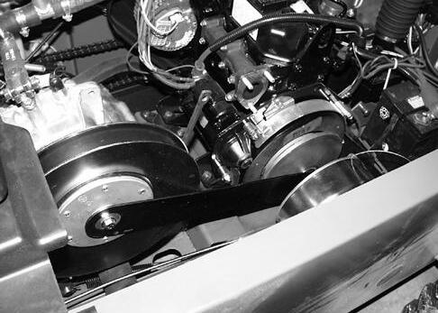
Engagement and Full Up-Shift Check
cCAUTION: Avoid Injury! When operating machine to observe drive train performance, always operate in an area flat and free of obstacles. Use a passenger to observe power train so you can concentrate on driving safely. Never back machine with cargo box raised.
Reason:
To determine if the engine and drive train are operating at peak performance.
Conditions:
•Engine slow idle and fast idle speed set correctly
•Drive belt width at or above minimum specification
•Engine warmed up
Procedure:
1.Transaxle in neutral and park brake set. Start engine.
2.Slowly increase engine rpm. Observe engine rpm when clutch starts to engage and move drive belt.
from bottom to top of primary clutch (A). Watch closely for any hesitation or engine surging. Observe gap between primary clutch movable sheave and stationary sheave. Gap should completely close (B).
4.When approaching idle, watch for a positive disengagement from drive belt.
NOTE: On clutches with some hours of use, system may not disengage as smoothly due to primary clutch spring taking a set and other wear in the drive components.
5.Shut off engine.
Result:
•Clutch should slowly start to engage and move drive belt between 1350 - 1600 rpm. Drive belt should be riding high in primary clutch and low in secondary clutch (C).
•If clutch has harsh engagement, erratic transition, hesitation, or clutch noise (chirping); perform primary clutch lubrication. Check primary clutch for cam weights binding, pivot pins worn, flat spots on rollers or rollers sticking, and no groove in sheave. Repair or replace primary clutch.
•If engine is surging; check engine and governor performance.
•Smooth engagement and transition (up-shift), primary clutch is good. Go to Drive Train Performance Tests; secondary clutch down-shifting check.
4X2 Model Shown
3.Accelerate from idle to wide-open-throttle and back to idle several times. Watch drive belt for a smooth transition
Power Train - Gear Tests and Adjustments - 499
M56086 and MX0763
B A A B C
POWER TRAIN - GEAR TESTS AND ADJUSTMENTS
Secondary Clutch Back-Shifting Check
Reason:
To determine condition of secondary clutch and backshifting performance.
Conditions:
M56090 and MX0764
4X2 Model Shown
•Cargo box raised
•Indoor testing - all rear wheels off ground and machine supported safely on jack-stands.

•Front wheels chocked
•Differential lock engaged
•Tachometer displaying engine speed
Procedure:
cCAUTION: Avoid Injury! Rear wheels will rotate during test. Keep clear!
1.Start engine.
2.Put transaxle in gear.
3.Operate engine at wide open throttle.
Results:
•Engine and wheel speed should remain at constant speed. Drive belt should be riding high in primary clutch and low in secondary clutch.
Procedure:
1.Momentarily load power train by slowly applying brake or park brake until back-shift is made.
2.Quickly observe engine speed, then release brake.
Results:
•Clutches should back-shift as load is increased.
•Drive belt should not squeal or slip.
•If engine speed drops below 2400 rpm or clutches are not back-shifting, see “Secondary Clutch Spring Torsion Check” on page501.
•Check secondary clutch for complete up-shift. Check for load on drive train, such as an engaged brake or failed axle bearings. (See Brake Adjustment procedure.)
Power Train - Gear Tests and Adjustments - 500
C C
Thank you very much for your reading. Please Click Here. Then Get COMPLETE MANUAL.NOWAITING

NOTE:
If there is no response to click on the link above, please download the PDF document first and then clickonit.
POWER TRAIN - GEAR TESTS AND ADJUSTMENTS
Secondary Clutch Spring Torsion Check
Reason:
Verify condition and spring adjustment of secondary clutch.
Conditions:
•Transmission in gear.

•Park brake set.
•Drive belt removed.
Procedure:
IMPORTANT: Avoid damage! Do not damage sheave when clamping Vise-Grip®. Use protective strips of brass or aluminum.
Torque Specification for Movement:
MX1196 and MX0828
1.Clamp vise grip to movable sheave (A).
2.Hook the spring scale into the Vise-Grip® at the outer diameter of the clutch. Pull against Vise-Grip® keeping the spring scale at a right angle to the sheave.
3.Pull sheave/buttons away from ramp approximately 13 mm (1/2 in.).
4.Take the measurement as the sheave is slowly RETURNED toward the ramp, just BEFORE the button contacts the ramp.
NOTE: Setting the spring in a HIGHER # hole INCREASES tension.
Setting the spring in a LOWER # hole DECREASES the tension.
Results:
•Spring force within specification, secondary clutch is OK. Check engine rpm and performance. If a machine has had drive or driven clutch components replaced, the engine rpm must be set to the latest specifications. Be sure the carburetor is clean and the brakes are not dragging.
•Spring force less than specification, up-shift will be faster and slower backshift, reducing engine rpm and response time. Check spring position, set spring tab in next higher number hole (i.e. move from hole “2” to hole”3”). See “Secondary Clutch” on page508. Re-check spring force. Replace spring if still not within specifications.
•Spring force higher than specification, up-shift or acceleration will be slower, reducing engine load, increasing engine rpm and response time. Check spring position, set spring tab in next lower number hole (i.e. move from hole “2” to hole”1”). Recheck spring force. Replace spring (C) if still not within specifications.
Power Train - Gear Tests and Adjustments -
501
Wrap (4x2 models) . . . . . . . . . . . 40 - 58 N (9 - 13 lbs) 2 Wraps (6x4 models) . . . . . . . . . 71 - 89 N (16 - 20 lbs)
Degree Wrap (4X2 #W004X2X039280 and up) . . .40 - 58 N (9 - 13 lbs) 240 Degree Wrap (6x4 #W006X4X039286 or
and up) . . . . . . . 71 - 89 N (16 - 20 lbs)
1
120
W006X4D009699
A B C A
POWER TRAIN - GEAR TESTS AND ADJUSTMENTS

Clutch Center Distance (6X4 Diesel Only)
Reason:
To set optimal distance between clutches. May eliminate creep, grinding noise when shifting, or poor climbing.
Tools:
•JD1175-2-1 Center Gauge
Check Procedure:
1.Remove drive belt.
NOTE: Remove and discard step gauge JDG1175-2-2 from main gauge. Verify the distance between the centers of the tool openings (C, A). The correct distance is 430.91 mm (16.965 in.)
4.Remove or add shims (F) as necessary.
•If the center distance is too long (gauge does not quite get to the secondary clutch hub) fewer shims are required.
•If the center distance is too short (gauge goes past the secondary clutch hub) more shims are required.
If Engine Has Been Removed:
430.91 mm (16.965 in.)
2.Place the open end (A) of the center gauge (B) on the primary clutch shaft (D).
NOTE: When verifying center distance, an incorrect reading will occur if the gauge is installed on the secondary clutch and then forced over the primary clutch.
1.If engine has been removed or motor mounts replaced, install and tighten the four isolators/mounts. Check center distance before the fifth isolator (G) is installed.
3.Verify the closed end (C) of the gauge easily slips onto the secondary clutch hub (E).
2.Place the closed end (C) of clutch center distance gauge (B) over the end of the secondary clutch. Position the open end (A) over the center shaft of the primary clutch.

Power Train - Gear Tests and Adjustments - 502
MIF
MX0768
TCF01411
MIF
C B A
MX0768
E B D F C B A C
