
SERVICE MANUAL
Foreword
The Operator's Manual
You and others can be killed or seriously injured if you operate or maintain the machine without first studying the Operator's Manual. You must understand and follow the instructions in the Operator's Manual. If you do not understand anything, ask your employer or JCB dealer to explain it.
Do not operate the machine without an Operator's Manual, or if there is anything on the machine you do not understand.
Treat the Operator's Manual as part of the machine. Keep it clean and in good condition. Replace the Operator's Manual immediately if it is lost, damaged or becomes unreadable.
03 - Safety - Yours and Others Introduction
All machinery can be hazardous. When a machine is correctly operated and maintained, it is a safe machine to work with. When it is carelessly operated or poorly maintained it can become a danger to you (the operator) and others.
In this manual and on the machine you will find warning messages, you must read and understand them. They inform you of potential hazards and how to avoid them. If you do not fully understand the warning messages, ask your employer or JCB dealer to explain them.
Safety is not just a matter of responding to the warnings. All the time you are working on or with the machine you must be thinking of what hazards there might be and how to avoid them.
Do not work with the machine until you are sure that you can control it.
Do not start any work until you are sure that you and those around you will be safe.
If you are not sure of anything, about the machine or the work, ask someone who knows. Do not assume anything.
Remember:
•Be careful
•Be alert
•Be safe.
06 - Safety Warnings Introduction
In this manual there are safety notices. Each notice starts with a signal word. The signal word meanings are given below.
The signal word 'DANGER' indicates a hazardous situation which, if not avoided, will result in death or serious injury.
The signal word 'WARNING' indicates a hazardous situation which, if not avoided, could result in death or serious injury.
The signal word 'CAUTION' indicates a hazardous situation which, if not avoided, could result in minor or moderate injury.
The signal word 'Notice' indicates a hazardous situation which, if not avoided, could result in machine damage.
The safety alert system symbol (shown) also helps to identify important safety messages in this manual. When you see this symbol your safety is involved, carefully read the message that follows.
09 - General Safety Introduction Training
To operate the machine safely you must know the machine and have the skill to use it. You must abide by all relevant laws, health and safety regulations that apply to the country you are operating in. The operator's manual instructs you on the machine, its controls and its safe operation; it is not a training manual. Ensure that you receive the correct training before operating any machinery. Failing to do so will result in incorrect operation of the machine and you will be putting yourself and others at risk. In some markets, and for work on certain jobsites, you may be required to have been trained and assessed in accordance with an operator competence scheme. Make sure that you and your machine comply with relevant local laws and jobsite requirements – it is your responsibility.
Care and Alertness
All the time you are working with or on the machine, take care and stay alert. Always be careful. Always be alert for hazards.
Clothing
You can be injured if you do not wear the correct clothing. Loose clothing can get caught in the machinery. Keep cuffs fastened. Do not wear a necktie or scarf. Keep long hair restrained. Remove rings, watches and personal jewellery.
Alcohol and Drugs
It is extremely dangerous to operate machinery when under the influence of alcohol or drugs. Do not consume alcoholic drinks or take drugs before or while operating the machine or attachments. Be aware of medicines which can cause drowsiness.
Feeling Unwell
Do not attempt to operate the machine if you are feeling unwell. By doing so you could be a danger to yourself and those you work with.
Mobile Phones
Switch off your mobile phone before entering an area with a potentially explosive atmosphere. Sparks in such an area could cause an explosion or fire resulting in death or serious injury.
Switch off and do not use your mobile phone when refuelling the machine.
Lifting Equipment
You can be injured if you use incorrect or faulty lifting equipment.Youmustidentifytheweightoftheitemto be lifted then choose lifting equipment that is strong enough and suitable for the job. Make sure that lifting equipment is in good condition and complies with all local regulations.
Raised Equipment
Never walk or work under raised equipment unless it is supported by a mechanical device. Equipment which is supported only by a hydraulic device can drop and injure you if the hydraulic system fails or if the control is operated (even with the engine stopped).
Make sure that no-one goes near the machine while you install or remove the mechanical device.
Raised Machine
Never position yourself or any part of your body under a raised machine which is not correctly supported. If the machine moves unexpectedly you could become trapped and suffer serious injury or be killed.
Lightning
Lightning can kill you. Do not use the machine if there is lightning in your area.
Machine Modifications
This machine is manufactured in compliance with prevailing legislative requirements. It must not be altered in any way which could affect or invalidate its compliance. For advice consult your JCB dealer.
00 - General
Introduction
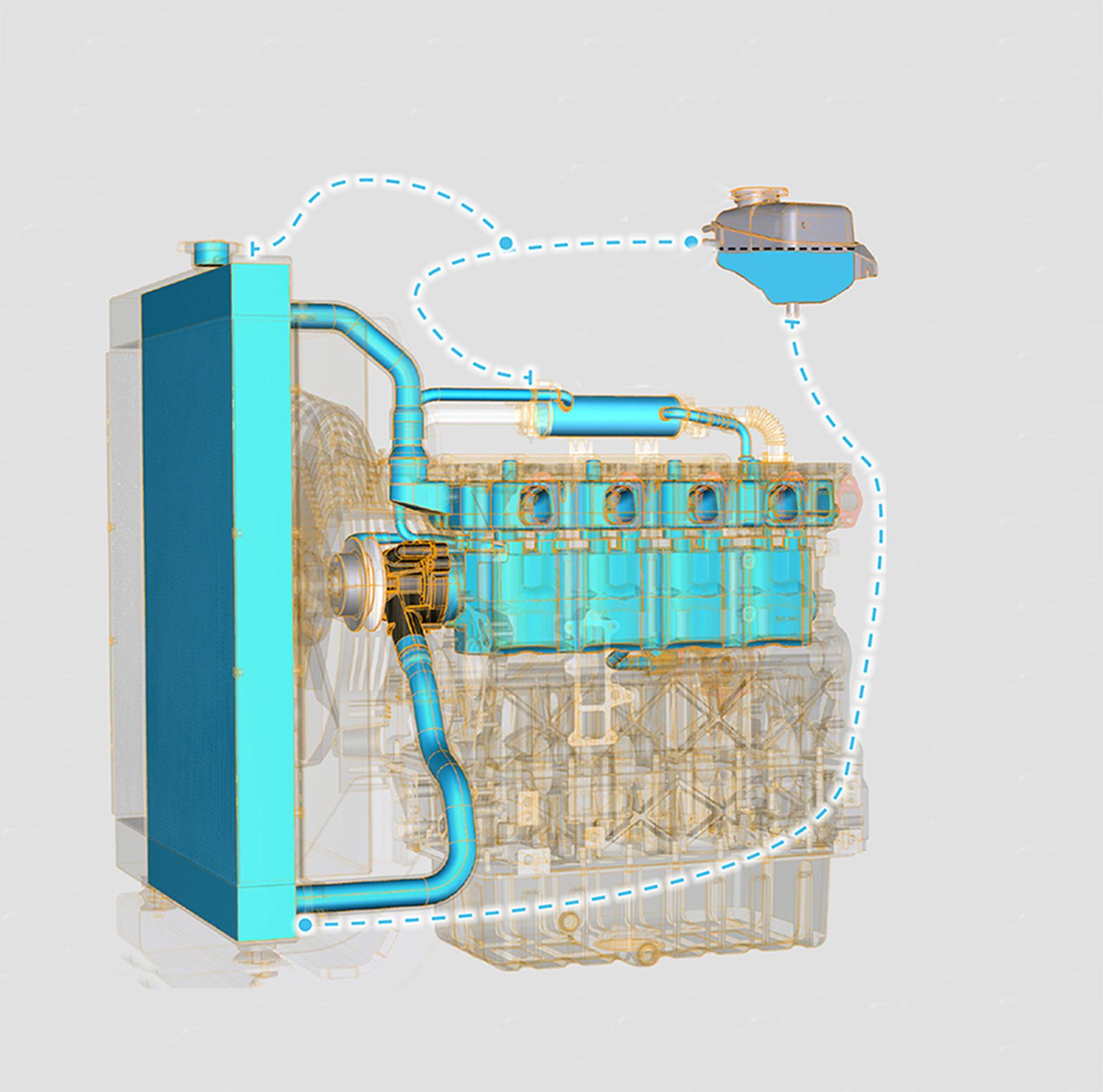
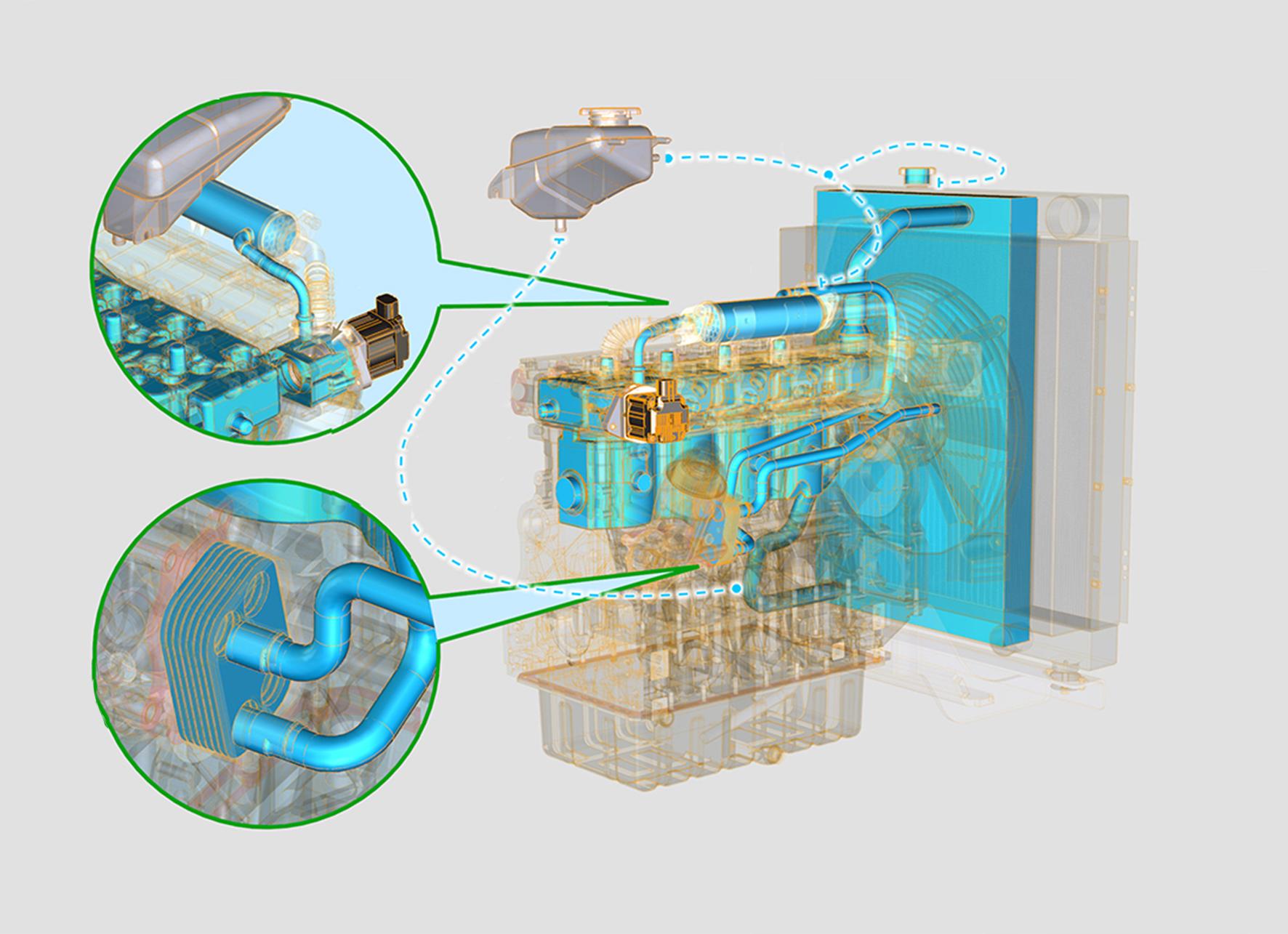
The thermostat is installed on the cylinder head. It is located between the engine and the radiator in the cooling circuit.
The function of the thermostat is to block the flow of coolant to the radiator until the engine has warmed up to a sufficient temperature.
When the engine is cold, no coolant flows through the engine. Once the engine reaches its operating temperature, refer to Cooling System - Technical Data, the thermostat opens. By letting the engine warm up as quickly as possible, the thermostat reduces engine wear, deposits and emissions. Refer to: PIL 21-00-00.
Check (Condition)
1.If the thermostat is suspected of being faulty, perform a thermostat test, to confirm its serviceability.
2.Note that the thermostat is a non-serviceable item. If the thermostat is faulty or damaged it must be renewed.
3.Inspectthesealfordamageorsplits.Ifnecessary replace the seal. Make sure that the seal is correctly installed.
Check (Operation)
WARNING: Personal injury can result from the escaping fluid under pressure. If a pressure indication is shown on the indicator, push the release valve to relieve pressure before removing any hose from the radiator.
1.Remove the thermostat from the engine. Refer to: PIL 21-12-00.
2.Heat the water in a pan until the temperature of the water is equal to the fully open temperature of the thermostat.
2.1.Stir the water in the pan. This will distribute the temperature throughout the pan.
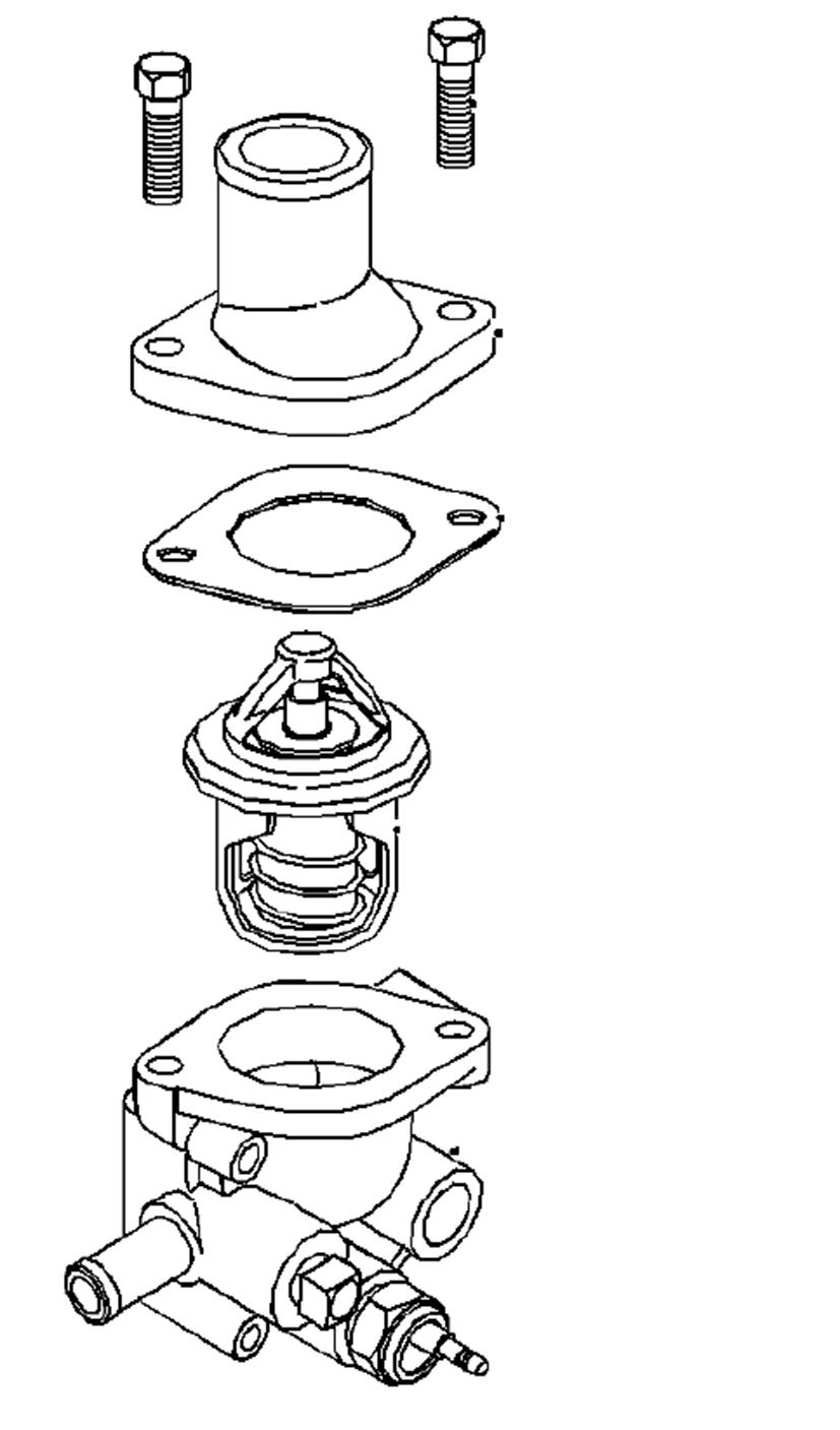
Remove and Install
Remove
1.Drain the cooling system. Refer to: PIL 21-00-00.
2.Remove the bolts.
3.Remove the outlet connection.
4.Identify the orientation of the outlet connection to help installation.
5.Remove the joint.
6.Remove the thermostat from the thermostat housing.
3.Hang the thermostat in the pan of water. The thermostat must be below the surface of the water. The thermostat must be away from the sides and the bottom of the pan.
4.Keep the water at the correct temperature for the specified time.
Duration: 10 min
5.Remove the thermostat.
6.Immediately measure the opening of the thermostat.
7.Make sure that the opening distance is within the specified limit. If not, replace the thermostat.
A Bolt
B Outlet connection
C Joint
D Thermostat
E Thermostat housing
Install
1.Inspect the thermostat for wear, damage and correct operation.
Refer to: PIL 21-12-00.
2.Make sure that the mating surfaces of the outlet connection and the thermostat housing are clean and free from damage.
3.Instal the thermostat to the thermostat housing.
4.Install a new joint.
5.Install the outlet connection to the thermostat housing.
6.Make sure the correct orientation of the outlet connection.
7.Install the bolt and tighten to the correct torque value.
8.Fill the cooling system to the correct level. Refer to: PIL 21-00-00.
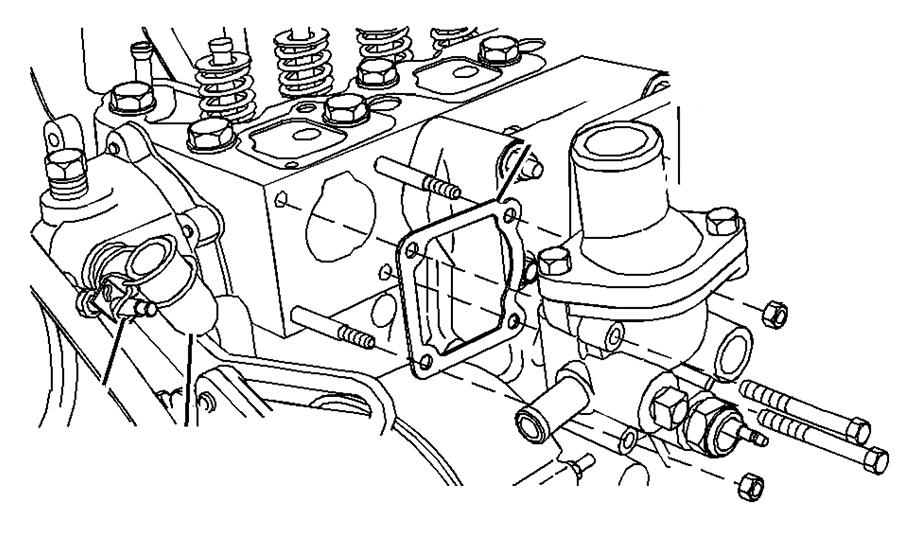
03 - Housing
Remove and Install Remove
1.Drain the cooling system. Refer to: PIL 21-00-00.
2.Loosen the hose clamp and disconnect the hose from the thermostat housing.
3.Remove the bolt and the nut.
4.Remove the thermostat housing from the cylinder head.
5.Remove the joint from the cylinder head.
6.If necessary, remove the thermostat. Refer to: PIL 21-12-00.
Refer to: PIL 21-12-00.
9.Fill the cooling system. Refer to: PIL 21-00-00.
Install
1.Make sure that the mating surfaces of the cylinder head and the thermostat housing are clean and free from damage.
2.Install a new joint to the cylinder head.
3.Install thermostat housing to the cylinder head.
4.Install the bolt and the nut.
5.Tighten the nut to the correct torque value.
6.Connect the hose to thermostat housing.
7.Tighten the hose clamp.
8.If removed, install the thermostat.
00 - General
The engine cooling hoses are essential parts of the cooling system. They carry the liquid coolant between the engine and the radiator/cooling pack.
Health and Safety
CAUTION The cooling system is pressurised when the coolant is hot. When you remove the cap, hot coolant can spray out and burn you. Make sure that the engine is cool before you work on the cooling system.
Component Identification
Check (Condition)
1.Visually inspect the engine and related cooling components for:
1.1.Leaks.
1.2.Cracked, burnt or perished hoses.
1.3.Hose clips are in good condition and tightened to the correct torque value.
Remove and Install
Q
Remove
1.Make the machine safe. Refer to (PIL 01-03).
2.Remove the wheels from the machine. Refer to (PIL 27-29).
3.Remove the drain plug.
4.Drain the oil from the chain case.
5.Loosen the nut.
6.Remove the bolts 2 (x4).
7.Remove the hub adjustment bolt and nut.
8.Swing the hub assembly towards the centre of the machine so that the drive chain is at its slackest position.
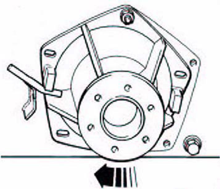
9.Use a suitable bar to wedge the hub. Refer to Figure 315.
9.1.If the front hub is to be removed, both hubs on that side must be rotated to slacken both chains.
Q Bar
10.Remove the spider. Refer to (PIL 27-27).
11.Lift the appropriate chain from the drive sprocket. Make a note that the inner chain drives the front hub, therefore lift the rear chain first.
12.Remove the nut.
13.Remove the hub assembly.
14.Remove the chain from the sprocket.
15.Remove the hub assembly from the chassis.
16.Remove and discard the O-ring.
Install 1.The installation procedure is the opposite of the removal procedure. Additionally do the following step.
2.Apply a thin layer of silicon sealer to the groove before you install the new O-ring.
Consumable: Clear Silicone Sealant
3.Apply a layer of the specified grease to the hub mounting face and O-ring.
Consumable: Special HP Grease
4.Adjust the drive chains as follows:
4.1.Install the hub onto the machine.
4.2.Install the nut.
4.3.Position the adjustment bolt and nut into the slot in the adjustment bracket as shown at position 1. Refer to Figure 317.
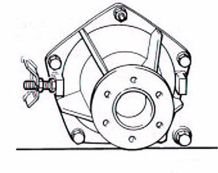
R Position 1
4.4.Use the bolt to push the hub away from the centre of the machine. This will tighten the chain.
4.5.Rotate the sprocket so that one side of the chain is tight.
4.6.Position the hub to give the specified slackness on the opposite side of the chain at the midway point.
Dimension: 25 mm
4.7.Whenthecorrecttensionisachieved,install the bolts 2.
4.8.Tighten the bolts 2 and nut to the correct torque value.
Table 103. Torque Values
Suggest:
If the above button click is invalid.
Please download this document first, and then click the above link to download the complete manual.
Thank you so much for reading

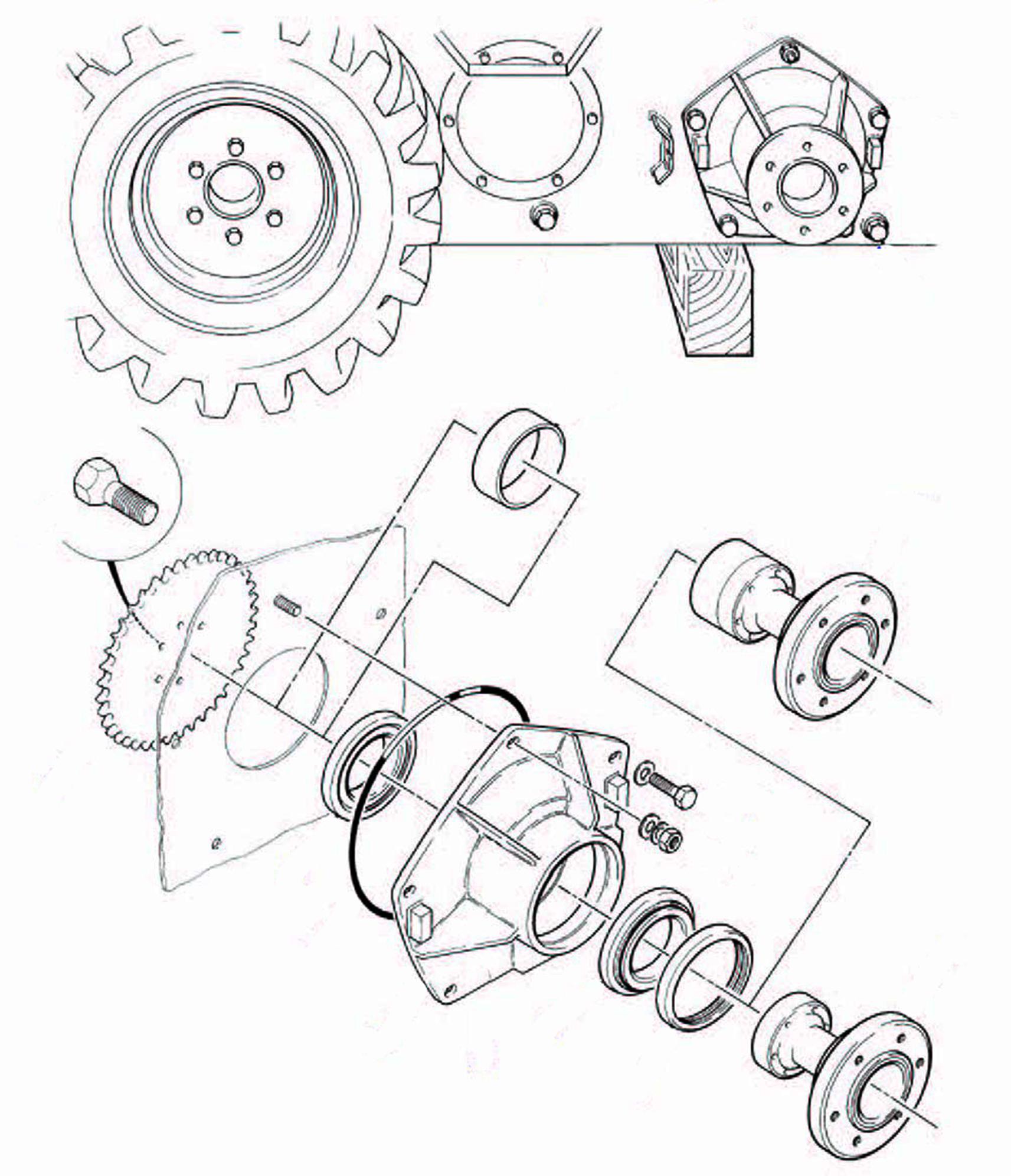
Disassemble and Assemble
2.Make a note that the spacer is only installed to the front hubs.
3.Remove the bolts 1 (x6) and drive sprocket.
4.Support the assembly on the hub face.
5.Press out the stub axle assembly.
6.The bearing 1 will remain in the case. If necessary, remove it separately.
7.The cap of the bearing 2 will also be left in the case. If necessary, remove the cap of the bearing 2.
8.Remove and discard the shaft seal.
1.Use the alphabetical sequence shown on the illustration as a guide to disassembly.
9.Inspect the stub axle and case for wear or damage.
Assemble
1.The assembly procedure is the opposite of the disassembly procedure. Additionally do the following step.
2.Lubricate all the bearings and seals with the specified grease.
Consumable: Special HP Grease
3.Clean the mating faces of the sprocket and hub with the specified cleaner.
Consumable: Cleaner/Degreaser - General purpose solvent based parts cleaner
4.Place the sprocket onto the stub axle.
5.Apply a single run of the specified retainer to each bolt hole in the stub axle.
Consumable: JCB Retainer (High Strength)
6.Apply three runs of the specified retainer to each bolt 1.
Consumable: JCB Retainer (High Strength)
7.Install the bolts.
8.Tighten the bolts evenly to the correct torque valueinadiagonalsequencewhileyourotatethe hub to seat the bearings.
9.Makesurethatthetorquevaluerequiredtorotate the hub after assembly must not be more than the specified value.
Torque: 30 N·m