
Service Repair Manual
Shutdown SIS
Previous Screen
Product: WHEEL LOADER
Model: 950B WHEEL LOADER 65R
Configuration: 950E WHEEL LOADER 65R03089-UP (MACHINE) POWERED BY 3304 ENGINE
Disassembly and Assembly
950B WHEEL LOADER POWER TRAIN
Wheel Spindles
SMCS - 4205-010
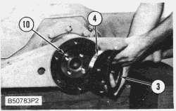
Remove And Install Wheel Spindles

Start By: a. remove wheels, bearings and duo-cone seals


2. Remove O-ring seal (2) from the spindle.
3. Remove bolts (3) and remove the retainer from the spindle.
4. Remove O-ring seal (4) from retainer (5).

NOTE: The following steps are for the installation of the wheel spindles.
5. Install O-ring seal (4) in position on retainer (5).
6. Install retainer (5) on the spline side of the spindle (3).
7. Install O-ring seal (2) on the back of the spindle.
8. Fasten tool (A) and a hoist to spindle (1). Put the spindle in position on the axle housing and install the bolts. Tighten the bolts to a torque of 475 ± 50 N·m (350 ± 37 lb.ft.).
End By:
a. install wheels, bearings and duo-cone seals
Previous Screen
Product: WHEEL LOADER
Model: 950B WHEEL LOADER 65R
Configuration: 950E WHEEL LOADER 65R03089-UP (MACHINE) POWERED BY 3304 ENGINE
Disassembly and Assembly
950B WHEEL LOADER POWER TRAIN
Front Axle Housing

SMCS - 3260-010

Remove And Install Front Axle Housing
Shutdown SIS
Start By:
a. remove tires and rims (front)
b. remove front drive shaft
2. Disconnect brake line (1) from the junction box as shown.
3. Fasten nylon straps (2) and hoist to front axle housing (3) as shown.
4. Remove nuts (4), the bolts and the washers. Carefully lower front axle housing from the machine. The weight of the axle housing is 953 kg (2100 lb.).
NOTE: The following steps are for the installation of the front axle housing.
5. Fasten nylon straps (2) and hoists to axle housing (3).

6. Put axle housing (3) into position on the machine as shown.
7. Install the bolts, the washers and nuts (4) that hold the axle housing to the machine. Tighten the nuts to a torque of 275 ± 35 N·m (200 ± 26 lb.ft.).
8. Connect brake line (1) to the junction box. Remove (bleed) the air from the brake system.

9. Remove tooling (A).
End By:
a. install front drive shaft
b. install tires and rims (front)
Shutdown SIS
Previous Screen
Product: WHEEL LOADER
Model: 950B WHEEL LOADER 65R
Configuration: 950E WHEEL LOADER 65R03089-UP (MACHINE) POWERED BY 3304 ENGINE
Disassembly and Assembly
950B WHEEL LOADER POWER TRAIN
Rear Axle Housing


SMCS - 3260-010
Remove And Install Rear Axle Housing
Start By:
a. remove tires and rims (rear)
b. remove rear drive shaft
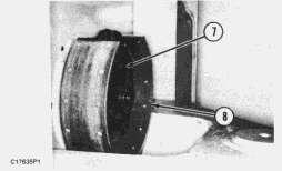
3. Fasten nylon straps (3) and a hoist to rear axle housing (4) as shown.


4. Fasten a chain around the axle housing front support (6) and yoke (5) to hold front support (6) and yoke (5) in position.
5. Remove nuts (7) and the washers from both the front and rear supports.
6. Make sure all lines are disconnected and carefully lower the rear axle housing from the machine. The weight of the rear axle housing is 1089 kg (2400 lb.).
NOTE: The following steps are for the installation of the rear axle housing.
7. Fasten a chain to front support (6) and yoke (5) to hold them in position.
8. Put nylon straps (3) in position on both sides of the rear axle housing. Lift the axle housing into position on the machine.
9. Make sure the dowels in front support (6) are in alignment with the holes in the frame.
10. Install the washers and nuts (7) to both supports. Tighten the nuts to a torque of 475 ± 50 N·m (350 ± 37 lb.ft.).
11. Connect grease line (2) to the rear support and the grease line to the top of the front support.
12. Connect brake line (1) at the top of the axle housing. Remove (bleed) the air from the brake system.
End By:
a. install rear drive shaft
b. install tires and rims (rear)
Shutdown SIS
Previous Screen
Product: WHEEL LOADER
Model: 950B WHEEL LOADER 65R
Configuration: 950E WHEEL LOADER 65R03089-UP (MACHINE) POWERED BY 3304 ENGINE
Disassembly and Assembly
950B WHEEL LOADER POWER TRAIN
Rear Axle Housing Front Support
SMCS - 3268-010

Remove And Install Rear Axle Housing Front Support
Start By:
a. remove rear axle housing
1. Put the rear axle housing on blocks with the differential pinion shaft in a vertical position as shown.
2. Pull yoke (1) off the differential pinion shaft.

3. Fasten nylon straps and a hoist and remove front support (2) from the differential pinion housing. The weight of front support (2) is 34 kg (75 lb.).
4. Remove lip type seals (3) from support (2).
5. Remove ring (5) that holds bearing (4) in the support.
6. Remove lip type seal (6) and push bearing (4) out of the support from the same side ring (5) was removed.

NOTE: The following steps are for the installation of the rear axle housing front support.
7. Use a press and tool (A) to push the bearing in support (2) until it makes contact with the shoulder in its bore.


8. Install ring (5) to hold the bearing in position.
9. Use tooling (B) to install lip type seals (3) in each side of the support. Make sure the lips of the seals are toward the outside of the support.
10. Fasten nylon straps a hoist to the front support and put front support (2) in position on the differential pinion housing. Make sure the side of support (2) with the snap ring in it is toward the yoke end of the pinion shaft. The grease fitting in support (2) must be toward the top of the axle housing.
11. Install yoke (1) on the differential pinion shaft.
End By:
a. install rear axle housing
Copyright 1993 - 2020 Caterpillar Inc.
All Rights Reserved.
Private Network For SIS Licensees.
Fri Apr 10 02:57:49 UTC+0800 2020
Previous Screen
Product: WHEEL LOADER
Model: 950B WHEEL LOADER 65R
Configuration: 950E WHEEL LOADER 65R03089-UP (MACHINE) POWERED BY 3304 ENGINE
Disassembly and Assembly
950B WHEEL LOADER POWER TRAIN
Rear Axle Housing Rear Support
SMCS - 3268-011; 3268-012

Remove Rear Axle Housing Rear Support
Start By:
a. remove rear axle housing
1. Put the rear axle housing on wooden blocks as shown.

2. Remove the bolts and cover (1) from the rear support.
Shutdown SIS


 3. Remove bolts (2), washer (3), plate (4) and the washer from the end of the trunnion.
4. Fasten straps and a hoist to support (5) and remove it from the axle housing. The weight of the support is 39 kg (85 lb.).
5. Remove seal (6) from the support.
6. Use tooling (A) and a press and remove the bearing from the support.
3. Remove bolts (2), washer (3), plate (4) and the washer from the end of the trunnion.
4. Fasten straps and a hoist to support (5) and remove it from the axle housing. The weight of the support is 39 kg (85 lb.).
5. Remove seal (6) from the support.
6. Use tooling (A) and a press and remove the bearing from the support.
7. Remove the bolts and disconnect bracket (7) from the trunnion.
8. Remove bolts (8) and trunnion (9) from the rear axle housing.

9. Remove the O-ring seal from the trunnion.


Install Rear Axle Housing Rear Support
1. Put O-ring seal (2) in position on the back of trunnion (9). Put clean differential oil on the Oring seal.
2. Install trunnion (9) on the axle housing and install the bolts. Tighten the bolts to a torque of 270 ± 25 N·m (200 ± 18 lb.ft.).
3. Connect bracket (7) to the trunnion.

(A) and install the bearing until it is even with the counterbore in support (5).


 4. Use tooling
5. Use tool (A) and install seal (6) in the support. Make sure the lip of the seal is toward the outside as shown. Put clean differential oil on the seal.
6. Fasten straps and a hoist to support (5) and put it in position on the trunnion.
7. Install washer (10), plate (4) and washer (3) in the end of the support as shown.
4. Use tooling
5. Use tool (A) and install seal (6) in the support. Make sure the lip of the seal is toward the outside as shown. Put clean differential oil on the seal.
6. Fasten straps and a hoist to support (5) and put it in position on the trunnion.
7. Install washer (10), plate (4) and washer (3) in the end of the support as shown.
8. Install cover (1) and the bolts on the end of the support. Tighten the bolts to a torque of 475 ± 50 N·m (350 ± 37 lb.ft.).
End By:
a. install rear axle housing

Copyright 1993 - 2020 Caterpillar Inc.
All Rights Reserved. Private Network For SIS Licensees.
Fri Apr 10 02:58:46 UTC+0800 2020
Previous Screen
Product: WHEEL LOADER
Model: 950B WHEEL LOADER 65R
Configuration: 950E WHEEL LOADER 65R03089-UP (MACHINE) POWERED BY 3304 ENGINE
Disassembly and Assembly

950B WHEEL LOADER POWER TRAIN
Front Drive Shaft And Carrier Bearing
SMCS - 3253; 3267-016; 3267-011; 3267-012; 3267-015
Remove Front Drive Shaft And Carrier Bearing
Shutdown SIS
Start By:
a. connection of steering frame lock link
b. remove center drive shaft
NOTE: Block the wheels and release the parking brake prior to the removal operation.
1. Mark the position of lever (2) on the shaft. Remove pin (1), bolt (3), and lever (2).
2. Disconnect grease line (4) from the fitting.


 3. Remove center bolt and washer (5) from the yoke assembly.
4. Attach tool (A) to drum assembly (6). Install tool (B) to tool (A) as shown.
5. Slide the yoke and drum assembly (6) off of the brake shoe assembly and lower them to the ground. The weight of the yoke and drum assembly is 31.7 kg (70 lb.).
6. Remove four bolts (7), and remove brake shoe assembly (8).
7. Remove the top two bolts of bolts (10) and install two 5/8"-11 NC guide bolts (9). Remove the remaining bolts (10).
3. Remove center bolt and washer (5) from the yoke assembly.
4. Attach tool (A) to drum assembly (6). Install tool (B) to tool (A) as shown.
5. Slide the yoke and drum assembly (6) off of the brake shoe assembly and lower them to the ground. The weight of the yoke and drum assembly is 31.7 kg (70 lb.).
6. Remove four bolts (7), and remove brake shoe assembly (8).
7. Remove the top two bolts of bolts (10) and install two 5/8"-11 NC guide bolts (9). Remove the remaining bolts (10).
Install Front Drive Shaft And Carrier Bearing


 8. Remove bolts (11) and (13). Remove straps (12) and (14) that hold the front drive shaft to yoke assembly (15).
9. Remove grease line (16). Use two persons to push the front drive shaft and carrier bearing assembly (17) to the rear of the machine and remove it. The weight of the front drive shaft and carrier bearing assembly is 31.7 kg (70 lb.).
1. Use two persons to position front drive shaft and carrier bearing assembly (17) on the machine. Install grease line (16).
8. Remove bolts (11) and (13). Remove straps (12) and (14) that hold the front drive shaft to yoke assembly (15).
9. Remove grease line (16). Use two persons to push the front drive shaft and carrier bearing assembly (17) to the rear of the machine and remove it. The weight of the front drive shaft and carrier bearing assembly is 31.7 kg (70 lb.).
1. Use two persons to position front drive shaft and carrier bearing assembly (17) on the machine. Install grease line (16).
2. Install straps (12) and (14), and install bolts (11) and (13) that hold the front drive shaft to yoke assembly (15).


3. Tighten bolts (11) and (13) to a torque of 55 ± 7 N·m (41 ± 5 lb.ft.).
 4. Install bolts (10). Remove the two 5/8"-11 NC guide bolts (9), and install the two remaining bolts (10).
5. Position brake shoe assembly (8), and install four bolts (7).
6. Attach tool (A) to drum assembly (6). Install tool (B) to tool (A), and raise and slide the yoke and drum assembly in position as shown.
4. Install bolts (10). Remove the two 5/8"-11 NC guide bolts (9), and install the two remaining bolts (10).
5. Position brake shoe assembly (8), and install four bolts (7).
6. Attach tool (A) to drum assembly (6). Install tool (B) to tool (A), and raise and slide the yoke and drum assembly in position as shown.
7. Install center bolt and washer (5) on the yoke assembly. Tighten the bolt to a torque of 135 ± 15 N·m (100 ± 11 lb.ft.).

8. Connect grease line (4) to the fitting.
9. Align lever (2) with the mark on the shaft. Install lever (2), bolt (3), and pin (1).


End By:
a. install center drive shaft
b. separation of steering frame lock link
Disassemble Front Drive Shaft And Carrier Bearing
Start By:
a. remove front drive shaft and carrier bearing
1. Remove two bolts (1), and remove housing (2) from housing (3).
Assemble Front Drive Shaft And Carrier Bearing


 2. Remove lip type seal (4) from housing (2).
3. Use a press as shown, and press shaft (5) out of bearing (6).
4. Remove O-ring seal (7) from housing (3). Remove bearing (6) from housing (3).
2. Remove lip type seal (4) from housing (2).
3. Use a press as shown, and press shaft (5) out of bearing (6).
4. Remove O-ring seal (7) from housing (3). Remove bearing (6) from housing (3).
1. Use tool group (A) to install the lip seal in housing (3). Make sure the lip of the seal is toward the inside of the housing as shown.
NOTICE
Both lip type seals for the carrier bearing housings must be installed so the lips of the seals are toward the front drive shaft assembly to keep grease out of the parking brake.
2. Lower the temperature of bearing (6), and install in housing (3).
3. Put clean grease on O-ring seal (7), and install it on housing (3) around the bearing.
4. Use a press as shown, and press front drive shaft assembly (8) into the bearing in housing (3).


5. Use tool group (A) to install the seal in housing (2). Make sure the lip of the seal is toward the inside of the housing as shown.

Thank you very much for your reading. Please Click Here. Then Get COMPLETE MANUAL.NOWAITING

NOTE:
If there is no response to click on the link above, please download the PDF document first and then clickonit.
6. Put clean grease on the lip of the seal in housing (2). Install housing (2) on housing (3) and install bolts (1).

End By:
a. install front drive shaft and carrier bearing
Copyright 1993 - 2020 Caterpillar Inc.
All Rights Reserved.
Private Network For SIS Licensees.
Fri Apr 10 02:59:42 UTC+0800 2020
Previous Screen
Product: WHEEL LOADER
Model: 950B WHEEL LOADER 65R
Configuration: 950E WHEEL LOADER 65R03089-UP (MACHINE) POWERED BY 3304 ENGINE
Disassembly and Assembly
950B WHEEL LOADER POWER TRAIN
Center Drive Shaft
SMCS - 3253-010
Remove And Install Center Drive Shaft
Shutdown SIS
1. Make sure the parking brake is released so the drive shaft can be turned.
2. Remove bolts (2) and straps (3) from both ends of drive shaft (1). Remove the drive shaft.
NOTE: The following steps are for the installation of the center drive shaft.
NOTE: Make sure all drive shaft yokes are on the same center line as the center drive shaft is installed.
3. Put drive shaft (1) in position. Install straps (3) and bolts (2).
4. Tighten bolts (2) to a torque of 55 ± 7 N·m (41 ± 5 lb.ft.).

Copyright 1993 - 2020 Caterpillar Inc. All Rights Reserved. Private Network For SIS Licensees.
Previous Screen
Product: WHEEL LOADER
Model: 950B WHEEL LOADER 65R
Configuration: 950E WHEEL LOADER 65R03089-UP (MACHINE) POWERED BY 3304 ENGINE
Disassembly and Assembly
950B WHEEL LOADER POWER TRAIN
Rear Drive Shaft
SMCS - 3253-010
Remove And Install Rear Drive Shaft
Shutdown SIS
1. Remove four bolts (1), and two straps (2) that hold drive shaft (3) on each end to joint groups (4).

2. Remove drive shaft (3) from the machine.
NOTE: The following steps are for the installation of the rear drive shaft.
3. Make sure all the drive shaft yokes in the powertrain are on the same center line.
4. Put drive shaft (3) in position.
5. Install two straps (2) and four bolts (1) on each end. Tighten bolts (1) to a torque of 55 ± 7 N·m (41 ± 5 lb.ft.).
Copyright 1993 - 2020 Caterpillar Inc.
All Rights Reserved.
Fri
Apr 10 03:01:36