
Service
Shutdown SIS
Previous Screen
Product: WHEELED EXCAVATOR
Model: M315C WHEELED EXCAVATOR BDM
Configuration: M315C Excavator BDM02001-UP (MACHINE) POWERED BY 3054E Engine
Disassembly and Assembly
M315C Excavator Machine Systems
Piston Pump (Main Hydraulic) - Disassemble
SMCS - 5070-015
Disassembly Procedure
Table 1
Required Tools
A 1P-1861 Retaining Ring Pliers 1
B 1U-7600 Slide Hammer Puller Gp 1
Start By:
i01904607
A. Remove the main hydraulic pump. Refer to Disassembly and Assembly, "Main Hydraulic Pump - Remove".
Note: Cleanliness is an important factor. Before you begin the disassembly procedure, the exterior of the components should be thoroughly cleaned. This will help to prevent dirt from entering the internal mechanism. Precision components can be damaged by contaminants or by dirt. Perform disassembly procedures on a clean work surface. Keep components covered and protected at all times.
Note: Put identification marks on all hoses, on all hose assemblies, on all wires, and on all tube assemblies for installation purposes. Plug all hose assemblies and all tube assemblies. This helps to prevent fluid loss, and this helps to keep contaminants from entering the system.
Note: Put orientation and location marks on all fittings for installation purposes.
Care must be taken to ensure that fluids are contained during performance of inspection, maintenance, testing, adjusting and repair of the product. Be prepared to collect the fluid with suitable containers before opening any compartment or disassembling any component containing fluids.
Refer to Special Publication, NENG2500, "Caterpillar Tools and Shop Products Guide" for tools and supplies suitable to collect and contain fluids on Caterpillar products.
Dispose of all fluids according to local regulations and mandates.
 Illustration 1
g00902619
1. Remove drain plug (4) from main hydraulic pump (1). Drain the oil from main hydraulic pump (1) into a suitable container.
2. Remove bolts (3) from valve group (2). Remove valve group (2) from main hydraulic pump (1) .
Illustration 1
g00902619
1. Remove drain plug (4) from main hydraulic pump (1). Drain the oil from main hydraulic pump (1) into a suitable container.
2. Remove bolts (3) from valve group (2). Remove valve group (2) from main hydraulic pump (1) .
Personal injury can result from parts and/or covers under spring pressure.
Spring force will be released when covers are removed.
Be prepared to hold spring loaded covers as the bolts are loosened.
3. Remove O-ring seals (5) and O-ring seal (7) .
4. Remove roller (9), spring (8), and piston (6) .
5. Remove plug assembly (11). Remove O-ring seal (10) from plug assembly (11) .

6. Remove piston (12) .
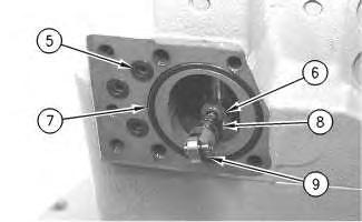 Illustration 2
g00902640
Illustration 3
g00902650
Illustration 2
g00902640
Illustration 3
g00902650
Personal injury can result from parts and/or covers under spring pressure.
Spring force will be released when covers are removed. Be prepared to hold spring loaded covers as the bolts are loosened.
 Illustration 4
g00902662
7. Remove plug (17). Remove spring retainer (16), spring (15), spring (14), and spring retainer (13) from plug (17). Remove O-ring seal (18) from plug (17) .
Illustration 4
g00902662
7. Remove plug (17). Remove spring retainer (16), spring (15), spring (14), and spring retainer (13) from plug (17). Remove O-ring seal (18) from plug (17) .
Personal injury can result from parts and/or covers under spring pressure.
Spring force will be released when covers are removed.
Be prepared to hold spring loaded covers as the bolts are loosened.

Personal injury can result from parts and/or covers under spring pressure.
Spring force will be released when covers are removed.
Be prepared to hold spring loaded covers as the bolts are loosened.


10. Remove retaining ring (33) from valve group (2) .
11. Remove bolt (34) and lever (35) from valve group (2) .


Illustration 9
12. Remove O-ring seal (37) from flange (39) .
13. Remove clutch hub (38) from the pump drive shaft.
14. Remove bolts (36). Remove flange (39) from the main hydraulic pump.
Illustration 8 g00902815 g0090282715. Remove O-ring seal (40) from the back side of flange (39)


 Illustration 10 g00902833
.
Illustration 11 g00902844
Illustration 12 g00902845
Illustration 10 g00902833
.
Illustration 11 g00902844
Illustration 12 g00902845
Personal injury can result from parts and/or covers under spring pressure.
Spring force will be released when covers are removed.
Be prepared to hold spring loaded covers as the bolts are loosened.
Note: The seat adjustment groups (43) and (44) will come apart as pump adapter (41) is being removed from the main hydraulic pump. To prevent mixing of parts, slowly remove pump adapter (41) .
16. Remove bolts (42). Remove pump adapter (41) .
17. Remove seat adjuster group (43). Remove rod (47), piston (46), and spring (45) .
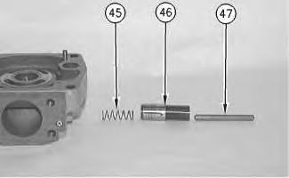
 Illustration 13
g00902859
Illustration 14 g00902860
Illustration 13
g00902859
Illustration 14 g00902860
Illustration 16
18. Remove rod (51) from piston (49).


19. Remove piston (49), spring (50), and bushing (48) .
 Illustration 15
g00902869
g00902872
Illustration 17
g00902888
Illustration 15
g00902869
g00902872
Illustration 17
g00902888
20. Mark the position of port plate (52) in relation to the pump adapter. Remove port plate (52) from pump adapter (41) .


Illustration 18
g00902892
21. Remove bearing (53) from pump adapter (41) .
Illustration 19
g00902897
22. Remove bolts (55) from sensor (54). Remove sensor (54) from main hydraulic pump (1) .
Illustration 20
g00902898
23. Remove bolts (56) from plate (57). Remove plate (57) from main hydraulic pump (1) .
Illustration 21
g00902909
24. Mark the position of the maximum angle stop screw (58) prior to removal from the main hydraulic pump (1). Remove maximum angle stop screw (58). Repeat for the opposite side of the main hydraulic pump.


25. Remove O-ring seal (61). Remove swashplate (60) and barrel assembly (59) as one piece.

 Illustration 22
g00902972
Illustration 23
g00902981
Illustration 22
g00902972
Illustration 23
g00902981
Illustration 24
g00903667
Note: Mark barrel (66), pistons (61), and swashplate (60) for orientation.
26. The swashplate must be heated in order to melt the thread lock. Remove bolts (65) from swashplate (60).

Note: Bolts (65) should be replaced with new bolts.
27. Remove retainers (64) from swashplate (60).
28. Remove barrel assembly (59) from swashplate (60).

Illustration 25
29. Remove pistons (61) from barrel (66).


g00903053
Illustration 26
g00903178
30. Remove retainer plate (62) from pistons (61) .

Illustration 27
g00903180
Illustration 28
31. Remove retainer (67) from barrel (66) .
32. Remove cup springs (68) and shims (69) from barrel (66) .
Note: Mark orientation of cup springs (68) and shims (69) for installation.

Illustration 29
33. Remove plugs (70) and slotted pins (71) .

Illustration 30
34. Remove rods (72) from swashplate (60) .
g00903181 g00903182 g00903209

 Illustration 31
38. Use Tooling (B) to remove seal (76) .
39. Use Tooling (A) to remove retaining ring (77) .
Illustration 34
g00903243
40. Remove shaft (78) from main hydraulic pump (1) .
Illustration 35
g00903244
41. Remove retaining ring (79) from shaft (78) .
42. Remove bearing (80) from shaft (78). Use a suitable press to remove bearing (80) .

Copyright 1993 - 2020 Caterpillar Inc. All Rights Reserved. Private Network For SIS Licensees.

Shutdown SIS
Previous Screen
Product: WHEELED EXCAVATOR
Model: M315C WHEELED EXCAVATOR BDM
Configuration: M315C Excavator BDM02001-UP (MACHINE) POWERED BY 3054E Engine
Disassembly and Assembly
M315C Excavator Machine Systems
Piston Pump (Main Hydraulic) - Assemble
SMCS - 5070-016
Assembly Procedure
Required Tools
the temperature of bearing (80). Install retaining ring (79) to
 Illustration 1
g00903244
1. Install bearing (80) to shaft (78). Raise
shaft (78) .
Illustration 2
g00903358
2. Install shaft (78) to main hydraulic pump (1) .
Illustration 3
g00903222
Illustration 1
g00903244
1. Install bearing (80) to shaft (78). Raise
shaft (78) .
Illustration 2
g00903358
2. Install shaft (78) to main hydraulic pump (1) .
Illustration 3
g00903222
3. Use Tooling (A) to install retaining ring (77) .
4. Use Tooling (G) to install seal (76) .
5. Use Tooling (A) to install retaining ring (75) .
6. Install outer races (74) to main hydraulic pump (1) .
7. Install rods (72) to swashplate (60) .
Illustration 4 g00903220 Illustration 5 g00903209Thank you very much for your reading. Please Click Here. Then Get COMPLETE MANUAL.NOWAITING

NOTE:
If there is no response to click on the link above, please download the PDF document first and then clickonit.
8. Install bearings (73 ) to swashplate (60). Install a rubber band to each bearing (73). The rubber band will hold bearing (73) to swashplate (60) .

9. Carefully install swashplate (60) to main hydraulic pump (1) .

 Illustration 6 g00903415
Illustration 7 g00903418
Illustration 8
g00903482
Illustration 6 g00903415
Illustration 7 g00903418
Illustration 8
g00903482
10. Cut the rubber band on each bearing (73) .
Note: Rods (72) must engage slotted pins (71) .
11. Install plugs (70) and slotted pins (71) .
12. Install the maximum angle stop screw (58). Repeat for the opposite side of the main hydraulic pump.
Illustration 9 g00903182
Illustration 10 g00902909