
Service
Previous Screen
Product: INDUSTRIAL ENGINE
Model: C18 INDUSTRIAL ENGINE JDA
Configuration: C18 Industrial Engine JDA00001-UP
Disassembly and Assembly
C15 and C18 Industrial Engines
Power Take-Off Drive Group - Disassemble
SMCS - 1165-015
S/N - GJE1-UP
S/N - JDA1-UP
S/N - JKG1-UP
S/N - JRE1-UP
S/N - MCW1-UP
S/N - PBN1-UP
S/N - PCZ1-UP
S/N - PDM1-UP
S/N - WJH1-UP
S/N - WRH1-UP
Disassembly Procedure Table 1
Required Tools
Shutdown SIS
Start By:
a. Remove the flywheel. Refer to Disassembly and Assembly, "Flywheel - Remove".

NOTICE
Keep all parts clean from contaminants.
Contaminants may cause rapid wear and shortened component life.
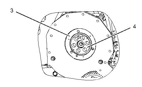
Illustration 1 g01106648
1. Remove bolts (1). Remove adapter (2) from the flywheel housing.
2. Remove the O-ring seal from adapter (2). Use Tooling (B) to remove sleeve bearing (3) from adapter (2).
3. Remove bolts (4). Remove retainer assembly (5) and idler gear (6). Use Tooling (B) and remove the sleeve bearing from idler gear (6).
4. Remove bolts (4). Remove retainer assembly (5) and idler gear (7). Use Tooling (B) and remove the sleeve bearing from idler gear (7).
5. Remove crankshaft gear (8) from Tooling (A). Remove the O-ring seal from the counterbore of the crankshaft gear.
6. Remove gear assembly (9) and gear assembly (10) from the flywheel housing.


7. Remove the bolts and cover (11) from the back side of the flywheel housing. Remove the O -ring seal from the cover. Use Tooling (A) and remove sleeve bearing (12) from the flywheel housing.
8. Remove the bolts and cover (11) from the back side of the flywheel housing. Remove the O -ring seal from the cover. Use Tooling (A) and remove sleeve bearing (13) from the flywheel housing.
Illustration 2 g01106649 Illustration 3 g01106650Previous Screen
Product: INDUSTRIAL ENGINE
Model: C18 INDUSTRIAL ENGINE JDA
Configuration: C18 Industrial Engine JDA00001-UP
Disassembly and Assembly
C15 and C18 Industrial Engines
Power Take-Off Drive Group - Assemble
SMCS - 1165-016
S/N - GJE1-UP
S/N - JDA1-UP
S/N - JKG1-UP
S/N - JRE1-UP
S/N - MCW1-UP
S/N - PBN1-UP
S/N - PCZ1-UP
S/N - PDM1-UP
S/N - WJH1-UP
S/N - WRH1-UP
Assembly Procedure
Table 1
Shutdown SIS
NOTICE
Keep all parts clean from contaminants.
Contaminants may cause rapid wear and shortened component life.
Illustration 1
1. Install sleeve bearing (13) in the flywheel housing with Tooling (B). The split in the sleeve bearing should be located at Angle (Y), which is 15 ± 1 degrees from the horizontal centerline. The bearing should be installed to Depth (Z), which is 2.0 ± 0.5 mm (0.08 ± 0.02 inch).
2. Install sleeve bearing (12) in the flywheel housing with Tooling (B). The split in the sleeve bearing should be located at Angle (X), which is 15 ± 1 degrees from the vertical centerline. The bearing should be installed to Depth (Z), which is 2.0 ± 0.5 mm (0.08 ± 0.02 inch).
3. Install the O-ring seal on cover (11). Install cover (11) and the bolts on the back side of the flywheel housing.

 Illustration 2 g01106649
4. Position gear assembly (9) and gear assembly (10) in the flywheel housing.
Illustration 3 g01106948
5. Use Tooling (B) and install sleeve bearing (3) in adapter (2). Install the O-ring seal on adapter (2).
Illustration 2 g01106649
4. Position gear assembly (9) and gear assembly (10) in the flywheel housing.
Illustration 3 g01106948
5. Use Tooling (B) and install sleeve bearing (3) in adapter (2). Install the O-ring seal on adapter (2).
6. Align the relief groove in the sleeve bearing with the relief groove in the idler gear (6). Use Tooling (B) to install the sleeve bearing in idler gear (6).
7. Position idler gear (6) and retainer (5). Install bolts (4).
8. Align the relief groove in the sleeve bearing with the relief groove in the idler gear (7). Use Tooling (B) to install the sleeve bearing in idler gear (7).
9. Position idler gear (7) and retainer (5). Install bolts (4).
10. Install the O-ring seal in the counterbore of crankshaft gear (8). Lubricate the O-ring seal with clean engine oil. Install crankshaft gear (8) on Tooling (A).
11. Position adapter (2) on the flywheel housing. Apply Tooling (C) to the threads of bolts (1) and install the bolts.
End By:
a. Install the flywheel. Refer to Disassembly and Assembly, "Flywheel - Install".
Copyright 1993 - 2020 Caterpillar Inc.

Previous Screen
Product: INDUSTRIAL ENGINE
Model: C18 INDUSTRIAL ENGINE JDA
Configuration: C18 Industrial Engine JDA00001-UP
Disassembly and Assembly
C15 and C18 Industrial Engines
Vibration Damper and Pulley - Remove and Install
SMCS - 1205-010
Removal Procedure
Table 1
Required Tools
NOTICE
Keep all parts clean from contaminants.
Contaminants may cause rapid wear and shortened component life.
Shutdown SIS
g01058649
1. Remove two bolts (1). Install Tooling (A).
2. Remove remaining bolts (1). Remove pulley (4).

3. Remove vibration damper (3).
4. Remove adapter (2) from the crankshaft.
5. Remove Tooling (A) from the crankshaft.
NOTICE
Keep all parts clean from contaminants.
Contaminants may cause rapid wear and shortened component life.
Thoroughly inspect the viscous damper for signs of leakage or for signs of a dented (damaged) case. Either of these conditions can cause the weight to make contact with the case. This can affect the viscous damper's operation.
Illustration 2
1. Install Tooling (A) in the crankshaft.
2. Install adapter (2) on Tooling (A).
3. Install vibration damper (3) on Tooling (A).
4. Install pulley (4) on Tooling (A).
5. Apply Tooling (B) to bolts (1).
6. Remove Tooling (A) and install the remaining bolts.
Copyright 1993 - 2020 Caterpillar Inc. All Rights Reserved. Private Network For SIS Licensees.
g01058649
Shutdown SIS
Previous Screen
Product: INDUSTRIAL ENGINE
Model: C18 INDUSTRIAL ENGINE JDA
Configuration: C18 Industrial Engine JDA00001-UP
Disassembly and Assembly
C15 and C18 Industrial Engines
Crankshaft Front Seal - Remove
SMCS - 1160-011
Removal Procedure Table 1
Required Tools
B
C 5P-7318 Wear Sleeve Distorter Group 1
Start By:
a. Remove the vibration damper and the pulley. Refer to Disassembly and Assembly, "Vibration Damper and Pulley - Remove and Install".
NOTICE
Keep all parts clean from contaminants.
Contaminants may cause rapid wear and shortened component life.
Note: The crankshaft front seal and the wear sleeve must be replaced at the same time. Once the crankshaft front seal and the wear sleeve are separated, these components can not be used again.
Illustration 1
g01044861
Note: Ensure that you do not damage the front housing with Tooling (B).
Note: If the wear sleeve starts to slide off the crankshaft, go to Step 2.
1. Use Tooling (B) to pry around the lip of wear sleeve (2).
2. Use a small drill in order to puncture three or more holes in crankshaft front seal (1).
3. Use Tooling (A) to remove crankshaft front seal (1).
4. If necessary, use Tooling (C) to remove wear sleeve (2).

Previous Screen
Product: INDUSTRIAL ENGINE
Model: C18 INDUSTRIAL ENGINE JDA
Configuration: C18 Industrial Engine JDA00001-UP
Disassembly and Assembly
C15 and C18 Industrial Engines
Crankshaft Front Seal - Install
SMCS - 1160-012
Installation Procedure
NOTICE
Keep all parts clean from contaminants.
Contaminants may cause rapid wear and shortened component life.
Shutdown SIS
Note: The crankshaft front seal and the wear sleeve must be replaced at the same time. Once the crankshaft front seal and the wear sleeve are separated, these components cannot be used again.
Note: Do not use any type of lubricant during the installation of the crankshaft front seal and the wear sleeve.
1. Before installation of the crankshaft front seal and the wear sleeve, inspect the crankshaft for scratches. Also, inspect the crankshaft for any distortion on the surface that may lead to
an out of round condition. Use a polishing cloth in order to remove any imperfections on the crankshaft.
2. Clean the outside diameter of the crankshaft.
Illustration 1
3. Fasten Tooling (D) to the crankshaft with Tooling (E).
Note: Install the crankshaft front seal with the arrow that shows the direction of crankshaft rotation toward the front of the engine.

4. Position wear sleeve (2) and crankshaft front seal (1) on Tooling (D). Install Tooling (G) on Tooling (D). Lubricate the face of the washer on Tooling (F). Install Tooling (F) on Tooling (D).
5. Tighten Tooling (F) until Tooling (G) contacts Tooling (D).
6. Remove Tooling (F) and Tooling (G) from Tooling (D).
7. Remove Tooling (E) and Tooling (D) from the crankshaft.
End By:
a. Install the vibration damper and the pulley. Refer to Disassembly and Assembly, "Vibration Damper and Pulley - Remove and Install".
g01635160Previous Screen
Product: INDUSTRIAL ENGINE
Model: C18 INDUSTRIAL ENGINE JDA
Configuration: C18 Industrial Engine JDA00001-UP

Disassembly and Assembly
C15 and C18 Industrial Engines
Front Cover - Remove
SMCS - 1166-011
Removal Procedure
NOTICE
Keep all parts clean from contaminants.
Contaminants may cause rapid wear and shortened component life.
Shutdown SIS
1. Remove button head screws (3).
2. Remove nuts (7) and washers (6) from studs (4).
3. Remove front cover (2) from front housing (1).
4. Remove O-ring seal (5) from studs (4).
5. Remove seal (8) from front cover (2).
Previous Screen
Product: INDUSTRIAL ENGINE
Model: C18 INDUSTRIAL ENGINE JDA
Configuration: C18 Industrial Engine JDA00001-UP
Disassembly and Assembly
C15 and C18 Industrial Engines Media
Front Cover - Install
SMCS - 1166-012
Installation Procedure Table 1
Required Tools
Tool Part Number Part Description Qty
A 155-0695 Thread Lock Compound -
NOTICE
Keep all parts clean from contaminants.
Contaminants may cause rapid wear and shortened component life.
Shutdown SIS
Illustration 1
g01268777
1. If studs (4) are loose or the threads are damaged, install new studs in front housing (1). Apply Tooling (A) to the threads of the studs. Install the studs in the front housing. Install O -ring seal (5) on the studs.

2. Install seal (8) in front cover (2).
3. Install front cover (2) on studs (4). Install washers (6) and nuts (7).
4. Install button head screws (3). Tighten the button head screws to a torque of 21 ± 3 N·m (15 ± 2 lb ft).
Copyright 1993 - 2020 Caterpillar Inc. All Rights Reserved. Private Network For SIS Licensees.
Previous Screen
Product: INDUSTRIAL ENGINE
Model: C18 INDUSTRIAL ENGINE JDA
Configuration: C18 Industrial Engine JDA00001-UP
Disassembly and Assembly
C15 and C18 Industrial Engines
Gear Group (Front) - Remove
SMCS - 1206-011
Removal Procedure Table 1
Required Tools
Start By:
a. Remove the front housing. Refer to Disassembly and Assembly, "Housing (Front)Remove".
b. Remove the air compressor, if necessary. Refer to Disassembly and Assembly, "Air Compressor - Remove and Install".
c. Remove the water pump, if necessary. Refer to Disassembly and Assembly, "Water PumpRemove".
d. Remove the auxiliary water pump, if necessary. Refer to Disassembly and Assembly, "Auxiliary Water Pump - Remove".
e. Remove the fuel transfer pump, if necessary. Refer to Disassembly and Assembly, "Fuel Transfer Pump - Remove".
NOTICE
Keep all parts clean from contaminants.
Contaminants may cause rapid wear and shortened component life.
NOTICE
Do not turn the crankshaft or the camshaft while the camshaft gear is removed. If the front gear group is not correctly timed during installation, interference can occur between the pistons and the valves, resulting in damage to the engine.
Note: Be sure to mark the orientation of each of the gears for installation purposes.
 Illustration 1 g01008429
1. Remove bolts (2) and thrust plate (1).
Illustration 1 g01008429
1. Remove bolts (2) and thrust plate (1).
Thank you very much for your reading. Please Click Here. Then Get COMPLETE MANUAL.NOWAITING

NOTE:
If there is no response to click on the link above, please download the PDF document first and then clickonit.
Illustration 2 g01008430

Illustration 3 g01008431
 2. Remove sealing plate (3) and adapter (4).
3. Remove O-ring seal (5) and O-ring seal (6) from sealing plate (3).
2. Remove sealing plate (3) and adapter (4).
3. Remove O-ring seal (5) and O-ring seal (6) from sealing plate (3).
Illustration 4
4. Remove bolts (8), plate (9), and adjustable idler gear assembly (7).
g01101536
5. Use Tooling (A) and remove the sleeve bearing from adjustable idler gear assembly (7).
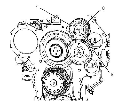
Illustration 5 g01101045
6. Remove bolts (11), plate (12), and idler gear assembly (10).
7. Use Tooling (A) and remove the sleeve bearing from idler gear assembly (10).
