
SERVICE MANUAL CX250D CX250D Long Reach Crawler Excavator Part number 47843013 English May 2015 © 2015 CNH Industrial Italia S.p.A. All Rights Reserved.
SER VICE MANUAL
CX250D Crawler excavators version (TIER4 FINAL) - Market
CX250D Crawler excavators NLC version (TIER4 FINAL) - EU Market
CX250D Long Reach Crawler excavators Long Reach (TIER4 FINAL) - Market

47843013 21/05/2015
Contents INTRODUCTION Engine . . . . . . . . . . . . . . . . . . . . . . . . . . . . . . . . . . . . . . . . . . . . . . . . . . . . . . . . . . . . . . . . . . . . . . . . . . . . . . . . . . . . . . . [10.001] Engine and crankcase . . . . . . . . . . . . . . . . . . . . . . . . . . . . . . . . . . . . . . . . . . . . . . . . . . . . . . . . . . . . . 10.1 [10.102] Pan and covers . . . . . . . . . . . . . . . . . . . . . . . . . . . . . . . . . . . . . . . . . . . . . . . . . . . . . . . . . . . . . . . . . . . . 10.2 [10.106] V alve drive and gears . . . . . . . . . . . . . . . . . . . . . . . . . . . . . . . . . . . . . . . . . . . . . . . . . . . . . . . . . . . . . . 10.3 [10.101] Cylinder heads . . . . . . . . . . . . . . . . . . . . . . . . . . . . . . . . . . . . . . . . . . . . . . . . . . . . . . . . . . . . . . . . . . . . . 10.4 [10.105] Connecting rods and pistons . . . . . . . . . . . . . . . . . . . . . . . . . . . . . . . . . . . . . . . . . . . . . . . . . . . . . . . 10.5 Crankshaft and flywheel Fuel tanks Fuel filters [10.218] Fuel injection system . . . . . . . . . . . . . . . . . . . . . . . . . . . . . . . . . . . . . . . . . . . . . . . . . . . . . . . . . . . . . . . 10.9 [10.202] Air cleaners and lines . . . . . . . . . . . . . . . . . . . . . . . . . . . . . . . . . . . . . . . . . . . . . . . . . . . . . . . . . . . . 10.10 [10.250] T urbocharger and lines . . . . . . . . . . . . . . . . . . . . . . . . . . . . . . . . . . . . . . . . . . . . . . . . . . . . . . . . . . . 10.1 1 Intake and exhaust manifolds and muf fler Selective Catalytic Reduction (SCR) exhaust treatment Exhaust Gas Recirculation (EGR) - Diesel Particulate Filter (DPF) exhaust treatment [10.400] Engine cooling system . . . . . . . . . . . . . . . . . . . . . . . . . . . . . . . . . . . . . . . . . . . . . . . . . . . . . . . . . . . 10.15 [10.414] Fan and drive . . . . . . . . . . . . . . . . . . . . . . . . . . . . . . . . . . . . . . . . . . . . . . . . . . . . . . . . . . . . . . . . . . . . 10.16 [10.310] Aftercooler . . . . . . . . . . . . . . . . . . . . . . . . . . . . . . . . . . . . . . . . . . . . . . . . . . . . . . . . . . . . . . . . . . . . . . . . 10.17 [10.304] Engine lubrication system . . . . . . . . . . . . . . . . . . . . . . . . . . . . . . . . . . . . . . . . . . . . . . . . . . . . . . . . 10.18 Hydraulic systems . . . . . . . . . . . . . . . . . . . . . . . . . . . . . . . . . . . . . . . . . . . . . . . . . . . . . . . . . . . . . . . . . . . . . . . [35.000] Hydraulic systems . . . . . . . . . . . . . . . . . . . . . . . . . . . . . . . . . . . . . . . . . . . . . . . . . . . . . . . . . . . . . . . . . . 35.1 Reservoir , cooler , and filters V ariable displacement pump [35.102] Pump control valves . . . . . . . . . . . . . . . . . . . . . . . . . . . . . . . . . . . . . . . . . . . . . . . . . . . . . . . . . . . . . . . . 35.4 [35.359] Main control valve . . . . . . . . . . . . . . . . . . . . . . . . . . . . . . . . . . . . . . . . . . . . . . . . . . . . . . . . . . . . . . . . . . 35.5 47843013 21/05/2015
Hydraulic hand control
Hydraulic foot control
Hydraulic swing system
Hydraulic travel system
Hydraulic central joint
Boom hydraulic system
Dipper hydraulic system
Excavator and backhoe bucket hydraulic system
Hammer and rotating bucket hydraulic system
Pilot system
1
and
. . . . . . . . . . . . . . . . . . . . . . . . . . . . . . . . . . . . . . . . . . . . . . . . . . . . . . . . . . . . . . . . . [39.140] Ballasts and
. . . . . . . . . . . . . . . . . . . . . . . . . . . . . . . . . . . . . . . . . . . . . . . . . . . . . . . . . . . . . . 39.1
racks
. . . . . . . . . . . . . . . . . . . . . . . . . . . . . . . . . . . . . . . . . . . . . . . . . . . . . . . .
racks [48.134] T rack tension units . . . . . . . . . . . . . . . . . . . . . . . . . . . . . . . . . . . . . . . . . . . . . . . . . . . . . . . . . . . . . . . . . 48.3 [48.138] T rack rollers . . . . . . . . . . . . . . . . . . . . . . . . . . . . . . . . . . . . . . . . . . . . . . . . . . . . . . . . . . . . . . . . . . . . . . . . 48.4 Cab climate control . . . . . . . . . . . . . . . . . . . . . . . . . . . . . . . . . . . . . . . . . . . . . . . . . . . . . . . . . . . . . . . . . . . . . Heating Air conditioning Electrical systems . . . . . . . . . . . . . . . . . . . . . . . . . . . . . . . . . . . . . . . . . . . . . . . . . . . . . . . . . . . . . . . . . . . . . . . [55.000] Electrical system . . . . . . . . . . . . . . . . . . . . . . . . . . . . . . . . . . . . . . . . . . . . . . . . . . . . . . . . . . . . . . . . . . . 55.1 [55.100] Harnesses and connectors . . . . . . . . . . . . . . . . . . . . . . . . . . . . . . . . . . . . . . . . . . . . . . . . . . . . . . . . . 55.2 [55.525] Cab engine controls . . . . . . . . . . . . . . . . . . . . . . . . . . . . . . . . . . . . . . . . . . . . . . . . . . . . . . . . . . . . . . . . 55.3 [55.015] Engine control system . . . . . . . . . . . . . . . . . . . . . . . . . . . . . . . . . . . . . . . . . . . . . . . . . . . . . . . . . . . . . . 55.4 [55.201] Engine starting system . . . . . . . . . . . . . . . . . . . . . . . . . . . . . . . . . . . . . . . . . . . . . . . . . . . . . . . . . . . . . 55.5 [55.301] Alternator . . . . . . . . . . . . . . . . . . . . . . . . . . . . . . . . . . . . . . . . . . . . . . . . . . . . . . . . . . . . . . . . . . . . . . . . . . . 55.6 [55.302] Battery . . . . . . . . . . . . . . . . . . . . . . . . . . . . . . . . . . . . . . . . . . . . . . . . . . . . . . . . . . . . . . . . . . . . . . . . . . . . . . 55.7 47843013 21/05/2015
Frames
ballasting
supports
T
and track suspension
T rack frame and driving wheels T
Cold start aid Fuel tank system Fuel injection system Engine intake and exhaust system 1 Selective Catalytic Reduction (SCR) electrical system Exhaust Gas Recirculation (EGR) electrical system Engine cooling system Engine oil system Electronic modules Cab controls Hydraulic system control [55.051] Cab Heating, V entilation, and (HV AC) controls . . . . . . . . . . . . . . . . . 55.19 [55.050] Heating, V entilation, and Air-Conditioning (HV AC) control system . . . . . . . . . . . . . . . 55.20 [55.524] Cab controls (Lift arm, Boom, Dipper , Bucket) . . . . . . . . . . . . . . . . . . . . . . . . . . . . . . . . . . . 55.21 Swing control system T ravel control system Camera Wiper and washer system External lighting Cab lighting W arning and instruments system F AUL T CODES Booms, dippers, and buckets . . . . . . . . . . . . . . . . . . . . . . . . . . . . . . . . . . . . . . . . . . . . . . . . . . . . . . . [84.910] Boom . . . . . . . . . . . . . . . . . . . . . . . . . . . . . . . . . . . . . . . . . . . . . . . . . . . . . . . . . . . . . . . . . . . . . . . . . . . . . . . 84.1 Dipper arm Bucket Platform, cab, bodywork, and decals . . . . . . . . . . . . . . . . . . . . . . . . . . . . . . . . . . . . . . . . . . . . . [90.150] Cab . . . . . . . . . . . . . . . . . . . . . . . . . . . . . . . . . . . . . . . . . . . . . . . . . . . . . . . . . . . . . . . . . . . . . . . . . . . . . . . . . 90.1 47843013 21/05/2015
Cab glazing [90.1 18] Protections and footboards . . . . . . . . . . . . . . . . . . . . . . . . . . . . . . . . . . . . . . . . . . . . . . . . . . . . . . . . . 90.3 operator seat Engine hood and panels 47843013 21/05/2015
INTRODUCTION 47843013 21/05/2015 1
Foreword - Important notice regarding equipment servicing
All repair and maintenance work listed this manual must carried out only qualified dealership strictly complying with the instructions and whenever the special
Anyone who performs repair and maintenance operations without complying with the procedures provided herein shall responsible for any subsequent
The manufacturer and all the organizations its distribution chain, including - without limitationnational, regional, local reject any responsibility for damages caused parts and / components not approved the facturer , including those used for the servicing repair the product manufactured marketed the manufacturer any case, warranty given attributed the product manufactured marketed the manufacturer case damages caused parts and / components not approved the manufacturer
The manufacturer reserves the right make improvements design and changes specifications any time without notice and without incurring any obligation install them units previously and illustrative material herein are accurate known time publication but are subject change without notice.
case refer your CASE CONSTRUCTION Sales and Service
INTRODUCTION
47843013 21/05/2015 3
INTRODUCTION
Safety rules
Personal safety
This the safety alert used alert you potential personal injury Obey all safety messages that follow this symbol avoid possible death injury

Throughout this manual you will find the signal words W and CAUTION followed special These precautions are intended for the personal safety you and those working with
Read and understand all the safety messages this manual before you operate service the
DANGER indicates a hazardous situation not will result death serious injury
W
ARNING indicates a hazardous situation not could result death serious injury
CAUTION indicates a hazardous situation not could result minor moderate injury
F AILURE T O FOLLOW DANGER, W ARNING, AND CAUTION MESSAGES COULD RESUL T DEA SERIOUS INJUR Y .
Machine safety
NOTICE: Notice indicates a situation that, not avoided, could result machine property damage.
Throughout this manual you will find the signal word Notice followed special instructions prevent machine property damage. The word Notice used address practices not related personal safety .
Information
NOTE: Note indicates additional information that clarifies other information this
Throughout this manual you will find the word Note followed additional information about a step, other information the The word Note not intended address personal safety property
47843013 21/05/2015 4
Safety rules – General information
Cleaning
Clean the metal parts with cleaning solution that meets the standard and steam (except for bearings)
After cleaning, dry well, and inject oil all parts.
Also inject oil into the bearings after
Inspection
When disassembling check all the there are any worn damaged replace Inspect carefully prevent initial
Bearing
Replace any loose
Air dry bearings before installing
Needle bearing
When inserting needle very careful not damage
Apply grease the section where the needle bearing will
Gear
Check that there wear and Oil seal, Oring, gasket
Always install new oil O - and
Apply grease sections where oil seals and O - rings will
Shaft
Check that there wear and
Check the bearings and check for damaged oil seals the shaft.
Service parts
Install CASE CONSTRUCTION genuine service parts.
When placing order , check the parts contains the CASE CONSTRUCTION genuine part
Any breakdowns arising from the installation non - genuine parts are not covered the warranty
Lubricants (fuel, hydraulic oil)
Use the oil from the specified company specified the manual service
Any breakdowns arising from any fuel hydraulic oil other than those specified are not covered the warranty
INTRODUCTION
47843013 21/05/2015 5
SER VICE MANUAL
Engine
CX250D Crawler excavators version (TIER4 FINAL) - Market
CX250D Crawler excavators NLC version (TIER4 FINAL) - EU Market
CX250D Long Reach Crawler excavators Long Reach (TIER4 FINAL) - Market
47843013 21/05/2015
Engine - Engine and crankcase
Engine - General specification
Engine main specifications
Item Engine model 4HK1 T ype Diesel / 4 - cycle / water - inline 4 cylinder OHC Shape combustion chamber Direct injection type Cylinder liner type Dry type Cylinder bore x stroke 1 ( ) x 125 ( ) Displacement 5.193 L ( 317 in³ ) Compression ratio Compression pressure MPa ( 469 psi ) 200 RPM Idling speed 800 RPM Intake 0.4 ( 0.016 ) While cool V alve clearance Exhaust 0.4 ( 0.016 ) While cool Ignition method Compression ignition Injection order 2 Lubrication system Lubrication type Compression type Oil pump type Gear type Lubrication oil amount - L ( - gal ) Oil filter type Full - flow / partial flow integrated filter (Cartridge type) Oil cooling type Built - water cooling Cooling system Cooling type W ater cooling Radiator type Corrugated fin (Pressure type) W ater pump type Centrifugal belt type Thermostat type 2 - wax type unit 76.5 ( 170 ) With jiggle valve T ype 1 ( 180 ) Without jiggle valve ( 185 ) With jiggle valve Thermostat valve open valve temperature T ype 2 ( 180 ) Without jiggle valve Coolant capacity 14.5 L ( 3.8 gal ) Fuel system Injection pump type Electronic control common rail (fuel rail) type Governor type Electronic type T imer type Electronic type Injection nozzle type Multi - hole type 7 inner diameter Ø 0.14 ( 0.0055 ) Charging system Generator type type Output V A Regulator type Starter system Starter type Reduction type Output V 5.0 Preheat system type Glow plug Glow plug standard voltage / current V 3.5 A 47843013 21/05/2015 10.1 [10.001] / 3
Engine - Engine and crankcase
main specifications Item Specifications W ater pump Centrifugal impeller method Pulley ratio Thermostat W pellet type ( 194 ) With jiggle valve T ype 1 ( 203 ) Without jiggle valve 100 ( 212 ) With jiggle valve Full open temperature T ype 2 ( 203 ) Without jiggle valve
system main specifications Generator Item Data Isuzu parts number 8980921 161 Nominal output V / A Rated speed 5000 RPM Regulator type type Regulated voltage 27.529.5 V W eight ( ) Starter T ype (Manufacturer) Nikko V oltage V Output 5 ( 6.8 ) Rated T ime s pinion gears Direction rotation (toward pinion) Clockwise W eight 8.0 ( 17.6 ) Current / voltage A less / V - load characteristics Speed 3300 RPM more Current / voltage 400 A / 18.5 V T orque 28.4 ( 20.95 ) more Load characteristics Speed 1250 RPM more Current / voltage 1400 A less / 9 V Locking characteristics T orque N·m ( ) more 47843013 21/05/2015 10.1 [10.001] / 4
Cooling system
Electrical
Engine - Engine and crankcase

Engine - Identification
Engine number
Engine number stamping 47843013
SMIL13CEX171 1GB 121/05/2015 10.1 [10.001] / 5
Engine - Static description
The control provided the control unit applies the range from injection air intake and exhaust, including fuel injection quantity , injection air intake and idling
Cylinder block
The cylinder block made cast and has equal center distance for each bore and a high rigidity , and the center the crankshaft matches the center the T ighten the bearing cap using the plastic region rotational angle tightening method with the ladder frame
Cylinder liner
A cylinder liner that matches with the cylinder block bore inner diameter and the identification number stamped the left side the cylinder
Piston
The piston a strut cast autothermatic piston made aluminum alloy , and the combustion chamber the round - entrant type.
Cylinder head
The cylinder head made cast iron and has four valves per cylinder . The angle tightening method has been adopted for the cylinder head bolt further improve its reliability and durability
Crankshaft
The crankshaft uses tuf ftrided and each the journal diameter grades are marked the 1 balance
EGR system
The EGR system controlled the engine control module (ECM) according various including the water engine and engine recirculate the exhaust gas for The primary components are the EGR EGR cooler , and various
Connecting rod cap bolt
The angle tightening method has been adopted for the connecting rod cap bolt further improve its reliability and durability
Common rail (fuel rail) type electronic control injection system
The common rail (fuel rail) type electronic control injection system consists the fuel supply pump that sets the target pressure the high pressure fuel supply the fuel, the common rail (fuel rail) that measures the high - pressure fuel, and the fuel injector that injects the fuel the form a fine Each these controlled the ECM based various signals that control the injection timing and injection quantity accordance with driving
Fuel injector
The fuel injector has adopted the 7 - hole and adjusts the fuel injection quantity and injection timing opening closing the electromagnetic valve the injector head
The ECM corrects variations the fuel injection quantity between fuel injectors accordance with the code data the memory When adjusting the fuel injector , the code data must recorded the
Fuel filter with sedimenter
The fuel filter with sedimenter removes water using the dif ference the specific gravity diesel oil and water , and notifies the operator through the indicator when becomes full water
Engine - Engine and crankcase
21/05/2015 10.1 [10.001] / 8
47843013
Preheat system
The preheat system consists the ECM, glow relay , glow plug, and glow indicator light. The preheat system activated when the engine coolant temperature low help the engine
Lubricating system
oil filter with a full - flow bypass and the pistons are cooled down using the water - cooled oil cooler and the oil
Engine - Engine and crankcase
47843013 21/05/2015 10.1 [10.001] / 9
Engine - Prepare W ARNING
Escaping fluid!
Hydraulic fluid diesel fuel leaking under pressure can penetrate the skin and cause infection other injury . T o prevent personal injury: Relieve all pressure before disconnecting fluid lines forming work the hydraulic Before applying make sure all connections are tight and all components are good condition. Never use your hand check for suspected leaks under Use a piece cardboard wood for this injured leaking see your doctor immediately .
Failure comply could result death serious injury .
W ARNING
A void injury!
W0178A
Shut off the engine, remove the key , and make sure all motion stopped before servicing the machine. Failure comply could result death serious injury
128A
W ARNING
Crushing hazard!
The lifting systems must operated qualified personnel who are aware the correct procedures follow . Make sure all lifting equipment good condition, and all hooks are equipped with safety latches.
Failure comply could result death serious injury
W ARNING
Heavy objects!
W0256A
Lift and handle all heavy components using lifting equipment with adequate capacity Always support units parts with suitable slings hooks. Make sure the work area clear all bystanders.
Failure comply could result death serious injury .
W ARNING
Explosion hazard!
W0398A
Batteries emit explosive gases. Always ventilate when using enclosed area when charging. Keep the battery away from open and other ignition
Failure comply could result death serious injury .
NOTICE: Keep away from
W0369A
NOTICE: The air conditioner circuit filled with high pressure gas may spray out dangerously when loosening lines.

Engine - Engine and crankcase
47843013 21/05/2015 10.1 [10.001] /
Engine - Engine and crankcase
Items prepare:
• W renches [ 7 , 8 , 9,5 , , , , , ]
• Box wrench [ ]
• Shackle (with the required lifting capacity) x 2
• Wire rope (with the required breaking load)
• Lifting equipment (with the required lifting capacity)
• Marking pen
• Cap
• Plug
• W aste oil can
• Rag
• Cleaning fluid
• W ood
47843013 21/05/2015 10.1 [10.001] / 1 1
Engine - Engine and crankcase
Engine - Remove
Remove the (For See " Counterweight - Remove (39.140) and Counterweightstall ").
Remove the (For See " Pump - Remove (35.106) and Pump - Install (35.106) ").
Use a wrench [ ] remove the bolts (1) and (2) , and then remove the fan shroud (3)

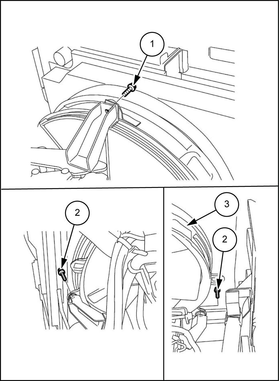
Use a wrench remove the bolts (1) , and then remove the fan guard (2)
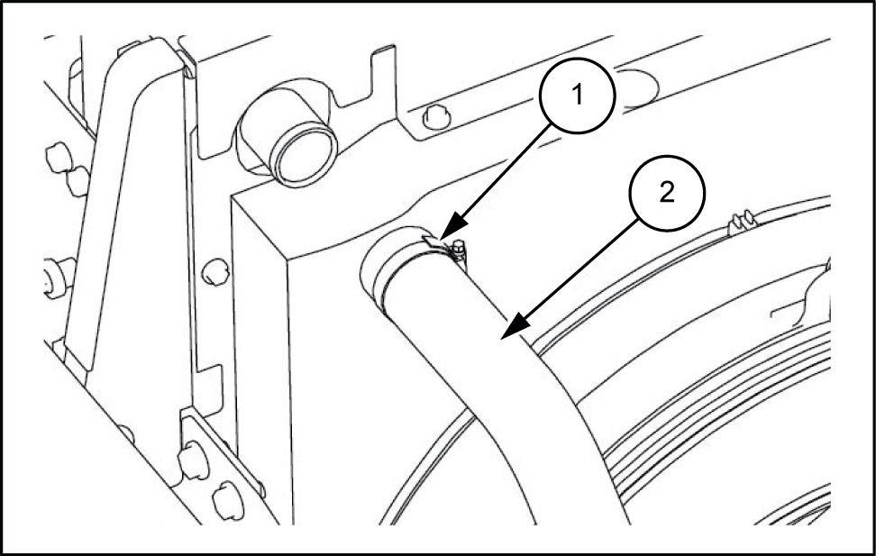
Use a wrench [ 7 ] loosen the hose band (1) the radiator , and then remove the upper hose (2)
LPIL12CX00144BB 1
LPIL12CX00145AB 2
SMIL13CEX1230AB 3
10.1 [10.001] /
47843013 21/05/2015
Use a wrench [ 7 ] loosen the hose band (1) the radiator , and then remove the lower hose (2)
• Attach caps each location the radiator and the hose prevent invasion water , dust, and
• Completely drain coolant before removing the tor SMIL13CEX1231AB
Use a wrench [ ] loosen the line bolts (1) 2 and then remove the pipings (2) and (3) from the compressor
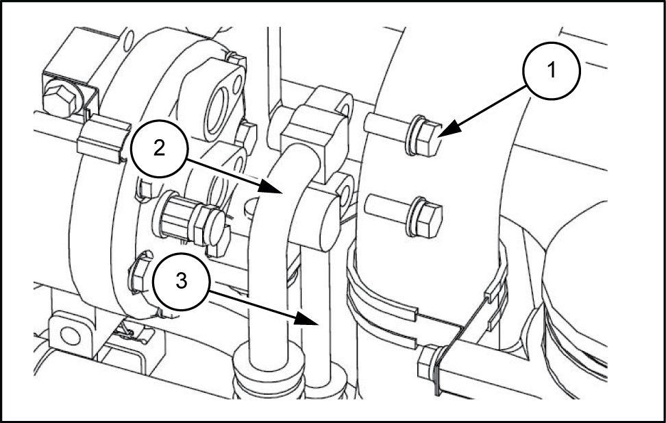
• Make sure remove the piping (2) low pressure (suction side) side
• Attach caps and plugs each location the pressor and piping order prevent invasion ter , dust and Line (discharge side) SMIL13CEX1232AB
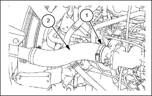
Use a wrench [ 8 ] loosen the hose band (1) the intercooler , and then remove the hose (2)
• Attach caps each location the piping and the hose prevent invasion water , dust and SMIL13CEX1233AB
Prepare a waste oil can (1)
• Drain the engine oil before removing the engine oil hose. SMIL13CEX1235AB
Engine - Engine and crankcase
4
5
6
7 47843013 21/05/2015 10.1 [10.001] /
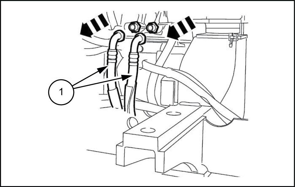
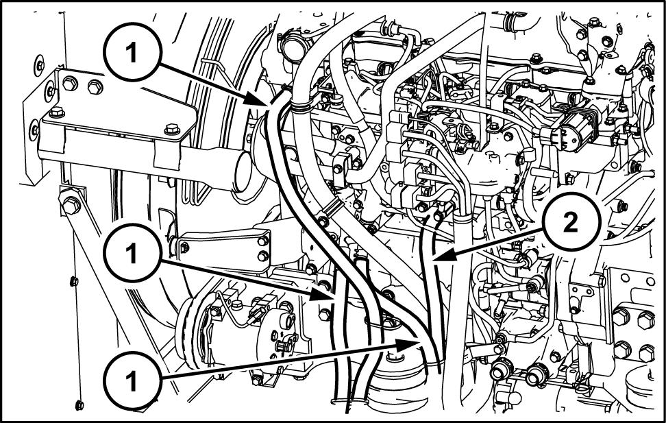
Use a wrench [ ] remove the 2 engine oil remote hoses (1)
• Apply marking each location the engine and the hoses match connections assembling.
• Attach caps and plugs each location the engine and the hoses prevent invasion water , dust and
• W ash each location the engine and the hoses blowing parts cleaner prevent adhering dirt connections and not damage SMIL13CEX1236AB
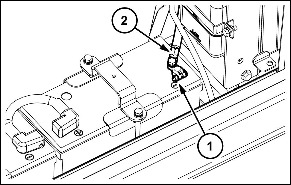
1 Remove the nut (1) with a wrench [ ] remove the battery cable (2) for minus
• Secure the terminal and harness order prevent them from touching the frame other parts when they have been protect them with a rubber cap other cap prevent SMIL14CEX5664AB
Use a wrench [ 8 ] remove the nut (1) , and then disconnect the wiring (2) from the starter motor
SMIL13CEX1238AB
Use a wrench [ ] remove the nut (1) , and then disconnect the wiring (2) from the starter motor
Engine
Engine -
and crankcase
8
9
1 1 47843013 21/05/2015 10.1 [10.001] /
SMIL13CEX1239AB
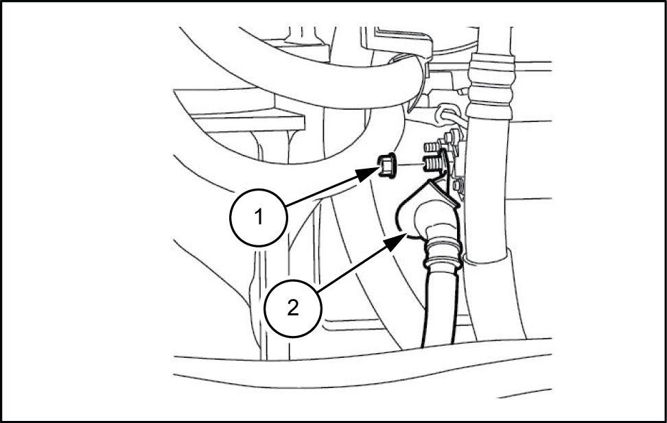
14. Remove the hose band (1) , and then remove the fuel hose (2)
• Attach caps and plugs the engine and the hoses prevent invasion water , dust and dirt.
SMIL13CEX1240AB
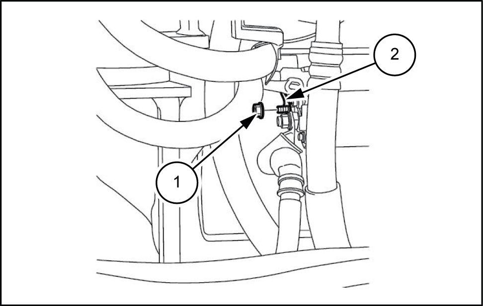
15. Remove the hose band (1) , and then remove the fuel hose (2)
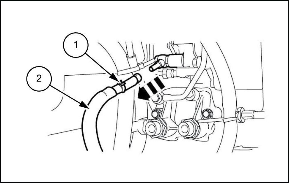
• Attach caps and plugs the engine and the hoses prevent invasion water , dust and
SMIL13CEX1241AB
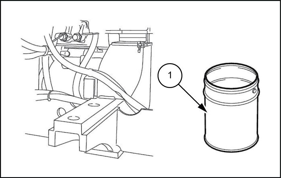
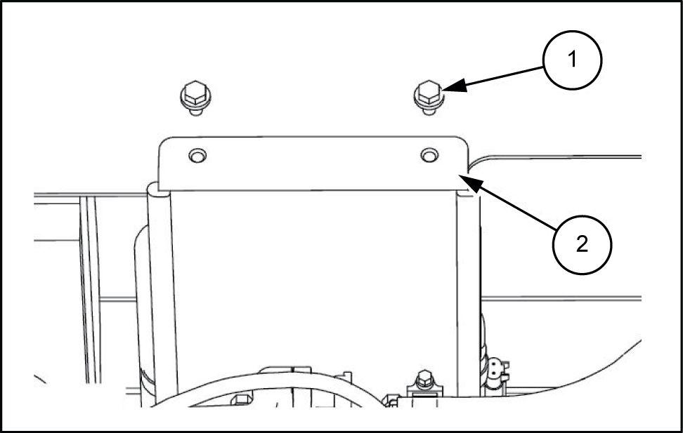
Use a wrench [ ] remove the 2 bolts (1) , and then remove the connector bracket (2)
SMIL13CEX1242AB
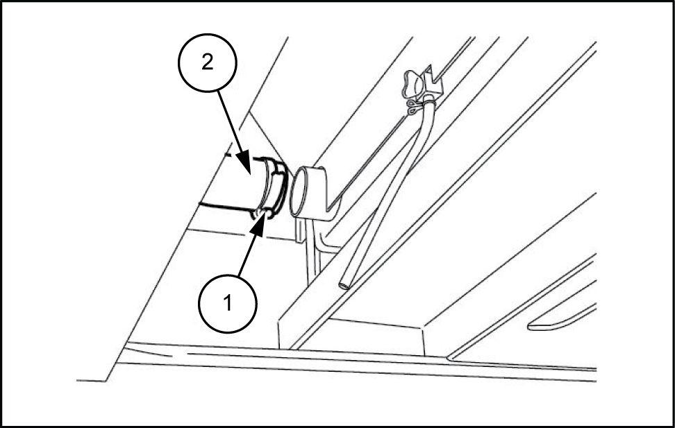
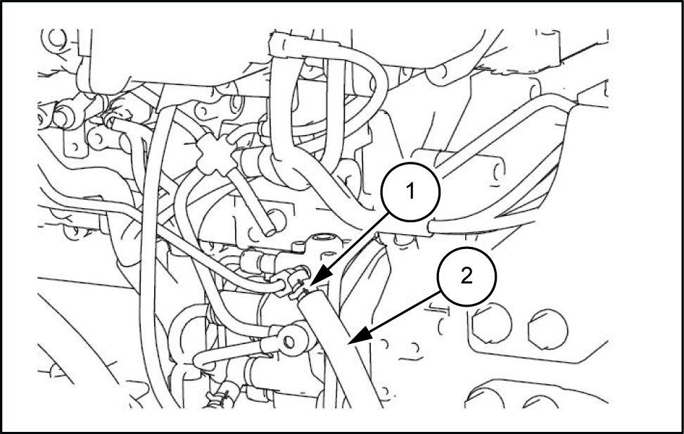
Use a wrench [ ] remove the hose band (1) from the and then remove the connectors (2)
• W rap the disconnected connectors with a plastic sheet after bundle
SMIL13CEX1243AB
Engine - Engine and crankcase
47843013 21/05/2015 10.1 [10.001] /
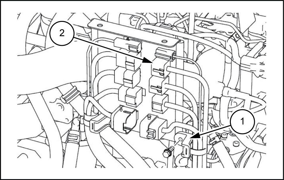
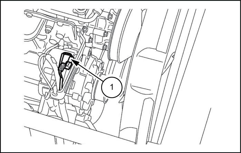
Loosen the hose band disconnect the three heater hoses (1)
Loosen the hose band disconnect the fuel hose (2) .
• Attach caps and plugs the engine and the hoses prevent invasion water , dust and
SMIL14CEX5665AB
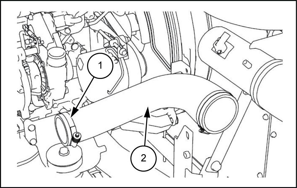
19. Use a wrench [ 9.5 ] loosen the hose band (1) , and then remove the air hose (2)
• Attach caps the piping and the hose vent invasion water , dust and
SMIL13CEX1248AB
Remove the connectors (1) from the alternator
SMIL13CEX1249AB
Use a wrench [ ] remove the nut (1) , and then remove the wiring (2) from the alternator

SMIL13CEX1250AB
Engine - Engine and crankcase
47843013 21/05/2015 10.1 [10.001] /
Engine - Engine and crankcase
SMIL14CEX5666AB
22. Remove the six nuts (1) with a wrench [ ] remove the muf fler (2)
47843013 21/05/2015 10.1 [10.001] /
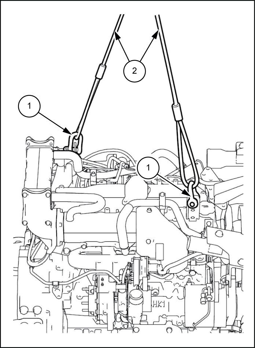
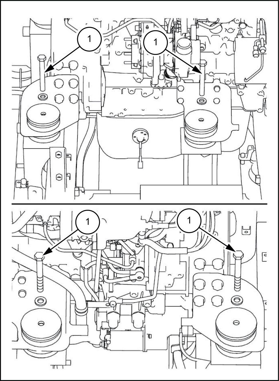
23. Attach the two shackles (1) and then secure the gine main unit with a wire rope (2) and a lifting
SMIL13CEX1252BB
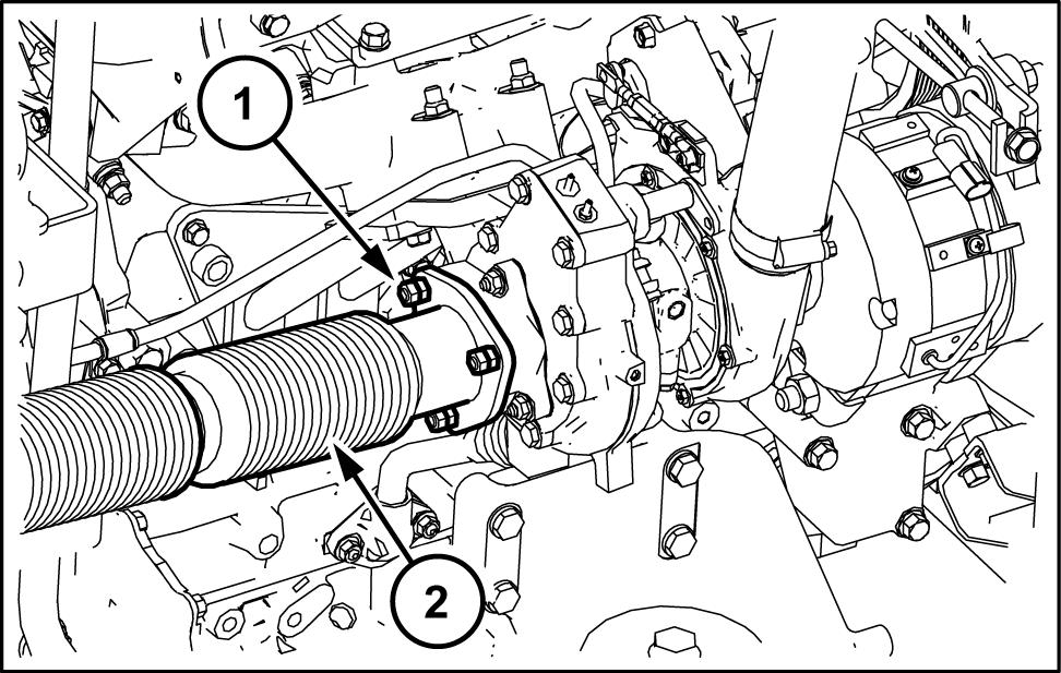
24. Use a box wrench [ ] remove the 4 bolts (1) from the
SMIL13CEX1253BB
Lift the engine main unit with a wire rope (1) and a lifting Make sure that you have a safe and then settle the engine a wood plank other block.
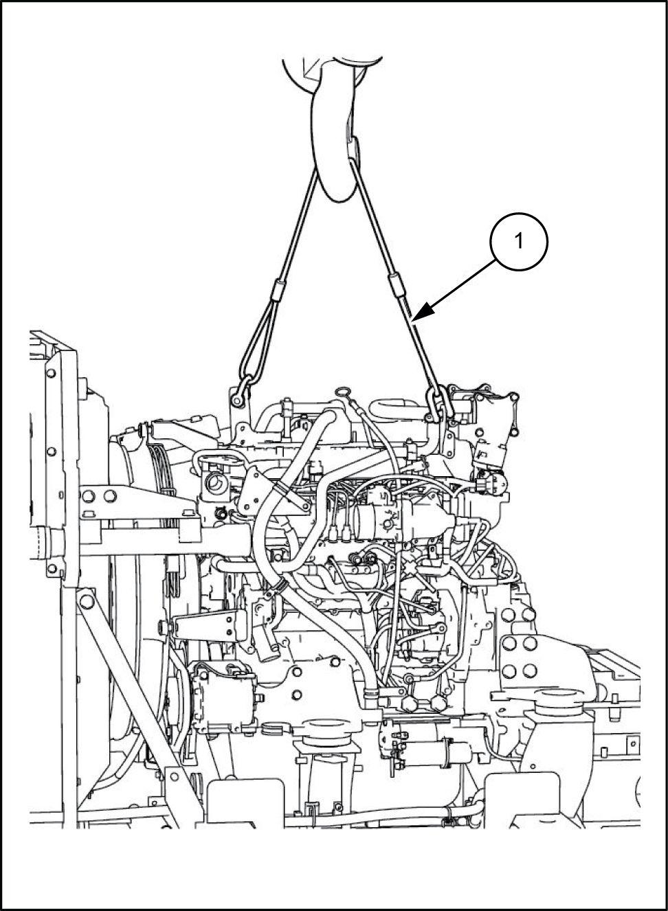
SMIL13CEX1254BB
Engine - Engine and crankcase
47843013 21/05/2015 10.1 [10.001] /
Engine - Engine and crankcase
Engine - Install
T o install the perform the reverse the removal procedure.
After installing the resupply coolant and engine perform fuel line air and perform filling for the air - conditioner
For see the individual explanations for each procedure.
Run the engine - load idling and check for any ter oil
Attach the hydraulic and For see the individual explanations for each
47843013 21/05/2015 10.1 [10.001] /
Engine - Engine and crankcase
Engine - Check - Engine oil
W ARNING
Burn hazard! not handle any service fluid (engine coolant, engine oil, hydraulic oil, etc.) temperatures that exceed (120 °F). Allow fluids cool before proceeding. Failure comply could result death serious injury
NOTICE: The engine should a horizontal position.
NOTICE: W ait least 5 min before starting the engine and after stopping the
Engine oil inspection
Remove the oil level gauge from the oil level gauge guide
NOTE: W ipe off the engine oil remaining the oil level
Install the oil level gauge the oil level gauge guide
Remove the oil level gauge from the oil level gauge guide
Inspect the engine
NOTE: Check the engine oil remaining the oil level gauge inspect the engine oil level.
Upper limit
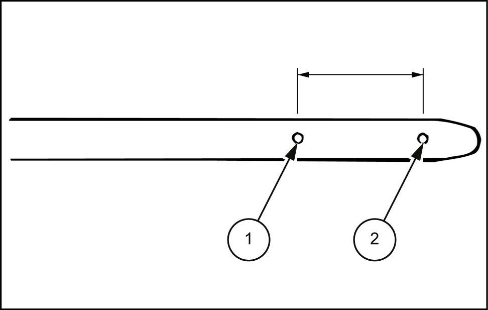
Lower limit
NOTE: the oil level under the lower add engine Replace the engine oil engine oil dirty
W0330B
SMIL14CEX3221AB 1 47843013 21/05/2015 10.1 [10.001] /
Suggest:
If the above button click is invalid.
Please download this document first, and then click the above link to download the complete manual.
Thank you so much for reading

Engine - T est - Engine oil
Sampling engine oil
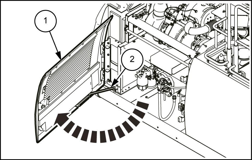
Open the side door (1) . At this make sure apply the lock (2)
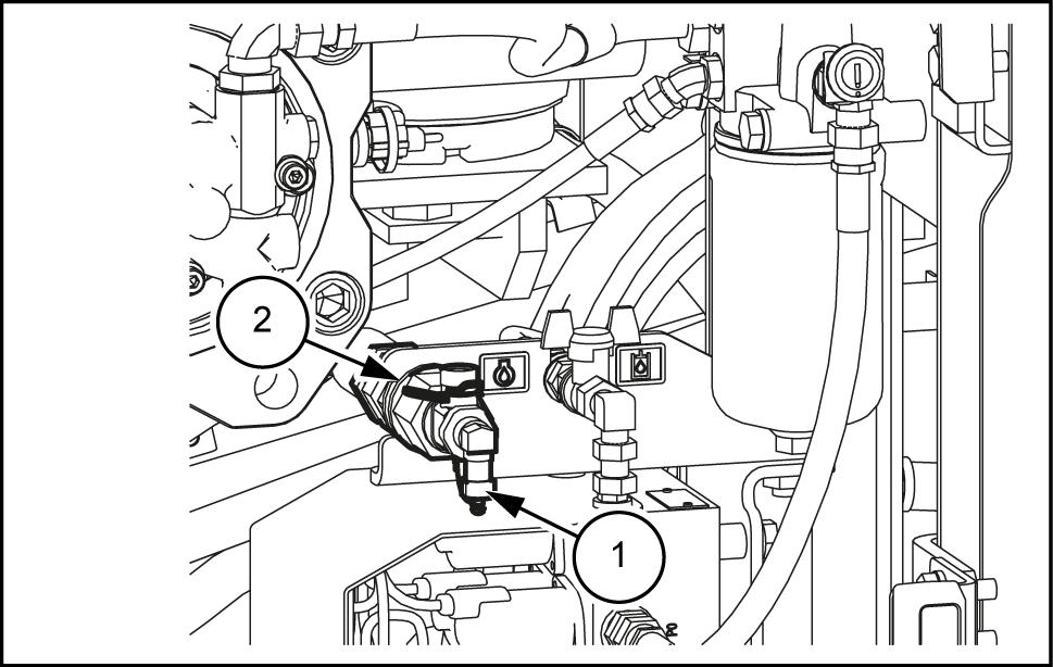
Place a sampling container under the sampling port (1)
Open the valve (2) drain a proper amount
Close the valve (2) check that there leakage. necessary , add the same amount oil the drained
Engine - Engine and crankcase
1
SMIL14CEX1 174AB
SMIL14CEX1 175AB 2 47843013 21/05/2015 10.1 [10.001] /