
Profile:
EXC, EW210D [GB]
Engine, identification
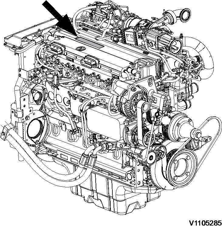
Identification plate
The engine model, serial number and performance data are stamped on an identification plate which is attached on the cylinder head cover. The engine model designation and serial number must be indicated when ordering spare parts.

[GB]
Component locations
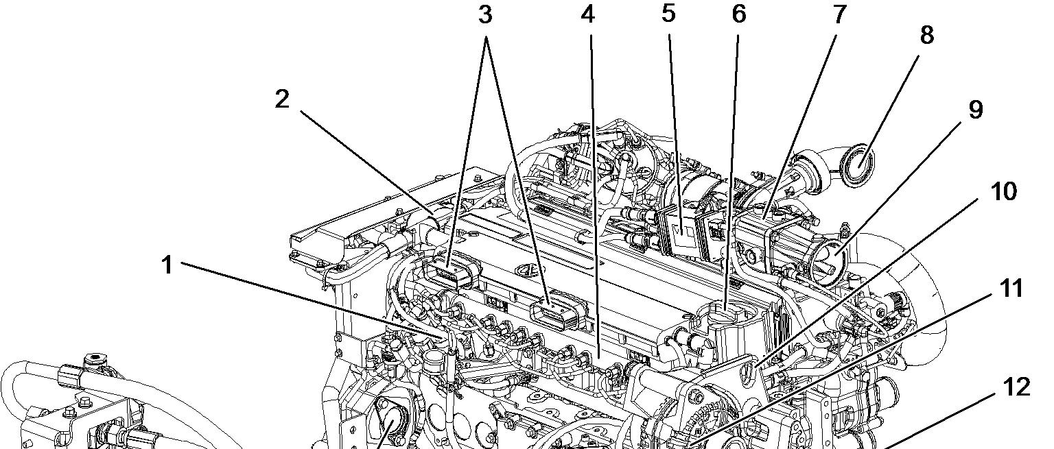
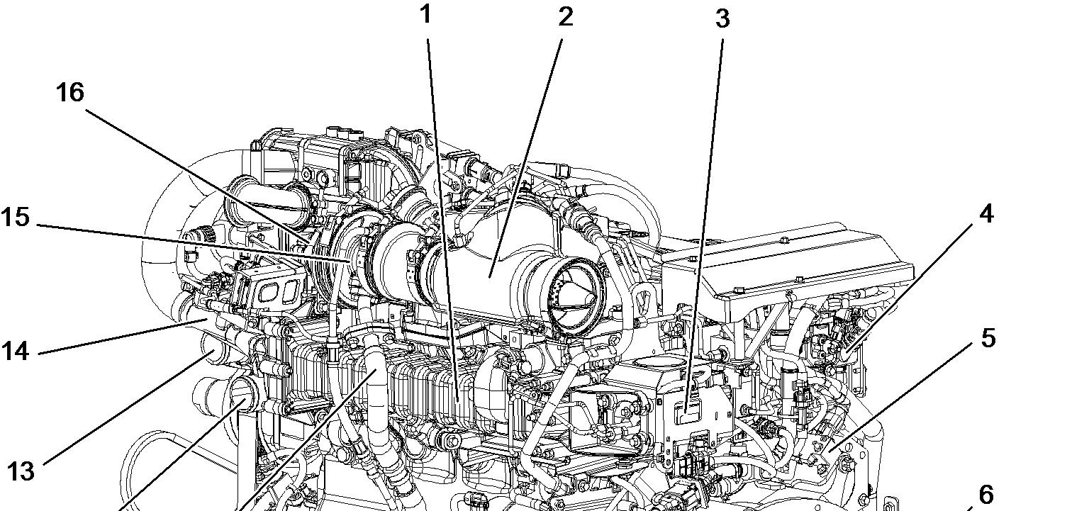
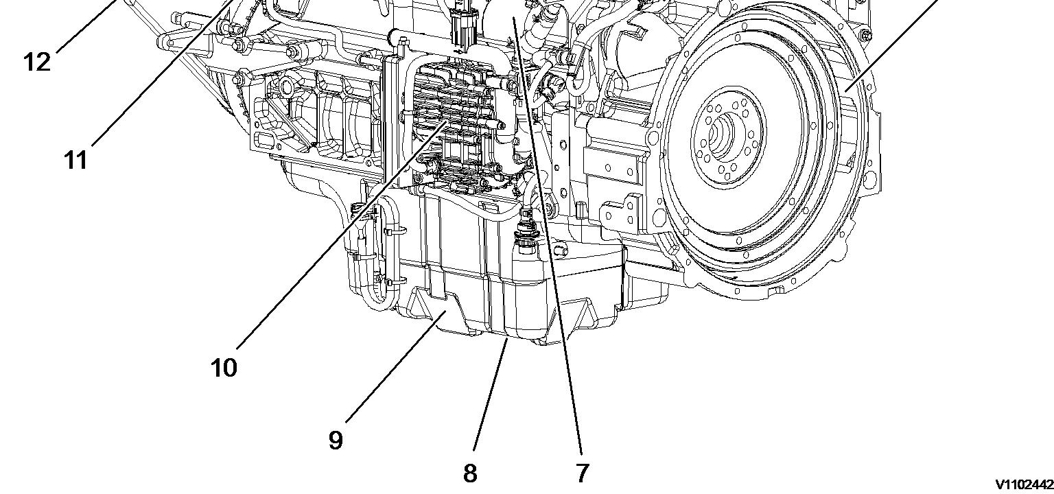
The following figures show the position of a number of components on engine D6H.

Profile: EXC, EW210D [GB]
Component location, sensors
The following figures show the position of sensors and electric components on the engine D6H.
 Figure 1
View pump side
Figure 1
View pump side
Components view pumps side Name Description
1 Spark plugs FX1031 Fuel temperature and pressure sensor before MV 1 +2
HE2502 Glow plug MA2508 Fuel metering valve MV1
SE2513 NOx sensor MA2509 Fuel metering valve MV2
SE2519 DPF differential pressure sensor MA2512 Shut-off valve
SE2521 Exhaust gas temperature sensor before DOC CU2501 Glow plug control unit
SE2522 Exhaust gas temperature sensor after DOC CU2503 Spark plug control unit
SE2523 Fuel pressure sensor after MV1 MO2505 EGR actuator
SE2524 Fuel pressure sensor after MV2
SE2525 Burner exhaust temperature sensor
SE2526 Exhaust gas pressure sensor
Components front side
Name Description
FX1007 SE2507/SE2508
SE2203
SE2301
SE2309
Boost air pressure and temperature sensor
Name
SE2606
Engine oil pressure sensor SE2703
Fuel feed pressure sensor
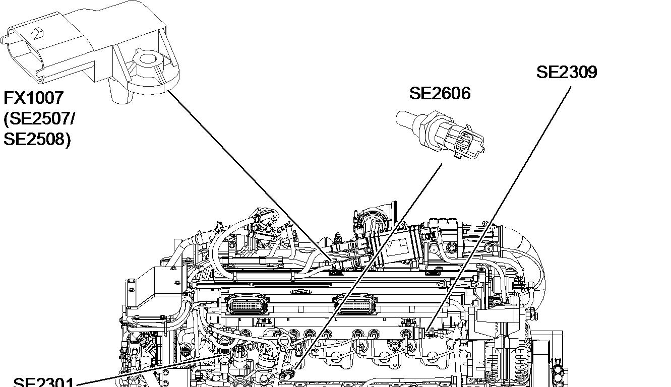
Common rail fuel pressure
SE2707
Description
Engine coolant temperature sensor
Engine speed sensor, camshaft
Engine speed sensor, crankshaft second
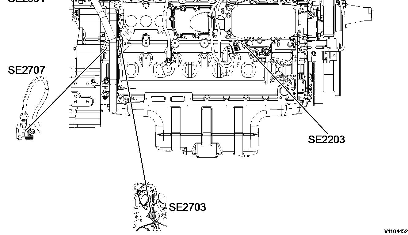 Figure 2
View front side
Figure 2
View front side

Components front side
Name
FX1006
SE2202/SE2205
SE2512
SE2515
SE2516
SE2520
Description
Name
Engine oil temperature and level sensor SE2532
Charge air temperature cooler SE2701
EGR differential pressure sensor MA2510
Description
Air pump mass flow sensor
Engine speed, crankshaft first
Purge air valve (PAV)
EGR temperature sensor MO2502 Air pump motor
Air pump pressure sensor
Document Title: Function Group: Information Type: Date: Valves, adjusting 214 Service Information 2014/5/4 0
Profile:
EXC, EW210D [GB]
Valves, adjusting
Op nbr 214-012
9998681 Rotation tool
885812 Timing tool
WARNING
Risk of burns - stop the diesel engine and allow it to cool down before starting any work.
1. Place the machine in service position B, see 091 Service positions
2. Turn OFF the battery disconnect switch.
Valve cover, removing
3. Remove the valve cover, see 214 Valve cover, removing NOTE!
For valve adjusting it is not necessary to remove the valve cover gasket!
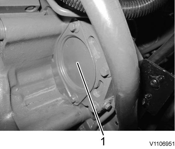
4. Remove the cover (1) in order to apply the special tool.
Figure 1
Cover
Setting the valve overlap for cylinder 1
5. Install the rotation tool (1). Special tool: 9998681 Rotation tool

Rotating tool
6. Turn the crankshaft using the rotation tool (1) until the valve overlap of cylinder 1 is reached.
7. Set the valve overlap for cylinder 1.
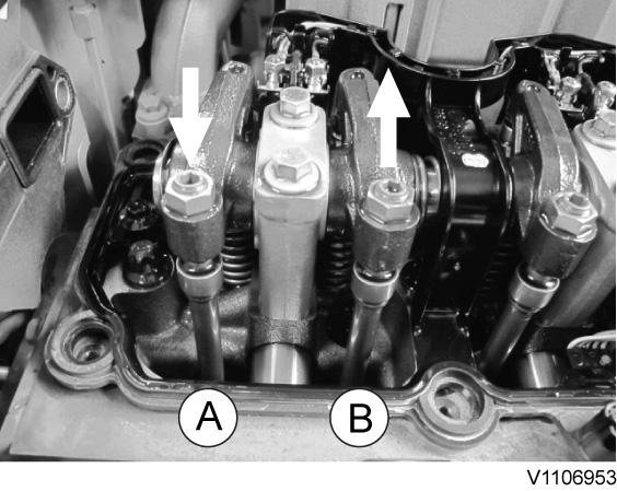
The valve overlap for a cylinder is reached when the outlet valve is about to close and the inlet valve is about to open. It should not be possible to rotate any push rods by hand for the cylinder in this position.
A Outlet valve
B Inlet valve
8. The black marked valves in the setting schematic can be adjusted. Set the clearance for inlet and outlet valves by following the steps:
Setting the inlet valve clearance Setting the outlet valve clearance
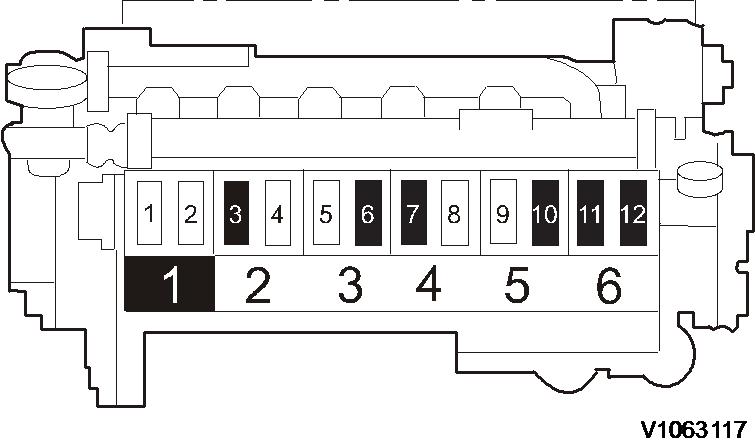
Figure 2 Figure 3 Overlapping Figure 4 Setting schematic overlap cylinder 1 (located on the flywheel side)6, 10, 12 are inlet valves
3, 7, 11 are outlet valves
Setting the inlet valve clearance
9. Set inlet valve clearance according to the setting schematic for overlapped cylinder.
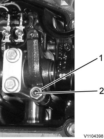
Loosen lock nut (1) counterclockwise. Turn setting screw (2) clockwise by hand until it stops.
NOTE!
The rocker arm (4) must touch the thrust washer (3) of the spring cap (5).
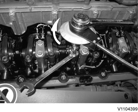

Set special tool (885812 Timing tool) on the setting screw with a suitable socket. Fix magnet of the special tool to the cylinder head. Set the angle gauge clockwise to “0”
Turn the setting screw 75° counterclockwise
Figure 5 Rocker arm inlet valve Figure 6 Set to zero
Hold the setting screw to prevent it turning and tighten the lock nut clockwise, tightening torque: 20 Nm (14.8 lbf ft)
Setting the outlet valve clearance
10. Set the outlet valve clearance according to the setting schematic for overlapped cylinder.
Loosen lock nut (1) counterclockwise.
Turn setting screw (2) clockwise by hand until it stops.
NOTE!
The rocker arm must touch the thrust washer of the spring cap (arrow).
Set special tool (885812 Timing tool) on the setting screw with a suitable socket. Fix magnet of special tool to the cylinder head. Set the angel gauge clockwise to “0”
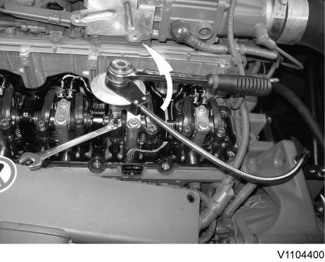 Figure 7
Set clearance
Figure 8
Rocker arm outlet valve
Figure 7
Set clearance
Figure 8
Rocker arm outlet valve
Figure 9
Set zero
Turn the setting screw 120° counterclockwise
Set clearance
Hold the setting screw to prevent it turning and tighten the lock nut clockwise, tightening torque 20 Nm (14.8 lbf ft)
Set the valve overlap for cylinder 6
11. Turn the crankshaft using the rotation tool (1) clockwise one turn (360°). NOTE!
Make a check mark on the belt pulley for better control.
12. Set the valve overlap for cylinder 6.
The valve overlap for a cylinder is reached when the outlet valve is about to close and the inlet valve is about to open. It should not be possible to rotate any push rods by hand for the cylinder in this position.
Overlapping
A Outlet valve
B Inlet valve
13. The black marked valves in the setting schematic can be adjusted.

Figure 13
Setting schematic overlap cylinder 6
2, 4, 8 are inlet valves
1, 5, 9 are outlet valves
14. Set the clearance for inlet and outlet valves by following again the steps:
Setting the inlet valve clearance
Setting the outlet valve clearance
NOTE!
Use schematic for overlapping cylinder 6.
Valve cover, installing
15. Clean all sealing surfaces.
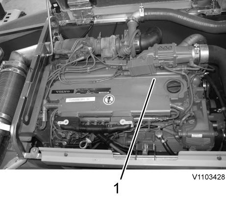
16. Remove the rotating tool and install the cover (1).
Figure 1217. Install the valve cover, see 214 Valve cover, installing
18. After the completion of the work, start the engine and check for leaks and operating condition.
Document Title:
Valve cover, removing 214
Profile: EXC, EW210D [GB]
Valve cover, removing
Op nbr 214-037
WARNING
Risk of burns - stop the diesel engine and allow it to cool down before starting any work.
1. Place the machine in a service position, see 091 Service positions
2. Turn OFF the battery disconnect switch.
3. Open the engine hood.
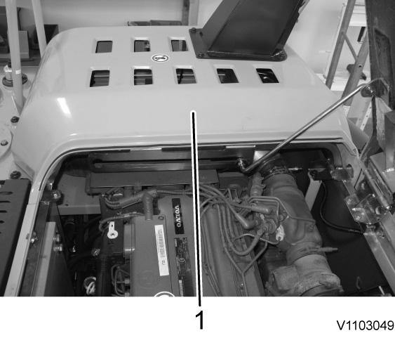
4. Remove the DPF (Diesel particulate filter) hood (1).
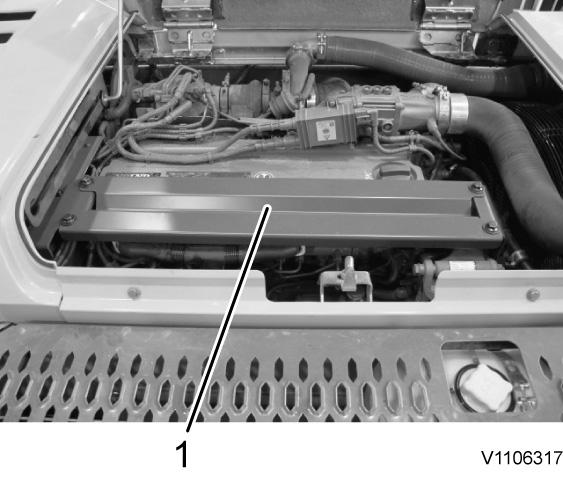
5. Remove the protection cover (1) above the engine.
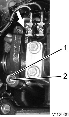
6. Remove bracket (1) and cover (2) above crankcase ventilation.
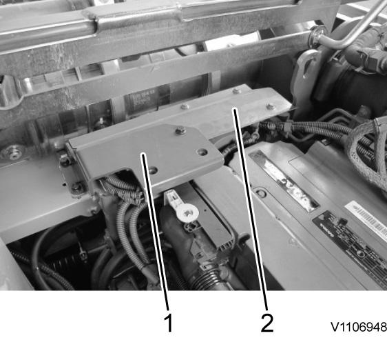
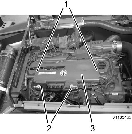
 Figure 3 Bracket and cover
7. Disconnect main connectors (2), remove screws (1) and move aside the cable duct (3).
Figure 4 Cable duct
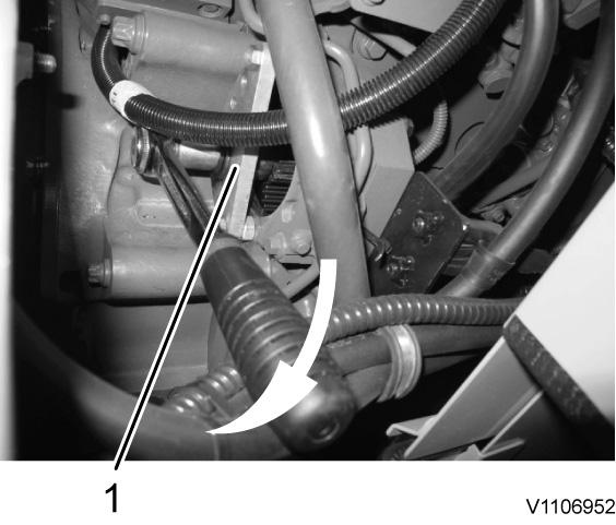
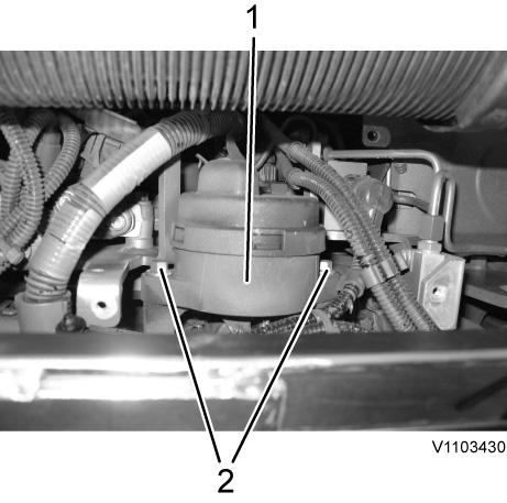
8. Disconnect connectors (1).
Figure 5 Connectors
9. Disconnect connector (3), remove screws (1) and lay aside the spark plug ECU (2).
Figure 3 Bracket and cover
7. Disconnect main connectors (2), remove screws (1) and move aside the cable duct (3).
Figure 4 Cable duct
8. Disconnect connectors (1).
Figure 5 Connectors
9. Disconnect connector (3), remove screws (1) and lay aside the spark plug ECU (2).
Suggest:
If the above button click is invalid.
Please download this document first, and then click the above link to download the complete manual.
Thank you so much for reading

11. NOTICE
Carefully clean around the valve cover to prevent dirt and debris from getting into the engine while work is in progress.
Remove screws (2) and loosen the crankcase ventilation housing (1). NOTE!
Take care of the O-ring between the housing and the cover!
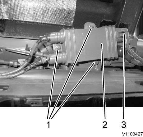 Figure 6
Spark plug ECU
10. Pull off the cover strip (1). It is only fixed with clips.
Figure 7
Cover strip
Figure 6
Spark plug ECU
10. Pull off the cover strip (1). It is only fixed with clips.
Figure 7
Cover strip