
Document Title: Function Group: Information Type: Date:
Engine, description 200 Service Information 2014/3/8 0
Profile:
CWL, L20B [GB]
Engine, description
Machines with SN 1700001 – / – 1703000 are fitted with the VOLVO D3D engine. The engine is a four-cylinder, four-stroke, in-line diesel engine with direct injection and oil/air cooling.
Machines fromSN 1703001 – are fitted with the VOLVO D3.6D engine. he engine is a four-cylinder, four-stroke, in-line diesel engine with direct injection, oil/air cooling and externally controlled exhaust gas recirculation (EGR).

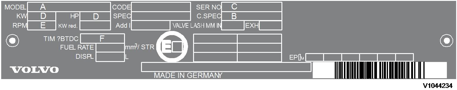
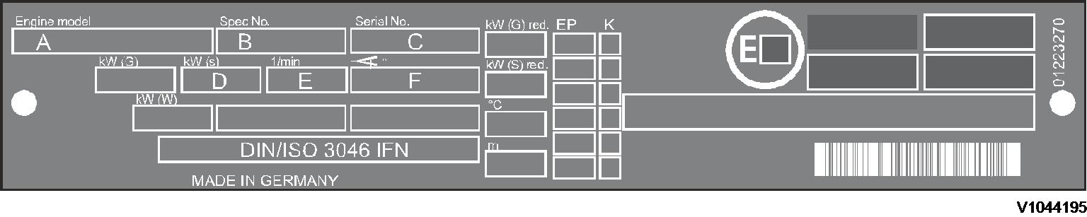
The engine data plate specifies model, engine number and power data. The engine number is also stamped into the crankcase. Model and engine number must be specified when ordering spare parts. The direction of rotation is found on the flywheel, anticlockwise. Firing order: 1-3-4-2 (cylinder no. 1 on the flywheel side).
IMPORTANT! Adjustments to the regulator may only be performed by trained staff in an authorized central repair workshop.
Capacity
Rated speed
Timing setting
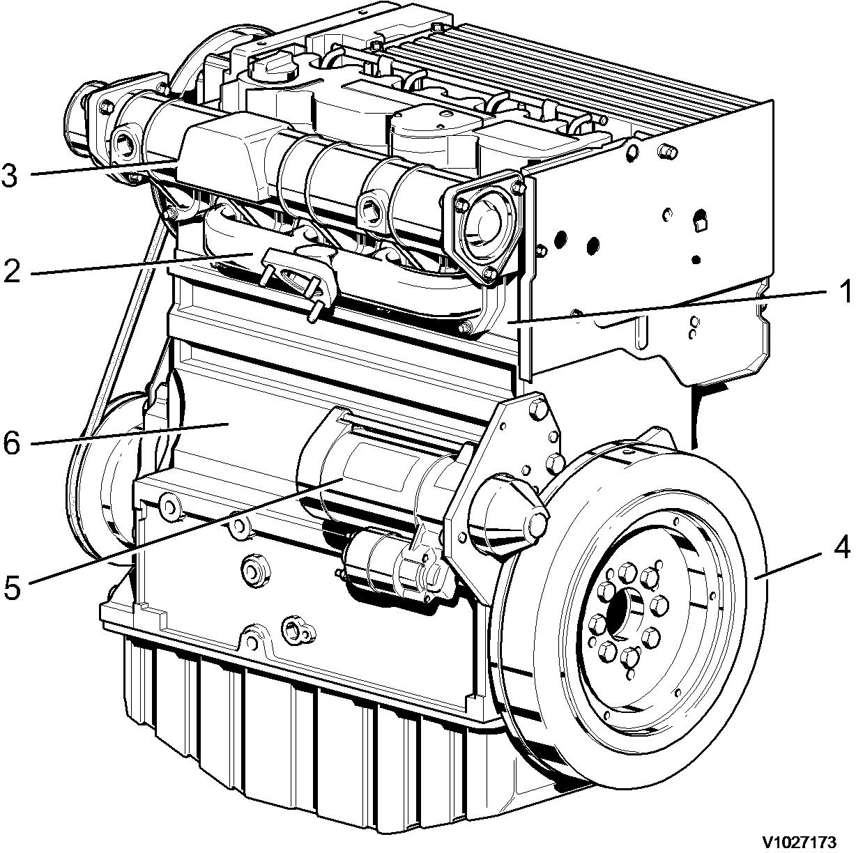
Components, servicing view
Components, servicing view
Oil filler port (valve cover)
Air inlet pipe
Fan with integrated alternator

V-rib belt
Engine stop solenoid
Gear housing cover, timing belt cover
V-belt roller, crankshaft
Oil sump
Start/stop lever
Engine speed adjustment
Oil dipstick
Oil filler pipe
Fuel pump
Fuel filter
Oil filter
Cooling air baffle
Injection pumps
Oil cooler
Components, exhaust view
Figure 3 1. 2.Exhaust gas recirculation (EGR)
In order to comply with emission limits, the engine is equipped with an externally controlled exhaust gas recirculation system, which directs some of the exhaust gas back into the combustion air. The oxygen content of this exhaust gas is low, which serves to lower the peak combustion temperature, thereby reducing generation of nitrogen oxides (NO ).
The exhaust gas required for recirculation is directed from the cylinders via a line system and travels through the EGR valve via the exhaust induction port directly into the inlet ports of the cylinder head, where it is re-aspirated by the engine.
The EGR valve is active when the load is between 0 and 75%. If the load is greater than 75%, the EGR valve remains closed to prevent oxygen deficiency through high smoke formation.
The EGR valve is controlled via a control rod displacement sensor. An LED on the control rod displacement sensor indicates the status of the exhaust gas recirculation system. The LED is lit when the system is active.
The control rod displacement sensor and EGR valve are supplied power via connector x40 (stop solenoid Y6).
Oil from rocker arm lubrication is used to cool the EGR valve. This oil travels back to the oil sump via the oil return system.
Figure 4 Components, exhaust view 1. 2. 3. 4. 5. 6. Cylinder head Exhaust manifold Air inlet pipe Flywheel Starter CrankcaseExternally controlled exhaust gas recirculation
EGR valve Exhaust induction port Exhaust supply Lubrication oil from cooling taken from rocker arm lubrication Lubrication oil return to oil sump Electrical cable for control rod displacement sensor Control rod displacement sensor
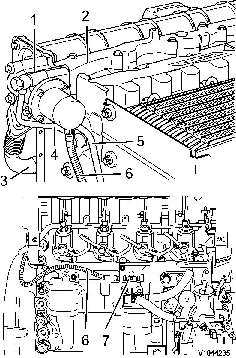 Figure 5
1. 2. 3. 4. 5. 6. 7.
Figure 5
1. 2. 3. 4. 5. 6. 7.
Document
Profile:
CWL, L20B [GB]
Engine, removing
Op nbr 210-070
1. Place the machine in service position.
2. Switch off the battery disconnect switch and disconnect the positive battery terminal.
WARNING
The work involves handling heavy components - failure to stay alert may result in severe crushing injuries.
3. Open the engine hood and unscrew the fixing bolts.
4. Lift off the engine hood and place it on a suitable surface.


5. Remove the air flow guide plate (1).
6. Disconnect the pin plug connection of the tail lights.
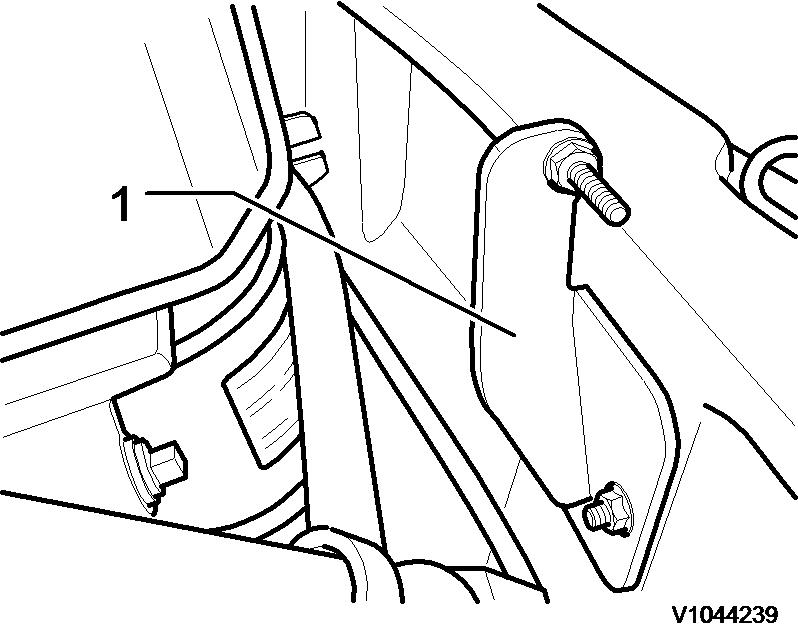
7. Detach the engine hood catch (1) at the counterweight.
8. Attach a lifting device (E-tool) to the counterweight and suspend it from the crane using suitable hoisting equipment.
NOTE!
Lower the counterweight onto a suitable surface.
NOTE! Mark supply and return.
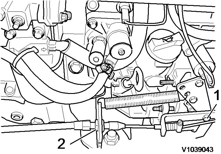
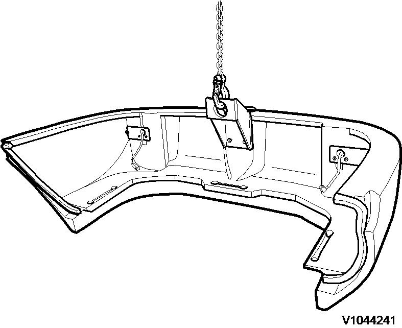 Figure 5
11. Detach the throttle cable from the engine. Unscrew the bracket (1) and slacken the jam nuts (2).
Figure 6
12. Remove heater connections (1) and (2) and seal with plugs.
Figure 7
13. Remove air duct cover
Figure 5
11. Detach the throttle cable from the engine. Unscrew the bracket (1) and slacken the jam nuts (2).
Figure 6
12. Remove heater connections (1) and (2) and seal with plugs.
Figure 7
13. Remove air duct cover
NOTICE
When a hose has been disconnected, plug both the hose and the connection immediately. The hoses should be marked for correct connection.
15. Undo the hose clamp (1) and detach the fuel hose (2) from the fuel pump.

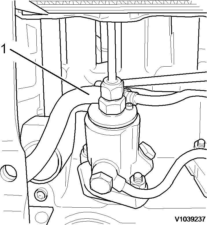
 Figure 8
14. Undo the hose clamp with clamping tongs and detach the fuel return hose (1).
Figure 9
Figure 10
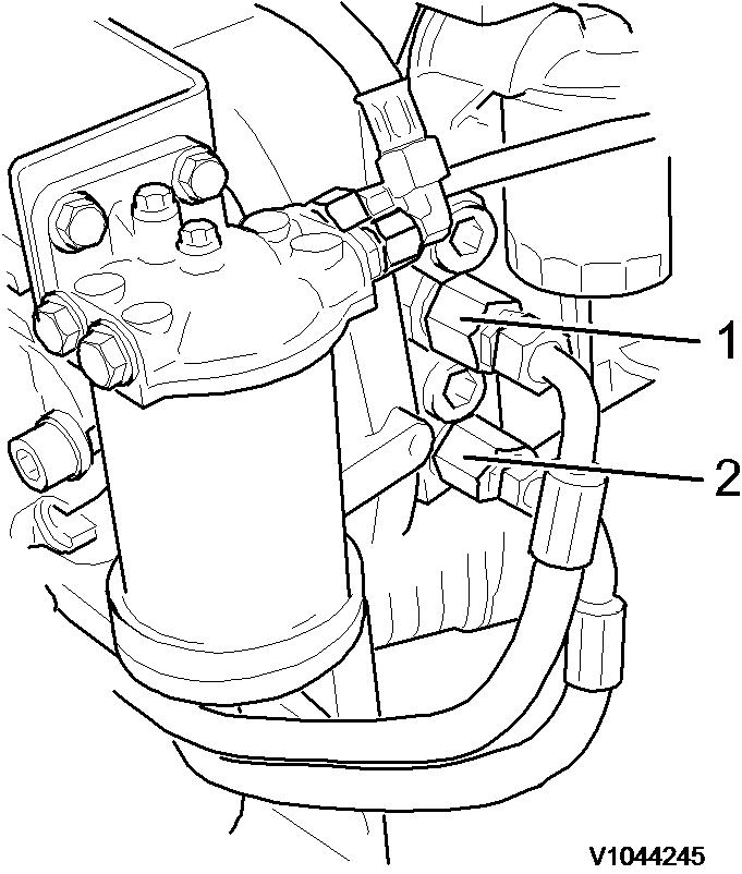
16. Unscrew the bolt (1) at the connection flange and remove the bracket (2) with the fuel filter/water separator assembly.
Figure 8
14. Undo the hose clamp with clamping tongs and detach the fuel return hose (1).
Figure 9
Figure 10
16. Unscrew the bolt (1) at the connection flange and remove the bracket (2) with the fuel filter/water separator assembly.


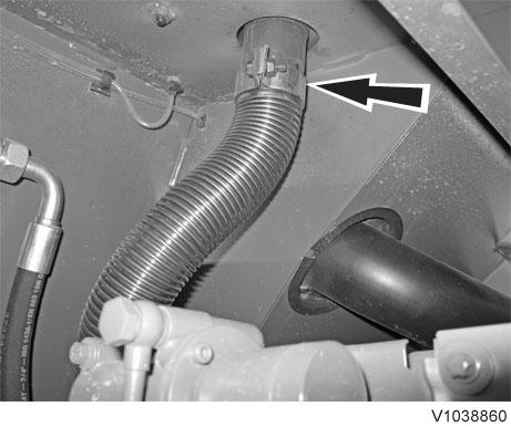 Figure 11
17. Unscrew the remaining bolts at the connection flange.
Figure 12
18. Suspend the hydraulic variable displacement pump from a crane using suitable hoisting equipment and pull it out of the connection housing. Support the hydraulic variable displacement pump and put it aside.
19. Remove the flexi exhaust pipe from the silencer.
Figure 13
20. Disconnect the connection cable (1) from the air filter control switch.
Figure 11
17. Unscrew the remaining bolts at the connection flange.
Figure 12
18. Suspend the hydraulic variable displacement pump from a crane using suitable hoisting equipment and pull it out of the connection housing. Support the hydraulic variable displacement pump and put it aside.
19. Remove the flexi exhaust pipe from the silencer.
Figure 13
20. Disconnect the connection cable (1) from the air filter control switch.
21. Release clamp (2) on air filter intake hose and pull hose (3) off air inlet pipe.
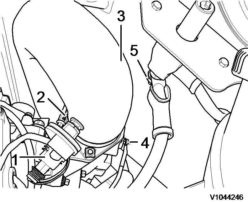
22. Unscrew the glow plug connection cable (4).
23. Unscrew the ground connection (5) from the battery disconnect switch.
24. Disconnect electrical pin plug connection X24 (fuel tank sensor) and X26 (engine connection).
25. Undo clamp (1) and remove cable tie.
26. Remove ground connection (2) at engine block.
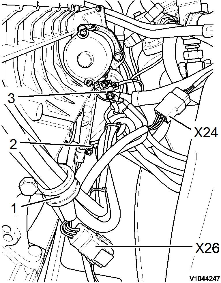
27. Disconnect charging current line (B+) to starter (3).
28. Remove engine bracket fixing bolts at frame.
Figure 14 Figure 15
 Figure 16
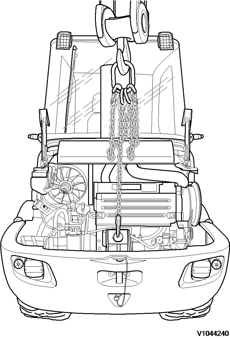
29. Fasten a lifting device (E-tool) to the engine and suspend from the crane.
Figure 17
30. Slowly out the engine and place it on a suitable surface.
Figure 16
29. Fasten a lifting device (E-tool) to the engine and suspend from the crane.
Figure 17
30. Slowly out the engine and place it on a suitable surface.
Document
Profile: CWL, L20B [GB]
Engine, installing
Op nbr 210-072
WARNING
The work involves handling heavy components - failure to stay alert may result in severe crushing injuries.
1. Fasten a lifting device (E-tool) to the engine and suspend from the crane.
2. Slowly lower the engine into the engine bay and position on the engine mounts.
NOTICE
Make sure that no hoses or cables are trapped.
3. Tighten the engine bracket fixing bolts to the frame. Tightening torque 200 Nm (148 lbf ft)
4. Unhook the lifting device and unscrew from the engine.
5. Connect electrical pin plug connection X24 (fuel tank sensor) and X26 (engine connection).
6. Install ground connection (2) at engine block.
7. Attach charging current line (B+) to the starter (3).
8. Screw in clamp (1) and fit cable tie.
9. Attach intake hose (3) to the air inlet pipe and fasten with the clamp (2).
Figure 2 Figure 311.
13.
Figure 4
10. Connect the connection cable (1) to the air filter control switch.
Screw on the glow plug connection cable (4).
12. Screw the ground connection (5) onto the battery disconnect switch.
Fit the flexi exhaust pipe to the silencer.
Figure 5
14. Suspend the hydraulic variable displacement pump from a crane using suitable hoisting equipment and position it on the connection housing.
Figure 6
15. Screw in the connection flange bolt (1) and fit the bracket (2) with the fuel filter/water separator assembly. Tighten
20.
NOTE!
Observe supply and return markings.
NOTE!
one turn.
Depress the accelerator pedal all the way and check whether the engine speed adjustment level rests against the adjuster screw.
Figure 10
19. Fit heater connections (1) and (2).
Figure 11
Attach throttle cable to the engine. Fasten the bracket (1) and slacken approximately
Tighten the jam nuts (2).
Figure 12
21. Suspend the counterweight from a crane using suitable hoisting equipment and position it on the rear frame plate.
Suggest:
If the above button click is invalid.
Please download this document first, and then click the above link to download the complete manual.
Thank you so much for reading

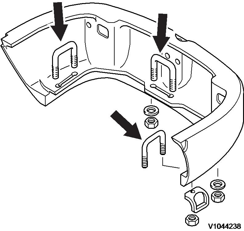
22. Fit the counterweight retaining bracket (arrows) and tighten the fixing nuts to 210 Nm (155 lbf ft)
23. Connect the pin plug connection of the tail lights.
24. Detach the lifting device (E-tool) from the counterweight and refit the engine hood catch (1).
Figure 13
Figure 14