
CONDENSED SERVICE DATA
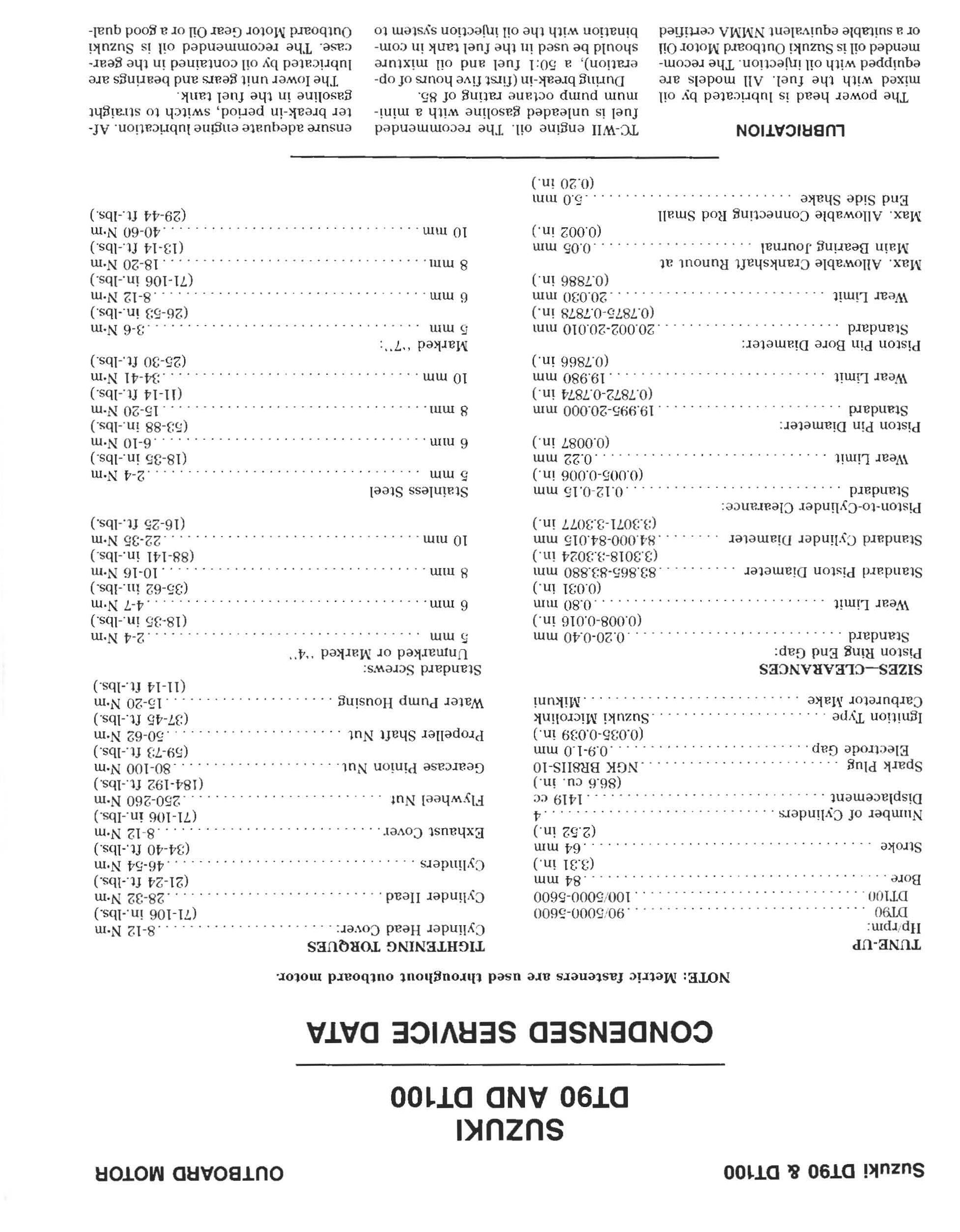
NOTE: Metric fasteners nre used throughout outboard motor.
TUNE-UP
IIp /rpm : DT90 90/ 50 00-5600 DTlOO 100/ 5000-5600
Bore 84 mm
Stroke (:3.31 in . ) 64 mm (2.52 in .) 4
TIGHTENING TORQUES
Cy lind e r Head Cover: 8- 12 N'm
Cylinder Head
Cylinders
Exhaust Cover
(iI-106 in -Ibs.) 28-32 N'm (21- 2 4 ft.-Ibs.) 46-54 N'm (34-40 ft.·lbs.)
Spark Plug Electrode Gap.
Ignition Type Carbureto r Make
Number of Cylinders . Displa ce ment 1419 cc (86.6 c u in .) NGK BRSIIS-IO .O.!H.O mm (0.035 ·0.0:39 in .) Suzuki Microlink Mikuni
SIZES-CLEARANCES
Piston Ring End Gap: Standard ....
Wear Limit
Standard Piston Diameter
0.20-0.40 mm (0.008-0.016 in .) ... . . ............ . 0.80 mm (0.031 in ) 83.865·8:3.880 mm (3 3018-:3.:3024 in .)
Standard Cylinder Diam e ter 84.00 0-84.015 mm (:3 :3071-3.3077 in.)
Piston·to-Cylinder Clearanc e: Standard. . . . .. .. ... . ... 0.12 0.15 mm
Wear Limit
Piston Pin Diameter: Standard
Wea r Limit
Piston Pin Bore Diam e t e r: Standard Wea r Limit
Max. Allowable Crankshaft Runout at Main Bearing Journal
Max. Allowable Connecting Rod Small End Side Shake
(0.005-0.006 in ) 0.22 mm (0.0087 in.)
19 .9% -20.000 mm (0 .7872-0.7874 in .) 19.980 mm (0.7866 in.)
20 002·20.010 mm (0 787,5 0.7878 in.) 20.030 mm (0.7886 in.)
0.05 mm (0.002 in.) 5.0 mm (0.20 in . )
Flywhe e l Nut
LUBRICATION
The power head is lubri cated by oil mixed with the fu e l. All models are equipped with oil il\jection . The recommended oil is Suzuki Outboard Motor Oil or a suitable equival e nt NMMA certified
8 12 N'm (71-106 in .- Ibs. ) .250-260 N'm (184-192 ft. lbs )
Gearcase Pinion Nut. 80-100 N'm
Propeller Shaft Nut (59-7:3 fUbs.) . .50-62 N'm
Wat e r Pump Housing ......... .. . . . (37-45 ft.-Ibs.) 15-20 N'm (11-14 ft.-Ibs.)
Standard Screws: Unmarked or Marked " 4" !'imm 2 4 N'm (18 :35 in .-Ibs.) 6 mm 4-7N ·m (:35-6 2 in.-Ibs.) .... .... 10·16 N'm ( 88-14 1 in. Ibs . ) 8111111 •
10 mm 22-35 N'm (16-25 ft. lb s.)
Stainless Steel 5 mm
6 nun 8 mill
.2- 4 N'm (18-35 in.-Ibs ) .6 -10 N'm (5:3-88 in .- lbs ) 15-20 N'm (11-14 fUbs.) :34 41 N'm (25-30 ft.-lbs.) 10 mm Marked "7": 5 mm 6 mm 8 mill
10 mm
3-6 N'm (26-5:3 in -Ibs.) 8-12 N'm (71-106 in .- Ibs .) 18-20 N'm (13·14 fUbs.) .40 -6 0 N'm (29-44 ft .- Ibs )
TC-WII engine oil. The recommend e d fuel is unleaded gasoline with a minimum pump oclane rating of 85.
During break-in (first fiv e hours of ope ration) , a 50; 1 fuel and oil mixture should be use d in the fuel tank in combination with the oil il\jection system to
e nsure adequate engine lubri cation. Af· ter break in period, switch to straight gasoline in the fu e l tank
The lower unit gears and bearings are lubricated by oil co ntained in the gearcase. The recommended oil is Suzuki Outboard Motor Gear Oil or a good qual-
Suzuki DT90 & DT100 OUTBOARD MOTOR
••.
.. ... .
..... .. . . . . . . . . . . . .. . . . . .. .
....
.. ... . .
ity SAE flO hypoid gear lubricalll. Gearcase capacity is mL (l8.fl fl. oz.). The gearca.-;e oil should be changed after the first to hours of operation and every toO hours thereafter.
FUEL SYSTEM
CARBURETOR. BW:l6-24 carburetors are used on Model 011)0 and Mikuni \3W40-:32 carburetor.; are us ed on Model DTIOO. Two carburetor.; are us ed on all models. l{efer to Fig. SZ18 1 for exploded view.
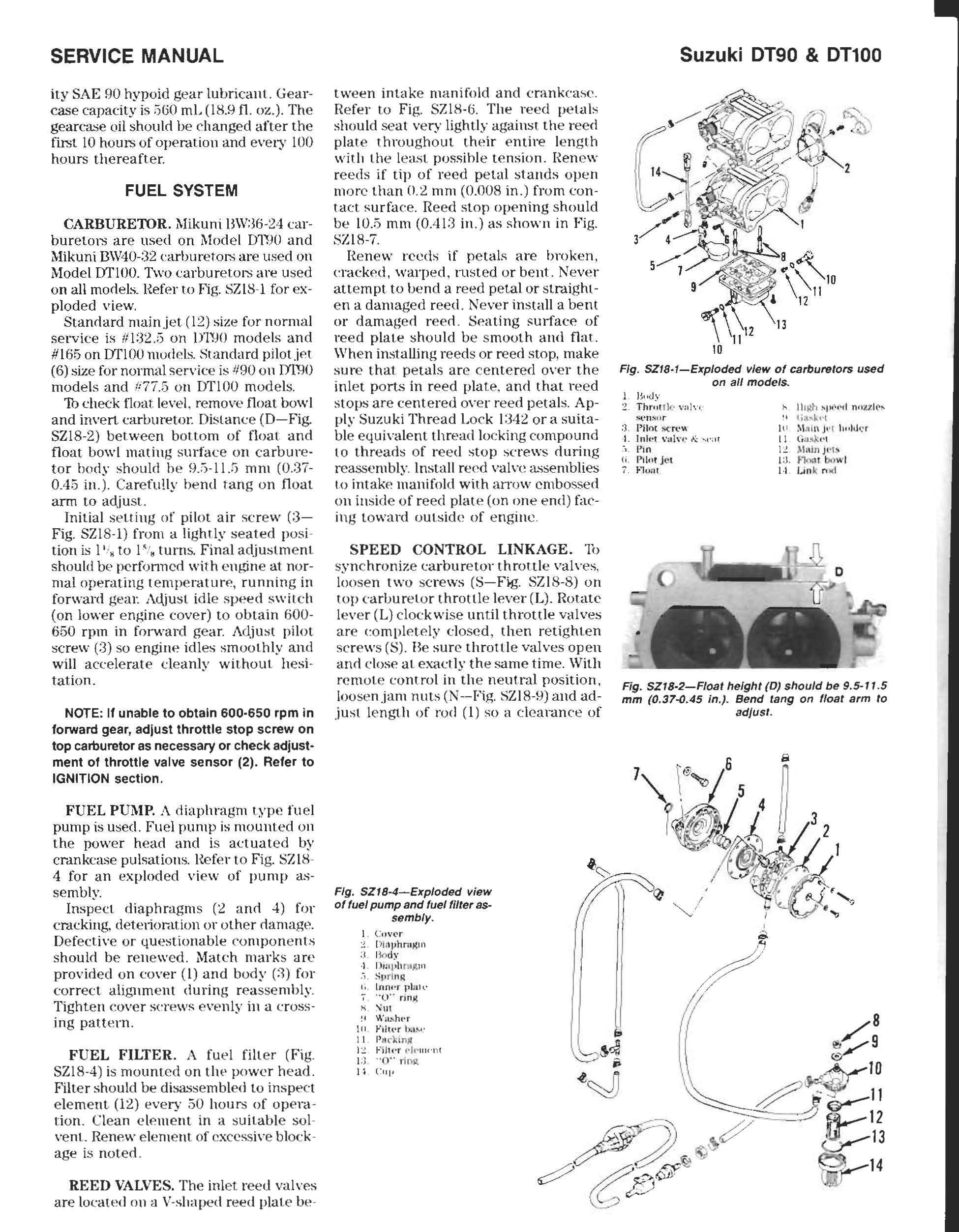
Standard main jet (12) size for normal service is 111:32.;5 on D1WJ models and #165 on DTlOO nlOdds. Standard pilotjN (6) size for normal service is 1190 on m1l0 models and !i77.5 on m'lOO models.
Th check float le\'e1, re mo\'e float bowl and invert carburetol: Distanc e (D- Fig. SZI8-2) between bottom of float: and float bowl mating s urfac e on carbure· tor body should be mm (0.:37 0.45 in.). Carefully bend rang on float arm to adj us t.
Initial selling of pilot air screw (3Fig. SZI8-1) from a lightly seated posi tion is I' , to I". turn s. Final adjustment should be pcrfonncd with engine at normal operating temp e rature, running in forward gear. Adjust idl e speed s wit c h (on lower engine cover) to obtain 600650 rpm in forward gear. Adjust pilot screw (3) so engine idles smoothly and will accelerate cleanly without hesi tation.
NOTE: II unabte to obtain 600·650 rpm in lorward gear, adjust throttle stop screw on top carburetor as necessary or check adjust· ment 01 throttle valve sensor (2). ReIer to IGNITION section.
FUEL PUMP, A diaphragm type fu e l pump is usee!. Fuel pump is mounted on the power head and is actuated by crankcase pulsations. I{e fer to Fig. SZI8 4 for an exploded vi e w of pump assembly.
Inspect diaphragms (2 and 4) for cracking, de telioration or ot h er damage. Defective or questionable co mpon e nts should b e re n e wed. Mat c h marks are provided on cover (I) and body (:1) for correct alignment during reasse mbly Tighten cover s cre ws e venly in a c r ossing patt e rn.
FUEL FILTER. A fu e l fill e r (Fig. SZI8-4) is mounted on th power h ead. Filter should be di!;&is e mble d to inspect element (12) every 50 hours of op e ra tion . Clean clement in a suitable so l \·enl. Re n e w e lem e nt of excess iv e block age is note d
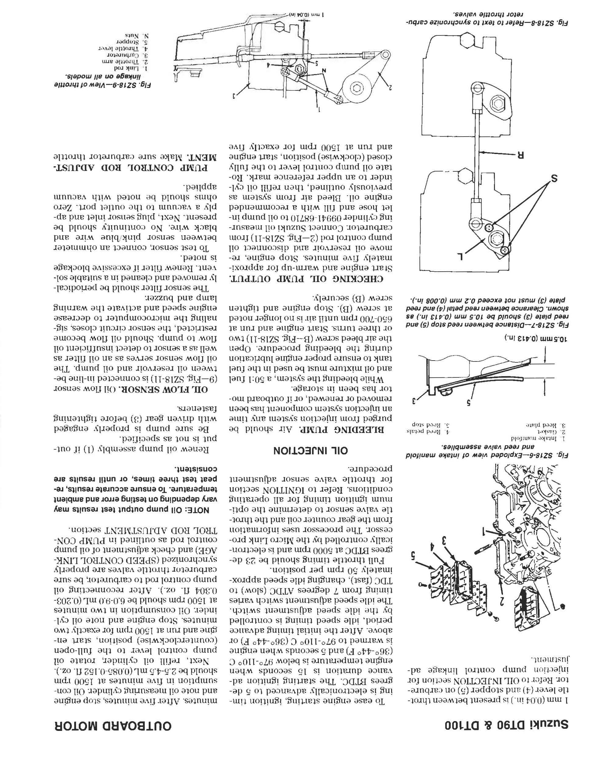
REED VALVES. Th e inl et reed valves are loca ted on a V-shaped reed plat e be
tween int,lke manifold and cranke-ase. Re fer to Fig SZI8·5. The reed pe tals should seat very lightly against th e reed plat e throughout their e ntire length with the le,L<;t possihle t ension. Ren e w reeds if tip of reed p eta l stands open m o re than 0.2 mm (O.OOS in .) from conta ct surface. Reed stop opening should be 10.5 mm (0.413 in .) as shown in Fig. SZIS-7.
[{ e n e w re eds if petals are broken, eracked, warp ed, rll ste d or b e nt. Ne ver attempt to bend a reed petal or straighte n a damaged r eed. Ne ver install a bent or damaged reed. Seating s1ll1-ac:e of r eed plate should be s mooth and flat. Wh e n installing reeds or reed stop, make sure that petals are ce nter ed over the inl e t ports in reed plate , anti that reed stops are centered over re e d petals. Apply Suzuki Thread Lo c k 1:342 ora suitable eq uival ent thread lo cki ng compound to threads o f re e d stop screws during reasse mbly Install reed vain! assemblies i.o intake manifold with alTow embossed on inside of r eed plate (on one end) facing toward outside of engine
SPEED CONTROL LINKAGE. '11> sy n c hroniz e carburetor throttle valves. loo se n two screws (S-Fjg. SZI8-8) on top earburetor throttle lever (L). Rotate lever (L) cloc kwi se until throttle v<llves are eompletely closed , then retighten screws (S). Be sure throttle valves open and dose at exactly the same time. With remote control in the neutral position, loos e n jam nuts (N-Fig. SZIS-9) and adjust le ngt h of rod (I) so a c:icarance of
Fig. SZI8-1-Exploded view of carburetors used on all modelS.
Hood\' Thr;, n k · \ ';iln: S('tl .$lI f" :) Pilot
1. \ '.1\\ 1' 1\: ".' :11 (i rUt" Jet I. Jo'U;'l1
k "!lui " !I lif\ '\;. "1 ill :\\ 1111\ j " t 1I"ld';: r II G iJ..s)W I I i. ) l:dnJl'b I:;. fi n ,-u bll w l , .1. I.in 'c ro d
Fig. SZIS-4-Exploded view of fuel pump and fuel filter assembly.
I C,I\' l'r
W".,ht'r
F,hl'r b..",-
SERVICE MANUAL
:! ; j ! \-)dy 1. U'iiJ ,h F1. Ijl. 1I1 j SI} l'"i lllol, ,; 11)111''' " 0" rinj( K
\(I
1 1 P t1ck in " I :! FIJkr .-, I. IIwnl I :l 0" r loil. If C III' Suzuki 0190 & 01100
Fig. SZIS·2-Floal height (D) should be 9.5· I 1 5 mm (0.37-0.45 in.). Bend lang on float arm to ad/usl.
I mm (OJH in.) is pres e nt betwe e n throttl e lever an d stopper (5) on carburetor. Refe r 10 OIL IN.JECTION se ction for iqjeLti o n pump control linkage adjustm ent.
To ease engin e stalting , ignition liming is electronically advanced to 5 degre es BTDC. The starting ignition advan ce duration is 15 seconds when engine temperature is below 87°-1100 C (:36°-44° F) and 5 seconds when enb'in e is warm ed to 97°-110° C (3(j0-44° F) o r above. After th e initial timing advan ce period. idle spe e d timing is controlled by thp. idle speed adju st ment s witch. The idle spe ed acljustment switc h varies timing from 7 degrees ATDC (slow) to TD C (fast) , c hanging idle speed approximately 50 rpm per position
Full throttle timing should be 2:3 degrees BTDC at 5000 rpm and is electronically controlled by the Micro Link processor. The processor uses information from the gear co unter co il and the throttle valve sensor to det e rmine the optimum ignition timing for all operating co nditions. Hefer t o IGNITION section for throttle ,·alve sensor acljustment procedure.
OUTBOARD MOTOR
minutes. Aft e r five minutes. slop engine and note oil mea.,uring cylinder. Oil consumption in fiv e minutes at 1500 rpm should be 2.5-4.5 mL (OJ)H5 0.152 fl. oz.)
Next. refill oil cylinder, rotate oil pump control lever to the full-open (counterclo ck wise) po s ition , start engine and run at 1500 rpm for exactly two minutes. Stop engine and not e oil cyl imler. Oil consumption in two minutes at 1500 rpm should be (j.O-8.0 mL (0.2030.:304 fl. oz.). After reconnecting oil pump co ntrol rod to carburetOl; b e s ure carburetor throttle valves are prop e rly syn c hronized (SPEED CO NTHOL LiNKAGE) and c h ec k acljustment of oil pump control rod as outlined in PUMP CONTROL ROD ADJUSTMENT sec tion.
NOTE : 011 pump output test results may vary depending on testing error and ambient temperature. To ensure accurate results, repeat test three times, or until results are consistent.
Fig. SZI8-6-Exploded view of intake manifold and reed valve Bssemblles.
1 InUtk c rn :inlfold
2. CiiI.S).;.'-l :3 Hced
<1 H('l'd p(-l:,lb :; H('('d s t(Jp
OIL INJECTION
BLEEDING PUMP. Air should be purged from ir\jection system any time an irljection system co mpon en t has been removed or renewed , or if outboard m otor has been in s torage
Renew o il pump assembly (I) if output is not as sp ec ified.
Be sure pump is prop e rly engaged with driven gear (:3) before tightening fasten e rs.
10.5mm (0.413 In.)
Fig. SZI8-7-Dls/Mce belween reed slap (5) and reed plale (3) should be 10.5 mm (0.413 In.) ss shown. CleafsnC6 between reed petal (4) Bnd reed plele (3) musl not exceed 0.2 mm (0.008 In.).
Whil e bleeding the system, a 50:1 fuel and oil mixture must be used in the fuel tank to ensure proper e ngine lubrication during the bleeding procedure. Open the air bleed screw (B-Fig. SZIH-Il) two or three turns. Start engine and run at MiO-700 rpm until air is no longer not ed at screw (n). Stop engine and tighten screw (il) securely.
CHECKING OIL PUMP OUTPUT. Start engine and warm-up for approximately fiv e minute s. Stop engine. r e move oil r ese rvoir and dis co nnect oil pump control rod (2-Fig. SZIS-Il) from carbureto!: Connect Suzuki oil mea s uring cylinder 08!J4HiH7!O to oil pump inlet h ose and fill with a recomm en ded engine oiL l3Ieed air from system as previously outlined, then refill oil cylinder to an upper r e ference mark. Hotate oil pump control lever t o the fully closed (clockwise) position, start engine and run at 1500 rpm for exactly five
OIL FLOW SENSOR. Oililow sensor (9 -Fig. SZIS-II) is co nnected in-line between oil reservoir and oil pump. The oil flow sensor serves as an oil filter as well a.g a sensor to detect insufficient oil flow to pump. Should oil flow be co me restri cted , th e sensor c irc uit clos es, signaling the microcomputer to decrea.,e engine spe ed and activate th e warning lamp and buzzer.
The sensor filter should be periodically remov e d and cleaned in a SUitable solvent. He new filt e r if exces si ve blo c kage is noted.
Tb t es t sensor. conne ct an ohmmeter between sensor pinklblue wire and black wire. No continuity should be present. Next. plug sensor inlet and apply a vacuum to the outl e t port. Zero ohms should be noted with vacuum applied.
PUMP CONTROL ROD ADJUSTMENT. Make sure carburetor throttle
Fig. SZI8-9- VIew ofthrottle linkage
Fig. SZ18-8-Refer to text to synchronize carburetor thronle valves.
Suzuki DT90 & 01100
1 mm ro.cw
on all models. I Link roo 1.. ThTOftl(' ann 3. Cu rhuret.or 4 Thro ttle 5. S(t) PrK'r S l\uu

Thank you very much for your reading. Please Click Here. Then Get COMPLETE MANUAL.NOWAITING NOTE: If there is no response to click on the link above, please download the PDF document first and then clickonit.
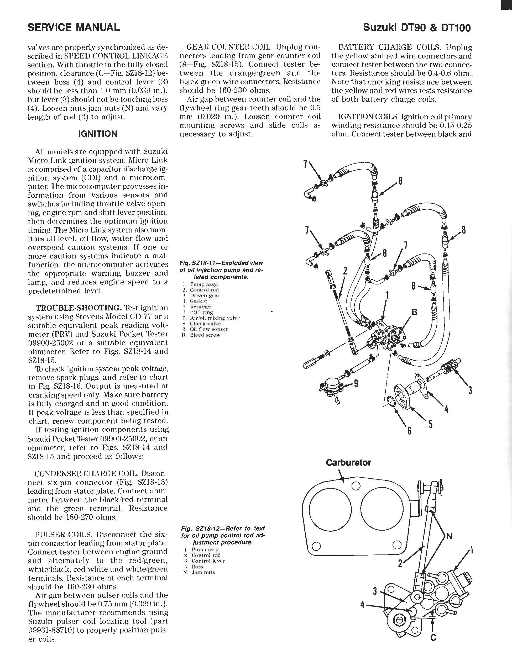
valves are properly synchronized as described in SPEED CONTROL LINKAGE section. With throttle in the fully closed position, clearance (C-Fig. SZIS-12) between boss (4) and control lever (3) should be less than 1.0 nlIn (0.0:,9 in.), but lever (3) should not be touching boss (4). Loosen nuts jam nuts (N) and vary length of rod (2) to adjust.
IGNITION
All models are equipped with Suzuki Micro Link ignition system. 1Ilicro Link is comprised of a capacitor discharge ignition system (CDl) and a microcomputer. The microcomputer processes information from various sensors and switches including throttle valve opening, engine rpm and shift lever position, then determines the optimum ignition timing. The ]llicro Link system also monitors oil level, oil flow, water flow and overs peed caution systems. If one or more eaution systems indicate a malfunction, the microcomputer activates the appropriate warning buzzer and lamp, and reduees engine speed to a predetermined level.
TROUBLE-SHOOTING. Test ignition system using Stevens 1I10dei C D-77 or a suitable equivalent peak reading voltmeter (PRV) and Suzuki Pocket Tester 09900-25002 or a suitable equivalent ohmmeter. Refer to Figs. SZIS-14 and SZIS-L3.
1b check ignition system peak voltage, remove spark plugs, and refer to chart in Fig. SZIS-16. Output is measured at cranking speed only. Make sure battery is fully charged and in good condition. If peak voltage is less than specified in chart, renew component being tested.
If testing ignition components using Suzuki Pocket '!ester 09900-25002, or an ohmmeter, refer to Figs. SZIS-14 and SZIS-15 and proceed as follows:
COl\DENSER ClIARGE COIL. Disconnect six-pin connector (Fig. SZIS-15) leading from stator plate. Connect ohmmeter between the black/red terminal and the green terminal. Resistance should be 180-270 ohms.
PULSER COILS. Disconnect the sixpin connector leading from stator plate. Connect tester between engine ground and alternately to the red/green, white/black, red/white and white/green terminals. Resistance at each terminal should be 160-230 ohms.
Air gap between pulser coils and the flywheel should he 0.7!; mm (0.029 in.). The manufacturer recommends using Suzuki pulser eoil IDeating tool (part 09931-88710) to properly position pulser coils.
GEAR COUNTER COIL. Unplug connectors leading from gear counter coil (8-Fig. SZIS-15). Connect tester between the orange/green and the black!green wire eonneetors. Resistance should be 160-230 ohms.
Air gap between counter coil and the flywheel ring gear teeth should be 0.5 mm (0.020 in.). Loosen counter coil mounting screws and slide coils as necessary to adjust.
BATTERY CHARGE COILS. Unplug the yellow and red wire connectors and connect tester between the two connectors. Resistance should be 0.4-0.6 ohm. Note that checking resistance between the yellow and red wires tests resistance of both battery charge coils.
IGNITION COILS. Ignition coil primary winding resistance should be 0.15-0.25 ohm. Connect tester between black and
Fig. SZI8-11-Exploded vIew of all Injection pump and related components.
p \nnp (';o m rol rod :1. DIi \' (' n "Wa r -1.
" 0" ri ng
A ir /n il niixln p; H Ch('(: k \' 1.Llv(' o. ()
L'I
Fig. SZI8·12-Refer to text for all pump control rod adJustment procedure.
P u mp i;L'\!iy C.o nlrol r od :3 G<Jn l TI1 1 it.'\'(,'r 1. &$:.1 ,J(, m nut s
SERVICE MANUAL
j[ fI( )w s(: nsq r
ll lt' l' d Ii (; n'
Suzuki OT90 & OT100
carburetor •