
Remove Steering Clutches

START BY:
a) remove brake hydraulic controls and actuating mechanisms
1. Drain the oil from the steering clutch case.

2. Remove plug (1) from the side of the steering clutch case.

NOTICE
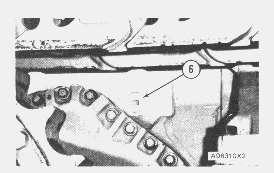
Remove all of the bolts (2) and (5) except for one on each side of the steering clutch. The machine must be moved forward or backward to remove all of the bolts.
3. Remove bolts (5) that hold the steering clutch to the steering clutch hub. Remove bolts (2) that hold the steering clutch to the flange through the opening in the bevel gear case from which plug (1) was removed. Use tool (A) to move the machine to turn the steering clutch to remove the bolts.
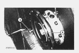
4. If so equipped, disconnect oil line (3) from fitting (4).


Install Steering Clutches


 5. Install two 3/8"-16 NC × 4 in. long bolts and nuts in the brake bands as shown. Fasten a hoist to the brake bands and remove the last two bolts that hold the steering clutch in position. Remove steering clutch (6) from the machine. The weight is 175 lb. (79 kg).
1. Install two 3/8"-16 NC × 4 in. long bolts in the brake bands and fasten a hoist as shown.
2. Put steering clutch (1) in position between the steering clutch hub and the flange. Install two bolts (2) and (3) to hold the steering clutch in position. Remove the hoist and bolts from the brake band.
3. Put 5P3931 Anti-Seize Compound on the threads of all the bolts. Install the bolts that hold the steering clutch in position. Tighten the bots to a torque of 200 ± 20 lb.ft (270 ± 25 N·m).
5. Install two 3/8"-16 NC × 4 in. long bolts and nuts in the brake bands as shown. Fasten a hoist to the brake bands and remove the last two bolts that hold the steering clutch in position. Remove steering clutch (6) from the machine. The weight is 175 lb. (79 kg).
1. Install two 3/8"-16 NC × 4 in. long bolts in the brake bands and fasten a hoist as shown.
2. Put steering clutch (1) in position between the steering clutch hub and the flange. Install two bolts (2) and (3) to hold the steering clutch in position. Remove the hoist and bolts from the brake band.
3. Put 5P3931 Anti-Seize Compound on the threads of all the bolts. Install the bolts that hold the steering clutch in position. Tighten the bots to a torque of 200 ± 20 lb.ft (270 ± 25 N·m).
NOTE: Use tool (A) or move the machine to install the bolts that hold the steering clutch in position.
4. If so equipped, connect oil line (4) to fitting (5).

5. Install plug (6) in the steering clutch case.
6. After the brake actuating mechanism is installed, fill the steering clutch case and bevel gear case with oil to the correct level. See MAINTENANCE GUIDE.
END BY:
a) install brake hydraulic controls and actuating mechanisms
Disassemble Steering Clutches
START BY:
a) remove steering clutches

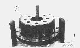
1. Put tool (B) over the stud of tool (A). Fasten a hoist and put steering clutch (1) in position on tool (A) and (B).


 2. Remove brake band (2) from the outer drum.
3. Install two 5/8"-11 NC forged eyebolts in the outer drum. Remove outer drum (3). The weight of the outer drum is 110 lb. (50 kg).
4. Install tooling (C) and nut (4) over the stud of tool (A). Put disc aligners (5) of tooling (A) in position.
2. Remove brake band (2) from the outer drum.
3. Install two 5/8"-11 NC forged eyebolts in the outer drum. Remove outer drum (3). The weight of the outer drum is 110 lb. (50 kg).
4. Install tooling (C) and nut (4) over the stud of tool (A). Put disc aligners (5) of tooling (A) in position.
5. Put enough force on the steering clutch to put the springs under compression. Bend locks (6) down and remove bolts (7) and locks (6).
6. Release the compression from the springs. Remove nut (4) and tooling (C).
7. Remove pressure plate (8).
NOTE: Find dimension of stack height to measure for wear. See SPECIFICATIONS.
8. Remove twelve disc assemblies (9) and eleven discs (10) from the inner hub.
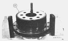

9. Remove inner drum (11) from the springs.

10. Remove eight outer springs (12) and eight inner springs (13) from the retainer.


11. Remove eight sleeves (14) from retainer (15).
12. Remove retainer (15).
Assemble Steering Clutches
1. Put tool (B) over the stud of tool (A).
2. Put retainer (3) on tool (B). Make sure that the bosses for the springs are up.

NOTICE
Check all of the springs of the steering clutch for correct spring tension. See the SPECIFICATIONS for the correct spring tension.

3. Install inner springs (2) and outer springs (1) on retainer (3).
4. Install inner drum (4) on the springs. Make sure the holes in the drum are in alignment with the springs.
5. Install tooling (C) and nut (5) on the stud of tool (A). Put force on the inner drum until the springs are under compression completely.

6. Install sleeeves (6) in the springs.
7. Install twelve disc assemblies (7) and eleven discs (8) in the correct sequence. Start with a disc assembly and stop with a disc assembly.
NOTE: For better wear distribution, the discs and disc assemblies must be installed so discs and disc assemblies that were on top of the steering clutch unit are now on the bottom.

8. Put pressure plate (9) in position. Make sure the holes in the pressure plate are in alignment with the holes in the inner drum.

9. Put 5P3931 Anti-Seize Compound on the threads of the bolts that hold the steering clutch together before they are installed. Install locks (11) and bolts (10) that hold the steering clutch together. Tighten the bolts to a torque of 150 ± 20 lb.ft. (205 ± 25 N·m).

10. Release the pressure on the steering clutch.
11. Remove nut (5) and tooling (C) from tool (A).
12. Install two 5/8"-11 NC forged eyebolts in outer drum (12). Fasten a hoist and put the outer drum in position over the steering clutch.
END BY:
a) install steering clutches

Copyright 1993 - 2021 Caterpillar Inc.
All Rights Reserved.
Private Network For SIS Licensees.
Mon Jul 26 17:17:14 UTC+0800 2021
13. Put brake band (13) in position on the outer drum.Previous Screen
Product: TRACK-TYPE TRACTOR
Model: D7G TRACK-TYPE TRACTOR 45W
Configuration: D7G LGP TRACTOR / DIRECT DRIVE / 45W00001-UP (MACHINE) POWERED BY 3306 ENGINE
Disassembly and Assembly
D7G TRACTOR POWER TRAIN
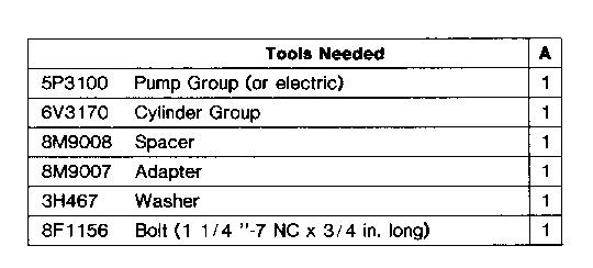
Final Drive Pinions And Flanges
SMCS - 4057-16; 4057-11; 4057-12; 4057-15; 4091
Remove Final Drive Pinions And Flanges
START BY:
a) remove steering clutches
1. Loosen nut (2) if the final drive pinion and flange (1) are to be disassembled.

2. Put the holes in the flange in alignment with bolts (3). Remove the bolts. The flange must be turned to remove some of the bolts.
3. Put the holes in the flange in alignment with the forcing screw holes in the bearing cage. Install two 5/8"-11 NC forcing screws. Tighten the screws evenly until the bearing cage is free of the bevel gear case.
4. Fasten a hoist to the final drive pinion and flange as a unit and remove it. Weight of the unit is 80 lb. (36 kg).

Install Final Drive Pinions And Flanges
1. Remove the old gasket material from the surface of the bevel gear case and bearing cage. Put 7M7260 Liquid Gasket on the surfaces.
2. Fasten a hoist to the final drive pinion and flange (1). Put the unit in position in the bevel gear case. Make sure the teeth of the final drive pinion and idler pinion gear are engaged. Make sure the pinion bearing race engages in its bearing.
3. Put the holes in the bearing cage and bevel gear case in alignment. Make sure the dowel in the bearing cage is up and the oil passage is down. Install the bolts that hold the bearing cage to the bevel gear case. Tighten the bolts by hand to a torque of 100 ± 10 lb.ft. (135 ± 14 N·m).
4. Tighten the large nut to a torque of 700 ± 100 lb.ft. (950 ± 135 N·m) and bend the lock against the side of the nut.
END BY:
a) install steering clutches
Disassemble Final Drive Pinions And Flanges

START BY:
a) remove final drive pinions and flanges
1. Remove the large nut from the pinion. Remove the bolt and lock from the flange.
Make sure the large nut is installed on the pinion shaft after the bolt and lock are removed. The flange is installed with a force of 35 to 40 ton (310 to 355 kN). The nut will keep the flange on the pinion shaft to prevent personal injury.
2. Install the large nut back on the pinion shaft until there is a distance of .125 in. (3.2 mm) between the nut and flange.
3. Install tooling (A) on the flange. Loosen flange (1) from the tapered splines. Remove tooling (A). Remove the large nut and flange (1) from the pinion shaft.


4. Remove gasket (2) from flange (1).
NOTE: Put identification on the Duo-Cone seals for correct installation.
Typical Example
5. Remove Duo-Cone seal (3) from flange (1).
6. Remove bearing cage (4) from the pinion shaft. Remove the Duo-Cone seals from the bearing cage.


7. Install a 10-32 screw in dowel (5) that holds the race and roller assembly in the bearing cage. Remove dowel (5) from bearing cage (4) with the screw.
8. Remove race and roller assembly (6) from bearing cage (4) with tooling (B).

9. Remove bearing races (7) and (8) from pinion shaft (9) with tooling (C).

Assemble Final Drive Pinions And Flanges
1. Heat bearing races (2) and (3) to a maximum temperature of 275°F (135°C). Install the two bearing races on pinion (1) as shown until they make contact with the shoulders on the pinion.

2. Lower the temperature of race and roller assembly (4). Make sure that the hole in the race is in alignment with the dowel hole in cage (5) and install the race and roller assembly in the bearing cage.

NOTE: The rubber seals and the surface that makes contact with the seals must be clean and dry. After installation of the seals, put clean oil on the contact surface of the metal seals.


 3. Install dowel (6) in bearing cage (5) to hold the race and roller assembly in position.
4. Put bearing cage (5) in position on pinion (1).
5. Install the Duo-Cone seal in bearing cage (5) with tooling (A).
6. Install the Duo-Cone seal in flange (7) with tooling (A).
7. Make sure the splines of the pinion and flange are clean and dry. Put flange (7) on pinion (1). Install tooling (B). Push the flange into position with a force of 35 to 40 ton (310 to 355 kN).
3. Install dowel (6) in bearing cage (5) to hold the race and roller assembly in position.
4. Put bearing cage (5) in position on pinion (1).
5. Install the Duo-Cone seal in bearing cage (5) with tooling (A).
6. Install the Duo-Cone seal in flange (7) with tooling (A).
7. Make sure the splines of the pinion and flange are clean and dry. Put flange (7) on pinion (1). Install tooling (B). Push the flange into position with a force of 35 to 40 ton (310 to 355 kN).
8. Remove tooling (B). Check the distance from the shoulder on the pinion shaft to the face of flange (7). This distance must be .12 ± .03 in. (3.0 ± 0.8 mm).
9. Install gasket (9) in the flange around the pinion shaft.
10. Put lock (8) in place on the flange and install bolt (11).

NOTE: If necessary, tighten nut (10) after the unit is installed in the machine.
11. Install nut (10) and tighten it to a torque of 700 ± 100 lb.ft. (950 ± 135 N·m). Bend the lock up.


END BY:
a) install final drive pinions and flanges
Copyright 1993 - 2021 Caterpillar Inc. All Rights Reserved. Private Network For
Previous Screen
Product: TRACK-TYPE TRACTOR
Model: D7G TRACK-TYPE TRACTOR 45W
Configuration: D7G LGP TRACTOR / DIRECT DRIVE / 45W00001-UP (MACHINE) POWERED BY 3306 ENGINE
Disassembly and Assembly
D7G TRACTOR POWER TRAIN
Steering Clutch Hubs

SMCS - 4101-11; 4101-12
Remove Steering Clutch Hubs
START BY:
a) remove steering clutches
1. Install two 3/8"-16 NC forcing screws (2) in piston (1). Pull the piston out of the steering clutch hub. Remove the seal ring from piston (1).

2. Install a 5/8"-11 NC bolt (3) 4 in. long and a nut through one of the holes in the steering clutch hub. Put a block of wood in the bottom of the steering clutch case. Turn the steering clutch hub until the bolt makes contact with the wood block.
3. Bend the lock down from nut (4). Remove nut (4), the lock and washer from the bevel gear shaft.
4. Remove pilot (5) from the bevel gear shaft. Remove the seal ring and O-ring seal from pilot (5).

NOTE: If necessary, the pilot can be removed with tooling (B).
Install nut (4) back on the end of the bevel gear shaft until there is a clearance of .375 in. (9.53 mm) between the nut and steering clutch hub. The nut will keep the hub on the shaft after it is removed from the tapered splines.
Typical Example
5. Install tooling (A) in the steering clutch hub. Use tooling (A) to loosen steering clutch hub (6) from the bevel gear shaft. Remove tooling (B) and nut (4).

6. Fasten a hoist to the steering clutch hub. Remove steering clutch hub (6) from the bevel gear shaft. The weight is 45 lb. (20 kg).
7. Remove seal rings (7) from steering clutch hub (6).

Install Steering Clutch Hubs
1. Install seal rings (2) on steering clutch hub (1). Put clean oil on the seals. NOTE: Make sure the splines on the bevel gear shaft and the splines in the steering clutch hub are clean and dry.
2. Put steering clutch hub (1) and washer in position on the bevel gear shaft. Push the steering clutch hub on the bevel gear shaft as far as possible by hand.
3. Install tooling (A). Push the steering clutch hub into position with a force of 35 to 40 tons (311 to 356 kN). Remove tooling (A) and the washer.


4. Check the distance between the face of the steering clutch hub and the shoulder on the bevel gear shaft [Dimension (X)]. Dimension (X) must be .12 ± .03 in. (3.0 ± 0.8 mm).
5. Install seal ring (5) and O-ring seal (3) on pilot (7). Put clean oil on the seals. Install pilot (7) in the steering clutch hub.
6. Install seal ring (8) on piston (4). Put clean oil on the seal ring. Install piston (4) in the steering clutch hub.
7. Install washer (9).
8. Install the lock and nut (6). Tighten the nut to a torque of 700 ± 100 lb.ft. (950 ± 135 N·m). Bend the lock.
END BY:
a) install steering clutches
Copyright 1993 - 2021 Caterpillar Inc.
All Rights Reserved.
Private Network For SIS Licensees.
Mon Jul 26 17:19:06 UTC+0800 2021
Previous Screen
Product: TRACK-TYPE TRACTOR
Model: D7G TRACK-TYPE TRACTOR 45W
Configuration: D7G LGP TRACTOR / DIRECT DRIVE / 45W00001-UP (MACHINE) POWERED BY 3306 ENGINE
Disassembly and Assembly
D7G TRACTOR POWER TRAIN
Bevel Gear And Shaft (Power Shift And Direct Drive)

SMCS - 3256-11; 3256-12
Remove Bevel Gear And Shaft
START BY:
a) remove steering clutch hydraulic control valve
b) remove steering clutch hubs
1. Remove cover (1) from the bevel gear case.
2. Remove the oil lines from each bearing cage.
3. Fasten a hoist to the bevel gear shaft for use as a support.

4. Remove bolts (2) from each bearing cage (3). Install two 1/2"-13 NC forcing screws in the bearing cage. Tighten the forcing screws evenly until the bearing cage is free of the bevel gear case.
5. Remove nuts (4), locks and the bolts that hold the bevel gear to the bevel gear shaft.


6. Move bevel gear shaft (5) into the steering clutch compartment on the right side. Fasten a hoist to the bevel gear shaft and remove it. Weight of the bevel gear shaft is 46 lb. (21 kg).


7. Fasten a hoist to the bevel gear and remove it from the bevel gear case. Weight of the bevel gear is 54 lb. (25 kg).

8. Remove the bearing cups from the two cages with tooling (A).
9. Remove the two bearings cones from the bevel gear shaft with tooling (B).
Install Bevel Gear And Shaft

1. Heat bearing cones (1) and (2) to a maximum temperature of 275°F (135°C). Install the bearing cones on the bevel gear shaft as shown.
2. Lower the temperature of the two bearing cups and install them in the bearing cages.
3. Fasten a hoist to bevel gear shaft (3). Install the bevel gear shaft without the bevel gear if the transmission is in the machine or with the bevel gear if the transmission is out of the machine.


NOTE: The following procedure is with the power shift transmission in position in the machine.
4. Make an adjustment to the bearings on the bevel gear shaft for the power shift machine as follows:
a) Install bearing cage (7) with a full package of shims (5). Tighten bolts (7), without the lockwashers, evenly. The thickness of a full shim pack is .119 to .125 in. (3.02 to 3.18 mm).
b) Install bearing cage (9) without shims (4).
c) Tighten bolts (8), without the lockwashers, evenly as bevel gear shaft (10) is turned slowly until the torque needed to turn the bevel gear shaft (3) is 70 to 85 lb.in. (7.9 to 9.6 N·m).

d) Measure the distance between the flange of bearing cage (9) and the face of the bevel gear case with a feeler gauge. Measure the distance at each of the bolts around bearing cage (9). Make sure the distance is the same at each of the bolts.
e) Remove bearing cage (9). Install an amount of shims (4) the same thickness as the distance measured in Step d. Install bearing cage (9) and bolts (8) with the lockwashers. Tighten bolts (8) evenly to a torque of 100 ± 10 lb.ft. (135 ± 14 N·m).
f) Install bolts (7) with the lockwashers. Tighten the bolts evenly to a torque of 100 ± 10 lb.ft. (135 ± 14 N·m).
g) Check the torque that is needed to turn bevel gear shaft (3) again. The torque must be 70 to 85 lb.in. (8 to 9.7 N·m).
5. Make an adjustment to the bevel gear for the correct gear clearance (backlash) for the power shift machine as follows:
a) Install the transmission. See INSTALL TRANSMISSION or remove the two bearing cages and the bevel gear shaft from the bevel gear case. Put identification on the shims to keep them together for correct location when the bevel gear and shaft is installed.
b) Fasten a hoist to the bevel gear and put it in the correct position in the bevel gear case. Install the bevel gear shaft, the two bearing cages and the shims. Install the bolts, nuts and locks that hold the bevel gear to the bevel gear shaft.
c) Install tool (A) so the indicator tip is on one tooth of the bevel pinion.
d) Put a block of wood between bevel gear (10) and the case so the bevel gear will not turn.
e) Push the bevel pinion toward the front of the machine as far as possible. Move the bevel pinion clockwise and then counterclockwise. The free movement (backlash) will be the difference in the values read on the dial indicator.
f) Measure the gear clearance (backlash) at four points around the bevel gear to find the point of the smallest gear clearance (backlash).
NOTE: Make sure the bevel pinion is held as far as possible toward the front of the machine when the gear clearance (backlash) is measured.
g) The correct backlash is .015 + .004 or - .003 In. (0.38 + 0.10 or - 0.08 mm).
h) If the measurement of the smallest gear clearance (backlash) is too large, remove some of shims (5) from behind bearing cage (6). Install the shims (that were removed) behind bearing cage (9).
i) If the measurement of the smallest gear clearance (backlash) is too small, remove some of shims (4) from behind bearing cage (9). Install the shims (that were removed) behind bearing cage (6).
NOTE: The adjustment of the bearings for bevel gear shaft (3) will not change by the movement of shims from one bearing cage to the other bearing cage as long as the total thickness of shims is the same.
6. Make an adjustment of the bearings for the bevel gear shaft for the direct drive as follows:
a) Install bevel gear shaft (3) in the machine without bevel gear (10), if the transmission is installed in the machine. Install bevel gear shaft (3) in the machine with the bevel gear (10) if the transmission is not installed.

b) Install bearing cage (6) with a full package of shims (5). Tighten bolts (7) without the lockwashers evenly. The thickness of a full shim pack is .119 to .125 in. (3.02 to 3.18 mm).
c) Install bearing cage (9) without shims (4).
d) While bevel gear shaft (3) is turned slowly, tighten bolts (8) without the lockwashers evenly until the torque needed to turn the bevel gear shaft is 70 to 85 lb.in. (8 to 9.7 N·m).
e) Measure the distance between the flange of bearing cage (9) and the face of the bevel gear case with a feeler gauge. Measure the distance at each of the bolts around bearing cage (9). Make sure the distance is the same at each of the bolts.
f) Remove bearing cage (9). Install an amount of shims (4) the same thickness as the distance measured in Step 3. Install bearing cage (9) and bolts (8) with the lockwashers. Tighten bolts (8) evenly to a torque of 100 ± 10 lb.ft. (135 ± 14 N·m).
g) Install bolts (7) with the lockwashers. Tighten the bolts evenly to 100 ± 10 lb.ft. (135 ± 14 N·m).
h) Check the torque that is needed to turn bevel gear shaft (3) again. The torque must be 70 to 85 lb.in. (7.9 to 9.6 N·m).
7. Make an adjustment of the free movement (backlash) for the direct drive as follows:
a) Install the transmission. See INSTALL TRANSMISSION or install the bevel gear. See Steps 5a and 5b.

b) Install a dial indicator so the indicator tip is on tooth of bevel pinion (11).
c) Put a block of wood between bevel gear (10) and the case so the bevel gear does not turn.
d) Move bevel pinion (11) clockwise and then counterclockwise. The free movement (backlash) will be the difference in the values read on the dial indicator.
Thank you very much for your reading. Please Click Here. Then Get COMPLETE MANUAL. NO WAITING

NOTE:
If there is no response to click on the link above, please download the PDF document first and then click on it.
e) Measure the free movement (backlash) at four points around the bevel gear to find the point of smallest free movement (backlash).
f) The correct amount of free movement (backlash) between the bevel gear and pinion is .010 + .004 or - .003 in. (0.25 + 0.10 or - 0.08 mm).
g) if the measurement of the smallest gear clearance (backlash) is too large, remove some of the shims (5) from behind bearing cage (6). Install the shims (that were removed) behind bearing cage (9).
h) if the measurement of the smallest gear clearance (backlash) is too small, remove some of shims (4) from behind cage (9). Install the shims (that were removed) behind bearing cage (6).
NOTE: The adjustment of the bearings for bevel gear shaft (3) will not change by the movement of shims from one bearing cage to the other as long as the total thickness of shims is the same.
Alignment Of Bevel Gear And Pinion

8. After bevel gear bearing preload and gear clearance (backlash) adjustments have been made, check the tooth contact setting between the bevel gear and bevel pinion shaft as follows:
a) Put a small amount of prussian blue, red lead or paint on the bevel gear teeth. Turn the bevel pinion shaft and check the marks made on the bevel gear teeth.
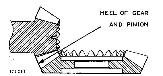
b) With no load, correct tooth setting will be as shown. The area of contact starts near toe of gear and goes 30% up the length of the tooth. With this setting, when load is put on the gear it will be over the correct area of teeth.
Short Toe Contact Setting
c) If the bevel pinion shaft is too far away from the bevel gear, short toe contact will be the result as shown. The teeth of the bevel pinion shaft will be in contact with toe ends of convex faces (part that makes a curve toward outside), and top edge of heel end of concave faces (part that makes a curve toward inside). To correct this, add shims (12) between bevel pinion shaft and bearing cage of transmission. Check gear clearance (backlash) and tooth contact again.
Short Heel Contact Setting
d) If the bevel pinion shaft is too near to the center of the bevel gear, short heel contact will be the result as shown. The teeth of the bevel pinion shaft will be in contact with the toe ends of concave faces (part that makes a curve toward the inside) and the heel ends of convex faces (part that makes a curve toward the outside). To correct this, move the pinion shaft away from the bevel gear by removal of shims (12) between the bearing cage of the transmission and bevel pinion shaft. After doing this, check the gear clearance (backlash) and tooth contact again.


NOTE: several adjustments must be made for the correct tooth contact setting. If the gear clearance (backlash) is changed, the tooth contact setting will change.
9. Remove all of the prussian blue, red lead or paint from the bevel gear and bevel pinion shaft.
END BY:
a) install steering clutch hubs
b) install steering clutch hydraulic control valve
Previous Screen
Product: TRACK-TYPE TRACTOR
Model: D7G TRACK-TYPE TRACTOR 45W
Configuration: D7G LGP TRACTOR / DIRECT DRIVE / 45W00001-UP (MACHINE) POWERED BY 3306 ENGINE
Disassembly and Assembly
D7G TRACTOR POWER TRAIN
Rear Bottom Guard
SMCS - 7153-11; 7153-12
Remove Rear Bottom Guard
Fasten the rear bottom guard to the floor jack before the bolts that hold it in place are removed. The rear bottom guard can fall and cause personal injury.
1. Put a floor jack in position under rear bottom guard (2) as shown.
2. Remove bolts (1) that hold the rear bottom guard to the frame of the machine. Lower the rear bottom guard. The weight of the rear bottom guard is 350 lb. (159 kg).
