
SERVICE MANUAL
Foreword
The Operator's Manual
You and others can be killed or seriously injured if you operate or maintain the machine without first studying the Operator's Manual. You must understand and follow the instructions in the Operator's Manual. If you do not understand anything, ask your employer or JCB dealer to explain it.
Do not operate the machine without an Operator's Manual, or if there is anything on the machine you do not understand.
Treat the Operator's Manual as part of the machine. Keep it clean and in good condition. Replace the Operator's Manual immediately if it is lost, damaged or becomes unreadable.
00 - General
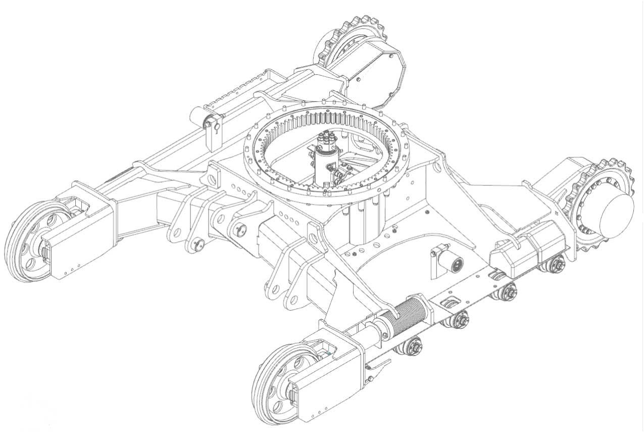
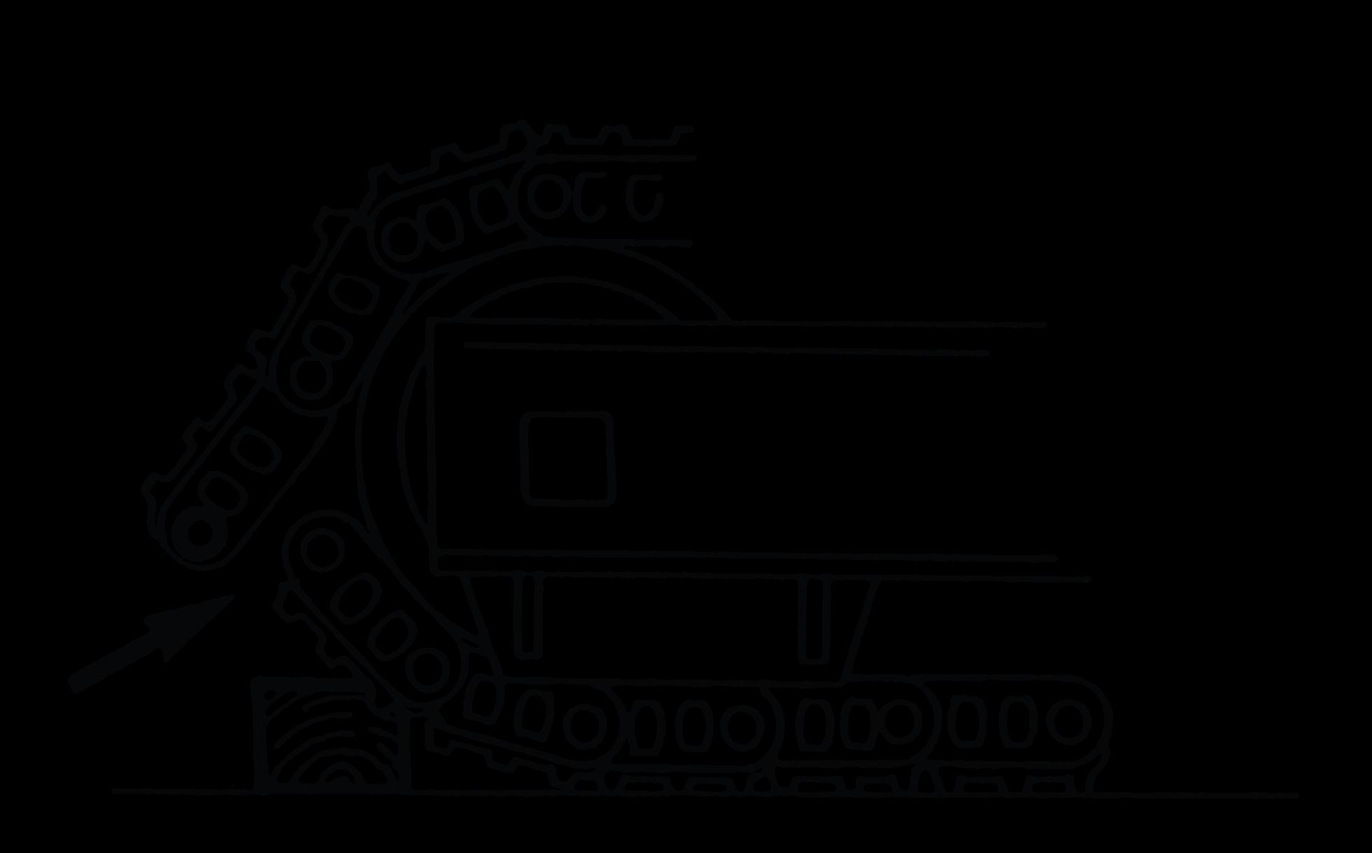
The excavator track and running gear is located on and within the machine undercarriage track boxes.
Health and Safety
Raised Machine
Never position yourself or any part of your body under a raised machine which is not correctly supported. If the machine moves unexpectedly you could become trapped and suffer serious injury or be killed.
CAUTION! The following operations must only be undertaken by persons familiar with track changing operations and who are qualified to perform the operations. All persons must keep clear of the machine driven sprocket.
CAUTION! Ensure that all persons are clear of the track and especially of the driven sprocket during the following operations.
Notice: When converting a machine from steel tracks to rubber tracks, the track guides must be removed. When converting from rubber tracks to steel tracks the track guides must be installed. Damage to the tracks may result if this is not carried out.
WARNING! Recoil unit servicing must only be carried out by JCB dealers. You could be killed or injured if you tamper with it.
CAUTION! The recoil unit spring can cause serious injury if suddenly released. Take great care when removing and replacing the spring retaining nut. Scrap recoil units must be dismantled before transfer from the workshop. Do not use flame cutting equipment unless precautions are taken to release the spring pressure slowly.
Technical Data
Table
136. Undercarriage
Parameter
Construction
Specification
Fully welded H-frame type central belly guarding and sloping side members
Upper and lower rollers Heat treated, sealed and lubricated
Track type Sealed and greased steel or continuous rubber
Track adjustment Grease cylinder type Track idler Sealed and lubricated, with spring cushioned recoil
Track shoes
400 mm steel triple grouser
550 mm steel triple grouser
400 mm Geo-Grip track
400 mm rubber tracks
Rollers and shoes (each side)
Upper roller - 1
Lower rollers - 4
Track shoes - 39
Table 137. Standard Boom - Weights and Ground Bearing Pressures
Machine equipped with boom 1.9 m, dipper arm and 600 mm excavating bucket. With the machine operator and full fuel tank.
Table 138. Track Tension
Adjust
WARNING Recoil unit servicing must only be carried out by JCB dealers. You could be killed or injured if you tamper with it.
Notice: Always make sure that the track tension measurement is not less than specified or severe strain to the track will result.
Check The Tension
1.Park the machine on solid, level ground.
2.Operate the tracks backwards and forwards several times.
3.Stop the machine after operating the tracks forwards.
4.Set the machine in the posture shown with the track to be checked raised from the ground and supported. Add a support under the machine. It is the responsibility of the operator to support the machine correctly.
2.Add grease through the nipple in the adjusting screw until track tension is correct.
3.Rotate the track. Track tension will increase during rotation.
4.Check the track tension at its tightest point to avoid over tensioning.
5.Install the cover plate.
Loosen the Track
1.Remove the cover plate (if installed).
2.Loosen adjusting screw until track tension is correct.
3.Rotate the track. Track tension will increase during rotation.
4.Check the track tension at its tightest point to avoid over tensioning.
5.Install the cover plate.
Figure 329.
A Support
5.Check that the tension measurement is correct. Refer to: PIL 27-36-00.
A Cover plate (if installed)
B Nipple
C Adjusting screw
A Tension measurement
5.1.If the measurement is incorrect then you must adjust the track tension.
Tighten the Track
1.Remove the cover plate.
Remove and Install
CAUTION The recoil unit spring can cause serious injury if suddenly released. Take great care when removing and replacing the spring retaining nut. Scrap recoil units must be dismantled before transfer from the workshop. Do not use flame cutting equipment unless precautions are taken to release the spring pressure slowly.
Changing Tracks from Steel to Rubber Tracks
1.Make the machine safe.
Refer to: PIL 01-03.
2.Remove the steel tracks.
Refer to: PIL 27-36-03.
3.Remove the recoil units.
Refer to: PIL 27-36-27.
4.Attach the bottom rollers into the correct mounting holes for the rubber tracks.
Refer to: PIL 27-36-24.
5.Install the recoil units.
Refer to: PIL 27-36-27.
5.1.The idler wheels are different for steel and rubber tracks. Make sure that the correct idler wheels are installed.
6.Install the rubber tracks.
Refer to: PIL 27-36-06.
7.Adjust the track tension.
Refer to: PIL 27-36-00.
Changing Tracks from Rubber to Steel Tracks
1.Make the machine safe.
Refer to: PIL 01-03.
2.Remove the rubber tracks.
Refer to: PIL 27-36-06.
3.Remove the recoil units.
Refer to: PIL 27-36-27.
4.Attach the bottom rollers into the correct mounting holes for the steel tracks.
Refer to: PIL 27-36-24.
5.Install the recoil units.
Refer to: PIL 27-36-27.
5.1.The idler wheels are different for steel and rubber tracks. Make sure that the correct idler wheels are installed.
6.Install the steel tracks.
Refer to: PIL 27-36-03.
7.Adjust the track tension. Refer to: PIL 27-36-00.
03 - Steel Track
Remove and Install
Remove
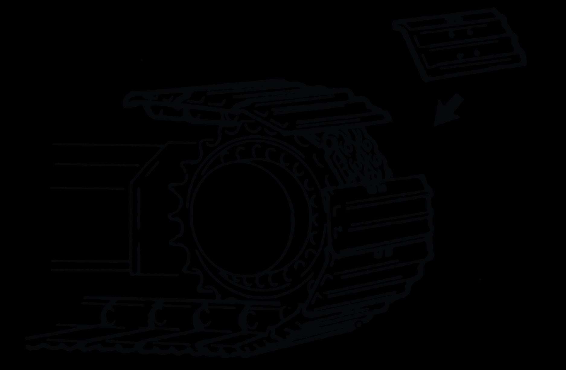
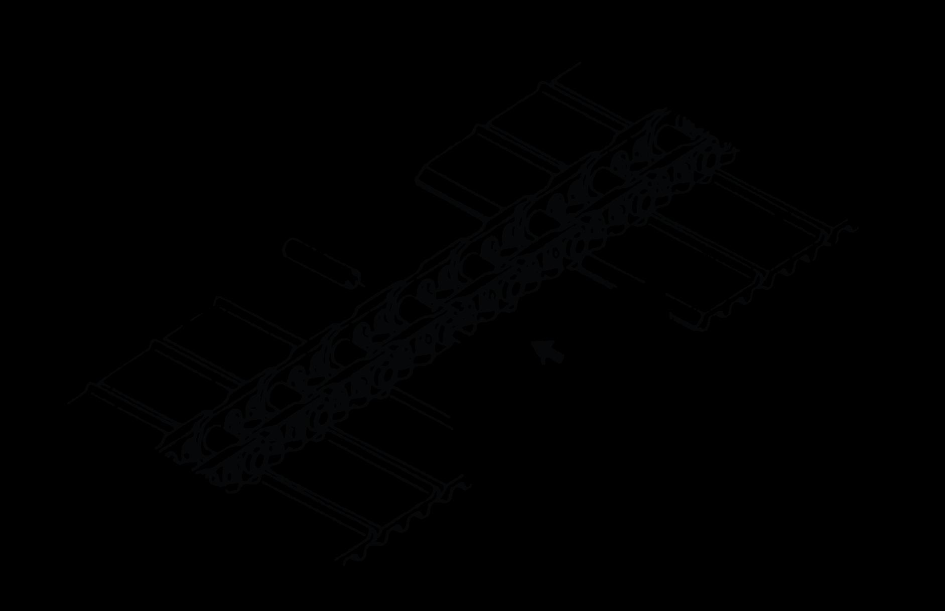
1.Move the track until the master pin takes the position over the idler wheel. Refer to Figure 330.
2.Put a wooden block below the track shoe. Refer to Figure 330.


A Master pin
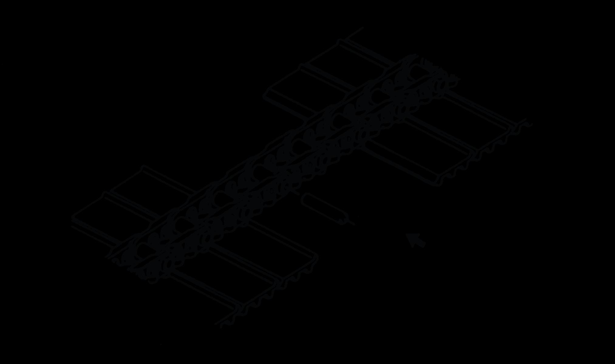
4.2.Put a suitable hydraulic press and align the ram with the master pin.
4.3.Insert the spacer bar between the master pin and the hydraulic ram.
4.4.Slowly operate the hydraulic ram and press out the master pin. Refer to Figure 333.
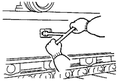
3.Loosen the check valve to bleed out the grease and release the track tension. Refer to Figure 331.
4.Remove the master pin.
4.1.Remove the bolts and remove the track shoes adjacent to the master pin. Refer to Figure 332.
4.5.Remove the seal rings from each side of the chain link.
5.Drive the machine forward to remove the track. Refer to Figure 334.
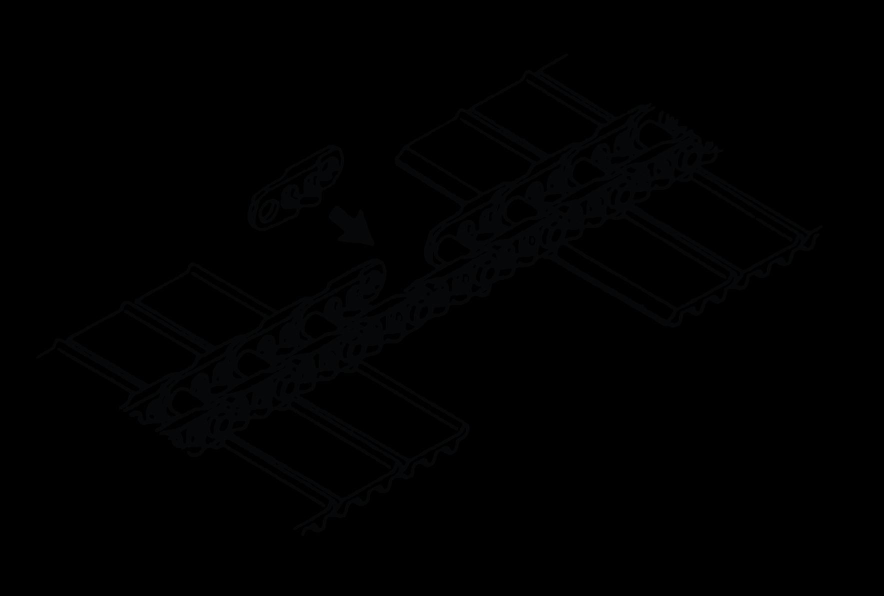
6.Raise the side of the machine using the boom and dipper operations. Refer to Figure 335.
7.Put wooden blocks below the frame to support the machine. Refer to Figure 335.
3.Put the track on the ground below the lower rollers with one end under the idler wheel.
8.Remove the track. Install
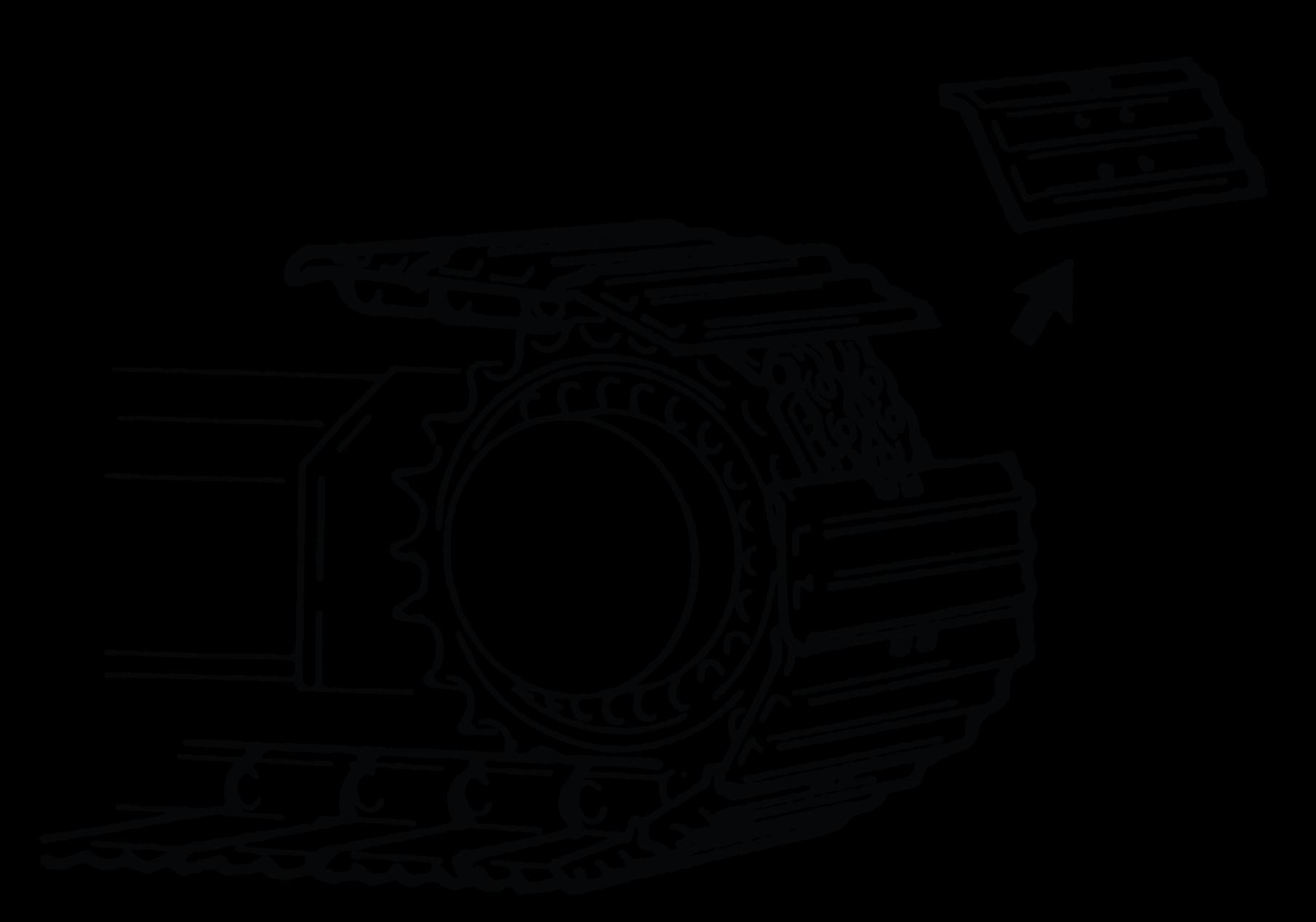
1.Raise the side of the machine using the boom and dipper operations. Refer to Figure 336.


2.Put wooden blocks below the frame to support the machine. Refer to Figure 336.
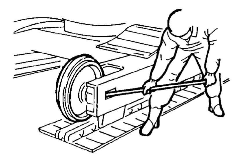
4.Attach the lifting equipment to lift the track end and engage the track in the drive sprocket.
5.Slowly operate the drive sprocket in the forward direction.
6.While still supporting the end of the track with the lifting equipment, continue to operate the sprocket in the forward direction until the track end reaches over the idler wheel.
7.Lower the machine, make sure that the track engages into the bottom rollers.
11.Insert the master pin into the hole. Figure
12.Slowly operate the hydraulic ram and press the master pin into position.
13.Attach the track shoes and tighten the bolts. Refer to: PIL 27-36-04.
14.Adjust the track tension. Refer to: PIL 27-36-00.
04 - Shoe Plate
Remove and Install Remove
1.Make the machine safe. Refer to: PIL 01-03.
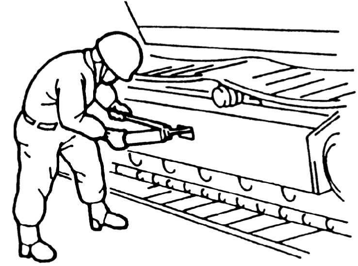
2.Put the damaged shoe plate over the drive sprocket. Refer to Figure 345.
3.Remove the bolts and nuts that attach the shoe plate to the track link. Refer to Figure 345.
Install
1.Put the new shoe plate on the track link. Refer to Figure 347.
A Track shoe
B Bolts
C Nuts
4.Remove the damaged shoe plate. Refer to Figure 346.
D Track link
E New track shoe
2.Use the bolts and nuts to install the shoe plate to the track link.
3.Tighten the bolts in diagonal sequence. Refer to Figure 348.

A Bolt number 1
B Bolt number 2
C Bolt number 3
D Bolt number 4
A Track shoe
D Track link
05 - Track Link
Remove and Install Remove
1.Make the machine safe. Refer to: PIL 01-03.
2.Put the track link over the idler wheel. Refer to Figure 349.
3.Put a wooden block below the track shoe to support the track link. Refer to Figure 349.
6.Use a portable hydraulic press to remove the track pins that attach the link. Refer to Figure 352.
4.Loosen the check valve to bleed out the grease and release the track tension. Refer to Figure 350.
7.Remove the damaged link. Refer to Figure 353.


5.Remove the shoe plate that is attached to the damaged track link and a further shoe plate on either side.Refer to Figure 351. Refer to: PIL 27-36-04.
8.Replace the damaged link with a new one.
Install
1.Align the new link with the existing side links. Refer to Figure 354.
4.Adjust the track tension. Refer to: PIL 27-36-00.
5.Remove the wooden block from below the track.
2.Use a portable hydraulic press to install the new track pins. Refer to Figure 355.
3.Install the shoe plates.Refer to Figure 356. Refer to: PIL 27-36-04.
06 - Rubber Track
Remove and Install
WARNING A raised and badly supported machine can fall on you. Position the machine on a firm, level surface before raising one end. Ensure the other end is securely chocked. Do not rely solely on the machine hydraulics or jacks to support the machine when working under it. Disconnect the battery, to prevent the machine being started while you are beneath it.
CAUTION The following operations must only be undertaken by persons familiar with track changing operations and who are qualified to perform the operations. All persons must keep clear of the machine driven sprocket.
Remove
1.Make the machine safe. Refer to: PIL 01-03.
2.Set the machine in the position shown with the track to be removed, raised from the ground and supported.
A Bolt
B Access plate
C Adjusting screw
D Grease adaptor
Install
1.Install the track on to the machine.
2.Make sure that the marked joint of the track is in the top centre position.
3.Tighten the grease adaptor.
4.Adjust the tension of the tracks. Refer to: PIL 27-36-00.
5.Operate the controls slowly to lower the track to the ground.
3.Slowly loosen the grease adaptor to release all the pressure from the track.
4.Remove the track from the machine.
12 - Gearbox Sprocket
Remove and Install
6.Raise the side of the machine using the boom and dipper operations. Refer to Figure 361.
7.Put wooden blocks below the frame to support the machine. Refer to Figure 361.
Figure 361.
Remove
1.Make the machine safe. Refer to: PIL 01-03.
2.Loosen the check valve to bleed out the grease from the tensioner. Refer to Figure 359.
8.Support the drive sprocket and remove the bolts that attach the drive sprocket to the gearbox. Refer to Figure 362.
9.Move the drive sprocket away from the gearbox unit. Refer to Figure 362.
Figure 362.
3.Remove the master pin to disconnect the track link.
Refer to: PIL 27-36-05.
4.Drive the machine forward to remove the track. Refer to Figure 360.

360.
5.Remove the track from the sprocket.
A Drive sprocket
B Bolts
C Washers
9.1.Remove the drive sprocket.
Install
1.Support the drive sprocket and put the drive sprocket on the gearbox.
2.Apply the JCB Threadlocker and Sealer on the bolts.
Consumable: JCB Threadlocker and Sealer (High Strength)
3.Install the bolts and washers to attach the drive sprocket to the gearbox. Refer to Figure 363.
A Drive sprocket
B Bolts
C Washers
4.Tighten the bolts to the correct specified torque value in a diagonal sequence.
Torque: 167 N·m
5.Raise the side of the machine using the boom and dipper operations.
6.Remove the wooden blocks from below the machine frame.
7.Connect the track link. Refer to: PIL 27-36-05.
8.Adjust the track tension. Refer to Figure 364. Refer to: PIL 27-36-00.
18 - Idler Wheel
Remove and Install
Refer to: PIL 27-36-27.
21 - Top Roller
Remove and Install
Remove
1.Make the machine safe. Refer to: PIL 01-03.
2.Loosen the check valve to bleed out the grease from the tensioner. Refer to Figure 365.
Refer to: PIL 27-36-00.
3.Put the jack on the side frame below the track. Refer to Figure 366.
4.Liftthetrackhighenoughtoremovethetoproller. Refer to Figure 366.
5.Putwoodenblocksbetweenthetracklinkandthe side frame. Refer to Figure 366.
A Top roller
B Track
C Side frame
D Jack
6.Loosen the mounting bolt, washers and nut that attach to the top roller. Refer to Figure 367.
6.1.Do not remove the mounting bolt, washers and nut completely.
A Top roller
B Bolt
C Washers
D Nut
E Spacers
7.Tap the top roller with a copper mallet to separate from the side frame.
8.Remove the mounting bolt, washers and nut.
9.Remove the top roller with any spacers. Refer to Figure 368.
A Top roller
Install
1.Fill the roller with the specified oil. Refer to: PIL 75-00-00.
2.Use an appropriate pipe thread sealant to install the plug. Refer to Figure 369.
A Top roller B Track
C Side frame
D Jack
5.Apply the JCB Threadlocker and Sealer on the mounting bolt.
Consumable: JCB Threadlocker and Sealer (Medium Strength)
6.Install the mounting bolt, washers and nut to attach the top roller to the side frame.
7.Use the spacers to install the top roller and to makesurethatthetoprollerisalignedtothetrack at center.
8.Tighten the mounting bolt to the correct specified torque value.
9.Remove the wooden blocks and jack from below the track.
10.Adjust the track tension. Refer to: PIL 27-36-00.
A Plug
3.Lift the track high enough to install the top roller. Refer to Figure 370.
4.Install the top roller Refer to Figure 370.
24 - Bottom Roller
Remove and Install
Remove
1.Make the machine safe. Refer to: PIL 01-03.
2.Loosen the check valve to bleed out the grease from the tensioner. Refer to Figure 372. Refer to: PIL 27-36-00.
3.Raise the side of the machine using the boom and dipper operations. Refer to Figure 373.
3.1.Raise the side of the undercarriage high enough to remove the bottom roller.
4.Put wooden blocks below the frame to support the machine. Refer to Figure 373.
A Bolts and washers
6.Tap the bottom roller with a copper mallet to separate it from the side frame.
7.Remove the bottom roller.
Install
1.Fill the roller with the specified oil. Refer to: PIL 75-00-00.
2.Use an appropriate pipe thread sealant to install the plug.
3.The rollers must be mounted in the upper holes for the rubber tracks, and in the lower holes for the steel tracks. Refer to Figure 375.
5.Remove the mounting bolts and washers that attach to the bottom roller. Refer to Figure 374.
Thank you very much for your reading. Please Click Here. Then Get COMPLETE MANUAL.NOWAITING

NOTE:
If there is no response to click on the link above, please download the PDF document first and then clickonit.
A Bolts and washers
B Lower hole (steel track)
C Upper hole (rubber track)
4.Install the mounting bolts and washers.
4.1.The two outer mounting bolts at the idler wheel end of the track are longer by the specified length than the others.
Length: 10 mm
5.Tighten the bolts to the correct torque value.
6.Adjust the track tension. Refer to: PIL 27-36-00.
27 - Tensioner/Recoil unit
Health and Safety
WARNING Recoil unit servicing must only be carried out by JCB dealers. You could be killed or injured if you tamper with it.
CAUTION The recoil unit spring can cause serious injury if suddenly released. Take great care when removing and replacing the spring retaining nut. Scrap recoil units must be dismantled before transfer from the workshop. Do not use flame cutting equipment unless precautions are taken to release the spring pressure slowly.
Remove and Install
CAUTION The recoil unit spring can cause serious injury if suddenly released. Take great care when removing and replacing the spring retaining nut. Scrap recoil units must be dismantled before transfer from the workshop. Do not use flame cutting equipment unless precautions are taken to release the spring pressure slowly.
Remove
1.Make the machine safe.
Refer to: PIL 01-03.
2.Loosen the check valve to bleed out the grease from the tensioner.
Refer to: PIL 27-36-00.
3.Remove the master pin to disconnect the track link. Refer to Figure 376.
Refer to: PIL 27-36-05.
5.Removetheidlerwheel,tensionerandrecoilunit. Refer to Figure 378.
Figure 378.
4.Use a steel bar to move the idler wheel and recoil assembly to the end of the undercarriage. Refer to Figure 377.
A Idler wheel
B Tensioner
C Recoil unit
Install
1.Before the idler wheel installation, check the hydraulic oil level.
1.1.If required, fill with the specified hydraulic oil.
2.Make sure that the tensioner is fully retracted.
3.Use suitable lifting equipment to assemble the recoil unit, tensioner and idler wheel into the undercarriage. Refer to Figure 379.
Figure 379.
A Idler wheel
B Tensioner
C Recoil unit
4.Use a steel bar to put the idler wheel in the undercarriage. Refer to Figure 380.